Table of Contents
Advertisement
No. SX-DSV03335
REFERENCE SPECIFICATIONS
MOD E L
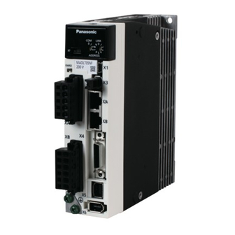
Product Name AC Servo Driver
MINAS A6B for linear motor/DD motor
Product No.
(standard type/multi-function type)
Issued on Mar. 20, 2019
Reviced on Apr. 8, 2020
Industrial Device Solution Business Unit, Industrial Device Business Division,
Industrial Solutions Company, Panasonic Corporation
7-1-1 Morofuku, Daito-City, Osaka 574-0044, Japan
Phone:+81-(0)72-871-1212
Fax :+81-(0)72-870-3151
Advertisement
Table of Contents

Related Manuals for Panasonic MINAS A6B Series


Summary of Contents for Panasonic MINAS A6B Series
- Page 1 MINAS A6B for linear motor/DD motor Product No. (standard type/multi-function type) Issued on Mar. 20, 2019 Reviced on Apr. 8, 2020 Industrial Device Solution Business Unit, Industrial Device Business Division, Industrial Solutions Company, Panasonic Corporation 7-1-1 Morofuku, Daito-City, Osaka 574-0044, Japan Phone:+81-(0)72-871-1212 Fax :+81-(0)72-870-3151...
- Page 2 Apr. 16, 2019 Correct the tabe in “3. Product Line-up” P5,6 Apr. 8 , 2020 Added 400 V input models Update other contents according to the latest Japanese version Clerical error correction R2.0 Industrial Device Solution Business Unit, Panasonic Corporation...
- Page 3 12-1 Warranty period ............................89 12-2 Warranty scope ............................. 89 12-3 Guarantee service ............................89 13. Others .................................. 90 14. Specification for each model ..........................92 Appended table : efault value of the parameters R2.0 Industrial Device Solution Business Unit, Panasonic Corporation...
- Page 4 • All rights reserved. No part of this publication may be reproduced or transmitted in any form without prior permission. • Motor Business Unit, Panasonic Corporation reserves the right to make modifications and improvements to its products and/or documentation, including specifications and software, without prior notice.
- Page 5 Output classification 1 : Single phase 100 V This means 3 : 3 phase 200 V adapted motor size 4 : 3 phase 400 V 5 : Single or 3 phase 200 V R2.0 Industrial Device Solution Business Unit, Panasonic Corporation...
- Page 6 The type and the maximum rated current of the applicable motor, please refer to the individual (Note 3) specifications. *There is no correspondence of Size G and Size H and 400 V input models for standard type. R2.0 Industrial Device Solution Business Unit, Panasonic Corporation...
- Page 7 (Note 2) This shows that this product has passed the EtherCAT conformance Test conducted at EtherCAT test center. (Note 3) The type and the maximum rated current of the applicable motor, please refer to the individual specifications. R2.0 Industrial Device Solution Business Unit, Panasonic Corporation...
- Page 8 For details of functions and available countries or areas, please check our website *4 It can not be used for standard type For details of each specification, refer to Technical Reference - Functional Specification R2.0 Industrial Device Solution Business Unit, Panasonic Corporation...
- Page 9 A phase A phase B phase B phase Please note that if the duty ratio of the scale input signal waveform is not 50%, it may not be able to be read normally R2.0 Industrial Device Solution Business Unit, Panasonic Corporation...
- Page 10 XA: Power input connector M ain power supply input XB: M otor output connector Control power supply input Regenerative resistor connection M otor output *Remove the safety bypass plug when wiring to X3. R2.0 Industrial Device Solution Business Unit, Panasonic Corporation...
- Page 11 3E106-2230KV (3M ) or equivalent M ain power supply input Control power supply input XB: M otor output connector Regenerative resistor connection M otor output *Remove the safety bypass plug when wiring to X3. R2.0 Industrial Device Solution Business Unit, Panasonic Corporation...
- Page 12 Control power supply input Regenerative resistor connection M otor output XA: Power input connector Earth connection screw XC: Regenerative resistor connector XB: M otor connector *Remove the safety bypass plug when wiring to X3. R2.0 Industrial Device Solution Business Unit, Panasonic Corporation...
- Page 13 X6: CS signal connector 3E106-2230KV (3M) or equivalent Main power supply input Control power supply input Regenerative resistor connection Motor output *Remove the safety bypass plug when wiring to X3. R2.0 Industrial Device Solution Business Unit, Panasonic Corporation...
- Page 14 5569-04A2-210(M OLEX) screw or equivalent XS: Internal DB switch Control power supply input M ain power supply input Regenerative resistor connection M otor output *Remove the safety bypass plug when wiring to X3. R2.0 Industrial Device Solution Business Unit, Panasonic Corporation...
- Page 15 External DB control connection L1C L2C DB1 DB2 Control power supply input Earth connection screw M ain power supply Regenerative resistor M otor output input connection *Remove the safety bypass plug when wiring to X3. R2.0 Industrial Device Solution Business Unit, Panasonic Corporation...
- Page 16 M ain power supply input XA: Power input connector Regenerative resistor connection XC: Regenerative resistor connector M otor output XB: M otor output connector *Remove the safety bypass plug when wiring to X3. R2.0 Industrial Device Solution Business Unit, Panasonic Corporation...
- Page 17 Input connector Regenerative resistor connection M otor output XA: Power input connector Earth connection screw XC: Regenerative resistor connector XB: M otor output connector *Remove the safety bypass plug when wiring to X3. R2.0 Industrial Device Solution Business Unit, Panasonic Corporation...
- Page 18 XD: Control power supply Input connector Control power supply input M ain power supply input Regenerative resistor connection (Normal RB-B short circuit) M otor output *Remove the safety bypass plug when wiring to X3. R2.0 Industrial Device Solution Business Unit, Panasonic Corporation...
- Page 19 B000 - B999 17000 - 17999 H000 - H999 18000 - 18999 J000 - J999 22000 - 22999 N000 - N999 23000 - 23999 P000 - P999 33000 - 33999 Z000 - Z999 R2.0 Industrial Device Solution Business Unit, Panasonic Corporation...
- Page 20 2-digit 7-segment LED RUN LED (green) Link/Activity IN LED (green) ERROR LED (red) Link/Activity OUT LED (green) 2-digit rotary switch for node Address setting Setting range:0 - FF Analog monitor connector(X7) X7-1pin R2.0 Industrial Device Solution Business Unit, Panasonic Corporation...
- Page 21 [Base-mounting installation (Standard: Mounting on the back)] 2-M4 Effective screw depth 5 Name Plate 2-M4 Effective screw depth 5 Unit: mm * Do not use threaded screw holes that do not have description of dimensions. R2.0 Industrial Device Solution Business Unit, Panasonic Corporation...
- Page 22 Mounting Bracket (optional part) Unit: mm * Do not use threaded screw holes that do not have description of dimensions. * Mounting brackets are optional parts. They are not included with the product. R2.0 Industrial Device Solution Business Unit, Panasonic Corporation...
- Page 23 [Base-mounting installation (Standard: Mounting on the back)] 2-M4 Effective screw depth 5 Name Plate 2-M4 Effective screw depth 5 Unit: mm * Do not use threaded screw holes that do not have description of dimensions. R2.0 Industrial Device Solution Business Unit, Panasonic Corporation...
- Page 24 Mounting Bracket (option part) Unit: mm * Do not use threaded screw holes that do not have description of dimensions. * Mounting brackets are optional parts. They are not included with the product. R2.0 Industrial Device Solution Business Unit, Panasonic Corporation...
- Page 25 [Base-mounting installation (Standard: Mounting on the back)] 2-M4 Effective screw depth 5 Name Plate 2-M4 Effective screw depth 5 Unit: mm * Do not use threaded screw holes that do not have description of dimensions. R2.0 Industrial Device Solution Business Unit, Panasonic Corporation...
- Page 26 Mounting Bracket (optional part) Unit: mm * Do not use threaded screw holes that do not have description of dimensions. * Mounting brackets are optional parts. They are not included with the product. R2.0 Industrial Device Solution Business Unit, Panasonic Corporation...
- Page 27 2-M4 Effective screw depth 5 Unit: mm Note 1) The dimensions of the 400 V system are 188 mm. * Do not use threaded screw holes that do not have description of dimensions. R2.0 Industrial Device Solution Business Unit, Panasonic Corporation...
- Page 28 Note 1) The dimensions of the 400 V system are 37 mm. * Do not use threaded screw holes that do not have description of dimensions. * Mounting brackets are optional parts. They are not included with the product. R2.0 Industrial Device Solution Business Unit, Panasonic Corporation...
- Page 29 Unit: mm *Do not use threaded screw holes that do not have description of dimensions. * When installing the servo driver, please fix it with 4 U-shaped cutouts of the mounting bracket. R2.0 Industrial Device Solution Business Unit, Panasonic Corporation...
- Page 30 Unit: mm *Do not use threaded screw holes that do not have description of dimensions. * When installing the servo driver, please fix it with 4 U-shaped cutouts of the mounting bracket. R2.0 Industrial Device Solution Business Unit, Panasonic Corporation...
- Page 31 Unit: mm *Do not use threaded screw holes that do not have description of dimensions. * When installing the servo driver, please fix it with 4 U-shaped cutouts of the mounting bracket. R2.0 Industrial Device Solution Business Unit, Panasonic Corporation...
- Page 32 Unit: mm *Do not use threaded screw holes that do not have description of dimensions. * When installing the servo driver, please fix it with 4 U-shaped cutouts of the mounting bracket. R2.0 Industrial Device Solution Business Unit, Panasonic Corporation...
- Page 33 6-M4 Effective screw depth 7 Unit[mm] *Do not use threaded screw holes that do not have description of dimensions. *When installing the servo driver, please fix it with 4 U-shaped cutouts of the mounting bracket. R2.0 Industrial Device Solution Business Unit, Panasonic Corporation...
- Page 34 Name Plate Unit[mm] *Do not use threaded screw holes that do not have description of dimensions. *When installing the servo driver, please fix it with 4 U-shaped cutouts of the mounting bracket. R2.0 Industrial Device Solution Business Unit, Panasonic Corporation...
- Page 35 No. SX-DSV03335 - 33- Size H 200 V [Base-mounting installation (Standard)] Name Plate Unit[mm] *Do not use threaded screw holes that do not have description of dimensions. R2.0 Industrial Device Solution Business Unit, Panasonic Corporation...
- Page 36 Connect each phase of the motor wiring. Motor output terminal U phase, V V phase, W W phase Earth terminal for grounding Erath *Tighten the Earth screw with a torque of M4: 1.0 to 1.2 N · m. R2.0 Industrial Device Solution Business Unit, Panasonic Corporation...
- Page 37 Connect each phase of the motor wiring. Motor output terminal U phase, V V phase, W W phase Earth terminal for grounding Earth *Tighten the Earth screw with a torque of M4: 1.0 to 1.2 N · m. R2.0 Industrial Device Solution Business Unit, Panasonic Corporation...
- Page 38 Connect each phase of the motor wiring. Motor output terminal U phase, V V phase, W W phase Earth terminal for grounding Earth *Tighten the Earth screw with a torque of M4: 1.0 to 1.2 N · m. R2.0 Industrial Device Solution Business Unit, Panasonic Corporation...
- Page 39 * Tighten the fixing for the terminal block cover screws with a torque of M3: 0.19 to 0.21 N · m. * The screws may be damaged if the tightening torque has exceeded the maximum value. R2.0 Industrial Device Solution Business Unit, Panasonic Corporation...
- Page 40 * Tighten the fixing screws for the terminal block cover with a torque of M3: 0.19 to 0.21 N · m. If it exceeds the maximum value of tightening torque, it may be damaged. R2.0 Industrial Device Solution Business Unit, Panasonic Corporation...
- Page 41 *Tighten the fixing screw for the terminal block cover 1 (transparent) with torque of M3: 0.19 to 0.21 N · m. *Tighten the fixing screw for the terminal block cover 2 (black) with a torque of M5: 2.0 to 2.5 N · m. R2.0 Industrial Device Solution Business Unit, Panasonic Corporation...
- Page 42 Connect each phase of the motor winding. terminal U: U phase V: V phase W: W phase Earth Earth terminal for grounding. *Tighten the Earth screw with a torque of M4: 1.0 to 1.2 N · m. R2.0 Industrial Device Solution Business Unit, Panasonic Corporation...
- Page 43 * Tighten the terminal screw cover fixing screw with torque of M3: 0.19 to 0.21 N · m. * The screws may be damaged if the tightening torque has exceeded the maximum value. R2.0 Industrial Device Solution Business Unit, Panasonic Corporation...
- Page 44 Frame ground Shell Connect to shield of cable. * Be sure to use shielded twisted pair (STP) compatible with 5e of TIA/EIA-568 or higher category * Auto MDI/MDI-X assigns functions to pin no.1,2,3,6. R2.0 Industrial Device Solution Business Unit, Panasonic Corporation...
- Page 45 Interface SO1+ Control output 1 SO1- • Functions are allocated according to parameters. SO2+ Control output 2 For details, refer to "Technical Reference -Functional Specification-". SO2- SO3+ Control output 3 SO3- R2.0 Industrial Device Solution Business Unit, Panasonic Corporation...
- Page 46 Input / output Name Symbol Pin No. Description signal interface 14,15 • Do not connect anything to this connector. Reserved 23,24 Frame Shell • Connected to the earth terminal in the servo driver. Ground R2.0 Industrial Device Solution Business Unit, Panasonic Corporation...
- Page 47 Note 4) Up to 4 Mpps can be received with A / B phase multiplied by 4. However, please note that if the duty ratio of the scale input signal waveform is not 50%, it may not be able to be read normally R2.0 Industrial Device Solution Business Unit, Panasonic Corporation...
- Page 48 • The meaning of the output signal varies depending on the Ao-1 Analog monitor output 2 parameter setting. • Signal ground Signal ground • Do not connect anything to this connector. Reserved R2.0 Industrial Device Solution Business Unit, Panasonic Corporation...
- Page 49 S: (X7) 1,2pin +: (X4) 17,20,21pin G: (X7) 3pin -: (X4) 18,19,22pin The output signal amplitude is ±10 V. G: (X4) 16pin Connect a terminating resistor (approx. 330 Ω) between the line receiver inputs. R2.0 Industrial Device Solution Business Unit, Panasonic Corporation...
- Page 50 No. SX-DSV03335 - 48- CS signal interface Connect the CS signal of the linear motor to X6. The relationship between the CS signal and the moving direction of the linear motor is shown below. R2.0 Industrial Device Solution Business Unit, Panasonic Corporation...
- Page 51 CS 1 advances 120 ° from CS 2 CS 3 advances 120 ° from CS 2 CS 2 advances 120 ° from CS 3 CS 2 advances 120 ° from CS 1 R2.0 Industrial Device Solution Business Unit, Panasonic Corporation...
- Page 52 TIA/EIA-568 CAT5e STP (Note 2) Note 1) The above wiring length is the maximum value under the evaluation environment of Panasonic. It does not guarantee the operation under the working environment of the customer. Note 2) Refer to “8-3-4 Connection to connectors X2A and X2B”.
- Page 53 Insulation is needed against the primary side power supply (power supply of the motor brake). Please do not connect them with the same power supply. * For details, refer to 7-1 Power connector XA, XB, XC, XD, and terminal block. R2.0 Industrial Device Solution Business Unit, Panasonic Corporation...
- Page 54 Insulation is needed against the primary side power supply (power supply of the motor brake). Please do not connect them with the same power supply. * For details, refer to 7-1 Power connector XA, XB, XC, XD, and terminal block. R2.0 Industrial Device Solution Business Unit, Panasonic Corporation...
- Page 55 Insulation is needed against the primary side power supply (power supply of the motor brake). Please do not connect them with the same power supply. * For details, refer to 7-1 Power connector XA, XB, XC, XD, and terminal block. R2.0 Industrial Device Solution Business Unit, Panasonic Corporation...
- Page 56 Resistor is damaged and the dynamic brake might not work when using it under more critical operating condition. * For details, refer to 7-1 Power connector XA, XB, XC, XD, and terminal block. R2.0 Industrial Device Solution Business Unit, Panasonic Corporation...
- Page 57 * When exceeding the capacity of the built-in dynamic brake resistor, set the switch XS to "2" side and use the external dynamic brake resistor. For connection, refer to the example of external dynamic brake connection. * For details, refer to 7-1 Power connector XA, XB, XC, XD, and terminal block. R2.0 Industrial Device Solution Business Unit, Panasonic Corporation...
- Page 58 * External dynamic brake resistance should be used when exceeding the dynamic brake resistance capability. * Do not use the built-in dynamic brake and the external dynamic brake together. * For details, refer to 7-1 Power connector XA, XB, XC, XD, and terminal block. R2.0 Industrial Device Solution Business Unit, Panasonic Corporation...
- Page 59 Note 6) If the thermal protector can not be monitored by the upper I / O, input the thermal protector output Between L2C and DB2 so that the dynamic brake does not operate when temperature protection works. * For details, refer to 7-1 Power connector XA, XB, XC, XD, and terminal block. R2.0 Industrial Device Solution Business Unit, Panasonic Corporation...
- Page 60 *The indication of built-in dynamic brake resistance is up to 3 times in succession due to maximum allowable inertia, stop from rated speed. If it is used under more conditions, the resistance may be broken and the dynamic brake may not operate. R2.0 Industrial Device Solution Business Unit, Panasonic Corporation...
- Page 61 Insulation is needed against the primary side power supply (power supply of the motor brake). Please do not connect them with the same power supply. * For details, refer to 7-1 Power connector XA, XB, XC, XD, and terminal block. R2.0 Industrial Device Solution Business Unit, Panasonic Corporation...
- Page 62 Resistor is damaged and the dynamic brake might not work when using it under more critical operating condition. * For details, refer to 7-1 Power connector XA, XB, XC, XD, and terminal block. R2.0 Industrial Device Solution Business Unit, Panasonic Corporation...
- Page 63 To use an earth leakage circuit breaker, use that in which a high frequency wave countermeasure is taken. [14] In order to reduce the terminal noise voltage, install a noise filter. [15] Turn ON the power after the wiring was finished. R2.0 Industrial Device Solution Business Unit, Panasonic Corporation...
- Page 64 · Please install the regenerative resistance so that people do not touch directly, such as covering with incombustible material. · Please make sure that the place where the person touches directly is less than 70 ℃. R2.0 Industrial Device Solution Business Unit, Panasonic Corporation...
- Page 65 · For wiring, please disconnect the connector from the servo driver main body. · Insert one wire into one wire insertion slot of the connector. · When the control lever is pushed down, the wire can be removed. R2.0 Industrial Device Solution Business Unit, Panasonic Corporation...
- Page 66 DC 12-24 V 4.7 kΩ 1 kΩ 4.7 kΩ 1 kΩ Servo Driver Servo Driver The functions of SI1 to SI8 are assigned with parameters. For details, refer to "Technical Reference -Functional Specification-". R2.0 Industrial Device Solution Business Unit, Panasonic Corporation...
- Page 67 10 Ω SO2+ SO2- 10 Ω SO3+ SO3- DC 12-24 V DC12~24 V サーボアンプ Servo Driver Functions SO1 to SO3 should be allocated by parameters. For details, refer to "Technical Reference -Functional Specification-". R2.0 Industrial Device Solution Business Unit, Panasonic Corporation...
- Page 68 [1] Use an RS422 line receiver (AM26C32 or equivalent) to receive output pulse. At that time, install an appropriate terminating resistor (approx. 330 Ω) between the line receiver inputs. [2] The maximum output frequency should be 4 Mpps (after quad edge evaluation) or less. R2.0 Industrial Device Solution Business Unit, Panasonic Corporation...
- Page 69 [10] Wiring of is unnecessary when magnetic pole position estimation function is used without using CS signal. A/B phase Wiring example of the origin signal differential input type R2.0 Industrial Device Solution Business Unit, Panasonic Corporation...
- Page 70 No. SX-DSV03335 - 68- A/B phase Wiring example of the origin signal differential input type (When CS signal part twisted pair cable is used) R2.0 Industrial Device Solution Business Unit, Panasonic Corporation...
- Page 71 No. SX-DSV03335 - 69- Wiring example of the serial communication type EX5V EX0V EXPS EXPS (Serial signal) (Serial signal) Detection head Feedback scale unit CS-GND Servo driver Scale Cable R2.0 Industrial Device Solution Business Unit, Panasonic Corporation...
- Page 72 Wiring example of the serial communication type (When CS signal part twisted pair cable is used) EX5V EX0V EXPS EXPS (Serial signal) (Serial signal) Detection head Feedback scale unit CS-GND Servo driver Scale Cable R2.0 Industrial Device Solution Business Unit, Panasonic Corporation...
- Page 73 ・Open the EX5V terminals, make sure that no voltage is supplied this terminals. External power supply +5V 0V EX5V EX0V Detection head Feedback scale unit CS-GND Servo driver Scale Cable R2.0 Industrial Device Solution Business Unit, Panasonic Corporation...
- Page 74 ・Open the EX5V pin, make sure that no voltage is supplied this pin. External power supply +5V 0V EX5V EX0V Detection head Feedback scale unit CS-GND Servo driver Scale Cable R2.0 Industrial Device Solution Business Unit, Panasonic Corporation...
- Page 75 RX/TX+ RX/TX+ Blue White/Blue Green RX/TX- RX/TX- White/Brown Brown Shield on connector Shield on connector Servo driver Shielded twisted pair cable of 5e or higher category Terminal layout of the RJ45 plug R2.0 Industrial Device Solution Business Unit, Panasonic Corporation...
- Page 76 Size G servo driver should be externally attached when the built-in dynamic brake resistance capacity is insufficient. Wiring according to the above notes "Wiring to power connector and terminal block", and wiring diagram of Size G 200 V , Size H 200 V . R2.0 Industrial Device Solution Business Unit, Panasonic Corporation...
- Page 77 · The ambient temperature should be measured 50 mm away from the side or bottom of the servo driver. If it can not be measured at a distance of 50 mm, measure at the midpoint of the gap between the obstacle and the servo driver. 10 mm or more Bottom R2.0 Industrial Device Solution Business Unit, Panasonic Corporation...
- Page 78 To conform to EMC directive, please use noise filter , surge absorber and ferrite core. Regarding compliance with For compliance with EMC directives in machinery or equipment, confirmation with the final machine or equipment incorporating the servo driver and servomotor is necessary. R2.0 Industrial Device Solution Business Unit, Panasonic Corporation...
- Page 79 Be sure to connect the circuit breaker (MCCB) or fuse of IEC standard and UL approved type to the main power supply. For power supply for parallel I / O, use double insulated or reinforced insulated DC 24 V power supply. 100 V/200 V type 400 V type R2.0 Industrial Device Solution Business Unit, Panasonic Corporation...
- Page 80 If cables cannot be laid down by four circles, two separate ferrite coils should be used to circle two cables s separately. * 4 Motor cables (U, V, W ) should be wound together and bypass two ferrite coils of parallel connection. 1 circle (bypass 1 line) R2.0 Industrial Device Solution Business Unit, Panasonic Corporation...
- Page 81 ) of the servo driver and the protective earth (PE) of the control panel. (2) Avoid co-fastening for the connection to the protective earth terminal ( ). The servo driver is equipped with two protective earth terminals. R2.0 Industrial Device Solution Business Unit, Panasonic Corporation...
- Page 82 DV0P1460 DV0P1460 C34G801WS 400 V 3.8 kVA MFDL*A4** Approx. 5.2 kVA FN3258-30-33 MFDL*B4** Approx. 7.8 kVA Select the specification common to single/ 3 phase 200 V according to the power supply. R2.0 Industrial Device Solution Business Unit, Panasonic Corporation...
- Page 83 - T400-61D MICROMETALS DV0P4170 SUP-EK5-ER-6 DV0P4220 3SUP-HU30-ER-6 Okaya Electric DV0P3410 3SUP-HL50-ER-6B Industries DV0PM20042 3SUP-HU10-ER-6 DV0PM20043 3SUP-HU50-ER-6 Noise filter HF3080C-SZA - HF3100C-SZA - Soshin Electric HF3040C-SZC - FN3258-16-44 - Schaffner EMC FN3258-30-33 - R2.0 Industrial Device Solution Business Unit, Panasonic Corporation...
- Page 84 This product is an electromagnetic wave generating device for business use (Class A), which is intended for the use in places other than household. The distributor and the user should be attentive to this point. (Applicable model: Servo Driver) R2.0 Industrial Device Solution Business Unit, Panasonic Corporation...
- Page 85 When calculating the equivalent capacity, assume that the conversion factor of the servo driver is K =3.4. (Refer to JEM-TR210 and JEM-TR225*.) * They are technical documents issued by JEMA (Japan Electrical Manufacture’s Association). R2.0 Industrial Device Solution Business Unit, Panasonic Corporation...
- Page 86 (12) Temperature of the heat sink and peripheral devices of the motor / servo driver will increase, so please do not touch it. (13) Do not wire or operate with wet hands. R2.0 Industrial Device Solution Business Unit, Panasonic Corporation...
- Page 87 (33) Do not turn on / off the main power supply of the servo driver frequently. (34) When the brake is built in the motor, the built-in brake is for holding, so do not use it for a stop device (braking) to ensure machine safety. R2.0 Industrial Device Solution Business Unit, Panasonic Corporation...
- Page 88 Abt imately 5 years. Commission the manufacturer or sales agency authorized by the manufacturer to replace the parts. Be sure to read operating manual (safety guide) that shipped with product before use. R2.0 Industrial Device Solution Business Unit, Panasonic Corporation...
- Page 89 If the temperature can not be measured at a distance of 50 mm, measure it at the midpoint between the obstacle and the air gap of the driver. Operating temperature range: 0 to 55 C R2.0 Industrial Device Solution Business Unit, Panasonic Corporation...
- Page 90 11-2-2 Cooling fan Replace the cooling fan in about 20000 hours. Note that the criteria may vary depending on the environmental and working condition. R2.0 Industrial Device Solution Business Unit, Panasonic Corporation...
- Page 91 As a rule shipping fee will be paid by the customer. R2.0 Industrial Device Solution Business Unit, Panasonic Corporation...
- Page 92 (17) Do not use benzine, thinner, alcohol, acidic or alkaline detergents as they may discolor or break the exterior. (18) Please check the matching between the linear motor and the servo driver and check the safety at your own risk. R2.0 Industrial Device Solution Business Unit, Panasonic Corporation...
- Page 93 · In case of occurrence of unexpected troubles in combination with the corresponding motor, we, distributor, motor manufacturer and equipment maker cooperate with each other and deal with each other. R2.0 Industrial Device Solution Business Unit, Panasonic Corporation...
- Page 94 (*1) The current is the value calculated with the voltage as 100 V when the product power input voltage is 100 V specification and 200 V when the product is 200 V specification. R2.0 Industrial Device Solution Business Unit, Panasonic Corporation...
- Page 95 (*1) The current is the value calculated with the voltage as 100 V when the product power input voltage is 100 V specification and 200 V when the product is 200 V specification. R2.0 Industrial Device Solution Business Unit, Panasonic Corporation...
- Page 96 (*1) The current is the value calculated with the voltage as 100 V when the product power input voltage is 100 V specification and 200 V when the product is 200 V specification. R2.0 Industrial Device Solution Business Unit, Panasonic Corporation...
- Page 97 (*1) The current is the value calculated with the voltage as 100 V when the product power input voltage is 100 V specification and 200 V when the product is 200 V specification. R2.0 Industrial Device Solution Business Unit, Panasonic Corporation...
- Page 98 (*1) The current is the value calculated with the voltage as 100 V when the product power input voltage is 100 V specification and 200 V when the product is 200 V specification. R2.0 Industrial Device Solution Business Unit, Panasonic Corporation...
- Page 99 Size D Size E (*1) The current is the value calculated with the voltage as 400 V when the product power input voltage is 400 V(Control circuit power is 24 VDC) specification . R2.0 Industrial Device Solution Business Unit, Panasonic Corporation...
- Page 100 Size F Size F (*1) The current is the value calculated with the voltage as 400 V when the product power input voltage is 400 V(Control circuit power is 24 VDC) specification . R2.0 Industrial Device Solution Business Unit, Panasonic Corporation...
- Page 101 No.SX-DSV03335 PARAMETER MODEL MINAS-A6B(BL/BM) series 1/11 Default Default Default Default Default Cate Parameter Cate Parameter Cate Parameter Cate Parameter Cate Parameter value value value value value 0 For Manufacturer use 1 For Manufacturer use Real-time auto-gain tuning setup Selection of machine stiffness at real- Size A-C 13 time auto-gain tuning Size D-H 11...
- Page 102 No.SX-DSV03335 PARAMETER MODEL MINAS-A6B(BL/BM) series 2/11 Default Default Default Default Default Cate Parameter Cate Parameter Cate Parameter Cate Parameter Cate Parameter value value value value value Size A-C 48.0 1st gain of position loop 31 For Manufacturer use 62 For Manufacturer use Size D-H 32.0 Size A-C 27.0 1st gain of velocity loop...
- Page 103 No.SX-DSV03335 PARAMETER MODEL MINAS-A6B(BL/BM) series 3/11 Default Default Default Default Default Cate Parameter Cate Parameter Cate Parameter Cate Parameter Cate Parameter value value value value value 0 Adaptive filter mode setup 31 For Manufacturer use 1 1st notch frequency 5000 32 For Manufacturer use 2 1st notchwidth selection 33 For Manufacturer use...
- Page 104 No.SX-DSV03335 PARAMETER MODEL MINAS-A6B(BL/BM) series 4/11 Default Default Default Default Default Cate Parameter Cate Parameter Cate Parameter Cate Parameter Cate Parameter value value value value value 0 No use 1 No use 2 No use 3 No use 4 For Manufacturer use 5 For Manufacturer use 6 No use 7 No use...
- Page 105 No.SX-DSV03335 PARAMETER MODEL MINAS-A6B(BL/BM) series 5/11 Default Default Default Default Default Cate Parameter Cate Parameter Cate Parameter Cate Parameter Cate Parameter value value value value value Positioning complete (In-position) 0 SI1 input selection 3289650 range Positioning complete (In-position) 1 SI2 input selection 8487297 output setup 2 SI3 input selection...
- Page 106 No.SX-DSV03335 PARAMETER MODEL MINAS-A6B(BL/BM) series 6/11 Default Default Default Default Default Cate Parameter Cate Parameter Cate Parameter Cate Parameter Cate Parameter value value value value value 0 No use 31 USB axis address 62 No use 1 No use 32 No use 63 No use Pulse regenerative output 2 No use...
- Page 107 No.SX-DSV03335 PARAMETER MODEL MINAS-A6B(BL/BM) series 7/11 Default Default Default Default Default Cate Parameter Cate Parameter Cate Parameter Cate Parameter Cate Parameter value value value value value Real time auto tuning estimation 0 No use 62 1st resonance attenuation ratio 93 No use speed Real time auto tuning custom 1 No use...
- Page 108 No.SX-DSV03335 PARAMETER MODEL MINAS-A6B(BL/BM) series 8/11 Default Default Default Default Default Cate Parameter Cate Parameter Cate Parameter Cate Parameter Cate Parameter value value value value value 0 Display on LED 31 No use 62 No use Home position return limit speed Display time setup upon power-up 32 No use 63 No use...
- Page 109 No.SX-DSV03335 PARAMETER MODEL MINAS-A6B(BL/BM) series 9/11 Default Default Default Default Default Cate Parameter Cate Parameter Cate Parameter Cate Parameter Cate Parameter value value value value value 0 For Manufacturer use Profile linear acceleration constant 2 For Manufacturer use 3 For Manufacturer use Profile linear deceleration constant 5 For Manufacturer use...
- Page 110 No.SX-DSV03335 PARAMETER MODEL MINAS-A6B(BL/BM) series 10/11 Default Default Default Default Default Cate Parameter Cate Parameter Cate Parameter Cate Parameter Cate Parameter value value value value value Motor type selection 31 For Manufacturer use Feedback scale resolution/ 32 For Manufacturer use Number of scale pulses per rotation Magnetic pole pitch 33 For Manufacturer use...
- Page 111 No.SX-DSV03335 PARAMETER MODEL MINAS-A6B(BL/BM) series 11/11 Default Default Default Default Default Cate Parameter Cate Parameter Cate Parameter Cate Parameter Cate Parameter value value value value value 0 For Manufacturer use 31 For Manufacturer use 1 No use 32 No use 2 For Manufacturer use 33 For Manufacturer use 3 No use...
Need help?
Do you have a question about the MINAS A6B Series and is the answer not in the manual?
Questions and answers