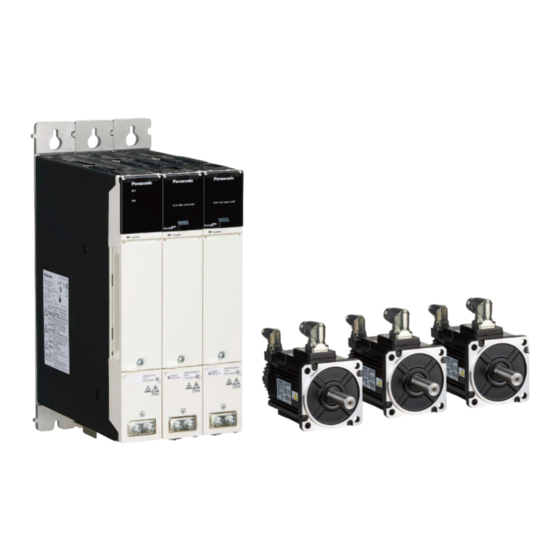
Panasonic MINAS A6 Multi Series Operating Instructions Manual
Ac servo motor & driver
Hide thumbs
Also See for MINAS A6 Multi Series:
- Operating instructions manual (560 pages) ,
- Technical reference (306 pages) ,
- Reference specifications (70 pages)
Table of Contents
Advertisement
Quick Links
Advertisement
Table of Contents

Related Manuals for Panasonic MINAS A6 Multi Series


Summary of Contents for Panasonic MINAS A6 Multi Series
- Page 2 Thank you for purchasing Digital AC Servo Motor & Driver, MINAS A6 Multi series. This instruction manual contains information necessary to correctly and safely use the MINAS A6 Multi series motor and driver. By reading this instruction manual, you will learn how to identify the model of the motor and driver that will be best suitable your application, how to wire and set up them, how to set parameters, and how to locate possible cause of symptom and to take corrective action.
-
Page 3: Related Documents
Scope Scope ◼ System over view of MINAS A6 Multi ◼ Related documents Manual Name REFERENCE SPECIFICATIONS - Power supply module and Driver module - TECHNICAL REFERENCE - Function Specification - TECHNICAL REFERENCE - EtherCAT Communication Specification - TECHNICAL REFERENCE - Safety Installation Manual - TECHNICAL REFERENCE - PANATERM for Safety Programming Manual - (Note) See our Web site for the above documents. - Page 4 • All rights reserved. No part of this publication may be reproduced or transmitted in any form without prior permission. • Industrial Device Business Division, Panasonic Industry Co., Ltd. reserves the right to make modifications and improvements to its products and/or documentation, including specifications and software, without prior notice.
-
Page 5: Table Of Contents
Table of contents Table of contents 1. Before Using the Products ..............1-1 Power supply module ....................1-2 1.1.1 Check of the Model ....................... 1-2 1.1.2 Power supply module ....................1-3 1.1.3 Parts Description ......................1-4 1.1.4 Front panel ........................1-5 1.1.5 Accessories (included connectors) ................ - Page 6 Table of contents 2.2.2 Wire processing ......................2-6 2.2.3 Specifications of Motor Angled receptacles and Encoder Angled receptacles ..... 2-8 2.2.4 Assembly instructions ....................2-9 2.2.4.1 B2CF and BLF series / Symbol [X2], [X4], [X5], [X101] ........2-9 2.2.4.2 BUF series / Symbol [X11], [X102], [X103] ............2-11 2.2.4.3 BVFL series / Symbol [X105] ................
- Page 7 Table of contents 4.2.3 MGMF ........................... 4-7 4.2.4 MHMF ..........................4-8 Time characteristics (our standard servo driver) ............4-9 Dimensions ......................4-10 4.4.1 Driver module ......................4-10 4.4.2 Power supply module ....................4-11 4.4.3 Motor ........................... 4-12...
-
Page 8: Safety Precautions
Safety Precautions Safety Precautions The following explanations are for things that must be observed in order to prevent harm to people and damage to property. • Misuses that could result in harm or damage are shown as follows, classified according to the degree of potential harm or damage. - Page 9 Safety Precautions Do not touch the motor, servo driver, heat sink, regenerative Failure to observe this instruction resistor and dynamic brake resister, since they become very could result in burns. hot. Failure to observe this instruction Do not drive the motor with external power. could result in fire.
- Page 10 Safety Precautions Do not hold the motor cable or motor shaft during the Failure to observe this instruction transportation. could result in injuries. Failure to observe this instruction Don't drop or cause topple over of something during could result in injuries and transportation or installation.
- Page 11 Safety Precautions Using it for transportation of the Use the eye bolt of the motor for transportation of the motor machine will cause personal injury only, and never use this for transportation of the machine. or malfunction. Adjust the motor and driver ambient environmental condition Failure to heed these to match the motor operating temperature and humidity.
-
Page 12: Disposal Precautions
Safety Precautions ◼ Disposal Precautions • The Product shall be treated as Industrial Waste when you dispose. • When you dispose the batteries, observe any applicable regulations or laws after insulating them with the tape. ◼ Cautions for Proper Use •... -
Page 13: Notes On Maintenance And Inspection
Safety Precautions Routine maintenance and inspection of the driver and motor are essential for the proper and safe operation. Notes on Maintenance and Inspection (1) Turn on and turn off should be done by operators or inspectors themselves. When establishing a system using safety functions, completely understand the applicable safety standards and the operating instruction manual or technical documents for the product. - Page 14 Safety Precautions Guideline for Parts Replacement Use the table below for a reference. Parts replacement cycle varies depending on the actual operating conditions. Defective parts should be replaced or repaired when any error have occurred. Disassembling for inspection and repair should be carried out only by authorized dealers or service company.
- Page 15 Safety Precautions xiii...
-
Page 17: Before Using The Products
Before Using the Products... -
Page 18: Power Supply Module
Before Using the Products 1.1 Power supply module 1.1.1 Check of the Model Contents of Name Plate ◼ Model Designation ◼ Serial number The values of the serial number part of the lot number range from 1 to 33999. On the rating plate, it is indicated in four digits as in the format shown below. -
Page 19: Power Supply Module
1.1 Power supply module 1.1.2 Power supply module Model No. Size Mains Power Supply Input Rated output (Note 1) MADMPN14 3-phase 380 to 480 V AC 15 kW MBDMPN24 3-phase 380 to 480 V AC 30 kW (Note 1) The total motor rated output must be selected so that it is less than or equal to the listed value. See “1.5.1 Power supply / Driver”... -
Page 20: Parts Description
Before Using the Products 1.1.3 Parts Description A-size B-size • See page 2-4 for cable. • Do not press on the cover plate of the wiring terminal. -
Page 21: Front Panel
1.1 Power supply module 1.1.4 Front panel Item Status Content RDY status lamp (green) Main power supply established Main power off ERR status lamp (red) Power supply module error detection Blinking No power supply module error/warning detection No power supply module error/no warning 1.1.5 Accessories (included connectors) Quantity[pcs] Connector... -
Page 22: Specifications
Before Using the Products 1.1.6 Specifications Power supply module basic specifications Item Parameter Unit Specification Model No. MADMPN14 MBDMPN24 Model Frame Size (Note 1) A-size B-size Rated Output Power Input Voltage 3-phase AC 380 to 480 -15%, +10% Input current Power capacity (Note 2) Mains Power Supply Input... -
Page 23: Driver Module
1.2 Driver module 1.2 Driver module 1.2.1 Check of the Model Contents of Name Plate ◼ Model Designation ◼ Serial number The values of the serial number part of the lot number range from 1 to 33999. On the rating plate, it is indicated in four digits as in the format shown below. - Page 24 Before Using the Products ◼ Front panel The values of the Safety ID range from 0000050000 to 4294967295. When accessing the driver module using “PANATERM for safety” via Ethernet/EOE, Safety ID is needed. The access method to the driver module by “PANATERM for safety” is shown below. 1.
-
Page 25: Driver Module
1.2 Driver module 1.2.2 Driver module EtherCAT Product Code Rated output of applicable motor per Model No. Conformance Size DC link input (Note 1) 1-axis (Note 3) Test (Note 2) ✓ MADM2A4KBX 1652850735 0.4 to 0.75 kW ✓ MADM2A6KBX 1652850736 0.75 to 1.5 kW 537 to 679 V DC ✓... -
Page 26: Parts Description
Before Using the Products 1.2.3 Parts Description A-size B-size • See page 2-4 for cable. • Do not press on the cover plate of the wiring terminal. 1-10... -
Page 27: Front Panel
1.2 Driver module 1.2.4 Front panel Front panel close state Front panel open state 1-11... -
Page 28: Accessories (Included Connectors)
Before Using the Products 1.2.5 Accessories (included connectors) Quantity[pcs] Connector Manufacturer Manufacturer part number A-size B-size Weidmüller Interface GmbH I/O signal connector 2593030000 & Co. KG Weidmüller Interface GmbH Safety I/O signal connector 2593050000 & Co. KG Weidmüller Interface GmbH X105 Motor output connector 2590720000... -
Page 29: Specifications
Panasonic serial (Note 4) 2nd Encoder Panasonic serial, ABZ, EnDat2.2, SSI Safe Torque Off (STO), Safe Stop 1 (SS1), Safe Stop 2 (SS2), Safe Operating Stop 1 (SOS), Safe Limited Acceleration (SLA), Safe Acceleration Range (SAR), Safe Limited Speed (SLS), Safe Speed Range... - Page 30 Before Using the Products Specification Item Parameter Unit MADM2A4KBX MADM2A6KBX MADM2AAKBX MBDM1ABKBX EtherCAT (CoE, EoE) Position control: Profile position mode (pp), Cyclic synchronous position mode (csp), Homing mode (hm) Velocity control: Profile velocity mode (pv), Cyclic synchronous velocity mode Industrial Ethernet (csv) Network Torque profile mode (tq), Cyclic synchronous torque mode...
-
Page 31: Motor
1.3 Motor 1.3 Motor Model number Rated input voltage/current Rated output Rated frequency Ratedrotational speed Serial number Example: 1 9 0 8 0 0 0 1 Z Standard mark Lot number QR code Month of production Country of origin Year of production (Lower 2 digit of AD year)... -
Page 32: Notice About China Rare Earth Magnet For This Motor
Before Using the Products ◼ Serial numbers (Production numbers) The serial number of a motor nameplate means as follows: Ex.: SER No. 0001 Christian year Production month Serial number 1.3.1 Notice about China Rare earth magnet for this motor This motor uses the Chinese rare earth magnet. The patent's licenser limits the magnet and it's motor's distributed region. -
Page 33: Check Of The Combination Of The Driver And The Motor
1.4 Check of the Combination of the Driver and the Motor 1.4 Check of the Combination of the Driver and the Motor 1.4.1 Combination of Power supply module and Driver module The maximum number of driver modules and connected motors are limited by some terms below. Total rated output of the connected motors The sum of the rated output of connected motors should be kept equal or less than the rated output of power supply module. -
Page 34: Combination Of Driver Module And Motor
Before Using the Products 1.4.2 Combination of Driver module and Motor Applicable Driver Maximum motor part Motor rated Driver module Input voltage module Driver module output per axis number output input power frame part number DC (V) *** is motor symbol specification MHMF044****... -
Page 35: Installation
1.5 Installation 1.5 Installation 1.5.1 Power supply / Driver Installation Place • Install the driver in a control panel enclosed in noncombustible material and placed indoor where the product is not subjected to rain or direct sunlight. The products are not waterproof. •... - Page 36 Before Using the Products Temperature around the drive The temperature around the servo drive should be measured at a position 50 mm away from the side or bottom surface of the drive. If it is impossible to measure the temperature at a position 50 mm away from it, perform measurement at the midpoint in the clearance between the obstacle and the drive.
- Page 37 1.5 Installation Protection time curve for overload condition is shown below. The curve is an example of step output from 0 % to certain current. Output current overload protection for power supply module will be occured when the output time exceed the curve. - Protection time curve for overload condition Make sure that overload protection does not work by running continuously on the actual machine.
-
Page 38: Motor
Before Using the Products 1.5.2 Motor Installation Place • Indoors, where the products are not subjected to rain or direct sun beam. The products are not waterproof. • Where the products are not subjected to corrosive atmospheres such as hydrogen sulfide, sulfurous acid, chlorine, ammonia, sulfur, chloric gas, sulfuric gas, acid, alkaline and salt and so on, and are free from splash of inflammable gas. -
Page 39: Permissible Load At Output Shaft
1.6 Permissible Load at Output Shaft 1.6 Permissible Load at Output Shaft Assembling precision • In accordance with the outline drawings. The axial runout is measured in the lateral direction of the shaft. The flange surface squareness and spigot eccentricity are measured in the vertical direction of the shaft. •... - Page 40 Before Using the Products When a load position is changed, calculate allowable radial load P by the following relational expression, using load position’s distance L from the mounting flange surface, and set the load below a value resulting from such calculation.
-
Page 41: Preparation
Preparation... -
Page 42: Conformance To International Standards
A6 enconder A6 enconder A6 enconder A6 enconder 2nd encoder None None Third party Third party (Panasonic format) (Panasonic format) ABZ ABZ EnDat2.2 (non-safety) EnDat2.2 (non-safety) SSI SSI Safety Integrity Level SIL 3 / maximum SIL 3... -
Page 43: Eu Directive / Uk Regulation
2.1 Conformance to international standards 2.1.3 EU Directive / UK Regulation We achieve compliance with the standards related to the Low Voltage Directive / Regulation, so that the embedded machines and devices can easily comply with the EU Directive / UK Regulation. Compliance with the EMC Directive / Regulation The servo drive and the servo motor are not intended to be used on a low-voltage public network which supplies residential premises;... - Page 44 Preparation Insulated power supply for control (24 V) Recommended components: Manufacturer Manufacturer Applicable module Home page part number A - size OMRON Corporatoin S8VK-S series https://www.fa.omron.co.jp B - size Noise filter 1 When using multiple units of servo drive and installing one noise filter collectively in the power supply section, consult with the noise filter manufacturer.
-
Page 45: Radio Waves Act Of South Korea
2.1 Conformance to international standards Grounding • To avoid electric shocks, be sure to connect the protective earth terminal ( ) of the servo drive and the protective earth (PE) of the control panel. • Avoid co-fastening for the connection to the protective earth terminal ( ). -
Page 46: System Configuration And Wiring
Select wire suitable for the motor Protective earth (Note 1) The above wiring length is the maximum value under the evaluation environment of Panasonic.It does not guarantee the operation under the working environment of the customer. (Note 2) Select wire suitable for the actual current. - Page 47 2.2 System Configuration and Wiring For wiring the connectors, ferrule terminal is recommended. Examples of ferrule terminals (Weidmüller Interface GmbH & Co. KG) are shown below. See datasheet of manufacturers for details. Make sure to use tools recommended by manufacturers. ◼...
-
Page 48: Specifications Of Motor Angled Receptacles And Encoder Angled Receptacles
Preparation ◼ Recommended crimping tools Manufacturer part number Ordering number (Weidmüller) Applicable wire cross section (mm PZ 3 0567300000 0.50 to 6.0 PZ 4 9012500000 0.50 to 4.0 PZ 6/5 9011460000 0.25 to 6.0 PZ 6Roto L 1444050000 0.14 to 6.0 PZ 10 HEX 1445070000 0.14 to 10... -
Page 49: Assembly Instructions
2.2 System Configuration and Wiring 2.2.4 Assembly instructions 2.2.4.1 B2CF and BLF series / Symbol [X2], [X4], [X5], [X101] ◼ External device signal input: X2 (B2CF 3.50) Manufacturer part number Ordering number (Weidmüller) Wire cross section (mm ) Contact surface (mm) H0,25/12 HBL 9025760000 0.25... - Page 50 Preparation ◼ Connecting flexible conductors 1. Open the contact point by activating the push-button (slider/pusher). 2. Insert stranded conductors, without crimped-on wire-end ferrules. 3. Remove tool from push-button (slider/pusher). 2-10...
-
Page 51: Buf Series / Symbol [X11], [X102], [X103]
2.2 System Configuration and Wiring 2.2.4.2 BUF series / Symbol [X11], [X102], [X103] ◼ DC24 V control power supply: X11, Main power supply: X102, Regenerative braking resistor connector: X103 (BUF 10.16IT) Manufacturer part number Ordering number (Weidmüller) Wire cross section (mm ) Contact surface (mm) H2,5/25D BL 9019180000... -
Page 52: Bvfl Series / Symbol [X105]
Preparation 2.2.4.3 BVFL series / Symbol [X105] ◼ Motor output connector (Brake): X105 (BVFL 7.62HP Hybrid) Manufacturer part number Ordering number (Weidmüller) Wire cross section (mm ) Contact surface (mm) H0,25/12 HBL 9025760000 0.25 H0,34/12 TK 9025770000 0.34 H0,5/14 OR 0690700000 0.50 H0,75/14 W... -
Page 53: Precautions For Wiring
2.2 System Configuration and Wiring 2.2.5 Precautions for wiring Wiring the connectors and the terminal blocks • Insert the connector securely until it is locked. • Apply power supply voltage as specified in the rating plate. • High voltage is applied to power connectors X102, X103, X104. Make sure not to touch them. There is a risk to get an electric shock. - Page 54 Preparation Wiring to the power connector and the terminal block Connectors X1 to X10 are used for the secondary side circuit. They need to be isolated from the primary side power supply. Do not connect to the same power supply. ◼...
- Page 55 2.2 System Configuration and Wiring • Insert the connector securely until it is locked. • Apply power supply voltage as specified in the rating plate. • Do not ground or short-circuit the motor output terminals (U, V, and W) each other. •...
-
Page 56: Regenerative Braking Resistor
Preparation 2.3 Regenerative braking resistor 2.3.1 Regenerative braking resistor selection Select a regenerative resistor with values in the following table below. Model No. Resistor value 15 Ω, 10 kW MADMPN14 8 Ω, 20 kW MBDMPN24 The power capacity of this resistor is a design value that assume continuous regeneration, so select it according to actual use conditions. -
Page 57: Compliance With The Ul Standard
Thermostat signal input is also available. • Optional parts shown below are available. Use them by combination, when rated power of regenerative resistor is not enough. Specifications Rated power Panasonic Manufacturer Cable core Activation temperature of (reference) (Note 1) option number... -
Page 58: Dynamic Brake
Preparation 2.4 Dynamic brake Driver module (sizes A to B) has a dynamic brake built in for emergency stop. The dynamic brake can be operated in the following cases. (1) When power supply is turned off (2) When the servo is turned off (3) When the protective function is operated (4) When drive prohibiting input (POT, NOT) of connector X4 is operated During deceleration in the above cases (1) to (4) or after the stop of the servo drive, whether the dynamic... -
Page 59: Connection
Connection... -
Page 60: Common To Modules
Connection 3.1 Common to modules 3.1.1 Cross communication connector X1, X1A, X1B Pin No. Symbol Polarity Description DATA+ IN/OUT DATA- IN/OUT SYNC+ IN/OUT Only for system-internal usage/communication. SYNC- IN/OUT • Connect the Cross communication cable from X1 to X1A of the next driver module. •... -
Page 61: Power Supply Module
3.2 Power supply module 3.2 Power supply module 3.2.1 External device signal input connector X2 Pin No. Symbol Polarity Description DIN1 Digital input 1 for magnet contactor feedback DIN2 Digital input 2 for braking resistor temperature feedback Frame ground COM1 Digital input common 1 COM2 Digital input common 2... -
Page 62: Contactor Control Output Connector X101
Connection 3.2.2 Contactor control output connector X101 Pin No. Symbol Polarity Description Magnet contactor output 1 Magnet contactor output 2 ◼ Terminal pin assignment of Contactor control output connector X101 When magnet contactor is not used, change the parameter setting (PSM Pr. 04). ◼... -
Page 63: Dc24 V Control Power Supply Connector X11
3.2 Power supply module 3.2.3 DC24 V control power supply connector X11 Pin No. Symbol Polarity Description External ground +24 V +24 V Control supply ◼ Terminal pin assignment of DC24 V control power supply connector X11 3.2.4 Main power supply connector X102 Pin No. -
Page 64: Driver Module
Connection 3.3 Driver module 3.3.1 I/O signal connector X4 Pin No. Symbol Polarity Description General purpose digital input General purpose digital input General purpose digital input General purpose digital input SI-COM COMP1+ Position comparison output1+ COMP2+ Position comparison output2+ SO1+ General purpose digital output SO2+ General purpose digital output... - Page 65 3.3 Driver module ◼ i-1: General purpose input Source output connection Sink output connection Terminal No. 1, 2, 3, 4, 11, 12, 13, 14 Terminal No. 5 ◼ o-1: General purpose output Source input connection Sink input connection Terminal No. 8, 9 Terminal No.
-
Page 66: Safety I/O Connector X5
Connection 3.3.2 Safety I/O connector X5 Pin No. Symbol Polarity Description Frame ground BRKO1- Safety brake output 1- BRKO1+ Safety brake output 1+ SDO2A Safety output 2A SDO1A Safety output 1A *Do NOT connect. *Do NOT connect. *Do NOT connect. *Do NOT connect. - Page 67 3.3 Driver module Safety input for sink output connection When connecting the sink output circuit to the safety input, connect the positive terminal of the external power supply DC 24 V to the common input (COMA, COMB). ◼ i-1: Grouped Safety Digital input (without Diagnostic test pulse) Terminal No.
- Page 68 Connection ◼ i-3: Grouped Safety Digital input (with Diagnostic test pulse) Terminal No. 17 Terminal No. 10 Terminal No. 12, 13, 14, 15 Terminal No. 16 Terminal No. 27 Terminal No. 29, 30, 31, 32 Terminal No. 33 Terminal No. 34 ◼...
- Page 69 3.3 Driver module Safety input for source output connection When connecting the source output circuit to the safety input, connect the negative terminal of the external power supply DC 24 V to the common input (COMA, COMB). ◼ i-5: Grouped Safety Digital input (without Diagnostic test pulse) Terminal No.
- Page 70 Connection ◼ i-7: Grouped Safety Digital input (with Diagnostic test pulse) Terminal No. 17 Terminal No. 10 Terminal No. 12, 13, 14, 15 Terminal No. 16 Terminal No. 27 Terminal No. 29, 30, 31, 32 Terminal No. 33 Terminal No. 34 ◼...
- Page 71 3.3 Driver module Safety output ◼ o-1: Safety output Terminal No. 17 Terminal No. 4, 5 Terminal No. 21, 22 Terminal No. 34 * When driving the relay directly, mount a diode in parallel with the relay in the direction shown in the above figure. ◼...
-
Page 72: Ethercat Communication Connector X6A, X6B
Connection 3.3.3 EtherCAT communication connector X6A, X6B Pin No. Symbol Polarity Description TX/RX+ OUT/IN Network output / input + TX/RX- OUT/IN Network output / input - RX/TX+ IN/OUT Network input / output + RX/TX- IN/OUT Network input / output - Shell Frame ground * Be sure to use shielded twisted pair (STP) compatible with category 5e or higher in TIA/EIA-568. -
Page 73: 1St Encoder Connector X9 (X9A, X9B)
3.3 Driver module 3.3.4 USB connector (for motor setup), USB connector (for safety) X7, X8 Pin No. Symbol Polarity Description VBUS VBUS IN/OUT USB signal terminal IN/OUT USB signal terminal For manufacturer Signal ground * The connector type is USB mini-B. ◼... -
Page 74: 2Nd Encoder Connector X10 (X10A, X10B)
Connection 3.3.6 2nd Encoder connector X10 (X10A, X10B) Pin No. Symbol Polarity Description EX5V 2nd Encoder power output (Panasonic / ABZ) EX0V 2nd Encoder ground EXPS IN/OUT Serial signal non-inverting input/output /EXPS IN/OUT Serial signal inverting input/output A-phase signal non-inverting input... -
Page 75: Motor Output Connector X105 (X105A, X105B)
3.3 Driver module 3.3.7 Motor output connector X105 (X105A, X105B) Pin No. Symbol Polarity Description Motor output (W phase) Motor output (V phase) Motor output (U phase) Protective Earth BRK- Brake output- BRK+ Brake output+ ◼ Pin assignment of Motor output connector X105A, X105B * X105A connector is for A axis, and X105B connector is for B axis. - Page 76 Connection 3-18...
-
Page 77: Supplement
Supplement... -
Page 78: Specification
Supplement 4.1 Specification 4.1.1 Rotary encoder specification • Absolute encoder 23bit • Batteryless absolute encoder 23bit • Precautions for battery exchange in the case of absolute encoder. When you exchange the battery, please hold the main power of encoder in the ON position (as supplying the encoder with 5 V) and exchange the battery. - Page 79 4.1 Specification MDMF Applicable motor MDMF104○1□△M Items Units MDMF154○1□△M MDMF304○1□△M MDMF404○1□△M MDMF504○1□△M MDMF204○1□△M Static friction torque (Note 1) N·m 13.7 or more 22.0 or more 25.0 or more 44.1 or more Rotary part inertia (Note 2) kg·m 1.12 Armature pull in time (Note 2) 100 or less 110 or less 80 or less...
-
Page 80: Surge Absorber For Motor Brake
Supplement MHMF Applicable motor MHMF204○1□△M Items Units MHMF104○1□△M MHMF304○1□△M MHMF504○1□△M MHMF154○1□△M MHMF404○1□△M Static friction torque (Note 1) N·m 13.7 or more 25.0 or more 44.1 or more Rotary part inertia (Note 2) kg·m 1.12 Armature pull in time (Note 2) 100 or less 80 or less 150 or less... -
Page 81: Motor Characteristics
4.2 Motor Characteristics 4.2 Motor Characteristics 4.2.1 MSMF MSMF104 MSMF154 MSMF204 MSMF304 MSMF404 MSMF504 ○1□△M ○1□△M ○1□△M ○1□△M ○1□△M ○1□△M Items Units Without With Without With Without With Without With Without With Without With brake brake brake brake brake brake brake brake brake... -
Page 82: Mdmf
Supplement 4.2.2 MDMF MDMF104 MDMF154 MDMF204 MDMF304 MDMF404 MDMF504 ○1□△M ○1□△M ○1□△M ○1□△M ○1□△M ○1□△M Items Units Without With Without With Without With Without With Without With Without With brake brake brake brake brake brake brake brake brake brake brake brake Rated output Rated speed... -
Page 83: Mgmf
4.2 Motor Characteristics 4.2.3 MGMF MGMF094 MGMF134 MGMF184 MGMF244 MGMF294 MGMF444 ○1□△M ○1□△M ○1□△M ○1□△M ○1□△M ○1□△M Items Units Without With Without With Without With Without With Without With Without With brake brake brake brake brake brake brake brake brake brake brake brake... -
Page 84: Mhmf
Supplement 4.2.4 MHMF MHMF104 MHMF154 MHMF204 MHMF304 MHMF404 MHMF504 ○1□△M ○1□△M ○1□△M ○1□△M ○1□△M ○1□△M Items Units Without With Without With Without With Without With Without With Without With brake brake brake brake brake brake brake brake brake brake brake brake Rated output Rated speed... -
Page 85: Time Characteristics (Our Standard Servo Driver)
4.3 Time characteristics (our standard servo driver) 4.3 Time characteristics (our standard servo driver) MSMF 104, 154, 204, 304, 404, 504 MDMF 104, 154, 204, 304 404, 504 MGMF 094, 134, 184 244, 294, 444 MHMF 104, 154, 204 304, 404, 504 •... -
Page 86: Dimensions
Supplement 4.4 Dimensions 4.4.1 Driver module A-size * Recommended screw : M6 Tightening torque 4.68 N·m to 5.72 N·m B-size * Recommended screw : M6 Tightening torque 4.68 N·m to 5.72 N·m 4-10... -
Page 87: Power Supply Module
4.4 Dimensions 4.4.2 Power supply module A-size * Recommended screw : M6 Tightening torque 4.68 N·m to 5.72 N·m B-size * Recommended screw : M6 Tightening torque 4.68 N·m to 5.72 N·m 4-11... -
Page 88: Motor
Supplement 4.4.3 Motor MSMF ◼ 23bit Motor output(kW) MSMF104 MSMF154 MSMF204 MSMF304 MSMF404 MSMF504 Motor model L1□△M L1□△M L1□△M L1□△M L1□△M L1□△M Without Brake 157.5 176.5 With Brake 184.5 203.5 81.3 81.3 81.3 81.3 81.3 81.3 101.2 101.2 101.2 101.5 106.5 106.5 Without Brake... - Page 89 4.4 Dimensions ◼ 23bit-Batteryless Motor output(kW) MSMF104 MSMF154 MSMF204 MSMF304 MSMF404 MSMF504 Motor model A1□△M A1□△M A1□△M A1□△M A1□△M A1□△M Without Brake 145.5 194.5 213.5 248.5 With Brake 172.5 219.5 241.5 276.5 81.3 81.3 81.3 81.3 81.3 81.3 101.2 101.2 101.2 101.5 106.5...
- Page 90 Supplement MDMF ◼ 23bit Motor output(kW) MDMF104 MDMF154 MDMF204 MDMF304 MDMF404 MDMF504 Motor model L1□△M L1□△M L1□△M L1□△M L1□△M L1□△M Without Brake With Brake 114.3 114.3 81.3 81.3 81.3 81.3 81.3 81.3 106.5 106.5 106.5 106.5 129.8 129.8 Without Brake With Brake 13.5 13.5...
- Page 91 4.4 Dimensions ◼ 23bit-Batteryless Motor output(kW) MDMF104 MDMF154 MDMF204 MDMF304 MDMF404 MDMF504 Motor model A1□△M A1□△M A1□△M A1□△M A1□△M A1□△M Without Brake 127.5 141.5 155.5 183.5 169.5 184.5 With Brake 155.5 169.5 183.5 211.5 198.5 213.5 114.3 114.3 81.3 81.3 81.3 81.3 81.3...
- Page 92 Supplement MGMF ◼ 23bit Motor output(kW) MGMF094 MGMF134 MGMF184 MDMF244 MGMF294 MGMF444 Motor model L1□△M L1□△M L1□△M L1□△M L1□△M L1□△M Without Brake With Brake 114.3 114.3 114.3 81.3 81.3 81.3 81.3 81.3 81.3 106.5 106.5 106.5 129.8 129.8 129.8 Without Brake With Brake 13.5 13.5...
- Page 93 4.4 Dimensions ◼ 23bit-Batteryless Motor output(kW) MGMF094 MGMF134 MGMF204 MGMF244 MDMF294 MGMF444 Motor model A1□△M A1□△M A1□△M A1□△M A1□△M A1□△M Without Brake 127.5 141.5 155.5 169.5 169.5 184.5 With Brake 155.5 169.5 183.5 198.5 198.5 213.5 114.3 114.3 114.3 81.3 81.3 81.3 81.3...
- Page 94 Supplement MHMF ◼ 23bit Motor output(kW) MHMF104 MHMF154 MHMF204 MHMF304 MHMF404 MHMF504 Motor model L1□△M L1□△M L1□△M L1□△M L1□△M L1□△M Without Brake 192.5 208.5 With Brake 221.5 237.5 114.3 114.3 114.3 114.3 81.3 81.3 81.3 81.3 81.3 81.3 116.2 116.2 139.2 139.2 139.2...
- Page 95 4.4 Dimensions ◼ 23bit-Batteryless Motor output(kW) MHMF104 MHMF154 MHMF204 MHMF304 MHMF404 MHMF504 Motor model A1□△M A1□△M A1□△M A1□△M A1□△M A1□△M Without Brake 155.5 169.5 169.5 184.5 With Brake 183.5 197.5 198.5 213.5 114.3 114.3 114.3 114.3 81.3 81.3 81.3 81.3 81.3 81.3 116.2...
-
Page 97: Cautions For Proper Use
Cautions for Proper Use Cautions for Proper Use • Practical considerations for exporting the product or assembly containing the product When the end user of the product or end use of the product is associated with military affair or weapon, its export may be controlled by the Foreign Exchange and Foreign Trade Control Law. -
Page 98: Warranty Period
Warranty Warranty period • Panasonic warrants 12 months from date of delivery or maximum 18 months from date of manufacture whichever comes first.. For a motor with brake, the axis accelerated and decelerated more times than the specified limit is not covered by warranty. -
Page 99: After-Sale Service (Repair)
Please note them in the space provided and keep for future reference. Model No. Serial No. Date of purchase Store name Phone ( Industrial Device Business Division, Panasonic Industry Co., Ltd. 1-1, Morofuku 7-chome, Daito, Osaka 574-0044, Japan ��Panasonic Industry Co., Ltd. 2020-2024 IMF16 N0121-2084...
Need help?
Do you have a question about the MINAS A6 Multi Series and is the answer not in the manual?
Questions and answers