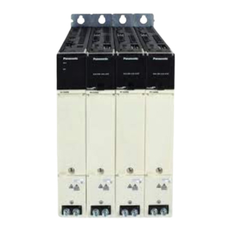
Panasonic MINAS A6 Multi Series Reference Specifications
Hide thumbs
Also See for MINAS A6 Multi Series:
- Operating instructions manual (560 pages) ,
- Technical reference (306 pages) ,
- Reference specifications (70 pages)
Table of Contents
Advertisement
Quick Links
REFERENCE
SPECIFICATIONS
MODEL
Product Name. Book style servo system
Product No.
Motion Control Business Unit,Industrial Device Business Division
Panasonic Industry Co., Ltd.
7-1-1 Morofuku, Daito-City, Osaka 574-0044, Japan
MINAS A6 Multi Series
- Driver module section
Issued on Apr. 11, 2019
Revised on Aug. 5 2024
No. SX-DSV03454
Advertisement
Table of Contents

Related Manuals for Panasonic MINAS A6 Multi Series


Summary of Contents for Panasonic MINAS A6 Multi Series
- Page 1 REFERENCE SPECIFICATIONS MODEL Product Name. Book style servo system Product No. MINAS A6 Multi Series - Driver module section Issued on Apr. 11, 2019 Revised on Aug. 5 2024 Motion Control Business Unit,Industrial Device Business Division Panasonic Industry Co., Ltd.
- Page 2 No. SX-DSV03454 Revisions Page Date Rev. Changed point Description Date of Revision Signed Changed drawing Reason for change, change contents submission Feb. 4, 2019 Initial Release Y.Shimogaki Apr. 11, 2019 Page 1 Add the product code for 2 encoder Y.Shimogaki Page 6 Add the product weight Y.Shimogaki...
- Page 3 No. SX-DSV03454 Page Date Rev. Changed point Description Date of Revision Signed Changed drawing Reason for change, change contents submission 9-1. Update the table (Delete “EN 60204-1”) S. Tamaru Aug. 5, 2024 Page 37 Reference Specifications - MINAS A6 Multi...
-
Page 4: Table Of Contents
No. SX- DSV03454 Contents 1. Scope ..................................1 2. Model Designation ............................... 3 3. Product Line-up ..............................3 3-1 Driver module .............................. 3 3-2 Accessories (included connectors) ....................... 4 4. Specifications ............................... 5 5. Appearance and name of each part ........................7 6. - Page 5 No. SX- DSV03454 11. Life span ................................47 11-1 Expected life span of the power supply and driver module ..............47 11-2 Standard life span ............................. 47 11-2-1 In-rush current protection circuit ..................... 47 11-2-2 Cooling fan ............................47 12. Warranty ................................48 12-1 Warranty period ............................
-
Page 6: Scope
No. SX- DSV03454 -1- 1. Scope The contents of this specification document are related to the Book style servo system MINAS A6 Multi series manufactured by the Motion Control Business Unit, Industrial Device Business Division, Panasonic Industry Co., Ltd. This product is intended for industrial equipment. It cannot be used for any other purposes (e.g. for household). - Page 7 • All rights reserved. No part of this publication may be reproduced or transmitted in any form without prior permission. • Motion Control Business Unit, Panasonic Industry Co., ltd. reserves the right to make modifications and improvements to its products and/or documentation, including specifications and software, without prior notice.
-
Page 8: Model Designation
No. SX- DSV03454 -3- 2. Model Designation Each segment of the product number has the following meaning. Type A : A - size MADM2A4KBX** B : B - size Series M : MINAS A6 Multi Module Type 1 : 1-axis Driver module 2 : 2-axis Driver module Safety Designation A : Advanced Safety... -
Page 9: Accessories (Included Connectors)
No. SX- DSV03454 -4- 3-2 Accessories (included connectors) Quantity[pcs] Connector Manufacturer Manufacturer part number size size Weidmüller Interface B2CF 3.50/20/180LR SN I/O signal connector GmbH & Co. KG OR BX PRT Weidmüller Interface B2CF 3.50/34/180LR SN Safety I/O signal connector GmbH &... -
Page 10: Specifications
1st Encoder Panasonic serial (*Note 4) 2nd Encoder Panasonic serial, ABZ, EnDat2.2, SSI Safe Torque Off (STO), Safe Stop 1 (SS1), Safe Stop 2 (SS2), Safe Operating Stop 1 (SOS), Safe Limited Acceleration (SLA), Safe Acceleration Safety functions Range (SAR), Safe Limited Speed (SLS), Safe Speed Range (SSR), Safe Limited... - Page 11 No. SX- DSV03454 -6- Environmental conditions Operation temperature 0 to 40 °C (without freezing) Temperature Storage temperature -20 to 55 °C (maximum temperature guarantee: 70 °C, 72 hours, without condensation) Humidity Working/storage humidity 20 to 85 %RH (without condensation) Working ambient condition Altitude 1,000 m above sea level or less...
-
Page 12: Appearance And Name Of Each Part
No. SX- DSV03454 -7- 5. Appearance and name of each part Driver module/A - size X5: Safety I/O signal connector (cable side) X4: I/O signal connector (cable side) 2593050000 (Weidmüller) 2593030000 (Weidmüller) X1A, X1B: Cross communication connector (cable side) 2349354-3 (TE Connectivity) X4: I/O signal connector X1A, X1B: Cross communication connector 5555154-1 (TE Connectivity) - Page 13 No. SX- DSV03454 -8- Example of a rating plate • Side cover Model number Serial number QR code Example: P 2 0 0 8 0 0 0 1 Z Standard Lot number mark Month of Year of production production (Lower 2 digit of AD year) Input/Output voltage Country of Number of phase...
- Page 14 No. SX- DSV03454 -9- • Front panel MADM2AAKBX Safety ID 400 V 1234567890 A19080001 The values of the Safety ID range from 000005000 to 4294967295. When accessing the driver module using “PANATERM for safety” via Ethernet/EOE, Safety ID is needed. The access method to the driver module by “PANATERM for safety”...
- Page 15 No. SX- DSV03454 -10- Front panel • Front panel open state 2 digit 7-segment LED Node address setting for USB connector EtherCAT communication 0x10 (for motor setup) rotary switch(2-digit) Setting range: 0~FF USB connector (for safety) Mode selector button Node address setting for cross communication DIP switch (6 bits)...
-
Page 16: Dimensions
No. SX- DSV03454 -11- 6. Dimensions A - size Unit: mm Reference Specifications - MINAS A6 Multi... - Page 17 No. SX- DSV03454 -12- B - size Unit: mm Reference Specifications - MINAS A6 Multi...
-
Page 18: Configuration Of Connectors And Terminal Blocks
No. SX- DSV03454 -13- 7. Configuration of connectors and terminal blocks 7-1 Cross communication connector X1A, X1B Pin No. Symbol Polarity Description DATA+ IN/OUT DATA- IN/OUT SYNC+ IN/OUT Only for system-internal usage/communication. SYNC- IN/OUT * Use the Cross communication cable included with the product. * Connect the Cross communication cable from X1B to X1A of the next driver module. -
Page 19: I/O Signal Connector X4
No. SX- DSV03454 -14- 7-2 I/O signal connector Pin No. Symbol Polarity Description General purpose digital input General purpose digital input General purpose digital input General purpose digital input SI-COM COMP1+ Position comparison output1+ COMP2+ Position comparison output2+ SO1+ General purpose digital output SO2+ General purpose digital output Frame ground... -
Page 20: Connection Example For I/O Signal Connector
No. SX- DSV03454 -15- 7-2-1 Connection example for I/O signal connector i-1: General purpose input 12 to 24 V 4.7 kΩ 4.7 kΩ 12 to 24 V S : Terminal No. 1, 2, 3, 4, 11, 12, 13, 14 P : Terminal No. 5 o-1: General purpose output 10 Ω... -
Page 21: Safety I/O Connector X5
No. SX- DSV03454 -16- 7-3 Safety I/O connector X5 Pin No. Symbol Polarity Description Frame ground BRKO1- Safety brake output 1- BRKO1+ Safety brake output 1+ SDO2A Safety output 2A SDO1A Safety output 1A *Do NOT connect. *Do NOT connect. *Do NOT connect. -
Page 22: Connection Example For Safety I/O Connector
No. SX- DSV03454 -17- 7-3-1 Connection example for Safety I/O connector (1) Safety input for sink output connection When connecting the sink output circuit to the safety input, connect the positive terminal of the external power supply DC 24 V to the common input (COMA, COMB). i-1: Grouped Safety Digital input (without Diagnostic test pulse) 24 V 10 mA... - Page 23 No. SX- DSV03454 -18- i-3: Grouped Safety Digital input (with Diagnostic test pulse) 24 V 10 mA EXGND 24 kΩ Control Circuit 10 mA EXGND 24 kΩ EXGND P : Terminal No. 17 PA : Terminal No. 10 SA : Terminal No. 12, 13, 14, 15 CA : Terminal No.
- Page 24 No. SX- DSV03454 -19- (2) Safety input for source output connection When connecting the source output circuit to the safety input, connect the negative terminal of the external power supply DC 24 V to the common input (COMA, COMB). i-5: Grouped Safety Digital input (without Diagnostic test pulse) 24 V 10 mA EXGND...
- Page 25 No. SX- DSV03454 -20- i-7: Grouped Safety Digital input (with Diagnostic test pulse) 24 V 10 mA EXGND 24 kΩ Control Circuit 10 mA EXGND 24 kΩ EXGND P : Terminal No. 17 PA : Terminal No. 10 SA : Terminal No. 12, 13, 14, 15 CA : Terminal No.
- Page 26 No. SX- DSV03454 -21- (3) Safety output o-1: Safety output Isolation 24 V Control Circuit EXGND Isolation EXGND EXGND P : Terminal No. 17 OA : Terminal No. 4, 5 OB : Terminal No. 21, 22 G : Terminal No. 34 * When driving the relay directly, mount a diode in parallel with the relay in the direction shown in the above figure.
-
Page 27: Ethercat Communication Connector X6A, X6B
No. SX- DSV03454 -22- 7-4 EtherCAT communication connector X6A, X6B Pin No. Symbol Polarity Description TX/RX+ OUT/IN Network output/input + TX/RX- OUT/IN Network output/input - RX/TX+ IN/OUT Network input/output + RX/TX- IN/OUT Network input/output - Shell Frame ground * Be sure to use shielded twisted pair (STP) compatible with category 5e or higher in TIA/EIA-568. * Auto MDI/MDI-X assigns functions to pin no.1, 2, 3, 6. -
Page 28: Usb Connector (For Motor Setup), Usb Connector (For Safety) X7, X8
No. SX- DSV03454 -23- 7-5 USB connector (for motor setup), USB connector (for safety) X7, X8 Pin No. Symbol Polarity Description VBUS VBUS IN/OUT USB signal terminal IN/OUT USB signal terminal For manufacturer Signal ground *The connector type is USB mini-B. Terminal pin assignment of USB connector (for motor setup) X7, USB connector (for safety) X8 7-6 1 Encoder connector X9 (X9A, X9B) -
Page 29: Nd Encoder Connector X10 (X10A, X10B)
No. SX- DSV03454 -24- 7-7 2 Encoder connector X10 (X10A, X10B) Pin No. Symbol Polarity Description EX5V Encoder power output (Panasonic/ABZ) EX0V Encoder ground EXPS IN/OUT Serial signal non-inverting input/output /EXPS IN/OUT Serial signal inverting input/output A-phase signal non-inverting input... - Page 30 No. SX- DSV03454 -25- Supported encoder types (1 encoder) Supported encoder types Panasonic 23bit multi-turn absolute encoder Supported encoder types (2 encoder) Supported encoder types For feedback scale For safety (Reduplication) Panasonic serial Available Available Available Available EnDat 2.2 Available...
-
Page 31: Motor Output Connector X105 (X105A, X105B)
No. SX- DSV03454 -26- 7-8 Motor output connector X105 (X105A, X105B) Pin No. Symbol Polarity Description Motor output (W phase) Motor output (V phase) Motor output (U phase) Protective Earth BRK- Brake output- BRK+ Brake output+ Pin assignment of Motor output connector X105A, X105B * X105A connector is for A axis, and X105B connector is for B axis. -
Page 32: Power Bus System
No. SX- DSV03454 -27- 7-9 Power bus system Width: 100 mm Driver module Width: 50 mm Driver module Width: 50 mm Driver module Width: 50 mm Power supply module DC Link bus connector MINAS A6 Multi Book style servo system DC24V control power supply Link bus connector 50 mm... -
Page 33: Wiring And System Configuration
Select wire suitable for the motor Protective earth Note 1) The above wiring length is the maximum value under the evaluation environment of Panasonic. It does not guarantee the operation under the working environment of the customer. Note 2) It is necessary to determine the wire diameter considering the 2 encoder specification and wire length. -
Page 34: Wire Processing
No. SX- DSV03454 -29- 8-2 Wire processing For wiring the push-in connectors, ferrule terminal is recommended. Examples of ferrule terminals (Weidmüller Interface GmbH & Co. KG) are shown below. See datasheet of manufacturers for details. Make sure to use tools recommended by manufacturers. I/O signal connector: X4, Safety I/O connector: X5 (B2CF 3.50) Manufacturer Wire diameter... - Page 35 No. SX- DSV03454 -30- Cable-side connector is available shown below. Manufacturer part Panasonic Name Symbol Product type Manufacturer number option number Receptacle 3E206-0100 KV encoder DV0PM20010 connector (X9A, X9B) Shell kit 3E306-3200-008 5745172-1 Shield Kit TE Connectivity Ltd. (Cable dia. range: 8.51 to 9.52 mm)
-
Page 36: Assembly Instructions
No. SX- DSV03454 -31- 8-3 Assembly instructions 8-3-1 B2CF series Connector • I/O signal connector (X4) • Safety I/O connector (X5) Recommended tool • Screwdriver blade 0.4 × 2.5 • Screwdriver blade standard DIN 5264 Connecting solid conductors 1. A stripped solid conductor is simply plugged into the contact point up to the end stop. Connecting conductors with wire-end ferrule 1. -
Page 37: Bvfl Series
No. SX- DSV03454 -32- 8-3-2 BVFL series Connector • Motor output connector (X105A, X105B) <Brake output> See section 8-3-1 for details. <Motor output> Recommended tool • Screwdriver blade 0.6 × 3.5 • Screwdriver blade standard DIN 5264 Connecting flexible conductors 1. -
Page 38: Precautions For Wiring
No. SX- DSV03454 -33- 8-4 Precautions for wiring 8-4-1 Wiring to the power connector and the terminal block A - size EX24 V EGND/EX24 V EXGND TOP Side COMA/COMB EtherCAT IN SDI1A/SDI1B X6A, X6B SDI2A/SDI2B EtherCAT OUT Safety Digital SDI3A/SDI3B Input SDI4A/SDI4B GND/24 V... - Page 39 No. SX- DSV03454 -34- [1] Insert the connector securely until it is locked. [2] Apply power supply voltage as specified in the rating plate. [3] Do not ground or short-circuit the motor output terminals (U, V, and W) each other. [4] High voltage is applied to power connectors X104 X105 .
-
Page 40: Dynamic Brake
No. SX- DSV03454 -35- 8-5 Dynamic brake Driver module (sizes A to B) has a dynamic brake built in for emergency stop. The dynamic brake can be operated in the following cases. [1] When power supply is turned off [2] When the servo is turned off [3] When the protective function is operated [4] When drive prohibiting input (POT, NOT) of connector X4 is operated During deceleration in the above cases [1] to [4] or after the stop of the servo drive, whether the dynamic brake is... -
Page 41: Mounting Direction And Interval
No. SX- DSV03454 -36- 8-6 Mounting direction and interval • Secure the surrounding space for effective cooling. • Install a fan to equalize the temperature in the control panel. • Sizes A to B have a cooling fan on the lower side. •... -
Page 42: Compliance With The International Standards
No. SX- DSV03454 -37- 9. Compliance with the international standards 9-1 List of compatible standards for the servo drive Standard EMC Directive / EN 61000-6-2 EMC Regulation EN 61800-3 Low Voltage Directive / EN 61800-5-1 Low Voltage Regulation EU Directive/ UK Regulation EN ISO 13849-1:2015 (PL e, Cat.4) EN 61508 (SIL 3) -
Page 43: Functional Safety
There is a possibility that content will change depending on the result of the compliance tests. Encoder Safety target and applicable safety functions SIL3, PL e Cat.3/Cat.4 for STO, SBC, Panasonic A6 None encoder SIL2, PL d Cat.3 for SS1, SLS, SSM, SSR •... -
Page 44: Eu Directive / Uk Regulation
No. SX- DSV03454 -39- 9-3 EU Directive / UK Regulation We achieve compliance with the standards related to the Low Voltage Directive / Regulation, so that the embedded machines and devices can easily comply with the EU Directive / UK Regulation. 9-3-1 Compliance with the EMC Directive / Regulation The servo drive and the servo motor are not intended to be used on a low-voltage public network which supplies residential premises;... -
Page 45: Power Supply
No. SX- DSV03454 -40- 9-3-2 Power supply +10 % 400 V AC TN system 3-phase 380 V to 480 V 50/60 Hz -15 % (1) Use them under the environment of overvoltage category III stipulated in IEC60664-1. (2) Use insulated-type 12 to 24 V DC power supply for I/O in compliance with the CE marking or the EN standard (EN60950). -
Page 46: Motor Cable
No. SX- DSV03454 -41- 9-3-8 Motor cable • Recommended components Applicable Manufacturer Manufacturer part number module A - size LAPP CABLE ÖLFLEX SERVO FD 796 CP B - size 9-3-9 Encoder cable • Recommended components Applicable Manufacturer Manufacturer part number module A - size LAPP CABLE... -
Page 47: Compliance With The Ul Standard
No. SX- DSV03454 -42- 9-4 Compliance with the UL standard [1] Installation environment Install the servo drive under the environment at pollution level 2 stipulated in IEC60664-1. Be sure to connect a UL-certified MCCB or fuse to the main power supply. Use copper conductor wires whose temperature rating is 75 °C or higher. -
Page 48: Safety Precautions
No. SX- DSV03454 -43- Safety Precautions 10. Safety Precautions ■The degree of the injury or damage caused when using the product improperly is categorized and an explanation is provided. Indicates “actions carrying a significant risk of death or serious injury.” Indicates “actions carrying the risk of the occurrence of minor injury or property damage.”... - Page 49 No. SX- DSV03454 -44- Safety Precautions (14) Wiring work should be done by an electrician's expert. (15) Protective devices are not attached to motors other than those specified. Please protect with overcurrent protection device ·earth leakage circuit breaker, ·temperature overheat prevention device, ·emergency stop device etc. (16) When operating the servo driver after the earthquake, please check the installation condition of the servo driver/motor and the safety of the machine beforehand and check that there is no abnormality before driving.
- Page 50 No. SX- DSV03454 -45- Safety Precautions (35) Do not drop or fall over during transportation or installation work. (36) Do not climb onto the motor or place heavy objects on it. (37) Please block the heat release hole of the servo driver, please do not put foreign matter. (38) Please do not use in direct sunlight.
- Page 51 No. SX- DSV03454 -46- Safety Precautions Temperature around the drive The life span of the drive significantly depends on ambient 50 mm 50 mm temperature. Make sure that temperature within 200 mm from the drive and power supply not exceed the working temperature range. 200 mm If it is impossible to measure temperature in a place 50 mm away from the servo drive, perform measurement at the mid point in the...
-
Page 52: Life Span
No. SX- DSV03454 -47- 11. Life span (This is not a guaranteed item.) 11-1 Expected life span of the power supply and driver module When the servo drive is used continuously under the following conditions, the expected life span is 28,000 hours. Definition of life ... -
Page 53: Warranty
No. SX- DSV03454 -48- 12. Warranty 12-1 Warranty period Warranty period shall be 12 months from the ex-factory date or 18 months from the date of manufacturing. This Warranty shall be exempted in the following cases, (1) defects resulting from misuse and/or repair or modification by the customer. (2) defects resulting from drop of the Product or damage during transportation. -
Page 54: Network Security
No. SX- DSV03454 -49- 13. Network security When using this product connected to a network, the following damages may occur. (1) Leakage of information via this product. (2) Unauthorized operation of this product by a malicious third party. (3) Interference of this product by a malicious third party. In order to prevent such damage, take sufficient network security countermeasures including the following under your responsibility. -
Page 55: Others
No. SX- DSV03454 -50- 14. Others (1) Precautions for exporting this product and equipment incorporating this product. When the end user of this product and the end use relates to military or weapons etc., it may become subject to export restrictions prescribed by the "Foreign Exchange and Foreign Trade Control Law", so when it is exported, the examination and necessary export.
Need help?
Do you have a question about the MINAS A6 Multi Series and is the answer not in the manual?
Questions and answers