WAGO 750 Product Manual
Smi-master lovo; dc 24 v
Hide thumbs
Also See for 750:
- User manual ,
- Manual (450 pages) ,
- User's installation and configuration (335 pages)

Related Manuals for WAGO 750


Summary of Contents for WAGO 750
- Page 1 WAGO I/O System 750/753 SMI-Master LoVo; DC 24 V 753-1631 Product manual | Version 3.0.0 /WAGO/...
- Page 2 We wish to point out that the software and hardware terms as well as the trademarks of companies used and/or mentioned in the present manual are generally protected by trademark or patent. WAGO is a registered trademark of WAGO Verwaltungsgesellschaft mbH. Product manual | Version: 3.0.0 SMI Master LoVo; 24 VDC...
-
Page 3: Table Of Contents
753-1631 Table of Contents Table of Contents Provisions ........................ 5 Scope of Applicability .................... 5 Overview ........................... 6 Properties ......................... 7 View ......................... 7 Indicators ......................... 8 Wiring Interface ....................... 9 Power Jumper Contacts .................. 10 Circuit Diagram ...................... 11 Functions........................ - Page 4 WAGO SMI Configurator ................ 30 5.4.3 Connection Examples.................... 31 Commissioning ...................... 32 Configuration and Parameterization with WAGO Software ........ 32 Preparing and Carrying Out the Example Configuration ...... 32 6.1.1 Diagnostics ........................ 33 Behavior of the I/O Module in the Event of an Error .......... 33 Diagnostics via Process Image ................
-
Page 5: Provisions
Knowledge of all applicable documents is required for proper use. You can find all documents and information on the product detail page. Applicable document & System Manual I/O System 750/753 • Provisions • Safety • Transport and Storage •... -
Page 6: Overview
The SMI Master Module can operate up to 16 SMI LoVo Drives via the SMI interface on a 750 Series WAGO fieldbus node. The SMI Master Module is designed for SMI LoVo Drives that operate with safety extra-low voltage (SELV). -
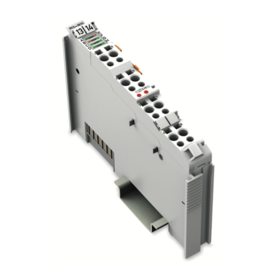
Page 7: Properties
3.1 View Figure 1: View Item number 8 Scope of Applicability [} 5] Marking possibility with Mini-WSB (op- tional) & System Manual I/O System 750/753 Data contacts 8 Indicators [} 8] Indicators 8 Diagnostics via Indicators [} 34] & System Manual I/O System 750/753 Access to open the associated CAGE ®... -
Page 8: Indicators
Properties 753-1631 3.2 Indicators A green status LED indicates the operating status and signals error-free local bus com- munication. Red error LEDs indicate the status of the field-side power supply and the presence of a general error. Other LEDs provide information on diagnostic states. Figure 2: Indicators Designation Local bus status... -
Page 9: Wiring Interface
753-1631 Properties 3.3 Wiring Interface Figure 3: Wiring Interface Designation Connection Function Digital input Digital output 24 V Field supply 24 VDC tap 0 V Field supply 0 V potential tap SMI communication cable I+ I− SMI communication cable I− Illustration including plug (not included) Product manual | Version: 3.0.0 SMI Master LoVo;... -
Page 10: Power Jumper Contacts
Properties 753-1631 3.4 Power Jumper Contacts The potential for the field supply is fed in via the blade contacts and passed on via the spring contacts. Figure 4: Power Jumper Contacts Type Groove with spring contact Groove without contact Blade contact Arrangement in the Bus Node For mechanical arrangement of the I/O module, the previous component must have at least 2 open grooves for accommodating the blade contacts. -
Page 11: Circuit Diagram
753-1631 Properties 3.5 Circuit Diagram Figure 5: Circuit Diagram & System Manual I/O System For information on the system power supply, please see 750/753. Product manual | Version: 3.0.0 SMI Master LoVo; 24 VDC... -
Page 12: Functions
In full mode, process data is communicated via the Mailbox 2.0 protocol, which is super- imposed on the process image. The WAGO SMI Configurator and IEC function blocks al- low other SMI functions to be used in addition to the functions available in fieldbus cou- pler mode. -
Page 13: Signal Processing
753-1631 Functions 4.2 Signal Processing 4.2.1 Fieldbus Coupler Mode 4.2.1.1 Digital Input The digital input offers the following functions: • 1-button mode • Trigger for safety position • No function in the SMI Master Module; evaluation of the digital input in the PLC The digital input corresponds to IEC 61131-2, Type 1. -
Page 14: 2-Button Mode
Functions 753-1631 After the forced position is triggered, the SMI Master Module does not pass any specific SMI commands or setpoints to the SMI LoVo Drives. The SMI LoVo Drives cannot be controlled again until the cause that triggered the motion to the forced position is elimi- nated. -
Page 15: Auto-Replace
The only way to restore the data is using the WAGO SMI Configu- rator or IEC function blocks. -
Page 16: Shutter And Slat Positioning
Functions 753-1631 As an alternative to automatic activation and deactivation, energy saving mode can also be manually activated and deactivated in the process data via extended control byte C1. The SMI master module switches to energy saving mode if the following events occur: •... -
Page 17: Full Mode
753-1631 Functions Figure 6: Schematic Representation of the Positioning of Shutters and Slats Position Description Setting ranges for positioning shutters and slats Positioning of slats in the event of upwards motions Positioning of slats in the event of downwards motions Positioning offset Setting range of slats (total angle of motion) Due to the shutter’s design, mechanical latency occurs between the initial motion of the SMI LoVo Drives and the initial reaction of the slats;... -
Page 18: System Expansion
4.2.2.4 Extended SMI Command Set Both the WAGO SMI Configurator and the IEC function block library allow you to use all the functions in accordance with the SMI specification, such as moving to absolute posi- tions of the SMI LoVo Drives and writing and reading drive parameters in the drives. -
Page 19: Process Image
Process data communication with the SMI master module takes place in fieldbus coupler mode via a cyclic process image and in full mode via the Mailbox 2.0 protocol. The WAGO SMI Configurator and the IEC function blocks also use register communica- tion. - Page 20 Functions 753-1631 Status Byte In the event of an error, the status byte represents only one other diagnostic besides the “General Error” diagnostic. If multiple errors are detected at the same time, the diagnostic with the highest priority is represented. Table 3: Status Byte S0 Bit 7 Bit 6...
-
Page 21: Table 4 Extended Control Byte C1
753-1631 Functions Extended Control Byte Table 4: Extended Control Byte C1 Bit 7 Bit 6 Bit 5 Bit 4 Bit 3 Bit 2 Bit 1 Bit 0 Controller Energy sav- Controller locking ing mode failure moni- toring Not used Controller locking Heartbeat of the PLC for controller failure monitoring Energy saving mode Energy saving mode:... -
Page 22: Local Bus Processing
Functions 753-1631 4.3.3 Local Bus Processing 4.3.3.1 Fieldbus Coupler Mode Process data is communicated via the cyclic process image. The SMI master module can be controlled without PLC programming via a fieldbus coupler. Use of the cyclic process image requires all SMI LoVo Drives to be addressed properly. Output and Input Process Images in Fieldbus Coupler Mode Table 6: Output and Input Process Images in Fieldbus Coupler Mode Byte... -
Page 23: Table 7 Commands
753-1631 Functions To perform the same control for multiple SMI LoVo Drives at the same time, enter the in- dividual value total for the drive addresses in word 3. For example, enter the value “0x8002,” “10000000_00000010” or “32770” (2^0x01 +2^0x0F) for the SMI LoVo Drives with drive addresses 0x01 and 0x15. -
Page 24: Table 8 Responses To Request Commands
Functions 753-1631 Command Code Designation Description 0x000C REQ_MOVE_UP_UNRPT The SMI Master Module sends a command to the SMI LoVo Drive to move all the way up. It is not re- peated if a transmission error oc- curs. 0x000D REQ_MOVE_DOWN_UNRPT The SMI Master Module sends a command to the SMI LoVo Drive to move all the way down. - Page 25 753-1631 Functions Command Code Designation Description 0x0011 RES_ERROR_START_WITH- The SMI Master Module expected OUT_STX the response “Data response SMI drive” but received an invalid re- sponse. 0x0012 RES_ERROR_TOO_SMALL_RE- The SMI Master Module received an SPONSE incomplete response. 0x0013 RES_ERROR_UNASSOCI- The SMI Master Module received a ATED_CMD response to an unrequested com- mand.
-
Page 26: Fieldbus Coupler Mode
Functions 753-1631 4.4 Diagnostic Functions 4.4.1 Local Bus Communication Fieldbus coupler mode offers the following monitoring functions: • Local bus failure monitoring • Controller failure monitoring • Power failure monitoring 8 Diagnostics via Indicators The effects of the displayed statuses are described in [} 34]. -
Page 27: Planning
Read system manual! You can find cross-product information on the topic of Planning in the & System Manual I/O System 750/753. 5.1 Structure Guidelines 5.1.1 Buffering To compensate for power interruptions per IEC 61131 (PS-1 or PS-2), external buffering is required. -
Page 28: Table 9 Compatibility List - Fieldbus Coupler Mode
Planning 753-1631 Table 9: Compatibility List – Fieldbus Coupler Mode Bussystem Head Station Item no. Version Firmware PROFINET Fieldbus coupler 750-370 750-375 750-377 PROFIBUS Fieldbus coupler 750-333 Controller 750-833 ETHERNET Fieldbus coupler 750-342 750-352 750-362 Controller 750-841 750-842 750-843 750-852 750-862... -
Page 29: Full Mode
In Full mode, the SMI master module is supported by the fieldbus couplers/controllers in the following table. Table 10: Compatibility List – Full Mode Bussystem Head Station Item no. Version Firmware ETHERNET Controller 750-852 750-880 750-881 750-882 750-885 PFC100 Controller 750-8100 750-8101 750-8102... -
Page 30: Aids
5.4.3 WAGO SMI Configurator You can use the WAGO SMI Configurator software to fully configure and commission the SMI Master Module via a graphical user interface and to commission SMI LoVo Drives. You can obtain the WAGO SMI Configurator software, as well as the associated product manual with a detailed description of the software, free of charge from ü www.wago.com. -
Page 31: Connection Examples
753-1631 Planning 5.5 Connection Examples Figure 7: 2-Wire Connection Example Figure 8: 2-Wire Connection for Energy Saving Mode Product manual | Version: 3.0.0 SMI Master LoVo; 24 VDC... -
Page 32: Commissioning
SMI line are set up correctly and are functioning properly. 6.1.1 Preparing and Carrying Out the Example Configuration In the example given here, the fieldbus node consists of the following WAGO I/O System components: Table 11: Example of a Fieldbus Node Setup Item no. -
Page 33: Diagnostics
7.1 Behavior of the I/O Module in the Event of an Error The behavior of the SMI master module if a diagnostic is present depends on the configu- ration. The diagnostics can be globally activated or deactivated in the WAGO SMI Config- urator and via IEC function blocks. -
Page 34: Diagnostics Via Indicators
Diagnostics 753-1631 7.3 Diagnostics via Indicators Table 13: Diagnostics via Indicators Designation LED State Explanation Local bus status Local bus failure moni- toring: Not ready for operation, or no/faulty local bus commu- nication • The error status is indi- cated in the status byte by setting the corre- sponding status bit. - Page 35 753-1631 Diagnostics Designation LED State Explanation RxD (data receipt) No SMI telegram is cur- rently being received. Green SMI telegram was just re- ceived. Digital output In Low state Green In High state The SMI Master Module automatically monitors the SMI LoVo Drives attached to its SMI interface in the background.
-
Page 36: Service
Enabled 8.2 Firmware Update/Downgrade You can update the firmware on the Series 750, 753 and 750 XTR I/O modules with the “WAGO IO-Update 750” software. The I/O module is updated via the service interface. For ETHERNET-based fieldbuses, the I/O module can also be updated via the fieldbus connection on the head station. -
Page 37: Application Example
753-1631 Service 8.3 Application Example 8.3.1 Use 1-Button Operating Mode CAUTION External button moves all SMI drives simultaneously By pressing the external button, all SMI drives connected to the SMI master module are addressed and moved simultaneously. An unprepared range of motion can lead to per- sonal injury/property damage. -
Page 38: Appendix
Appendix 9.1 Technical Data, Approvals, Duidelines and Standards Note Subject to changes! Please also observe the further product documentation! You can generate the current ü www.wago.com datasheet at any time at: /<item number>. See also 2 Data_sheet_753-1631 [} 39] Product manual | Version: 3.0.0... - Page 39 Communication between applications and SMI LoVo drives is performed via special IEC function blocks. These function blocks support both single and group addressing, as well as status monitoring. The SMI function blocks can be used with the 750 Series Programmable Fieldbus Controllers. Alternatively, the fieldbus coupler mode provides simple function calls for control without complex PLC programming.
- Page 40 TP TC 020/2011 EAC RU C-DE.AM02.B.00087/19 Brjansker Zertifizierungsstelle Article 58-2, Clause 3 MSIP-REM-W43-MCM750 National Radio Research Agency WAGO GmbH & Co. KG Postfach 2880 - D-32385 Minden Phone: +49(0)571/887-0 Email: info@wago.com 30.01.23 Subject to changes Hansastr. 27 - D-32423 Minden Fax: +49(0)571/887-844169 www.wago.com...
- Page 41 753-1631 List of Tables List of Tables Table 1 Behavior of SMI Drives and Shutters in the Event of Button Presses ....... Table 2 Control Byte C0........................Table 3 Status Byte S0 ........................Table 4 Extended Control Byte C1 ....................Table 5 Extended Status Byte S1 ....................
- Page 42 List of Figures 753-1631 List of Figures Figure 1 View ..........................Figure 2 Indicators ........................Figure 3 Wiring Interface ......................Figure 4 Power Jumper Contacts ....................Figure 5 Circuit Diagram ......................Figure 6 Schematic Representation of the Positioning of Shutters and Slats......Figure 7 2-Wire Connection Example ..................
- Page 43 753-1631 List of Figures Product manual | Version: 3.0.0 SMI Master LoVo; 24 VDC...
- Page 44 WAGO is a registered trademark of WAGO Verwaltungsgesellschaft mbH. Copyright – WAGO GmbH & Co. KG – All rights reserved. The content and structure of the WAGO websites, catalogs, videos and other WAGO media are subject to copyright. Distri- bution or modification of the contents of these pages and videos is prohibited. Furthermore, the content may neither be copied nor made available to third parties for commercial pur-...
Need help?
Do you have a question about the 750 and is the answer not in the manual?
Questions and answers