Table of Contents
Advertisement
Quick Links
Download this manual
See also:
Service Manual
Advertisement
Table of Contents

Related Manuals for Mindray BC-2800


Summary of Contents for Mindray BC-2800
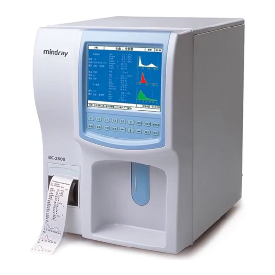
- Page 1 BC-2800 Auto Hematology Analyzer Operator’s Manual...
- Page 3 Contents of this manual are subject to change without prior notice. All information contained in this manual is believed to be correct. Mindray shall not be liable for errors contained herein or for incidental or consequential damages in connection with the furnishing, performance, or use of this manual.
- Page 4 It is important for the hospital or organization that employs this equipment to carry out a reasonable service/maintenance plan. Neglect of this may result in machine breakdown or personal injury. Be sure to operate the analyzer under the situation specified in this manual; otherwise, the analyzer will not work normally and the analysis results will be unreliable, which would damage the analyzer components and cause personal injury.
- Page 5 Exemptions Mindray's obligation or liability under this warranty does not include any transportation or other charges or liability for direct, indirect or consequential damages or delay resulting from the improper use or application of the product or the use of parts or accessories not approved by Mindray or repairs by people other than Mindray authorized personnel.
- Page 6 Return Policy Return Procedure In the event that it becomes necessary to return this product or part of this product to Mindray, the following procedure should be followed: Return authorization: Contact the international Customer Service Department and obtain a Return Materials Authorization number. This number must appear on the outside of the shipping container.
-
Page 7: Table Of Contents
Table of Contents Using This Manual ................... 1-1 Introduction .................... 1-1 Who Should Read This Manual ............. 1-2 How to Find Information................. 1-3 Conventions Used in This Manual ............1-4 Special Terms Used in This Manual............1-5 Symbols ....................1-6 Understanding Your Analyzer.............. - Page 8 Table of Contents 3.4.3 Derivation of WBC-Related Parameters ........3-6 3.4.4 HGB..................... 3-7 RBC/PLT Measurement ................. 3-8 3.5.1 Volumetric Metering ..............3-8 3.5.2 Measurement Principles.............. 3-9 3.5.3 Derivation of RBC-Related Parameters ........3-9 3.5.4 Derivation of PLT-Related Parameters ........3-11 Wash ....................
- Page 9 Table of Contents Power-on....................6-3 Daily Quality Control ................6-4 Selecting Analysis Mode ................ 6-5 Sample Collection and Handling............6-6 6.6.1 Whole Blood Samples..............6-6 6.6.2 Prediluted Samples ..............6-7 Running Whole Blood Samples ............. 6-9 6.7.1 Entering Sample Information ............6-9 6.7.2 Running the Samples..............
- Page 10 Table of Contents 9.3.4 Manual Calibration Program ............. 9-17 Maintaining Your Analyzer ..............10-1 10.1 Introduction ..................10-1 10.2 General Guidelines ................10-2 10.3 Using the “Maintenance” Program ............10-3 10.3.1 Diluent Prime................10-4 10.3.2 Rinse Prime................10-5 10.3.3 Lyse Prime ................10-6 10.3.4 Zap Aperture ................
- Page 11 Table of Contents Precautions, Limitations and Hazards ...........C-1 Communication (8ID communication protocol) ........D-1 Communication (15ID communication protocol) ........E-1...
-
Page 13: Using This Manual
1.1 Introduction This chapter explains how to use your operator’s manual, which is shipped with your BC-2800 auto hematology analyzer and contains reference information about the BC-2800 and procedures for operating, troubleshooting and maintaining the analyzer. Read this manual carefully before operating your analyzer and operate your analyzer strictly as instructed in this manual. -
Page 14: Who Should Read This Manual
Using This Manual 1.2 Who Should Read This Manual This manual contains information written for clinical laboratory professionals to learn about the BC-2800 hardware and software; customize system settings; perform daily operating tasks; perform system maintenance and troubleshooting. -
Page 15: How To Find Information
Analyzer learn about how to define/adjust system settings Chapter 5 Customizing the Analyzer Software learn about how to use the BC-2800 to perform your daily Chapter 6 Operating Your operating tasks Analyzer learn about how to review the saved analysis results... -
Page 16: Conventions Used In This Manual
Using This Manual 1.4 Conventions Used in This Manual This manual uses certain typographical conventions to clarify meaning in the text: All capital letters enclosed in [ ] indicate a key name (either on the built-in keypad or the external keyboard), such as [ENTER]. All capital, bold and italic letters indicate a special operation defined in the following section, such as SELECT. -
Page 17: Special Terms Used In This Manual
Using This Manual 1.5 Special Terms Used in This Manual When you read … It means … to press the arrow keys ([←][→] [↑][↓]) as needed to move the CLICK cursor to a certain software button on screen and press [ENTER]. -
Page 18: Symbols
Using This Manual 1.6 Symbols You will find the following symbols in this manual. When you see… Then… read the statement below the symbol. The statement is alerting you to an operating hazard that can cause personnel injury. read the statement below the symbol. The statement is alerting you to a possibility of analyzer damage or unreliable analysis results. - Page 19 Using This Manual SERIAL NUMBER IN VITRO DIAGNOSTIC DATE OF MANUFACTURE TEMPERATURE LIMITATION CONSULT INSTRUCTIONS FOR USE THE DEVICE IS FULLY CONFORMANCE WITH COUNCIL DIRECTIVE CONCERNING IN VITRO DIAGNOSTIC MEDICAL DEVICES 98/79/EC. MANUFACTURER AUTHORISED REPRESENTATIVE IN THE EUROPEAN COMMUNITY IRRITATING SUBSTANCE THE FOLLOWING DEFINITION OF THE WEEE LABEL APPLIES TO EU MEMBER STATES ONLY: THE USE OF THIS SYMBOL...
- Page 20 Using This Manual RETURNING RECYCLING THIS PRODUCT, PLEASE CONSULT DISTRIBUTOR FROM WHOM PURCHASED THE PRODUCT.
- Page 21 Using This Manual (4) (3) (2) (1) Figure 1-1 Back of the analyzer Equipotentiality. (2) Connect only to a properly earth grounded outlet; To avoid electric shock, disconnect power cord prior to removing or replacing fuse; Replace fuse only with the type and rating specified. (3)...
- Page 22 Using This Manual this product is disposed of correctly, you will help prevent bringing potential negative consequences to the environment and human health. For more detailed information with regard to returning and recycling this product, please consult the distributor from whom you purchased the product.
- Page 23 Using This Manual (6) Figure 1-3 Warning label (6) To avoid electrical shock, disconnect the power supply before maintaining this device. 1-11...
- Page 24 Using This Manual (7) Figure 1-4 High voltage warning label (7) High Voltage 1-12...
-
Page 25: Understanding Your Analyzer
Understanding Your Analyzer 2.1 Introduction The BC-2800 Auto Hematology Analyzer is a quantitative, automated hematology analyzer and leukocyte differential counter for In Vitro Diagnostic Use in clinical laboratories. -
Page 26: Intended Use
Understanding Your Analyzer 2.2 Intended Use The purpose of this analyzer is to identify the normal patient, with all normal system-generated parameters, and to flag or identify patient results that require additional studies. The analyzer is used for the quantitative determination of a maximum of 19 parameters and 3 histograms of blood samples. -
Page 27: User Interface
Understanding Your Analyzer 2.3 User Interface Figure 2-1 Front view 1 ---- LCD 2 ---- Keypad 3 ---- Recorder 4 ---- Power indicator 5 ---- Aspirate key 6 ---- Sample probe... - Page 28 Understanding Your Analyzer Figure 2-2 Back view 1 --- Power switch 2 --- Equipotentiality 3 --- Waste outlet(Red) 4 --- Lyse inlet(Orange) 5 --- Rinse inlet(Blue) 6 --- Diluent inlet(Green)
- Page 29 Understanding Your Analyzer Figure 2-3 Left view 1 --- RS-232 port1 2 --- Parallel port 3 --- RS-232 port2 4 --- Power Interface of Floppy Disk Drive 5 --- Keyboard interface...
-
Page 30: Lcd
Understanding Your Analyzer 2.3.1 LCD The LCD is located on the front panel of the analyzer, as Figure 2-4 shows. It displays all alphanumeric and graphic data. 2.3.2 Input Devices The input devices include the aspirate key, built-in keypad and PS/2 keyboard. Aspirate key The aspirate key is located behind the sample probe, as Figure 2-4 shows. - Page 31 Understanding Your Analyzer Built-in keypad The 18-key keypad is located below the LCD, as Figure 2-5 shows. Figure 2-5 Build-in keypad PS/2 keyboard The analyzer can also be controlled by an external PS/2 keyboard that should be connected to the analyzer’s keyboard interface. See Table 2-1 for the correspondence between the keypad keys and the keyboard keys and for their functions.
-
Page 32: Recorder
The analyzer provides a parallel port to connect a printer or a floppy disk drive (a floppy disk drive is needed to upgrade the system software; the drive can only be connected by a Mindray-supplied cable). 2.3.7 Power Supply for the Floppy Disk Drive It supplies power to the connected floppy disk drive. -
Page 33: Instrument Software
Understanding Your Analyzer 2.4 Instrument Software 2.4.1 Main Screen After finishing the startup procedure, the analyzer enters the “Count” screen, which is the screen to be used most frequently, hence the name is main screen. Title Area Count Mode Area System Status Area Error Message Help Area... -
Page 34: Screen Saver
Understanding Your Analyzer The System Time area displays the system time. Sample Information Area The Sample Information area has two sub-areas, the upper titled “Current sample” and the lower “Next sample”. The “Current sample” refers to the sample, whose analysis result is displayed on the “Count”... -
Page 35: System Menu
Understanding Your Analyzer 2.4.3 System Menu Press the [MENU] button and the system menu, shown in Figure 2-7 below, will pop up. Figure 2-7 System menu The system menu contains 7 programs. The programs followed by “>”s have further sub-menus. See Figure 2-8 for the expanded menu. Figure 2-8 Fully expanded system menu 2-11... - Page 36 Understanding Your Analyzer You can select the desired program as instructed below. If you want to… Select… analyze samples Count review sample results Review run the QC program Quality Control customize system software Setup maintain/service the analyzer Service calibrate the analyzer Calibration shut down the analyzer Shutdown...
-
Page 37: Reagents, Controls And Calibrator
You should only use the Mindray-specified reagents (see Appendix B Specifications), which are formulated specifically for the fluidic system of your analyzer in order to provide optimal system performance. -
Page 38: Rinse
Read and follow the instructions for use to use the controls and calibrators. All references related to controls and calibrators in this manual refer to the controls and calibrators reagents specifically formulated for this analyzer. Controls and calibrators can be purchased from Mindray or Mindray-authorized distributors. 2-14... -
Page 39: Understanding The System Principles
Understanding the System Principles 3.1 Introduction The two independent measurement methods used in this analyzer are: the impedance method for determining the WBC, RBC, and PLT data; the colorimetric method for determining the HGB. During each analysis cycle, the sample is aspirated, diluted and mixed before the determination for each parameter is performed. -
Page 40: Aspiration
Understanding the System Principles 3.2 Aspiration This analyzer can process two types of blood samples – whole blood samples and prediluted blood samples. If you are going to analyze a whole blood sample, you can simply present the sample to the sample probe and press the aspirate key to aspirate 13µL of the sample into the analyzer. -
Page 41: Dilution
Understanding the System Principles 3.3 Dilution Usually in blood samples, the cells are too close to each other to be identified or counted. For this reason, the diluent is used to separate the cells so that they are drawn through the aperture one at a time as well as to create a conductive environment for cell counting. -
Page 42: Wbc/Hgb Measurement
Understanding the System Principles 3.4 WBC/HGB Measurement 3.4.1 Volumetric Metering An accurate cell count cannot be obtained unless the precise volume of diluted sample that passes through the aperture during the count portion of the analysis cycle (the count cycle) is known. -
Page 43: Measurement Principles
Understanding the System Principles 3.4.2 Measurement Principles WBC measurement WBCs are counted and sized by the impedance method, as Figure 3-2 shows. This method is based on the measurement of changes in electrical resistance produced by a particle, which in this case is a blood cell, suspended in a conductive diluent as it passes through an aperture of known dimensions. -
Page 44: Derivation Of Wbc-Related Parameters
Understanding the System Principles HGB(g/L) = Constant×Log (Blank Photocurrent/Sample Photocurrent) 3.4.3 Derivation of WBC-Related Parameters WBC (10 / L) is the number of leukocytes measured directly by counting the white blood cells passing through the aperture. × Note that NRBCs do not react with the lyse and can be mistaken by the analyzer for white blood cells. -
Page 45: Hgb
Understanding the System Principles × Lymph Lymph × × Gran Gran WBC histogram Besides the parameters mentioned above, this analyzer also presents a WBC histogram, whose x-coordinate represents the cell volume(fL)and y-coordinate represents the number of the cells. The histogram is presented in the Analysis Result area of the “Count” screen when the analysis is done. -
Page 46: Rbc/Plt Measurement
Understanding the System Principles 3.5 RBC/PLT Measurement 3.5.1 Volumetric Metering An accurate cell count cannot be obtained unless the precise volume of diluted sample that passes through the aperture during the count cycle is known. This analyzer uses a volumetric metering unit to control the count cycle and to ensure that a precise volume of sample is analyzed for the measurement. -
Page 47: Measurement Principles
Understanding the System Principles 3.5.2 Measurement Principles RBC/PLT measurement RBCs/PLTs are counted and sized by the impedance method, as Figure 3-4 shows. This method is based on the measurement of changes in electrical resistance produced by a particle, which in this case is a blood cell, suspended in a conductive diluent as it passes through an aperture of known dimensions. - Page 48 Understanding the System Principles expresses the result in fL. This analyzer calculates the HCT (%), MCH (pg) and MCHC (g/L) as follows: × MCH = × MCHC Where the RBC is expressed in 10 /L, MCV in fL and HGB in g/L. RDW-CV Based on the RBC histogram, this analyzer calculates the CV (Coefficient of Variation) of the erythrocyte distribution width.
-
Page 49: Derivation Of Plt-Related Parameters
Understanding the System Principles 3.5.4 Derivation of PLT-Related Parameters PLT (10 /L) is measured directly by counting the platelets passing through the aperture. Based on the PLT histogram, this analyzer calculates the mean platelet volume (MPV, fL). Platelet distribution width (PDW) is the geometric standard deviation (GSD) of the platelet size distribution. -
Page 50: Wash
Understanding the System Principles 3.6 Wash After each analysis cycle, each element of the analyzer is washed. The sample probe is washed internally and externally with diluent; The bath is washed with diluent and rinse; The metering tube is washed with rinse; The rest of the fluidic system is washed by diluent. -
Page 51: Installing Your Analyzer
Installing Your Analyzer 4.1 Introduction This chapter introduces how to install the BC-2800. To ensure all system components function correctly and to verify system performance, Mindray-authorized representatives will handle the installation and initial software setup. Installation by personnel not authorized or trained by Mindray may damage your analyzer. -
Page 52: Installation Requirements
Installing Your Analyzer 4.2 Installation Requirements Before installation, you should ensure that the following space, power and environmental requirements are met. 4.2.1 Space Requirements Check the site for proper space allocation. In addition to the space required for the analyzer itself, arrange for at least 28 cm on each side, which is the preferred access to perform service procedures;... -
Page 53: General Environment
Installing Your Analyzer 4.2.3 General Environment Operating temperature: 15 ℃ to 30 ℃. Relative humidity: 30% to 85%. Atmospheric pressure: 60 kPa to 106 kPa. The environment should be as free as possible from dust, mechanical vibrations, loud noises, and electrical interference. Do not place the analyzer near brush-type motors, flickering fluorescent lights, and electrical contacts that regularly open and close. -
Page 54: Unpacking
If you see any signs of mishandling or damage, contact Mindray customer service department or your local distributor immediately. When you are sure the carton is fine, follow the steps below to unpack the analyzer: Place the carton on the floor upright with the arrows on the side upwards;... -
Page 55: Installation Procedure
Installing Your Analyzer 4.4 Installation Procedure Dispose of reagents, waste, samples, consumables, etc. according to government regulations. The reagents are irritating to eyes, skin and diaphragm. Wear proper personal protective equipment (e.g. gloves, lab coat, etc.) and follow safe laboratory procedures when handling them in the laboratory. If the reagents accidentally spill on your skin, wash them off with plenty of water and if necessary, go see a doctor;... - Page 56 Installing Your Analyzer (Figure 4-1); Figure 4-1 Diluent container 2. Take out the diluent container and place it on or below the countertop; 3. Remove the container cap and insert the tube end that has no connector into the diluent container and tighten the cap until properly secured, as Figure 4-2 shows;...
- Page 57 Installing Your Analyzer Figure 4-3 Rinse container 2. Take out the rinse container and place it on or below the countertop; 3. Remove the container cap and insert the tube end that has no connector into the rinse container and tighten the cap until properly secured, as Figure 4-4 shows; Figure 4-4 Insert the tube end into the container 4.
- Page 58 Installing Your Analyzer Figure 4-5 Lyse container 2. Take out the lyse container; 3. Remove the container cap and insert the tube end that has no connector into the container and tighten the cap until properly secured, as Figure 4-6 shows; Figure 4-6 Insert the tube into the container 4.
-
Page 59: Installing Recorder Paper
Installing Your Analyzer 4.4.2 Installing Recorder Paper Remove the protective paper between the recorder head and the roller inside the recorder before installing recorder paper. Follow the procedure below to install the recorder paper. Use the latch at the upper right corner of the recorder door to pull the door open. Insert a new roll into the compartment as shown below. -
Page 60: Connecting The Keyboard
Installing Your Analyzer 4.4.3 Connecting the Keyboard Take out the keyboard from the accessory kit and connect it to the keyboard interface marked “KB”. 4.4.4 Connecting the Printer (Optional) Follow the printer’s instructions for use to connect the printer to the parallel port. 4.4.5 Connecting the Bar-Code Scanner (Optional) Follow the scanner’s instructions for use to connect the scanner to the serial port1. -
Page 61: Starting The Analyzer
Installing Your Analyzer 4.5 Starting the Analyzer Take out the power cord from the accessory box. Plug the non-pronged end into the AC input at the back of the analyzer and the pronged end into an electrical outlet. Place the power switch at the back of the analyzer in the ON position (1) to turn on the analyzer. -
Page 63: Customizing The Analyzer Software
Customizing the Analyzer Software 5.1 Introduction The BC-2800 is a flexible laboratory instrument that can be tailored to your work environment. You can use the “Setup” program to customize the software options as introduced in Chapters 5.2 to 5.3. -
Page 64: Password
Customizing the Analyzer Software 5.2 Password The BC-2800 classifies users into two categories: common users (default) and administrators. You need to enter the administrator password to adjust certain options such as “Count”, “Gain”, etc. 5.2.1 Entering the Administrator Password Press [MENU] to enter the system menu. -
Page 65: Resuming The Common User Password
Customizing the Analyzer Software Figure 5-3 A message box to confirm the user level CLICK “Yes” to confirm the password and exit to the system menu. 5.2.2 Resuming the Common User Password Enter the “Password” screen and the default password is the common user password. Press [MENU] again and a message box will pop up to remind you of the current password level, as Figure 5-4 shows. -
Page 66: Editing Settings
Customizing the Analyzer Software 5.3 Editing Settings You can use the “Settings” menu to edit system settings. Press [MENU] to enter the system menu. SELECT “Setup → Settings“, as Figure 5-5 shows, to enter the “Settings” screen, as Figure 5-6 shows. Figure 5-5 System menu Figure 5-6 “Settings”... -
Page 67: Reagent
Customizing the Analyzer Software This area displays useful information to help you move to the next step. At this screen, if you want to acquire help information, press [HELP]; if you want to return to the system menu, press [MENU]. 5.3.1 Reagent You can select the “Reagent”... -
Page 68: Printing And Communication Settings
Customizing the Analyzer Software 1. SELECT “Waste Container”; 2. ENTER the desired digits. Entering expiration dates of reagents You can specify the expiration dates for the diluent, rinse and lyse. Once any of these reagents is expired, the system will alert you to install a new container. Follow the steps given below to enter the expiration dates. - Page 69 Customizing the Analyzer Software to your own need, as Figure 5-10 shows. Figure 5-10 Printing and communication settings Selecting the “Print & comm.” group Press [F1] to select the “Print & comm.” group. Selecting the printing device To select a printing device, SELECT “Recorder” or “Printer” from the “Device” drop-down list, as Figure 5-10 shows.
- Page 70 Customizing the Analyzer Software Figure 5-11 Selecting printing format Auto printing The auto printing function refers to the analyzer’s ability to automatically print out the analysis results once they are done. To activate this function, SELECT “ON” (or “OFF”) from the “Auto”...
- Page 71 Customizing the Analyzer Software Figure 5-13 Selecting baud rate Selecting parity To choose the “Odd”, “Even” or “None” (default) check, SELECT the desired check from the “Parity” drop-down list, as Figure 5-14 shows. Figure 5-14 Setting parity Activating/deactivating handshake If the “Handshake” function is activated, to start the transmission this analyzer will send a handshake signal to an external computer and wait for the response.
- Page 72 Customizing the Analyzer Software To activate or deactivate this option, SELECT “Yes” or ”No” from the “Handshake” drop-down list, as Figure 5-15 shows. Figure 5-15 Setting handshake Auto Communication The auto communication function refers to the analyzer’s ability to automatically transmit the analysis results to an external computer once they are done.
-
Page 73: Date And Time
Customizing the Analyzer Software printing device; 2. ENTER the desired report title. Exiting the “Print & comm.” group When you have finished changing all the desired printing and transmission settings, you may press [F1] to select another setting group you want to change; or press [MENU] and a message box will pop up to remind you to save the changes, as Figure 5-17 shows. - Page 74 Customizing the Analyzer Software Selecting the date format You may choose one of the three formats “YYYY-MM-DD”, “MM-DD-YYYY“ and “DD-MM-YYYY”. To do so, SELECT the desired format from the “Format” drop-down list, as Figure 5-19 shows. Figure 5-19 Setting date format Setting the system time 1.
-
Page 75: Gain
Customizing the Analyzer Software 5.3.4 Gain You can select the “Gain” group to view or change (if you have the administrator password) the WBC, RBC and HGB gains. Figure 5-21 Setting gain Selecting the “Gain” group Press [F1] to select the “Gain” group, as Figure 5-21 shows. Setting the WBC gain When WBC histograms of most samples are similar to Figure 5-22, it implies too small a WBC gain and you need to increase the gain appropriately. - Page 76 Customizing the Analyzer Software To increase (or decrease) the gain 1. Enter the administrator password as introduced in Chapter 5.2.1. 2. At the ”Gain” screen and ENTER the desired gain into the “WBC (WB) ”, as Figure 5-24 shows, or “WBC (PB)”, as Figure 5-25 shows. Figure 5-24 Setting WBC (WB) gain Figure 5-25 Setting WBC (PB) gain Setting the RBC gain...
- Page 77 Customizing the Analyzer Software For example, assuming the expected MCV result is 90.0fL, while the actual analysis result is 82.0fL, then ExpectedMC × × = ActualMCV You should adjust the RBC gain to 109.8% as close as possible. Follow the steps given below to do so.
-
Page 78: Count
Customizing the Analyzer Software Figure 5-27 Setting HGB gain Exiting “Gain” group When you have finished changing all the desired gain settings, you may 1. Press [F1] to select another setting group you want to change; or; 2. Press [MENU] and a message box will pop up to remind you to save the changes, as Figure 5-28 shows. - Page 79 Customizing the Analyzer Software Figure 5-29 Setting unit and count time Selecting the “Count” group Press [F1] to select the “Count” group, as Figure 5-29 shows. Selecting parameter units This analyzer provides multiple units for certain parameters. Refer to Table 5-2 for all the selectable units of all parameters.
- Page 80 Customizing the Analyzer Software *.** Default *.** *.** **.* Default .*** MCV, RDW-SD ***.* Default ***.* RDW-CV **.* Default **** Default **** ***.* **** ***.* Default ***.* **.* Default .*** Default *.** mL/L *.*** Default **.** fmol Follow the steps given below to select the units. 1.
- Page 81 Customizing the Analyzer Software Figure 5-30 Selecting parameter unit Setting count time If the WBC or RBC count time is inappropriately set, the system may give false alarms for clogs or bubbles. When this happens, follow the steps given below to change the WBC or RBC count time.
-
Page 82: Reference Range
Customizing the Analyzer Software When you have finished changing all the parameter units and count time settings you want to change, you may 1. Press [F1] to select another setting group you want to change; or; 2. Press [MENU] and a message box will pop up to remind you to save the changes, as Figure 5-32 shows. - Page 83 Customizing the Analyzer Software only to administrators, as Figure 5-33 shows. Follow the instructions below to set the ranges. Figure 5-33 Reference range screen Selecting patient group Follow the steps given below to select the patient group you want. 1. At the “Settings” screen, press [F1] to select the “Ref. Range” group. 2.
- Page 84 Customizing the Analyzer Software Setting reference ranges (administrators only) 1. Enter the administrator password as introduced in Chapter 5.2.1; 2. At the “Settings” screen, press [F1] to select the “Ref. Range” group, as Figure 5-35 shows; 3. When you have finished selecting the patient group, SELECT the desired parameter and ENTER the desired digits for the upper and lower limits;...
-
Page 85: Auto Maintain
Customizing the Analyzer Software Figure 5-37 A message box to remind you of the erroneous entry 6. If you want to resume the default settings, press [F4]. Exiting the “Ref. Range” group When you have finished changing all the parameter units and count time settings you want to change, you may 1. - Page 86 Customizing the Analyzer Software 3) how many WB samples had been run after probe wipe cleaning. For more information about auto maintain, see Chapter 10 Maintaining Your Analyzer for detail. Change the WB samples can be run between two cleanings 1.
-
Page 87: Other Settings
Customizing the Analyzer Software 5.3.8 Other Settings You can select the “Other” group to view or change other settings. Selecting the “Other” group Press [F1] to select the “Other” group. Muting beeper This analyzer beeps when an error occurs. You can mute the beeper by pressing any key or leave it beeping until the errors are removed. - Page 88 Customizing the Analyzer Software Figure 5-42 Select LCD contrast Setting alarm time Follow the steps given below to set for how long (2s to120s) the error messages listed in Table 5-4 should be displayed on the screen. Table 5-4 Error List Error Error Error...
- Page 89 Customizing the Analyzer Software Figure 5-43 Setting alarm time Selecting PMB color (administrator password needed) The PMB color refers to the background color of the screen when your analyzer is in the prediluted mode. Follow the steps below to select the PMB color. 1.
- Page 90 Customizing the Analyzer Software in the edit window when input patient information. 1. Enter the administrator password as introduced in Chapter 5.2.1; 2. At the “Settings” screen, press [F1] to select the “Other” group; 3. SELECT “Not Delete” (default) or “Delete All” from the “Info. In list of Dept., Sender etc.”...
- Page 91 Customizing the Analyzer Software Figure 5-46 Saving changes 5-29...
-
Page 93: Operating Your Analyzer
Operating Your Analyzer 6.1 Introduction This chapter provides step-by-step procedures for operating your analyzer on a daily basis. Initial Checks Power on Daily Quality Control Sample Collection and Handling Whole Blood Mode? Run Prediluted Samples Run Whole Blood Samples Shutdown... -
Page 94: Initial Checks
Operating Your Analyzer 6.2 Initial Checks Perform the following checks before turning on the analyzer. 1. Check and make sure the waste container is empty; 2. Check and make sure there are enough reagents; Samples, controls, calibrator and waste are potentially infectious. Wear proper personal protective equipment (e.g. -
Page 95: Power-On
Operating Your Analyzer 6.3 Power-on Place the power switch at the back of the analyzer in the ON position (1) to turn on the analyzer. The power indicator light will be illuminated and the screen will display “Initializing…“. The analyzer will sequentially initialize the file, hardware and fluidic systems and the whole initializing process lasts 4 to 7 minutes, depending on how the analyzer was previously shut down. -
Page 96: Daily Quality Control
Operating Your Analyzer 6.4 Daily Quality Control Before running any samples, run the controls. See Chapter 8 Using the QC Programs for details. -
Page 97: Selecting Analysis Mode
Operating Your Analyzer 6.5 Selecting Analysis Mode At the “Count” screen, press [MODE] to select one of the six analysis modes. The selected mode will be displayed in the Count Mode area. 1. Whole - All It means the sample to be analyzed is a whole blood sample and all the 19 parameters are to be analyzed. -
Page 98: Sample Collection And Handling
Operating Your Analyzer 6.6 Sample Collection and Handling Samples, controls, calibrator and waste are potentially infectious. Wear proper personal protective equipment (e.g. gloves, lab coat, etc.) and follow safe laboratory procedures when handling them in the laboratory. Avoid direct contact with blood samples. Do not re-use disposable products. -
Page 99: Prediluted Samples
Operating Your Analyzer refrigerated samples at room temperature for at least 30 minutes before running them. Mix any sample that has been prepared for a while before running it. 6.6.2 Prediluted Samples Collect and handle the prediluted sample as follows: 1. - Page 100 Operating Your Analyzer Keep dust from the prepared diluent. When preparing a prediluted sample, only use lint-free tissue to wipe the external wall of the capillary tube; do not use cotton balls. After mixing the capillary sample with the diluent, wait 5 minutes before running the sample.
-
Page 101: Running Whole Blood Samples
Operating Your Analyzer 6.7 Running Whole Blood Samples Press [MENU] and SELECT ”Count” to enter the ”Count” screen, as Figure 6-3 shows. Figure 6-3 “Count” screen Press [MODE] to select whole blood mode (any mode preceded by Whole blood); Select proper reference range as instructed in Chapter 5.3.6 before running the samples. - Page 102 Operating Your Analyzer At the “Count” screen, use the bar-code scanner (if available) to scan the sample ID into the analyzer; or At the “Count” screen, press [F1] to enter the “ID” window and ENTER the sample ID. Figure 6-4 “Next sample” window When you have finished entering the sample ID, you may press [MENU] and a dialog box will pop up, as Figure 6-5 shows.
- Page 103 Operating Your Analyzer If you intend to do the background check instead of a patient sample, enter “0” into the “ID” box. All info mode (external keyboard needed) Entering Edit At the “Count” screen, press [F1] and an edit window will pop up, as Figure 6-6 shows. Figure 6-6 Entering sample information Entering sample ID ENTER the ID number in the “ID”...
- Page 104 Operating Your Analyzer Figure 6-7 How to select the patient gender Entering the patient name ENTER the patient name into the “Name” box. Entering the patient age This analyzer provides three ways for you to enter the patient age –in years, in months and in days.
- Page 105 Operating Your Analyzer Figure 6-8 Select department name Entering the names of the sender, tester and checker To enter the name of the person who sent the sample for analysis, enter the name into the “Sender” box or SELECT the desired name from the “Sender” pull-down list (if there are previously saved names in the list ) ;...
- Page 106 Operating Your Analyzer Figure 6-9 Batch edit screen Save CLICK “Save” to save the changes. Next/Prev If you want to review the entered information of a specific sample, press the appropriate arrow keys to CLICK “Prev.” or “Next” to review the previous or next sample until the desired sample is reached.
-
Page 107: Running The Samples
Operating Your Analyzer 6.7.2 Running the Samples Samples, controls, calibrator and waste are potentially infectious. Wear proper personal protective equipment (e.g. gloves, lab coat, etc.) and follow safe laboratory procedures when handling them in the laboratory. The sample probe tip is sharp and may contain biohazardous materials. Exercise caution to avoid contact with the probe when working around it. -
Page 108: Special Functions
Operating Your Analyzer area and the results of all the related parameters will be invalidated. See Chapter 11 Troubleshooting Your Analyzer for solutions. If the ambient temperature is outside the specified operating range, the analyzer will alarm you for abnormal ambient temperature and the analysis results may be unreliable. - Page 109 Operating Your Analyzer Figure 6-11 “Re-count” screen Follow the previously introduced procedure to re-analyze the sample in question. The new result will overwrite the old result while the sample information keeps unchanged. Automatic saving of analysis results This analyzer automatically saves a maximum of 10,000 sample results. When the maximum number has been reached, the newest result will overwrite the oldest.
- Page 110 Operating Your Analyzer platelet clumps, giant platelets, nucleated red cell, insolvable red cell, protein and lipoid debris in sample, or electrical noise. : indicates abnormality between the lymphocyte hump and the mid-sized cell area and possible presence of abnormal lymphocyte, plasma cell, atypical lymphocyte, original granulocytes in the sample and eosinophilia or basophilia.
-
Page 111: Running Prediluted Samples
Operating Your Analyzer 6.8 Running Prediluted Samples Press [MENU] and SELECT ”Count” to enter the ”Count” screen, as Figure 6-12 shows. Figure 6-12 “Count” screen in prediluted mode Press [MODE] to select prediluted mode (any mode preceded by Prediluted). Select proper reference range as instructed in Chapter 5.3.6 before running the samples. - Page 112 Operating Your Analyzer Figure 6-13 Entering ID of the next sample When you have finished entering the sample ID, you may press [MENU] and a dialog box will pop up, as Figure 6-14 shows. To ignore the entered number, CLICK “No”; otherwise, CLICK “Yes”.
- Page 113 Operating Your Analyzer All info mode (external keyboard needed) Entering Edit At the “Count” screen, press [F1] and an edit window will pop up, as Figure 6-15 shows. Figure 6-15 Entering sample information Entering sample ID ENTER the ID number in the “ID” box, or if you have the bar-code scanner installed, you can simply scan the sample ID into the analyzer.
- Page 114 Operating Your Analyzer Figure 6-16 How to select the patient gender Entering the patient name ENTER the patient name into the “Name” box. Entering the patient age This analyzer provides three ways for you to enter the patient age –in years, in months and in days.
- Page 115 Operating Your Analyzer Figure 6-17 Select department name Entering the names of the sender, tester and checker To enter the name of the person who sent the sample for analysis, enter the name into the “Sender” box or SELECT the desired name from the “Sender” pull-down list (if there are previously saved names in the list ) ;...
-
Page 116: Running The Samples
Operating Your Analyzer Figure 6-18 Batch edit screen Save CLICK “Save” to save the changes. Next/Prev If you want to review the entered information of a specific sample, press the appropriate arrow keys to CLICK “Prev.” or “Next” to review the previous or next sample until the desired sample is reached. -
Page 117: Special Functions
Operating Your Analyzer The sample probe tip is sharp and may contain biohazardous materials. Exercise caution to avoid contact with the probe when working around it. Do not re-use such disposable product as collection tubes, test tubes, capillary tubes, etc. Keep the sample probe tip away from the tube bottom, otherwise the aspiration volume may be inaccurate. - Page 118 Operating Your Analyzer If you don’t want to re-count this sample, CLICK “No”; otherwise, CLICK “Yes” to enter the “Re-count” screen. This “Re-count” screen is similar to the “Count” screen, except the lower sub-area of the Sample Information area is tiled “Re-count” as opposed to “Next sample”. The sample ID remains unchanged.
- Page 119 Operating Your Analyzer : indicates blur demarcation between the platelet and red blood cell area and possible presence of large platelet, platelet coagulation, small red blood cell, cell debris or fibrin. : indicates excessive small PLTs. : indicates excessive large PLTs. When the PLT value is less than 100 ×...
-
Page 120: Shutdown
Operating Your Analyzer 6.9 Shutdown Perform the “Shutdown” procedure to shut down the analyzer daily. To ensure stable analyzer performance and accurate analysis results, perform the “Shutdown” procedure to shut down the analyzer after it has been running continuously for 24 hours. Shut down the analyzer strictly as instructed below. - Page 121 Operating Your Analyzer Figure 6-22 Shutdown window The sample probe tip is sharp and may contain biohazardous materials. Exercise caution to avoid contact with the probe when working around it. The reagents are irritating to eyes, skin and diaphragm. Wear proper personal protective equipment (e.g.
- Page 122 Operating Your Analyzer Dispose of reagents, waste, samples, consumables, etc. according to government regulations. 6-30...
-
Page 123: Reviewing Sample Results
Reviewing Sample Results 7.1 Introduction The analyzer automatically saves analysis results. Totally 10,000 results can be saved. You can either browse all the saved sample results in general or search for the results of a particular sample or samples. -
Page 124: Browsing All Sample Results
Reviewing Sample Results 7.2 Browsing All Sample Results To browse all the saved sample results, you can choose either of the following modes: The ”Histogram” mode. In this mode, you can review both parameter values and histograms of the saved sample results, one sample result per screen. - Page 125 Reviewing Sample Results Browsing sample results Press [←] or [→] to browse the preceding or following sample result; press [PgUp] or [PgDn] to jump 8 locations (e.g. from location 1 to location 9). Switching to the “Table” mode To switch to the “Table” mode, press[↓]; to switch back to the “Histogram” mode, press[↓]again.
- Page 126 Reviewing Sample Results Figure 7-4 Editing sample information You cannot edit the sample ID of an analyzed sample. Selecting gender SELECT the desired item from the “Gender” drop-down list. Note that you can select blank in case you are not aware of the patient gender. Entering patient name ENTER the patient name into the “Name”...
- Page 127 Reviewing Sample Results Entering the bed number ENTER the number of the patient’s bed into the ”Bed No.“ box . Entering the department name You can either directly ENTER the name of the department, from which the sample came, into the “Dept” box or SELECT the desired department from the “Dept” pull-down list (if there are previously saved departments in the list).
- Page 128 Reviewing Sample Results 1. Press [ENTER] and the discriminator will become adjustable. See Figure 7-5; Figure 7-5 WBC histogram with adjustable discriminators 2. Press [↑] or [↓] as needed to select the WBC histogram, as Figure 7-6 shows; Figure 7-6 Adjusting discriminator (1) 3.
-
Page 129: Browsing In The "Table" Mode
Reviewing Sample Results Figure 7-8 Adjusting discriminator (3) 5. Press [ENTER] and a message box will pop up, as Figure 7-9 shows. Figure 7-9 Saving changes 6. CLICK “Yes” to save the changes and return to the “Review” screen. Printing sample results Press [PRINT] to print out the current sample result. - Page 130 Reviewing Sample Results lower right corner of the screen indicates the location of the current sample result (the one whose “ID” is backlit) and the total number of the sample results. Browsing sample results Press [←] or [→] to browse the preceding or following sample result; press [PgUp] or [PgDn] to browse the preceding or following screen.
- Page 131 Reviewing Sample Results Figure 7-12 Selecting a sample result Press [ENTER] again to deselect the sample result. Once the sample is deselected, the “*” will disappear, as Figure 7-13 shows. Figure 7-13 Deselecting a sample result Selecting/deselecting multiple sample results Example1: To select the sample results of locations 1 to 5 (sample IDs:114 to 118 ), follow the procedure below to do so: 1.
- Page 132 Reviewing Sample Results Figure 7-14 Entering the “Select” window 2. ENTER the start position (“00001”) into the “From” box; 3. ENTER the end position (“00005”) into the “To” box; 4. CLICK “Select” and the lower left corner of the “Select” window will display “Select samples”, as Figure 7-15 shows;...
- Page 133 Reviewing Sample Results “De-select the results”, as Figure 7-17 shows; Figure 7-17 Deselecting the sample results of locations 1 to 5 3. CLICK “Exit” to return to the sample table review screen. The “*” above those sample results will disappear, as Figure 7-18 shows. Figure 7-18 Reviewing the deselected results Example3: To select the sample results of locations 1 to 5 and 7 to 8, follow the procedure below to do so:...
- Page 134 Reviewing Sample Results Figure 7-19 Reviewing the selected results Example4: To deselect the sample results of locations 1 to 5 and 7 to 8, follow the procedure below to do so: 1. Deselect the sample results of locations 1 to 5 as instructed in steps 1 to 3 of Example2; 2.
- Page 135 Reviewing Sample Results Figure 7-21 “Transmit” window To transmit the selected sample results to a host, CLICK “Selected”; To transmit all the sample results, CLICK “All”; To stop a transmission, CLICK “Stop”; To return to the sample table review screen, CLICK “Exit”. Printing sample results Select the sample results you want to print and press [PRINT].
- Page 136 Reviewing Sample Results Figure 7-23 Special functions screen open to all users Two special functions are included in “Special Functions” screen – “Reprodu.” and “Trend”. The former is open to all users, as Figure 7-23 shows, while the latter to administrators only, as Figure 7-24 shows.
- Page 137 Reviewing Sample Results Trend After entering the administrator password, you can enter the “Special Functions” screen open to administrators, as Figure 7-24 shows. Press [F1] to access the “Trend”, which displays the WBC, RBC, PLT, HGB, MCV and RDW-CV trends of the selected sample results. The six trends are displayed in two screens, three trends in one, as Figure 7-25 and Figure 7-26 show.
- Page 138 Reviewing Sample Results The trend is interpreted as follows: The x-coordinate represents how many sample results have been selected. The y-coordinate represents the analysis results of the displayed parameters. For every parameter, the upper dash line of its trend represents the upper limit of the expected range, 10% above the mean, of the analysis result.
-
Page 139: Searching For Interested Sample Results
Reviewing Sample Results 7.3 Searching for Interested Sample Results 7.3.1 Starting a Search At the sample table review screen, press [F4] to enter the “Search” window, as Figure 7-27 shows. Figure 7-27 “Search” window To include a search condition, press [↑] or [↓] to move the cursor to the desired condition and press [ENTER] to select the condition, as Figure 7-28 shows. - Page 140 Reviewing Sample Results To specify the name of the patient ENTER the patient name into the “Name” box. Selecting the patient gender SELECT the desired item from the “Gender” drop-down list. Note that you can select blank in case you are not aware of the patient gender. Selecting the department You can either directly ENTER the name of the department, from which the sample came, into the “Dept”...
-
Page 141: Reviewing Search Result In The "Table" Mode
Reviewing Sample Results Figure 7-29 “Search Result” window 7.3.2 Reviewing search result in the “Table” mode For every search, the analyzer can display a maximum of 500 matches. The matches will be deleted if you have run another sample (including background check), or deleted a sample result, or restarted the analyzer after the search. - Page 142 Reviewing Sample Results Figure 7-30 “Table” screen The sample results are sequentially displayed on the screen, The “Loc/Total” displayed in the lower right corner of the screen indicates the location of the current sample result (the one whose “ID” is backlit) and the total number of the sample results matching the search conditions.
- Page 143 Reviewing Sample Results Figure 7-31 “Goto” window ENTER the location into the “Location” box and press [ENTER] to jump to the desired sample result. You can select certain desired samples for transmission or printing. Selecting/deselecting a sample result Press [←] or [→] to move the cursor to the desired sample result and press [ENTER] to select it.
- Page 144 Reviewing Sample Results Figure 7-33 De-selecting a sample result Selecting/deselecting multiple sample results Example1: To select the sample results of locations 1 to 5 (sample IDs:114 to118 ), follow the procedure below to do so: 1. Press [F2] to enter the “Select” window, as Figure 7-34 shows; Figure 7-34 Entering the “Select”...
- Page 145 Reviewing Sample Results 5. CLICK “Exit” to return to the sample table review screen. The selected sample results will be marked with “*”, as Figure 7-36 shows. Figure 7-36 Reviewing the selected results Example2: To deselect the sample results of locations 1 to 5, follow the procedure below to do so: 1.
- Page 146 Reviewing Sample Results Figure 7-38 Reviewing the deselected results Example3: To select the sample results of locations 1 to 5 and 7 to 8, follow the procedure below to do so: 1. Select the sample results of locations 1 to 5 as instructed in steps 1 to 4 of Example1; 2.
- Page 147 Reviewing Sample Results 3. CLICK “Exit” to return to the sample table review screen. The “*” above those sample results will disappear, as Figure 7-40 shows. Figure 7-40 Reviewing the deselected results Transmitting sample results to a host You can transmit the selected or all sample results to an external computer (a host). Press [F3] to enter the “Transmit”...
- Page 148 Reviewing Sample Results Printing sample results Select the sample results you want to print and press [PRINT]. A message box will pop up to ask you to confirm the printing, as Figure 7-42shows. CLICK “Yes” to print out all the selected results;...
- Page 149 Reviewing Sample Results Figure 7-44 Special functions screen only open to administrators Reproducibility See Figure 7-43 for the “Special Functions” screen open to all users. The screen consists of two fields, the left displaying the available functions and the right displaying the 19 parameters and their reproducibility indices (“Mean”, “Diff”...
- Page 150 Reviewing Sample Results Figure 7-45 “Trend” screen (1) Figure 7-46 “Trend” screen (2) At either screen, you can press [←] or [→] to view the results (displayed below the parameter box) of every point presented in the graph. The current cursor position is displayed to the right of “No.”...
-
Page 151: Reviewing Search Result In The "Histogram" Mode
Reviewing Sample Results For every parameter, the lower dash line of its trend represents the lower limit of the expected range, 10% below the mean, of the analysis result. In case of WBC in Figure 7-45 , the lower limit is “8.4”. For every parameter, its mean is displayed between the values of the upper dash line and of the lower dash line. - Page 152 Reviewing Sample Results Figure 7-47 Searched histogram screen Browsing sample results Press [←] or [→] to browse the preceding or following sample result; press [PgUp] or [PgDn] to jump 8 locations (e.g. jumping from location 1 to location 8 ). Switching to the “Table”...
- Page 153 Reviewing Sample Results ENTER the location into the “Location” box and press [ENTER] to jump to the desired sample result. Editing sample information Press [F2] to edit the sample information, as Figure 7-49 shows. Figure 7-49 Editing sample information You cannot edit the sample ID of an analyzed sample. Selecting gender SELECT the desired item from the “Gender”...
- Page 154 Reviewing Sample Results To enter the patient age in days: ENTER the desired number, an integer from 0 to 31, into the “Days” box. Entering the chart number ENTER the number of the patient’s medical chart into the “Chart No.” box. Entering the bed number ENTER the number of the patient’s bed into the ”Bed No.“...
- Page 155 Reviewing Sample Results is less than 0.2 or non-numeric (***), the RBC histogram is not adjustable. The first two discriminators of the PLT histogram are adjustable. Note that if the PLT result is less than 10 or non-numeric (***), the PLT histogram is not adjustable. For example, to move the third discriminator of the following WBC histogram, follow the procedure below to do so.
- Page 156 Reviewing Sample Results 4. Press [←] to move the third discriminator, as Figure 7-53 shows; Figure 7-53 Adjusting discriminator (3) 5. Press [ENTER] and a message box will pop up, as Figure 7-54 shows. Figure 7-54 Saving changes CLICK “Yes” to save the changes and return to the “Review” screen. Printing sample results Select the sample results you want to print and press [PRINT].
-
Page 157: Using The Qc Programs
Mindray recommends you run the QC program daily. A new lot of controls should be analyzed in parallel with the current lot prior to their expiration dates. This may be accomplished by running the new lot of controls twice a day for five days using any empty QC files. -
Page 158: Qc With Controls
Using the QC Programs 8.2 QC With Controls 8.2.1 QC Editing Entering the “Controls” screen Press [MENN] to enter the system menu. SELECT “Controls” (Figure 8-1), to enter the “Controls” screen, as Figure 8-2 shows. At the QC screen you can include a maximum of 12 parameters, WBC, RBC, HGB, PLT, HCT, MCV, MCHC, MCH, Lymph%, Lymph#, Gran% and Gran# into a QC run. - Page 159 Using the QC Programs Editing QC settings If there are saved QC results and settings, you need to delete them first. You can press [F5] to enter “QC Table” screen to delete all the results, see Chapter 8.2.3 for details. Entering the “QC Edit”...
- Page 160 Using the QC Programs shows. Figure 8-5 Entering “Exp. Date” Entering the expected results (mean) and limits (range) ENTER the expected results (mean) and limits (range) respectively into the “Mean” and “Range” boxes of the parameters to be included in the QC analysis, as Figure 8-6 shows. Figure 8-6 Entering “Mean”...
- Page 161 Using the QC Programs The open-vial expiration date is calculated as follows: the date that vial is opened + the open-vial stability days. At the “QC Edit” screen, if you want to correct an erroneous entry, MODIFY the wrong digit. Deleting settings Press [DEL] to delete all the settings.
-
Page 162: Running The Controls
Using the QC Programs Figure 8-8 Saving changes 8.2.2 Running the Controls Samples, controls, calibrator and waste are potentially infectious. Wear proper personal protective equipment (e.g. gloves, lab coat, etc.) and follow safe laboratory procedures when handling them in the laboratory. The sample probe tip is sharp and may contain biohazardous materials. - Page 163 Using the QC Programs Whole Blood Mode 1. Be sure the System Status area displays “Ready“; 2. Press [F2] to select the whole blood mode; 3. Present a vial of control to the sample probe so that the tip is well into the vial, and press the aspirate key.
- Page 164 Using the QC Programs Exiting the “Controls” screen Press [MENU] to exit to the system menu. Prediluted Mode 1. Be sure the System Status area displays “Ready“; 2. Press [F2] to select the prediluted mode; 3. Press [DILUENT] and a message box will pop up to instruct you how to dispense the diluent into the sample tube, as Figure 8-10 shows;...
- Page 165 Using the QC Programs tube. The sample probe will retract into the analyzer and the analysis progress will be displayed on the screen; 9. When the analysis is finished, the result will be displayed on the screen and the “NO./Total” in the upper left corner of the screen will automatically increase by 1 and the sample probe will be repositioned.
-
Page 166: Reviewing Qc Results
Using the QC Programs 8.2.3 Reviewing QC Results You can review the saved results in either of the two modes – “L-J Graph” and “QC Table”. L-J Graph At the “Controls” screen, press [F4] to enter the” L-J Graph” screen, as Figure 8-13, Figure 8-14 and Figure 8-15 shows. - Page 167 Using the QC Programs Figure 8-15 L-J graph screen (3) The 12 parameters are divided into 3 groups for display, one group for one screen. You can press [↑] or [↓] to switch among the screens. At every” L-J Graph” screen, you can press [←] or [→] to view the results (displayed below the parameter box) of every point presented in the graph.
- Page 168 If you see any points fallen outside the control range, do the following steps until the problem is solved. If all the steps have failed, contact Mindray customer service department or your local distributor for assistance.
- Page 169 Using the QC Programs Figure 8-16 “QC Table” screen If you want to delete all the saved results, press [DEL] and a message box will pop up to confirm the deletion, as Figure 8-17 shows. Figure 8-17 Deleting all the result CLICK “Yes”...
- Page 170 Using the QC Programs Figure 8-18 Transmission dialog box 8-14...
-
Page 171: X-B Analysis
Using the QC Programs 8.3 X-B Analysis One weakness of quality control using control materials is that the control material is usually assayed only once a shift. If a significant change in calibration occurs, it might go undetected for the remainder of the shift. The X-B represents the moving average of hematology values calculated using an algorithm developed by Dr. - Page 172 Using the QC Programs Figure 8-20 “X-B Table” screen You must empty the X-B table before editing the X-B settings. If there are saved QC results and settings, you need to delete them first. Press [DEL] and a message box will pop up to confirm the deletion, as Figure 8-21 shows.
- Page 173 Using the QC Programs Enabling/disabling X-B analysis Random samples are required for the X-B analysis. In case of known samples of a particular type (oncology, neonatal and so forth) that will seriously interfere with the X-B results, disable the X-B analysis. SELECT the combo box to the right of “X-B analysis”, SELECT “On”...
-
Page 174: Running X-B Analysis
Using the QC Programs Press [PRINT] to print out all the settings. Exiting the “X-B Edit” screen Press [MENU] to exit the “X-B Edit” screen. a message box will pop up to remind you to save the changes, as shows. CLICK “Yes” to save the changes; CLICK “No” to abort the changes. Figure 8-24 A message box to confirm the changes 8.3.2 Running X-B Analysis After you have enabled the X-B analysis and assigned valid means and ranges to the three... - Page 175 The “■”points fallen outside the upper and lower dash lines are out of the expected ranges If you see any points fallen outside the control range, do the following steps until the problem is solved. If all the steps have failed, contact Mindray customer service department or your local distributor for assistance.
- Page 176 Using the QC Programs Troubleshooting Your Analyzer for solutions; 4. Run the controls; 5. Check if the analyzer needs to be calibrated. Browsing X-B analysis results Press [↑] or [↓] to review the preceding or following screen; press [PgUp] or [PgDn] to review the preceding or following result.
-
Page 177: Using The Calibration Programs
The purpose of the calibration is to maintain system accuracy. Quality of the calibration depends on the calibration materials and reagents used. You should only use the calibrator and reagents specified by Mindray for the calibration. Store and use the calibrator and reagents as directed by their instructions for use. -
Page 178: When To Calibrate
Using the Calibration Programs 9.2 When to Calibrate You should run the calibration program if It is the first time the analyzer has been used; Certain major component (s) of the analyzer has been changed; The quality control results indicate there may be a problem All of the measured parameters must be calibrated before readings of this analyzer can be used as valid analysis results. -
Page 179: How To Calibrate
9.3.1 Preparing Your Analyzer Do the following pre-calibration procedures before calibration. If problems are detected during these checks, do not attempt to calibrate the analyzer. If necessary, call Mindray customer service department or your local distributor for assistance. Check and make sure there are enough reagents for the calibration. You need to start over the calibration if the reagents run out during the process. -
Page 180: Calibration Using Calibrator Program
Using the Calibration Programs all necessary information that is pertinent to your analyzer. Suggested items that you may want to include in the log table are: Calibration date Supplier of calibrator Lot number Expected results and limits Result of background check. Enter the administrator password as instructed in Chapter 5.2.1 and then choose one or several parameters among WBC, RBC, HGB, MCV and PLT for calibration. - Page 181 Using the Calibration Programs Selecting the count mode Press [F1] to select desired calibration mode. Editing calibration settings Press [F2] to activate the edit boxes, as Figure 9-4 shows. Figure 9-3 Active “Calibrator” screen Entering lot number ENTER the lot number of the calibrator to be used into the “Lot No.” box. Entering Exp.
- Page 182 When you have finished editing the desired settings, press [F2] to deactivate the edit boxes. Running the calibrator Use the Mindray- specified calibrator. Using calibrator other than the specified will lead to misleading results. Refer to the instructions of use of the calibrator for how to store and use the calibrator.
- Page 183 Using the Calibration Programs displayed on the screen; 4. When the analysis is finished, the result will be displayed on the screen and the sample probe will be repositioned. In the prediluted mode 1. At “Calibrator” screen, press [F1] to select “Prediluted” mode; 2.
- Page 184 Using the Calibration Programs 10. When the analysis is finished, the result will be displayed on the screen and the sample probe will be repositioned. Keep dust from the prepared diluent. Evaluate predilute stability based on your laboratory’s sample population and sample collection techniques or methods.
- Page 185 The calculated calibration factor should be within the 75% to 125%. If not, there will be flagged with a “*”. Other values will not be displayed. In case of an empty calibration factor, try to find out the reason and if necessary, contact Mindray customer service department or your local distributor for assistance.
-
Page 186: Fresh Blood Calibration
Using the Calibration Programs Verifying new calibration factors Press [MENU] to exit the “Calibrator” screen, a message box will pop up to confirm the new calibration factors, as Figure 9-9 shows. Figure 9-9 A message box to confirm the new calibration factors CLICK ”Yes”... - Page 187 Using the Calibration Programs SELECT “Calibration → Fresh Blood” (Figure 9-10) to enter the “Fresh Blood” screen (Figure 9-11). Figure 9-11 “Fresh Blood” screen Complete the fresh blood calibration as instructed below: Determination of the reference values Reference values may be determined using three or more normal blood samples prepared for calibration from the reference method or from a reliably calibrated hematology analyzer.
- Page 188 Using the Calibration Programs Figure 9-12 Editing reference value ENTER the reference value into the “Mean” edit box. To correct any erroneous entry, MODIFY the digit. After you have finished the editing, press [F2] to exit the editing state. Running the sample After you have finished editing the calibration settings of Sample 1, refer to the sample handling and analysis procedures introduced in Chapter 6 Operating Your Analyzer and prepare the fresh blood samples in the selected count mode to perform the fresh blood...
- Page 189 “*” at the upper right corner. Other values will not be displayed. In case of an empty calibration factor, try to find out the reason and if necessary, contact Mindray customer service department or your local distributor. 9-13...
- Page 190 In case of an empty calibration factor, try to find out the reason and if necessary, contact Mindray customer service department or your local distributor. For every parameter, the analyzer will calculate the average calibration factor, which serves as the new calibration factor, only when there are at least 3 valid calibration factors, as the WBC in Figure 9-16 indicates.
- Page 191 2. Run the same samples on your analyzer for the same number of times and calculate the mean (MEAN 2). The MEAN 2 should be within MEAN 1 ± 2SD. If any of the samples fails to reach the criterion, call Mindray customers service department or your local distributor.
- Page 192 Using the Calibration Programs Figure 9-18 The dialog box If the valid results are less than three (the CV and new factors are not available yet). If you press [F3], a dialog box will pop up to warn you about the data loss, as Figure 9-19 shows.
-
Page 193: Manual Calibration Program
Using the Calibration Programs 9.3.4 Manual Calibration Program Running the calibrator At the “Count” screen, run a calibration material with known expected results 11 consecutive times as instructed by Chapter 6 Operating Your Analyzer. Calculating the new calibration factors manually Press [MENU] to enter the system menu. - Page 194 The calculated new calibration factor should be within 75% to 125%. If not, try to find out the reason and if necessary, call Mindray customer service department or your distributor for assistance.
- Page 195 At the “Count” screen, run the calibrator or a normal-level control at least 3 consecutive times and calculate the mean of the results. Compare the obtained means to the expected means. If not, contact Mindray customer service department or your local distributor for assistance. Other operations Printing new calibration factors Press [PRINT] to print out the current calibration factors.
-
Page 197: Maintaining Your Analyzer
Maintaining Your Analyzer 10.1 Introduction Preventive and corrective maintenance procedures are required to keep the BC-2800 in a good operating condition. This analyzer provides multiple maintenance functions for this purpose. This chapter introduces how to use the provided functions to maintain and troubleshoot your analyzer. -
Page 198: General Guidelines
Maintaining Your Analyzer 10.2 General Guidelines Maintenance Period Content of Maintenance If you are to use this analyzer 24 hours a day, perform the “Probe Everyday cleanser cleaning” procedure everyday. When the analyzed samples add up to 20, the analyzer will perform the auto-cleaning procedure. -
Page 199: Using The "Maintenance" Program
Maintaining Your Analyzer 10.3 Using the “Maintenance” Program Press [MENU] to enter the system menu. SELECT “Service → Maintenance” (Figure 10-1) to enter the “Maintenance” screen (Figure 10-2). Figure 10-1 System menu Figure 10-2 “Maintenance” screen 10-3... -
Page 200: Diluent Prime
Maintaining Your Analyzer Totally 13 maintenance procedures are available at the “Maintenance” screen. Diluent Prime Rinse Prime Lyse Prime Zap Aperture Flush Aperture Probe Cleanser Cleaning E-Z Cleanser Cleaning Lyse Test Clean Bath Drain Bath Drain Tubing Clean Probe Wipe Prepare to Ship 10.3.1 Diluent Prime The reagents are irritating to eyes, skin and diaphragm. -
Page 201: Rinse Prime
Maintaining Your Analyzer the diluent in the tubing is contaminated; or you have installed a new container of diluent without shutting the analyzer. At the “Maintenance” screen, SELECT “Diluent prime” to prime the tubing and the priming progress will be displayed at the bottom of the screen, Figure 10-3 shows. When the priming is done, the screen will return to the initial state. -
Page 202: Lyse Prime
Maintaining Your Analyzer You should perform the “Rinse prime” procedure to prime the rinse tubing when there are bubbles in the tubing; or the rinse in the tubing is contaminated; or you have installed a new container of rinse without shutting the analyzer. At the “Maintenance”... -
Page 203: Zap Aperture
Maintaining Your Analyzer You should perform the “Lyse prime” procedure to prime the lyse tubing when there are bubbles in the tubing; or the lyse in the tubing is contaminated; or you have installed a new container of lyse without shutting the analyzer. At the “Maintenance”... -
Page 204: Flush Aperture
Maintaining Your Analyzer Figure 10-6 Zapping aperture 10.3.5 Flush Aperture You can perform the “Flush aperture” procedure to flush the apertures to unclog the apertures or prevent clogging. At the “Maintenance” screen, SELECT “Flush aperture” to flush the aperture and the flushing progress will be displayed at the bottom of the screen, as Figure 10-7 shows. -
Page 205: Probe Cleanser Cleaning
Maintaining Your Analyzer 10.3.6 Probe Cleanser Cleaning Samples, controls, calibrator and waste are potentially infectious. Wear proper personal protective equipment (e.g. gloves, lab coat, etc.) and follow safe laboratory procedures when handling them in the laboratory. The probe cleanser is corrosive. Wear proper personal protective equipment (e.g. - Page 206 Maintaining Your Analyzer shortened priming process may not be as effective as a complete one; Figure 10-9 soaking process 4. When the soaking is done, the analyzer will start the cleaning process, as Figure 10-10 shows, after which screen will return to the initial state; Figure 10-10 Cleaning process To make sure this analyzer functions normally, every time the accumulated analyzed samples reach 600, a message box will pop up to remind you to perform the “probe cleanser...
-
Page 207: E-Z Cleanser Cleaning
Maintaining Your Analyzer Figure 10-11 A message box to confirm the cleaning 10.3.7 E-Z Cleanser Cleaning Samples, controls, calibrator and waste are potentially infectious. Wear proper personal protective equipment (e.g. gloves, lab coat, etc.) and follow safe laboratory procedures when handling them in the laboratory. You can use the E-Z cleanser, an enzyme based, isotonic cleaning solution and wetting agent, to clean the tubing and bath by performing the “E-Z cleanser cleaning”... - Page 208 Maintaining Your Analyzer Figure 10-13 shows. Figure 10-13 E-Z cleaning 4. When the soaking is done, the analyzer will start the draining process, as Figure 10-14 shows. When the draining is done, the whole procedure is over and the screen will return to the initial state.
-
Page 209: Lyse Test
Maintaining Your Analyzer Figure 10-15 A message box to confirm the cleaning 10.3.8 Lyse Test The reagents are irritating to eyes, skin and diaphragm. Wear proper personal protective equipment (e.g. gloves, lab coat, etc.) and follow safe laboratory procedures when handling them in the laboratory. If the reagents accidentally spill on your skin, wash them off with plenty of water and if necessary, go see a doctor;... - Page 210 Maintaining Your Analyzer Figure 10-17 Removing right plate 3. Remove the screws fixing the shielding box of the bath, as Figure 10-18 shows; Figure 10-18 Shielding box 4. Remove the shielding box to expose the bath, as Figure 10-19 shows; 10-14...
-
Page 211: Clean Bath
If the lyse is still enough and the tube is well connected to the analyzer, contact the Mindray or your local distributor for assistance. -
Page 212: Drain Bath
Maintaining Your Analyzer Figure 10-20 Clean bath 10.3.10 Drain Bath When at three or more of the WBC, RBC, PLT and HGB results are abnormal, you may do the “Drain bath” procedure to find out the reason. Follow the steps below to do so: 1. - Page 213 [ENTER] to prime the bath with diluent, as Figure 10-23 shows. When the priming is done, the screen will return to the initial state; Figure 10-23 Priming the bath with diluent 5. If there is fluid left, turn off the analyzer and call Mindray customer service department or your local distributor for assistance. 10-17...
-
Page 214: Drain Tubing
Maintaining Your Analyzer 10.3.11 Drain Tubing The reagents are irritating to eyes, skin and diaphragm. Wear proper personal protective equipment (e.g. gloves, lab coat, etc.) and follow safe laboratory procedures when handling them in the laboratory. If the reagents accidentally spill on your skin, wash them off with plenty of water and if necessary, go see a doctor;... -
Page 215: Clean Probe Wipe
Maintaining Your Analyzer 10.3.12 Clean Probe Wipe After being used for a long time, the bottom of the probe wipe may be contaminated by blood and the inside of the probe wipe may also be contaminated by the dirt sucked in. So you need to clean the probe wipe regularly. - Page 216 Maintaining Your Analyzer should be no less than 8cm, below the sample probe; 7. Press [ENTER] to soak the probe wipe with the aspirated cleanser. The soaking progress will be displayed on the screen, as Figure 10-27 shows; Figure 10-27 Cleaning probe wipe 8.
-
Page 217: Prepare To Ship
Maintaining Your Analyzer clean the probe wipe, as Figure 10-29 shows. CLICK “Yes” to do the procedure; CLICK “No” to abort the procedure. Figure 10-29 message box 10.3.13 Prepare to Ship Use the “Prepare to ship” program to prepare your analyzer for a prolonged period of non-use or for shipping. - Page 218 Maintaining Your Analyzer Figure 10-31 Draining fluidic lines 4. After draining the tubing, follow the instructions displayed on the screen (Figure 10-32) to put the rinse, diluent and lyse tubing into distilled water and press [ENTER] to flush this analyzer with the distilled water; Figure 10-32 Washing the analyzer 5.
-
Page 219: Using The "Status" Program
Maintaining Your Analyzer 10.4 Using the “Status” Program The items displayed in the “System Status” screen reflect how the analyzer is functioning and contribute significantly to diagnosing analyzer errors. You may follow the instructions given below to check those items. Press [MENU] to enter the system menu and SELECT “Service →... -
Page 220: Using The "Self-Test" Program
Maintaining Your Analyzer 10.5 Using the “Self-test” Program The system self-test is a major way to locate system errors. Follow the instructions given below to view and check the available self-test items. Press [MENU] to enter the system menu and SELECT “Service → Self-test”, as Figure 10-35 shows, to enter the “Self-test”... -
Page 221: Testing The Fluidic System
Maintaining Your Analyzer This area displays the items included in the test group and the test results. Help area (on the bottom) This area displays useful information to help you move to the next step. At this screen, if you want to acquire help information, press [HELP]; if you want to print out the test results (except for the results of the tests), press [PRINT]. -
Page 222: Testing Valves
Maintaining Your Analyzer Figure 10-37 testing mechanic part To conduct the following tests, SELECT the desired test and the results will be displayed later. Syringe motor The syringe motor controls the aspiration volume. This test checks whether the motor functions normally. Rotation motor The rotation motor rotates the sample probe inside the analyzer. -
Page 223: Testing A/D Interrupt
Maintaining Your Analyzer Figure 10-38 Testing valves To test a valve, SELECT the valve. If the valve goes through an Off-On-Off sequence without making any abnormal sound, it passes the test. Otherwise, something may be wrong with the valve. 10.5.4 Testing A/D Interrupt To test the A/D interrupt, press [F1] to select the “Circuit”... -
Page 224: Log
Maintaining Your Analyzer 10.6 Log The log records all the major events taking place during the running of this analyzer. It helps the service engineers diagnose system errors. Press [MENU] to enter the system menu and SELECT “Service→Log”, as Figure 10-40 shows to enter the “Log”... - Page 225 Maintaining Your Analyzer For every recorded event, the “NO.” column displays the sequences of the recorded events; the “Time” column displays the time when this event occurred; the “Type” column displays the event type; the “Times” column displays how many times (1 to 255) this event occurred and if it occurred more than 255 times, the excessive events will be recorded from 1 to another log file;...
-
Page 226: Viewing System Configuration
Maintaining Your Analyzer 10.7 Viewing System Configuration To view the system configuration, press [MENU] to enter the system menu, and SELECT “Service→Config.” , as Figure 10-42 shows, to enter the “Config.” screen, as Figure 10-43 shows. Figure 10-42 system menu Figure 10-43 “Config.”... -
Page 227: Printing Management
Maintaining Your Analyzer 10.8 Printing Management Press the [MENU] to enter the system menu and SELECT “Service→Print.” , as Figure 10-44 shows, to enter the “Print” screen, as Figure 10-45 shows. Figure 10-44 System menu Figure 10-45 “Print” screen The printing tasks are queued in this screen, where you can view the all and delete those waiting to be processed. -
Page 228: Calibrating Sample Probe Position
Maintaining Your Analyzer 10.9 Calibrating Sample Probe Position Samples, controls, calibrator and waste are potentially infectious. Wear proper personal protective equipment (e.g. gloves, lab coat, etc.) and follow safe laboratory procedures when handling them in the laboratory. The sample probe tip is sharp and may contain biohazardous materials. Exercise caution to avoid contact with the probe when working around it. - Page 229 Maintaining Your Analyzer Figure 10-48 Removing right plate 4. Press [F1] to select the “Machine” group and SELECT “Elevator motor”, as Figure 10-49 shows; Figure 10-49 “Self-test” screen 5. An “Elevator motor” window will pop up, as Figure 10-50 shows; 10-33...
- Page 230 Maintaining Your Analyzer Figure 10-50 “Elevator motor” window 6. Press [↑] to move the sample probe upward and press [→] to move the probe to above the bath, as Figure 10-51 shows; Figure 10-51 Sample probe above the bath 7. Loose the retaining screw by a screwdriver, as Figure 10-52 shows. 10-34...
- Page 231 Maintaining Your Analyzer Figure 10-52 Removing screws 8. Remove the probe from the probe wipe and insert the localizer into the probe wipe from the bottom, as Figure 10-53 shows; Figure 10-53 Using localizer 9. Insert the probe into the probe wipe until it reaches the localizer, as Figure 10-54 shows; Figure 10-54 Inserting sample probe into probe wipe 10.
-
Page 232: Replacing The Probe Wipe
Maintaining Your Analyzer 10.10 Replacing the Probe Wipe Samples, controls, calibrator and waste are potentially infectious. Wear proper personal protective equipment (e.g. gloves, lab coat, etc.) and follow safe laboratory procedures when handling them in the laboratory. The sample probe tip is sharp and may contain biohazardous materials. Exercise caution to avoid contact with the probe when working around it. -
Page 233: Replacing The Filter Of The Vacuum Chamber
Maintaining Your Analyzer 10.11 Replacing the Filter of the Vacuum Chamber 1. Unscrew and remove the retaining screws with hands or screwdrivers (pointed by the arrows shown in Figure 10-56 ) on the right plate; Figure 10-56 Removing the two screws 2. - Page 234 Maintaining Your Analyzer Figure 10-58 Vacuum filter 4. Remove the filter and take a new one from the accessory kit and install it. 10-38...
-
Page 235: Maintaining Recorder
Maintaining Your Analyzer 10.12 Maintaining Recorder Wear proper personal protective equipment (e.g. medical gloves, disposable wrist strap, etc.) against the static electricity during maintaining recorder. Make sure the power supply of the analyzer has been cut off before maintenance. If the recorder finishes a print action, wait at least 20 minutes until the recorder head is cooled completely and then maintain the recorder. - Page 236 Maintaining Your Analyzer Figure 10-59 Heating part of recorder head and roller See the figure above to find the heating part of the recorder head and the roller when the recorder door is opened. 10-40...
-
Page 237: Troubleshooting Your Analyzer
Troubleshooting Your Analyzer 11.1 Introduction The BC-2800 continuously monitors the status of the system and displays pertinent information in the left corner of the “Count” screen (the Error Message area). If a problem is detected, the Error Message area displays the corresponding error message. This chapter contains information that is helpful in locating and correcting problems that may occur during operation of your analyzer. -
Page 238: Errors Without Available Error Messages
Damaged pump hose or blocked 1. Turn off the power and wipe the analyzer dry; from analyzer filter. inside. 2. Call Mindray customer service department or your local distributor for assistance. Recorder does 1. Recorder paper is jammed; 1. Remove the jammed paper;... -
Page 239: Errors Indicated By Error Messages
The analyzer can provide error messages. See the tables below for the error messages and their probable causes and recommended actions. If the problem still remains after you have tried the recommended solutions, contact Mindray customer service department or your local distributor. - Page 240 Troubleshooting Your Analyzer 5.3.4 to set the voltage within 3.4 to 4.8V, preferably 4.5V; 3. If the problem remains, shut down your analyzer and contact Mindray customer service department or you local distributor. HGB adjust HGB blank voltage within 3.2 1.
- Page 241 Chapter 10.5.1 to confirm the difference is less than 2 seconds; 8. If the problem remains, contact Mindray customer service department or your local distributor. WBC bubbles 1. Diluent or rinse running 1. Check if the diluent or rinse has run out;...
- Page 242 Chapter 10.5.1 to confirm the difference is less than 2 seconds; 8. If the problem remains, contact Mindray customer service department or your local distributor. RBC bubbles 1. Diluent or rinse running 1. Check if the diluent or rinse has run out;...
- Page 243 Troubleshooting Your Analyzer Mindray customer service department or your local distributor. Trans error 1. Communication cable not 1. Check if the communication cable is well connected; well connected; 2. Inappropriate 2. Check the communication settings as communication settings. instructed by Chapter 5.3.2 and make sure they are the same with the host.
- Page 244 2. If the problem remains, shut down the analyzer and restart it again, and then print again; 1. If the problem remains, contact Mindray customer service department. Insufficient lyse or wrong lyse Lyse out 1. Check if there is sufficient lyse left. If volume setting.
- Page 245 2. If the test result is normal, the error will 3. Poor connection between be removed; the power drive board and the CPU board; 3. If the problem remains, contact Mindray customer service department or your 4. Malfunctioning local distributor. photocoupler.
- Page 246 Chapter 10.5.4.; 2. If the test result is normal, the error will be removed; 3. If the problem remains, shut down the analyzer and contact Mindray customer service department or your local distributor. The vacuum degree does not Vacuum error 1.
- Page 247 Empty the waste container and reset Waste full usable volume of the waste container as instructed by Chapter 5.3.1. Something is wrong with the Turn off the power and contact Mindray File error analyzer’s file system. customer service department or your local distributor.
-
Page 249: Appendices
Appendices Index analyzer Print & comm., 5-7 Intended use, 2-2 reagent, 5-5 name, 2-1 reference range, 5-20 aperture flush, 10-8 definition, 7-16 zap, 10-7 formula, 7-16 aperture size, B-2 diluent aspirate key, 2-6 connection, 4-5 aspiration, 3-2 definition, 2-13 bath prime, 10-4 clean, 10-15 dilution, 3-3... - Page 250 Appendices printer out of paper, 11-7 RBC, B-3 real-time clock error, 11-9 WBC, B-3 recorder out of paper, 11-7 Lymph# rinse empty, 11-10 definition, 3-7 rinse expired, 11-8 formula, 3-7 rotation motor error, 11-9 Lymph% syringe motor error, 11-9 definition, 3-6 Trans error, 11-7 formula, 3-6 vacuum error, 11-10...
- Page 251 Appendices operating range, B-2 install paper, 4-9 power reference range, 5-20 fuse, 4-2 rinse voltage, 4-2 definition, 2-14 prediluted mode prime, 10-5 analyzer, 6-19 sample sample collection and handling, 6-7 analysis, 6-9 prepare to ship, 10-21 review, 7-1 printer sample probe connection, 4-10 adjust, 10-32 format, 5-7...
-
Page 253: B Specifications
Specifications B.1 Classification According to the CE classification, the BC-2800 is an In Vitro Diagnostic device. B.2 Reagents Diluent M-18D DILUENT Rinse M-18R RINSE Lyse M-18CFL LYSE E-Z Cleanser (Enzyme cleanser) M-18E E-Z CLEANSER Probe Cleanser M-18P PROBE CLEANSER Calibrator... - Page 254 Appendices Mean Platelet Volume Platelet Distribution Width Table B-3 Calculated parameters Parameter Abbreviation Default Lymphocyte Lymph# Mid-sized cell Mid# Granulocyte Gran# Hematocrit Mean Cell Hemoglobin Mean Cell Hemoglobin Concentration MCHC Mean Platelet Volume B.4 Sampling Features B.4.1 Sample volumes required for each analysis Whole Blood Mode (vein blood) 13 µL Prediluted Mode (capillary blood)
- Page 255 Appendices B.5.2 Normal background Parameter Background result ≤ 0.3 × 10 ≤ 0.03× 10 ≤ 1 g / L ≤ 0.5 % ≤ 7 × 10 B.5.3 Linearity range Parameter Linearity range WBC (10 0.0 to 99.9 RBC (10 0.0 to 9.99 HGB (g/L) 0 to 300 PLT (10...
- Page 256 Two RS-232 interfaces (maximum transmission distance 12 meters); A parallel port(for printer or floppy disk drive); A power supply for the floppy disk drive (only to be used with the power cable supplied by Mindray). IDE hard disk interface. Power supply...
- Page 257 Appendices Frequency: 50/60 Hz; Input power:180 VA; Fuse: AC 250 V T4 A Use the fuse of the specified type and rating. B.8 EMC Description The product is subject to the EMC test as required by EN61326:1997+A1:1998+A2: 2001+A3 : 2003; EMS is compliance with experiment environment;...
- Page 258 Appendices 38.6 cm 32.2 cm 43.7 cm B.13 Weight Less than 23 kg B.14 Contraindications None.
- Page 259 Precautions, Limitations and Hazards C.1 Introduction You will find the following symbols in this manual. When you see… Then… Read the statement below the symbol. The statement is alerting you to an operating hazard that can cause personnel injury. Read the statement below the symbol. The statement is alerting you to a possibility of analyzer damage or unreliable analysis results.
- Page 260 Appendices C.2 Warnings It is important for the hospital or organization that employs this equipment to carry out a reasonable service/maintenance plan. Neglect of this may result in machine breakdown or injury to human health. Operate the analyzer under the condition specified in this manual; otherwise, the analyzer will not work normally and the analysis results will be unreliable, which would damage the analyzer components and cause personal injury.
- Page 261 Do not perform any maintenance procedures that are not described in this chapter. Performing unauthorized maintenance procedures can damage your analyzer. In case of problems not specified in this manual, contact Mindray customer service department or your local distributor for assistance. Only Mindray-supplied parts can be used for maintenance. For any questions, contact Mindray customer service department or your local distributor.
- Page 262 Appendices Notes This equipment must be operated by skilled/trained medical professionals Operate your analyzer strictly as instructed in this manual. This analyzer adopts a fixed decimal point. You can enter the digits without bothering to look for the [.] on the external keyboard. The purpose of this analyzer is to identify the normal patient, with all normal system-generated parameters, and to flag or identify patient results that require additional studies.
- Page 263 Appendices after collection. If you do not need the PLT, MCV and WBC differential results, you can store the samples in a refrigerator (2℃ to 8℃) for 24 hours. You need to warm the refrigerated samples at room temperature for at least 30 minutes before running them.
- Page 264 This chapter is not a complete service manual and is limited to problems that are readily diagnosed and/or corrected by the user of the analyzer. If the recommended solution fails to solve the problem, contact Mindray or your local distributor.
- Page 265 C.5 Biohazard Samples, controls, calibrator and waste are potentially infectious. Wear proper personal protective equipment (e.g. gloves, lab coat, etc.) and follow safe laboratory procedures when handling them in the laboratory.
- Page 267 To adjust the communication protocol of the analyzer, please contact Mindray customer service department. The BC-2800 can transmit the sample data and QC data to an external computer (a host) through its RS-232 serial port. The transmission can be conducted either automatically or through the command of the operator after the completion of the sample analysis.
- Page 268 GND: Signal Ground DSR: Data Set Ready RTS: Request to Send CTS: Clear to Send RI: Ring Indicator The BC-2800 communicates with a host through serial port 2, using Pin2, Pin 3 and Pin 5. The maximum transmission distance is 12 meters.
- Page 269 Appendices D.3 Transmission Data Format D.3.1 Description Symbols [ENQ] 0x05 [STX] 0x02 [EOT] 0x04 [EOF] 0x1A [ETX] 0x03 [ACK] 0x06 [NACK] 0x15 "A" 0x41 "B" 0x42 "C" 0x43 "#" 0x30-0x39 "*" 0x2A If the Lot No., Month, Day, Year are empty in QC Edit menu, the “*” (2A Hex) will be transmitted to the host.
- Page 270 If the Handshake is on, BC-2800 will communicate with the external computer in following procedures: 1. BC-2800 sends an ENQ (05 Hex), then waits up to 4 seconds for the external computer to respond. If the external computer does not respond, then one more ENQ (05 Hex) is tried.
- Page 271 Appendices Parameter format ######## Sample Mode Month Year #### Hour Minutes Seconds WBC[10 ###.# Lymph#[10 ###.# Mid#[10 ###.# Gran#[10 ###.# Lymph%[%] ##.# Mid%[%] ##.# Gran%[%] ##.# RBC[10 ##.## HGB[g/L] MCHC[g/L] #### MCV[fL] ###.# MCH [pg] ###.# RDW-CV[%] ##.# HCT[%] ##.# PLT[10 #### MPV[fL]...
- Page 272 Appendices L6 Region L7 Region L8 Region Reserved ################ WBC Histo (256 channels) RBC Histo (256 channels) PLT Histo (256 channels) Body of the text end If handshake is enabled [EOT] If handshake is disabled [EOF] If handshake is enabled [ETX] D.3.3 Standard QC Data Format If handshake is enabled...
- Page 273 Appendices Lymph# Limit[10 ###.# Lymph% Limit[%] ##.# Gran# Limit[10 ###.# Gran% Limit[%] ##.# HCT Limit[%] ##.# MCV Limit[fL] ###.# MCH Limit[pg] ###.# MCHC Limit[g/L] #### Body of the text end If handshake is enabled [EOT] If handshake is disabled [EOF] If handshake is enabled [ETX] D.3.4 Running QC Data Format...
- Page 274 Appendices If handshake is enabled [EOT] If handshake is disabled [EOF] If handshake is enabled [ETX] D.4 Transmission D.4.1 Defining Transmission Settings The data format is fixed for the transmission so that every byte to be transmitted has 7 data bits and 1 stop bit.
- Page 275 To adjust the communication protocol of the analyzer, please contact Mindray customer service department. The BC-2800 can transmit the sample data and QC data to an external computer (a host) through its RS-232 serial port. The transmission can be conducted either automatically or through the command of the operator after the completion of the sample analysis.
- Page 276 GND: Signal Ground DSR: Data Set Ready RTS: Request to Send CTS: Clear to Send RI: Ring Indicator The BC-2800 communicates with a host through serial port 2, using Pin2, Pin 3 and Pin 5. The maximum transmission distance is 12 meters.
- Page 277 Appendices Transmission Data Format E.3.1 Description Symbols Handshake symbol During the communication, the two parties acknowledge the communication using these symbols. Field Description Coding name Communication command from 0x10 analyzer before data transmission Response command from terminal 0x06 before and after data transmission Communication command from...
- Page 278 3. After the ACK (06 Hex) is received, the analyzer then sends data block; 4. After the sending, the BC-2800 sends an ETX (0F Hex), then waits 4 seconds for the external computer to respond. If no response is received, one more ETX (0F Hex) is sent.
- Page 279 Appendices Gender Gender (0: Empty; 1: Undefined; 2:Male; 3: Female) Group Group (0: General; 1: Man; 2:Woman; 3:Child; 4: neonate) AgeVal Age value AgeType Age type (0: Empty; 1: Year; 2:Month; 3:Day; 4: Hour) Dept Department ChartNo Chart No. (the empty string will be sent if No. is not entered yet/a o is entered) BedNo Bed No.
- Page 280 Appendices length in scattergram data flow is 4; in histogram data flow is 1. If the field is not included in binary data flow, the metadata length of binary data flow defaults to 1. HistoData Binary data flow of 256*1(MetadataLen=1) Byte SD field SD definition of analysis parameter Description...
- Page 281 Appendices The same with those of WBC Mean Corpuscular Hemoglobin Concentration The same with those of WBC Blood Cell Distribution Width Coefficient of Variation The same with those of WBC Blood Cell Distribution Width Standard Deviation The same with those of WBC Platelet count The same with those of WBC Mean...
- Page 282 Appendices digit is less than 10, add a 0 at the ten’s place) Sample information Mean Expected result (transmitted as per default unit) Range Limit Unit Unit SD field SD definition of standard QC Description StQCInfo Standard QC information FileNo LotNo ExpDate White blood cell...
- Page 283 Appendices Description QC information FileNo File No LotNo Lot No TestTime Test time, format: YYYY-MM-DD HH: MM: SS (if the digit is less than 10, add a 0 at the ten’s place) Sample information Analysis result (transmitted as per default unit) Unit Unit SD field...
- Page 284 Appendices Hemoglobin Concentration E-10...
- Page 285 Appendices Transmission E.4.1 Defining Transmission Settings The data format is fixed for the transmission so that every byte to be transmitted has 8 data bits and 1 stop bit. Enter ”Setup → Settings→ Print & comm.” screen and edit the communication settings as instructed by Chapter 5.3.2.
- Page 286 P/N: 2800-20-28795 (2.0)
Need help?
Do you have a question about the BC-2800 and is the answer not in the manual?
Questions and answers
My machine is not switching on
I need the reference ranges for all the parameters of BC2800 mindray hematology analyzer.