Table of Contents
Advertisement
Advertisement
Table of Contents

Related Manuals for Mindray BC-2800


Summary of Contents for Mindray BC-2800
-
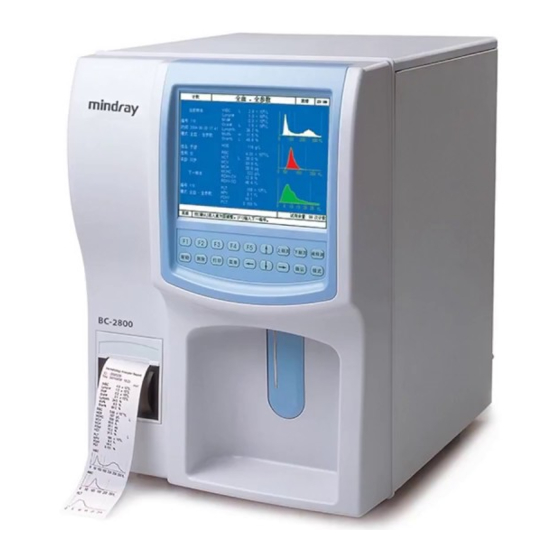
Page 1: Service Manual
BC-2800 Auto Hematology Analyzer Service Manual... - Page 3 Mindray equipment. No part of this can be disseminated for other purposes. In the event of inadvertent or deliberate publication, Mindray intends to enforce its rights to this work under copyright laws as a published work. Those having access to this work may not copy, use, or disclose the information in this work unless expressly authorized by Mindray to do so.
- Page 4 This equipment must be operated by skilled/trained clinical personnel. Warning It is important for the hospital or organization that employs this equipment to carry out a reasonable maintenance schedule. Neglect of this may result in machine breakdown or injury of human health. BC-2800 Auto Hematology Analyzer...
- Page 5 Safety, Reliability and Performance Mindray is not responsible for the effects on safety, reliability and performance of the BC-2800 Hematology Analyzer if: ■ assembly operations, extensions, re-adjusts, modifications or repairs are carried out by persons other than those authorized by Mindray.
-
Page 6: Return Procedure
Copyright Return Policy Return Procedure In the event that it becomes necessary to return a unit to Mindray, the following procedure should be followed: Obtain return authorization. Contact the Mindray Service Department and obtain a Customer Service Authorization (Mindray) number. The Mindray number must appear on the outside of the shipping container. -
Page 7: Table Of Contents
6.7 Printing Management......................6-26 6.8 Adjusting Sample Probe and Replacing Probe Wipe ............6-28 Chapter7 Troubleshooting ..................7-1 7.1 Error Codes .......................... 7-2 7.2 Solutions ..........................7-3 Chapter8 List of Spare Part.................... 8-1 Appendix BC-2800 Error Message ................A-1 BC-2800 Auto Hematology Analyzer... -
Page 9: Chapter1 Hardware
To monitor such system status as the +48V, +12V and -12V supplies of the analog board, the +3.3V and +12V supplies of the CPU board itself and the temperature of the whole analyzer. To receive the keypad signal and control the keypad buzzer and LCD backlight. BC-2800 Auto Hematology Analyzer (V1.0) 1- 1... - Page 10 To generate control signals to control the valves, aperture zapping, HGB LED, current source and digital pot. To drive and turn on the LCD and adjust the contrast. To drive the keyboard, printer and floppy drive. BC-2800 Auto Hematology Analyzer (V1.0)
-
Page 11: Power Supply
+3.3V supply is also further converted into a +1.5V supply to power the FPGA. The +12.8V supply serves the CPU board only. Figure 1-2 Power distribution of the CPU board BC-2800 Auto Hematology Analyzer (V1.0) 1- 3... - Page 12 Figure 1-3 Arrangement of the CPU Clock The X1, X4 and X2 are external crystal oscillators whose frequencies are 45MHz, 45MHz and 24MHz respectively. The clock output of the CPU, BCLKO, is main clock signal of the CPU board. BC-2800 Auto Hematology Analyzer (V1.0)
-
Page 13: Cpu And Peripheral Devices
The Watch-Dog-Timer (WDT) is TI TPS3828. It monitors the running of the software. The CPU must send a feedback to the WDT every 1.6s, otherwise the WDT will force the CPU to restart. BC-2800 Auto Hematology Analyzer (V1.0) 1- 5... - Page 14 CPU on-line. 1.4.8 LEDs When D1 is on, it means +3.3V is functioning properly. When D9 is on, it means +12.8V is functioning properly. When D5 is on, it means the system is reading BC-2800 Auto Hematology Analyzer (V1.0)
- Page 15 DOM. When D7 is on, it means the FPGA has been configured and is functioning properly. When D20 is on, it means the FPGA is restarting; The D11~D18 indicate the system status as defined by the software. BC-2800 Auto Hematology Analyzer (V1.0) 1- 7...
-
Page 16: Analog Inputs And Outputs
1.5.3 Signals of LCD Contrast The Super I/O generates PWM signals that are then integrated to output a 0~2.5V analog signal to control the LCD contrast. The user can adjust the contrast through the software interface. BC-2800 Auto Hematology Analyzer (V1.0) -
Page 17: Digital Inputs And Outputs
PS/2). The software will automatically adapt to the connected printer or the floppy drive. The Super I/O provides a keyboard interface and a mouse interface (COM3 and COM4). Note that the BC-2800 does not support the mouse yet. 1.6.3 GPIOs 1 Signals of the Start key The FPGA detects the input signal, which will turn low when the Start key is pressed. - Page 18 5 Signals controlling valves and pumps The Super I/O outputs 20 control signals to control the valves and pumps through the driving board. Since the BC-2800 only has 1 pump and 11 valves, the redundant lines and ports are reserved.
-
Page 19: Driving Board
Figure 1-8 Switching control circuit 1. Photocoupling circuit The photocoupling circuit mainly consists of the photocoupler and resistors. It provides 16 TTL outputs to the valves and pumps. The photocoupler, TLP521-2, BC-2800 Auto Hematology Analyzer (V1.0) 1- 11... - Page 20 The driving voltage of the valves and pumps are 12V (TTL). The circuit mainly consists of ULN2068. In the BC-2800, the circuit can maximum drives 14 valves and 2 pumps. The fluidic system decides which pumps or valves are to be actually used.
- Page 21 The testable signals are: control signals of valves and pumps, sequence signals of the motors, valves, position signals sent by the position transducers, serial communication signals, reset signals and voltage signals of the power supplies. BC-2800 Auto Hematology Analyzer (V1.0) 1- 13...
-
Page 22: Display Unit
The adapter incorporates two FPC/FFC connectors, J2 and J3. The J3 is for the BC-2800 display while the J2 is reserved for other Mindray analyzer. Only the J2 is installed for the BC-2800. The J1 serves to connect the LCD signal cable. - Page 23 Hardware Figure 1-10 Schematic of the adapter BC-2800 Auto Hematology Analyzer (V1.0) 1- 15...
-
Page 24: Functions Of The Keypad Adapter
The backlight board uses an independent 12V power supply and receives the control signals through photocouplers. The transistor is used to help control the LED so that the power indicator can be turned on even when something is wrong with the MCU. 1-16 BC-2800 Auto Hematology Analyzer (V1.0) - Page 25 The buzzer is controlled by a DC signal (5V DC; current<40mA). The 5V supply of the buzzer is isolated from the VDD and the control signal is received through a photocoupler (TLP521-2)that is controlled by a current around 10mA. Figure 1-12 Buzzer control BC-2800 Auto Hematology Analyzer (V1.0) 1- 17...
-
Page 27: Chapter2 Fluidic System
Chapter 2 Fluidic System 2.1 Fluidic system prepares diluent for the whole blood and prediluted modes counts blood cells and measures HGB concentration dispenses diluent implements the flush, startup and cleaning cycles controls vacuum/pressure BC-2800 Auto Hematology Analyzer (V1.0) 2- 1... -
Page 28: Construction Of Fluidic System
Sleeve Left and right photo-couplers Retaining ring Figure 2-1 Sample probe assembly Mount 2.2.2 Syringe assembly 2.2.3 Pump Assembly 2.2.4 Volumetric metering unit 2.2.5 Right valve panel and front panel See Chapter 3 Disassembling Instructions. BC-2800 Auto Hematology Analyzer (V1.0) -
Page 29: Composition Of Fluidic System
The solenoid valve is ASCO458. Totally 11 valves are used, 7 three-way valves and 4 two-way valves. The two syringes, 10mL and 50uL, are made by Mindray. The aperture is Ø80. The sample probe has two layers and its surface is polished, making the probe easy to clean. -
Page 30: Functional Modules
The aspiration/dispensing module includes a motor that drives the 50 uL and 10 mL syringes, the former for aspirating/dispensing the whole blood sample and the latter for aspirating/dispensing the prediluted sample, diluent and lyse. See the figure below for details. BC-2800 Auto Hematology Analyzer (V1.0) - Page 31 Service tip: Note that the length and type of the buffer tubing shall not be changed. 2.4.2 Counting module The counting module mainly consists of the bath, valve 1 and 2, vacuum filter, metering tube, negative pressure and other supporting components, as figure below shows. BC-2800 Auto Hematology Analyzer (V1.0) 2- 5...
- Page 32 By monitoring the counting time, the system can easily know whether the aperture is clean or blocked and feed this information to the service personnel in terms of the aperture voltage so that they can service the BC-2800 Auto Hematology Analyzer (V1.0)
- Page 33 NO end of valve 6.Then the plunger moves upward to dispense the aspirated diluent, through valves 5 and 6 and the buffer tubing, to the sample probe to wash the interior. BC-2800 Auto Hematology Analyzer (V1.0) 2- 7...
- Page 34 The front bath is washed by diluent and the back bath by rinse. The diluent and the rinse are different and cannot replace each other. BC-2800 Auto Hematology Analyzer (V1.0)
- Page 35 1 and the pump and the NC end of valve 2 to establish the vacuum. The pressure value is monitored by the pressure sensor. The pump is an imported American product, whose P/N is 3001-10-07252. BC-2800 Auto Hematology Analyzer (V1.0) 2- 9...
- Page 36 During the mixing process, the airway should be well drained, or the trapped liquid will affect the quantity of the bubbles as well as the dilution. 2-10 BC-2800 Auto Hematology Analyzer (V1.0)
- Page 37 Likewise, the waste of the probe wipe is discharged to the outside when valves 9 and 10 are open. Bath Negative pressure assembly chamber Waste exit Pump Probe Wipe Figure2-9 Waste discharging module BC-2800 Auto Hematology Analyzer (V1.0) 2- 11...
-
Page 38: Counting Procedure
When analyzing a prediluted sample, the operator should first collect 20μL of capillary sample and dispense 1.6mL of diluent from this analyzer to predilute the sample. Then the operator should present the prediluted sample to the analyzer, 2-12 BC-2800 Auto Hematology Analyzer (V1.0) - Page 39 Figure 2-11 Diluting procedure of prediluted mode 2.5.1.3 Volume range of blood cells After reacting with the diluent and lyse, the cell volumes mainly fall into the following ranges: WBC: 30~350 RBC: 25~250 PLT: 2~30 BC-2800 Auto Hematology Analyzer (V1.0) 2- 13...
-
Page 41: Chapter3 Disassembling The Analyzer
Figure 3-1 Front view Rear view: 1 --- Power switch 2 --- Equipotentiality 3 --- Waste Outlet (Red) 4 --- Lyse Inlet (Orange) 5 --- Rinse Inlet (Blue) 6 --- Diluent Inlet (Green) Figure3-2 Rear view BC-2800 Auto Hematology Analyzer (V1.0) 3- 1... - Page 42 Left view: 1 --- RS232 Port1 (for the scanner) 2 --- Parallel Port 3 --- RS232 Port 2 (for the computer) 4 --- Power Interface of Floppy Disk Drive 5 --- Keyboard Interface Figure3-3 Left view BC-2800 Auto Hematology Analyzer (V1.0)
-
Page 43: Disassembling The Main Unit
Figure3-4 Removing the left, right and top covers 3.2.2 Removing the back plate and the fixing plate of the power module: As the figure below shows, remove the retaining screws (totally 10) to remove the plates. BC-2800 Auto Hematology Analyzer (V1.0) 3- 3... - Page 44 Disassembling the Analyzer Figure 3-5 3.2.3 Removing the front cover As the figure below shows, remove the retaining screws (totally 6) to remove the cover. Figure3-6 BC-2800 Auto Hematology Analyzer (V1.0)
- Page 45 As the figure below shows, remove the retaining screws (totally 7) to remove the keypad. Figure3-8 3.2.6 Removing the LCD and adaptor As the figure below shows, remove the retaining screws (4 for each part) to remove the LCD and adaptor. BC-2800 Auto Hematology Analyzer (V1.0) 3- 5...
- Page 46 As the figure below shows, remove the retaining screws (totally 3) to remove the box. Figure3-10 3.2.8Removing the driving board, analog board, CPU board and power board As the figure below shows, remove the retaining screws (totally 18) to remove the boards. BC-2800 Auto Hematology Analyzer (V1.0)
- Page 47 As the figure below shows, remove the retaining screws (totally 2) with a socket wrench. Figure3-12 3.2.10 Removing valves As the figure below shows, remove the retaining screws (two for each valve) to remove the valves. BC-2800 Auto Hematology Analyzer (V1.0) 3- 7...
- Page 48 Disassembling the Analyzer Figure3-13 3.2.11 Removing the sample probe assembly: As the figure below shows, remove the retaining screws (totally 3) to remove the assembly. Figure3-14 BC-2800 Auto Hematology Analyzer (V1.0)
- Page 49 As the figure below shows, remove the retaining screws (totally 4) to remove the assembly. Figure3-15 3.2.13 Removing the vacuum chamber and volumetric metering tube assembly As the figure below shows, remove the retaining screws (4 for each part) to remove the assembly. BC-2800 Auto Hematology Analyzer (V1.0) 3- 9...
- Page 50 Disassembling the Analyzer Figure3-16 3.2.14 Removing the pump assembly As the figure below shows, remove the retaining screws (totally 7) to remove the assembly. Figure3-17 3-10 BC-2800 Auto Hematology Analyzer (V1.0)
- Page 51 Access the Setup→Password screen and enter the administrator password to obtain the administrator authority. Access the Service→Self-test screen. Press [F1] to select the Machine group and press [↑] or [↓] to move the cursor to Elevator motor, as the figure below shows. BC-2800 Auto Hematology Analyzer (V1.0) 3- 11...
- Page 52 Press [ENTER] and an elevator motor screen will pop up, as the figure below shows. Figure3-20 Elevator motor screen Press [↑] to move the sample probe upward and press [→] to move the probe to the top of the bath, as the figure below shows. 3-12 BC-2800 Auto Hematology Analyzer (V1.0)
- Page 53 Loose the retaining screw by a Philips screwdriver, as the figure below shows. Figure 3-22 Removing screws Remove the probe from the wipe block and insert the localizer into the wipe block from the bottom, as the figure below shows. BC-2800 Auto Hematology Analyzer (V1.0) 3- 13...
- Page 54 Warning The probe is sharp and may contain biohazard materials, including controls and calibrators. Avoid any unnecessary contact with the probe and probe area. Follow the steps given below to replace the wipe block: 3-14 BC-2800 Auto Hematology Analyzer (V1.0)
- Page 55 When the connection is done, place the wipe block back to its original position. 3. Follow steps 7~9 according to Section 3.3.1 to fix the sample probe. Figure3-25 Installing probe wipe BC-2800 Auto Hematology Analyzer (V1.0) 3- 15...
-
Page 57: Chapter4 Histograms And Pulse Graphs
4. A histogram that does not show differential result because the peak is in the middle of the histogram. Figure 4-4 5. A histogram that does not show differential result because of increased nucleated erythrocytes, or interference or inadequate hemolysis BC-2800 Auto Hematology Analyzer (V1.0) 4- 1... - Page 58 (check the pulse graph to determine whether there is interference) in the WBC channel. Figure 4-6 7. No lyse reagent or poor hemolysis Figure 4-7 8. Increased granulocytes Figure 4-8 9. Increased lymphocytes Figure 4-9 Tumor patient Figure 4-10 Increased monocytes Figure 4-11 BC-2800 Auto Hematology Analyzer (V1.0)
-
Page 59: Pulse Graphs
Length of normal level controls data should be: WBC:400 ~ 700K RBC:250 ~ 450K PLT:300 ~ 600K Normal pulse graphs Figure 4-12 WBC pulses Figure 4-13 PLT pulses Figure 4-14 RBC pulses Figure 4-15 Normal WBC background pulse BC-2800 Auto Hematology Analyzer (V1.0) 4- 3... - Page 60 Histograms and Pulse Graphs Figure 4-16 Figure 4-17 Pulse of normal RBC background check Pulse of normal PLT background check BC-2800 Auto Hematology Analyzer (V1.0)
- Page 61 (background) obviously (normal sample) Figure 4-22 Severe interference in P Figure 4-23 Severe interference in PLT LT channel and data length increases channel and data length increases obviously (background) obviously (normal sample) BC-2800 Auto Hematology Analyzer (V1.0) 4- 5...
- Page 62 (normal sample) obviously (normal sample) Figure 4-28 Slight interference in RBC Figure 4-29 Inadequate or no hemolysis in channel and data length does not increase WBC channel and data length increases obviously (normal sample) BC-2800 Auto Hematology Analyzer (V1.0)
- Page 63 Figure 4-33 Measuring interference from caused by inverter. Feature: sine wave inverter with cycle of 20~26us Figure 4-34 Insufficient liquid in WBC bath during count Figure 4-35 Insufficient liquid in RBC bath during count BC-2800 Auto Hematology Analyzer (V1.0) 4- 7...
- Page 64 Figure 4-38 Interference in WBC channel from tubing. Feature: data length Figure 4-39 Interference in RBC channel increases, the base line of signal is not from tubing. Feature: data length stable. increases, the base line of signal is not stable. BC-2800 Auto Hematology Analyzer (V1.0)
-
Page 65: Chapter5 Adjustment
Replacement of the aperture(s) or gasket (s) will affect WBC(whole blood), WBC (prediluted), RBC,PLT Enter the Password screen and enter the password – 3210. Press [MENU] to enter the system menu, move the cursor to Setup → Gain and press [ENTER] to enter the Gain screen. BC-2800 Auto Hematology Analyzer (V1.0) - Page 66 WBC(whole blood):gain of the WBC channel in the whole blood mode WBC(prediluted) :gain of the WBC channel in the prediluted mode RBC:gain of the RBC channel HGB:gain of the HGB gain PLT:gain of the PLT channel. BC-2800 Auto Hematology Analyzer (V1.0)
-
Page 67: Chapter 6 Maintenance
Once it occurs, immediately wipe off the spills. If it occurs inside this analyzer, be sure to shut down the power immediately and call Mindray Customer Services Department or the distributor. Otherwise, the service life of this analyzer may be shortened. -
Page 68: Regular Maintenance
In case you spill the reagents on you skin, be sure to wash them off with much water. In case you spill the reagents into your eyes, be sure to immediately wash your eyes with much water and go see a doctor for further treatment. BC-2800 Auto Hematology Analyzer (V1.0) - Page 69 When this analyzer gives alarms for clogging, you can perform the Flush aperture or Zap aperture procedure, or press [F2] at the Count screen to unclog the system. If you see other error messages, see Chapter 7 Troubleshooting, for solutions. BC-2800 Auto Hematology Analyzer (V1.0)
-
Page 70: System Maintenance
Figure 6-1 Entering maintenance screen Press [ENTER] to enter the Maintenance screen, as Figure 6-2 shows. Figure 6-2 Maintenance screen If you want to exit this screen, press [MENU] to enter the system menu and access the BC-2800 Auto Hematology Analyzer (V1.0) - Page 71 Press [ENTER] to prime the tubing with diluent and the priming progress will be displayed at the bottom of the screen, as Figure 6-3 shows. When the priming is done, the screen will return to the initial state. Figure 6-3 Diluent priming screen BC-2800 Auto Hematology Analyzer (V1.0)
- Page 72 Press [ENTER] to prime the tubing with rinse and the priming progress will be displayed at the bottom of the screen, as Figure 6-4 shows. When the priming is done, the screen will return to the initial state. Figure 6-4 Rinse Priming screen BC-2800 Auto Hematology Analyzer (V1.0)
- Page 73 When the priming is done, the screen will return to the initial state. Figure 6-5 Lyse priming screen 6.2.4 Zap Aperture You can perform the Zap aperture procedure to unclog or prevent clogging. Follow the steps given below to do so: BC-2800 Auto Hematology Analyzer (V1.0)
- Page 74 Press [ENTER] to flush the aperture and the flushing progress will be displayed at the bottom of the screen, as Figure 6-7 shows. When the flushing is done, the screen will return to the initial state. BC-2800 Auto Hematology Analyzer (V1.0)
- Page 75 The soaking process will last about 5 minutes and you may press [ENTER] to stop the process any time. Note that a shortened soaking process may not be as effective as a complete one. BC-2800 Auto Hematology Analyzer (V1.0)
- Page 76 Present the cleanser to the probe and press [ENTER] to aspirate the cleanser. Remove the cleanser after the probe has risen up. This analyzer will automatically soak the bath and tubing with the aspirated cleanser. BC-2800 Auto Hematology Analyzer (V1.0) 6-10...
- Page 77 Unscrew and remove the retaining screws with hands or screwdrivers (pointed by the arrows shown in Figure 6-9) on the right plate. Figure6-9 Removing the two screws Follow the arrow shown in Figure 6-10 to push and remove the right plate. BC-2800 Auto Hematology Analyzer (V1.0) 6-11...
- Page 78 Figure 6-10 Removing right plate Remove the screws fixing the shielding box of the bath, as Figure 6-11 shows. Figure 6-11 Shielding box Remove the shielding box to expose the bath, as Figure 6-12 shows. BC-2800 Auto Hematology Analyzer (V1.0) 6-12...
- Page 79 If the lyse is still enough and the tubing is well connected to the analyzer, contact the Mindray Customer Service Department for repair.
- Page 80 Check the bath and its lower hose for residual liquid. If there is, turn off the analyzer and call the Mindray Customer Service Department or the distributor for repair; if not, press [ENTER] and the analyzer will prime the bath with diluent.
- Page 81 When the accumulated analyzed samples reach 4,000, a dialog box will pop up to remind to clean the wipe block. You may move the cursor to Yes and press [ENTER] to start the cleaning, or to No and press [ENTER] to ignore the message. BC-2800 Auto Hematology Analyzer (V1.0) 6-15...
- Page 82 [ENTER] to drain the tubing again. Turn off the analyzer when the screen displays Turn off the analyzer. Wipe this analyzer dry and wrap it up for storage. BC-2800 Auto Hematology Analyzer (V1.0) 6-16...
-
Page 83: System Status
Press [MENU] to enter the system menu and press the appropriate arrow keys to move the cursor to Service → Status, as Figure 6-16 shows. Figure 6-16 Entering status screen Press [ENTER] to enter the Status screen, as Figure 6-17 shows. Figure6-17 Status screen BC-2800 Auto Hematology Analyzer (V1.0) 6-17... -
Page 84: System Self-Test
Service Self-test, as Figure 6-18 shows. Figure 6-18 Entering self-test screen Press [ENTER] to enter the Self-test screen, as Figure 6-19 shows. If you want acquire help information, press [HELP]. BC-2800 Auto Hematology Analyzer (V1.0) 6-18... - Page 85 Aperture(v) It measures the voltage (v) over the aperture. Vacuum It checks whether the vacuum system functions normally. Pressure It checks whether the system flushes the aperture at a normal pressure. BC-2800 Auto Hematology Analyzer (V1.0) 6-19...
- Page 86 This test checks whether the recorder or printer functions normally. If normal, when you press [ENTER], the recorder or printer will print out test page; if abnormal, the screen will display the corresponding error message and you can BC-2800 Auto Hematology Analyzer (V1.0) 6-20...
- Page 87 At the Self-test screen, press [F1] to select the Circuit group, as Figure 6-22 shows. You can test the A/D interrupt at this screen by pressing [ENTER] to see whether the WBC, RBC and PLT signals can be properly converted into digital signals. BC-2800 Auto Hematology Analyzer (V1.0) 6-21...
- Page 88 Chapter 6 Maintenance Figure 6-22 Testing A/D converter BC-2800 Auto Hematology Analyzer (V1.0) 6-22...
- Page 89 Press [MENU] to enter the system menu and press the appropriate arrow keys ([↑][↓][←][→]) to move the cursor to Service→Log, as Figure 6-23 shows. Figure 6-23 Entering log Press [ENTER] to enter the Log screen, as Figure 6-24 shows. Figure 6-24 Log screen BC-2800 Auto Hematology Analyzer (V1.0) 6-23...
- Page 90 Information column displays extra information regarding the event. This analyzer can save maximum 1000 log files and once the maximum number has been reached, the newest log will automatically cover the oldest one. BC-2800 Auto Hematology Analyzer (V1.0) 6-24...
-
Page 91: System Configuration
[PgDn] to go to the previous or next screen. If you want to print out the configuration, press [PRINT]. If you want to acquire help, press [HELP]. BC-2800 Auto Hematology Analyzer (V1.0) 6-25... -
Page 92: Printing Management
Once the system finds the error has been removed, it will resume printing and process the tasks from the first one. Note that you cannot change the sequence of the queued tasks. BC-2800 Auto Hematology Analyzer (V1.0) 6-26... - Page 93 You can perform the following operations at the Print screen: Press [↑] or [↓] to select the desired task. Press [DEL] to delete the selected task. Press [HELP] to display the help information. Press [MENU] to return to the system menu. BC-2800 Auto Hematology Analyzer (V1.0) 6-27...
-
Page 94: Adjusting Sample Probe And Replacing Probe Wipe
Chapter 6 Maintenance Adjusting Sample Probe and Replacing Probe Wipe See Chapter 3.3. BC-2800 Auto Hematology Analyzer (V1.0) 6-28... -
Page 95: Chapter7 Troubleshooting
The chapter deals with the codes, possible causes and solutions of the errors. If the error remains after you have tried the recommended method, call Mindray Customer Service Department or the distributor. This chapter consists of two parts, the first part dealing with the errors and assigned error codes and the second possible causes and recommended solutions. -
Page 96: Error Codes
Rotation motor 4002 4003 4004 Elevator motor error error error 4005 A/D error 4008 Vacuum error 4009 Pressure error 400B Diluent out 400C Rinse out 400D Waste full Dynamic 8001 File error 8002 memory error BC-2800 Auto Hematology Analyzer (V1.0) -
Page 97: Solutions
Access Setup → Password to gain the administrator authority. Access Setup → Settings → Gain to adjust the HGB blank voltage to 3.4~4.8V (4.5V recommended). If the error still remains, turn off this analyzer and call Mindray Customer Service Department or the distributor. - Page 98 → Count and adjust the WBC count time. If the error still remains, turn off this analyzer and call Mindray Customer Service Department or the distributor. 7.2.7 RBC Clog This error message occurs when the actual RBC count time is greater than the...
- Page 99 If the error still remains, access Setup → Password to gain the administrator authority and then access Setup → Settings → Count and adjust the RBC count time. If the error still remains, turn off this analyzer and call Mindray Customer Service Department or the distributor. BC-2800 Auto Hematology Analyzer (V1.0)
- Page 100 Possible causes: recording paper has run out or is not correctly installed. Solution: Check whether the recording paper has run out. If so, load new paper; if not, re-install the existing paper. If the error still remains, call Mindray Customer Service Department or the distributor. 7.2.16 Recorder Too Hot Possible causes: the recording head overheats.
- Page 101 Access Service → Self-test → Tubing and test the filter. The error is cleared if the result is normal. If not, call Mindray Customer Service Department or the distributor. 7.2.23 Real-Time Clock Error Something is wrong with the clock. Access Setup →...
- Page 102 Something is wrong with the A/D converter on the CPU board. Solution: Access Service → Self-test → Circuit. Test the A/D interrupt. The error will be cleared if the test result is normal. Otherwise, call Mindray Customer Service Department or the distributor. 7.2.28 Vacuum Error The system does not reach the expected vacuum within the given time.
- Page 103 Empty the container, or change a new container to receive the waste and re-set the waste container volume. 7.2.33 File Error Something is wrong with file saving. Turn off the analyzer and call Mindray Customer Service Department or the distributor. 7.2.34 Dynamic Memory Error Something is wrong with the system memory.
- Page 105 2800-20-28847 Nut of 50µl syringe 2800-20-28848 Bolt of 50µl syringe 2800-20-28849 Connection wire of inverter 2800-21-28728 Shielding box cover assembly 2800-21-28788 Shielding box assembly 2800-30-28650 CPU board 2800-30-28652 Analog board 2800-30-28654 Driving board 2800-30-28664 Keypad BC-2800 Auto Hematology Analyzer (V1.0)
- Page 106 3001-10-07059 Sample probe 3001-10-07252 Diaphragm pump 3001-20-07072 Transformer 3001-20-07245 Three-way valve (ASCO) 3001-20-07246 Two-way valve (ASCO) 3001-30-06880 Sample probe assembly 3001-30-07021 Vacuum chamber assembly 900E-10-04913 Inverter 3001-10-07068 Tubing(ID1/16’, OD1/8’) M90-100035--- Tubing(ID0.02, OD0.06) M90-100071--- Tubing(ID3/32’, OD5/32’) BC-2800 Auto Hematology Analyzer (V1.0)
-
Page 107: Appendix Bc-2800 Error Message
Appendix BC-2800 Error Message CODE Error Message Information 0401 Envir. Temp. Abnormal 0402 Background abnormal 0403 HGB error 0404 HGB adjust 0405 WBC clog 0406 WBC bubbles 0407 RBC clog 0408 RBC bubbles 0801 Communication error 0802 Scanner error 0803... - Page 108 P/N:2800-20-28975...
Need help?
Do you have a question about the BC-2800 and is the answer not in the manual?
Questions and answers
Hola! Tengo un error en mi BC 2800, me aparecio error: presion baja, ya realice el auto test y ahora me dice que la presión es normal, pero no se borra el error de la pantalla principal y no puedo usar el equipo
If a low pressure error persists on the Mindray BC-2800 even after an auto test indicates normal pressure, you should call Mindray Customer Service Department or the distributor.
This answer is automatically generated
WBC bubbles
WBC bubbles in the Mindray BC-2800 are caused when the actual WBC count time is less than the preset WBC count time by 2 seconds. Possible causes include:
1. Insufficient diluent or rinse.
2. Loose tubing connections.
3. Inappropriate WBC count time setting.
This answer is automatically generated
Abnormal background display on the screen
An abnormal background error on the Mindray BC-2800 can be caused by several factors:
1. Dirty or Contaminated System – Cleaning tests should be performed to remove any buildup or debris.
2. Electrical Issues – Poor grounding or electrical noise can interfere with the system.
3. Reagent Problems – Ensure the use of genuine Lyse reagent.
4. Electrode Issues – A greenish color on the electrode inside the counting bath may indicate a soldering problem between the silver plate and the copper wire. Resoldering or replacing the bath may be necessary.
5. Faulty Tubing or Connections – Loose tubing connections can contribute to the error.
6. Startup Procedure Needed – Running the startup procedure by pressing [F3] at the Count screen may resolve the issue.
If the issue persists after these steps, contacting Mindray Customer Service or a distributor is recommended.
This answer is automatically generated
A/d interrupt abnormal
"A/D interrupt abnormal" on the Mindray BC-2800 indicates a problem with the analog-to-digital (A/D) interrupt function. This may suggest an issue with the system’s ability to properly convert analog signals to digital data, which could affect test accuracy. The test for this function is done by selecting “A/D interrupt” in the “Circuit” group. If the test result is not normal, service may be required.
This answer is automatically generated