
Related Manuals for Mindray BC-2800


Summary of Contents for Mindray BC-2800
- Page 1 BC-2800 BC-2800 A Au u t t o o Hem Hemat ato o l l o o g g y A y An n al aly y zer Operation Manual Operation Manual...
- Page 3 Mindray, nor the rights of others. Mindray does not assume any liability arising patent rights of Mindray, nor the rights of others. Mindray does not assume any liability arising out of any infringements of patents or other rights of third parties.
-
Page 4: Warranty
Return turn Procedure Procedure In the event that it becomes necessary to return a unit to Mindray, the following procedure In the event that it becomes necessary to return a unit to Mindray, the following procedure should be followed: should be followed: 1. - Page 5 Freight policy. The customer is responsible for freight charges when equipment is shipped to Mindray for service (this includes customs charges). Company Contact Addr ess: Mindray Building, Keji 12th Road South, Hi-tech Industrial Park, Nanshan, Shenzhen 518057 P.R.China...
-
Page 7: Safety Symbols
Safety Symbo ls Symbol Warning Condition Action Wear standard laboratory Biohazard: Consider materials attire, glove and follow safe (specimens, controls, calibrators, laboratory procedures when components that contain or have contacted handling any material in the human blood) being potentially laboratory. - Page 8 1.3 System Introd uctio n 1.3.1 Name and Intended Use The full name of this analyzer is BC-2800 Auto Hematology Analyzer. It is a quantitative, automated hematology analyzer and leukocyte differential counter for In Vitro Diagnostic Use in clinical laboratories.
-
Page 9: Supplementary Data
Be sure that any products to be used have been tested and certified by the manufacturer. Mindray recommends the reagents described in Chapter 1.5.10 Reagents . Do not use the reagents or controls from different suppliers, or else the analyzer may not perform as promised and even be damaged. - Page 10 The “calibrators” and “controls” that appear in the rest of this manual refer to the calibrators and controls to be used on this analyze only. You shall order them only from Mindray customer service department or the distributor.
- Page 11 Introduction Introduction 1.4 Principles of Principles of Ope Operation ration 1.4.1 1.4.1 Me Measuring Prin asuring Prin cipl cipl e e This analyzer adopts the Coulter Principle to count WBC, RBC and PLT cells and to draw their This analyzer adopts the Coulter Principle to count WBC, RBC and PLT cells and to draw their corresponding histograms.
- Page 12 Introduction Introduction When analyzing a prediluted sample, the operator should first collect 20 L capillary specimen When analyzing a prediluted sample, the operator should first collect 20 L capillary specimen and dispense 1.6mL diluent from this analyzer to predilute the specimen. Then the operator and dispense 1.6mL diluent from this analyzer to predilute the specimen.
- Page 13 Introduction Introduction Upper sensor Upper sensor Upper sensor Upper sensor Lower sensor Lower sensor Lower sensor Lower sensor 1 1 E E m m p p t t y y w w h h e e n n s s t t a a r r t t 2 2 L L i i q q u u i i d d s s u u r r f f a a c c e e f f a a l l l l d d o o w w n n t t h h r r o o u u g g h h t t h h e e volumeritc tube volumeritc tube...
- Page 14 Introduction Introduction Based on the WBC histogram, this analyzer calculates Lymph , Mid and Gran as Based on the WBC histogram, this analyzer calculates Lymph , Mid and Gran follows, follows, Lymph Lymph ×...
- Page 15 Introduction 1.4.4.6 HCT, MCH and MCHC This analyzer calculates the HCT (%), MCH(pg) and MCHC(g/L) as follows: RBC L MCV fL × HCT HGB L MCH pg RBC L MCHC × 1.4.4.7 RDW-CV Based the WBC histogram, this analyzer calculates the CV (Coefficient of Variation) of the erythrocyte distribution width.
- Page 16 Introduction 1.5 Specifications 1.5.1 Parameter Descr ipti on Table 1-3 Directly measured parameters and histograms Parameter Abbr eviation Default Unit White Blood Cell or leukocyte Hemoglobin Concentration Red Blood Cell or erythrocyte Platelet WBC histogram RBC histogram PLT histogram Table 1-4 Parameters derived from histograms Parameter Abbr eviation...
-
Page 17: Transportation And Storage Environment
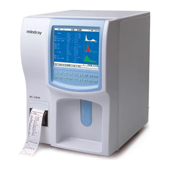
Introduction Introduction 1.5.11 1.5.11 Power Power Voltage Voltage AC 220V±15% AC 220V±15% 50/60Hz±1Hz 50/60Hz±1Hz AC 1 1 10V±15% 10V±15% 50/60Hz±1 50/60Hz±1Hz Consumption Consumption 180 VA 180 VA Fuse Fuse 250 V V or or 125V 125V 1.5.12 1.5.12 Am Am bi bi ent... - Page 18 Introduction Introduction 1.6 System O System Operation peration 1.6.1 1.6.1 Ma Main in Unit Unit Figure 1-5 Front view Figure 1-5 Front view 1 ---- LCD 1 ---- LCD 2 ---- Keypad 2 ---- Keypad 3 ---- Recorder 3 ---- Recorder 4 ---- Power Indicator 4 ---- Power Indicator...
- Page 19 Introduction Introduction Figure Figure 1-6 1-6 Back Back view view 1 --- Power switch 1 --- Power switch 2 --- 2 --- Equipotentiality Equipotentiality 3 --- Waste Outlet (Red) 3 --- Waste Outlet (Red) 4 --- Lyse Inlet (Orange) 4 --- Lyse Inlet (Orange)
- Page 20 Introduction Introduction Figure 1-7 Left view Figure 1-7 Left view 1 --- RS232 Port1 (for 1 --- RS232 Port1 (for the scanner) the scanner) 2 --- Parallel (also for the 2 --- Parallel (also for the floppy disk drive) floppy disk drive) 3 --- RS232 Port 2(for 3 --- RS232 Port 2(for the computer)
-
Page 21: Display A Reas
Introduction 1.6.2 Display A reas Title Count Mode System System Status time Window Error Messages Reagent Status MENU On-line Help Figure 1-8 Display areas Title area Displays the screen title, such as Count or Review. Count Mode areaDisplays current count mode. Six count modes are available. Whole Blood - All Parameter Prediluted - All Parameter Whole Blood - WBC/HGB... -
Page 22: Input Devices
Introduction 1.6.3 Input Devices The input devices includes a [START] key, 18-key keypad and PS/2 keyboard(optional). Note If your analyzer is not equipped with a PS/2 keyboard, you will not be able to use the functions controlled by the keyboard only. The [START] key is located behind the sample probe. -
Page 23: Screen Saver
Introduction [ → ][ ← ] [ → ][ ← ] position. [F1] [F2] [F3] [F4] [F1] [F2] [F3] [F4] Function keys. [F5] [F5] Other keys Other functions. [START] Starts aspiration. 1.6.4 Screen Saver To extend the service life of the LCD, this analyzer will enter the screen saver if no any operation was done in the past 10 minutes. -
Page 24: System Menu
Introduction 1.6.5 System Menu See Figure 1-10 for the structure of the system menu. Figure 1-10 System menu... -
Page 25: Operation Summary
Introduction 1.7 Operation Summary The BC-2800 can analyze two types of blood specimens – whole blood samples and prediluted blood samples. See Table 1-7. Table 1-7 Operation summary Do preliminary checks (reagent and waste containers, tubing connections, power connections and the like) -
Page 26: Installation
When you receive this analyzer, carefully unpack and check it. File a claim immediately with the shipping carrier if you find any physical damage. Compare the delivered goods against the packing list to ensure that the shipment is complete. If the shipment appears incomplete, notify Mindray Customer Service Department or your distributor immediately. -
Page 27: Space Requi Rement
Installation Installation Requir ements 2.2.1 Installation Environment The environment should be as free as possible from dust, mechanical vibrations, loud noises and electrical interference. Avoid proximity to brush-type motors, flickering fluorescent lights and electrical contacts that regularly turn on and off. Avoid placing this analyzer in direct sun or in front of a source of heat or draft. -
Page 28: Tubin G Connection
Insert the tubing end that has no connector into the diluent container, as Figure 2-1 shows and turn the container cover clockwise until secure. Connect the tubing connector to the DILUENT inlet (green) on the back of BC-2800 and turn it clockwise until secure. - Page 29 Insert the tubing end that has no connector into the rinse container, as Figure 2-2 shows and turn the container cover clockwise until secure. Connect the tubing connector to the RINSE inlet (blue) on the back of BC-2800 and turn it clockwise until secure.
-
Page 30: Waste Disposal
Installation Figure 2-3 Lyse container Do the following steps when the installation is done. Enter the lyse volume as instructed by section 7.2.1.1 Setting remaining volumes for reagents . Enter the expiration date as instructed by section 7.2.1.3 Setting expiration dates of reagents. -
Page 31: Loading Recordi Ng Paper
Installation 2.4 Loading Recordi ng Paper Follow the steps given below to install the recording paper. 1. Follow the arrow in the figure below to open the door of the recorder, as Figure 2-4 shows. Figure 2-4 Open the recorder door 2. - Page 32 Installation 4. Push the press bar back and close the recorder door, as Figure 2-7 shows. Figure 2-7 Close recorder door...
-
Page 33: Entering Sample Information
Sample Analysis 3.4 Entering Sample Information You may enter sample information in any of the three modes, ID only, All in fo and Batch edit, depending on the configuration of your analyzer. Note that the Al l info mode cannot co-exist with the other two modes. - Page 34 Sample Analysis press [MENU] and a dialog box will pop up, as Figure3-4 shows. To ignore the entered number, move the cursor to No and press [ENTER]; otherwise, move the cursor to Yes and press [ENTER]. Figure3-4 Dialog box Note When the ID of the next sample is 0 and you have pushed the [START] key, the system will perform the background check.
- Page 35 Sample Analysis Figure 3-5 Entering sample information 1. To enter the sample ID, you may A. Press [] or [] to move the cursor to the edit box right of ID, as Figure 3-5 shows. B. Press [] or [] to move the cursor within the edit box. Press [PgUp] or [PgDn] (or the numeric keys of a keyboard) to enter a digit at the position where the cursor is located.
- Page 36 Sample Analysis Figure3-6 Select Gender 3. To enter the patient name, you may A. Press [] or [] to move the cursor the edit box right of Name B. Use a keyboard to enter the patient name. Press [DEL] if you want to delete the character after the cursor.
- Page 37 Sample Analysis B. To enter the patient in months, you may a. Press [ ] or [ ] to move the cursor to the edit box left of Month. ↑ ↓ b. Press [ ] or [ ] to move the cursor within the edit box. Press [PgUp] or [PgDn] (or ←...
- Page 38 Sample Analysis next field to be edited. 7. To enter the name of the department from which the sample came, you may A. Press [] or [] to move the cursor to the edit box right of Dept. B. Use a keyboard to enter the name of the department (similar to the way you enter patient names).
- Page 39 Sample Analysis box automatically saves the entered item to its pull-down menu, which can be accessed by pressing [ENTER]. Totally 30 items can be saved in the pull-down menu, and you may press [ ] or [ ] to move the cursor to the interested item and press ↑...
- Page 40 Sample Analysis 3.4.3 Batch Edit Mode If your analyzer is configured as Batch edit, you can continuously enter information of a batch of samples. Follow the steps given below to do so. 1. At the Count screen, press [F4] to enter the Batch edit screen, as Figure 3-8 shows. Figure 3-8 Batch edit screen 2.
-
Page 41: Preparing Sampl Es
Sample Analysis 3.5 Preparing Sampl es BC-2800 is capable of analyzing two types of samples - whole blood samples and prediluted samples. Biohazard Consider all materials (specimens, reagents, controls, calibrators, or components that contain or have contacted human blood) as being potentially infectious. - Page 42 D. Be sure to prevent dusts from falling into the prepared diluent. Otherwise, you may acquire misleading result. E. The precision of the analysis results of the prediluted samples vary depending on the operators. Mindray recommends every laboratory evaluate the stability of the results based on its sample quantity and collection method.
- Page 43 Sample Analysis 3.6 Sampl e Analys is To keep this analyzer precise, be sure to run the QC program every day before beginning sample analysis. See chapter 4, Quality Control, for details. 3.6.1 Anal yzi ng Samp les 3.6.1.1 Selecting Analysis Mode At the Count screen, press [MODE] to select one of the six analysis modes.
- Page 44 Sample Analysis Biohazard Consider all materials (specimens, reagents, controls, calibrators, or components that contain or have contacted human blood) as being potentially infectious. Wear standard laboratory attire, glove and follow safe laboratory procedures when handling any material in the laboratory. Warning The probe is sharp and may contain biohazard materials, including controls and calibrators.
- Page 45 Setup Figure 7-28 Selecting parameter unit Press [ ] or [ ] to move the cursor to the desired unit and press [ENTER] to confirm the selection. When you are done selecting units, press[ ] or [ ] to move the cursor to other settings ...
-
Page 46: Reference Range
Setup Figure 7-29 Saving changes 7.2.6 Reference Range You can set a reference range for every parameter. The system will flag any analysis result that exceeds this range with either an H or L. This analyzer divides the patients into 5 patient groups, which are all listed in Table 7-4. - Page 47 Setup Figure 7-30 Setting reference range 7.2.6.1 Selecting patient group Follow the steps given below to select the patient group you want. At the Setup screen, press [F1] to select the Ref. range group. Press [ ] or [ ] to move the cursor to the combo box right of Group. Press [ENTER] to ...
- Page 48 Setup Press [ ] or [ ] to move the cursor to General, Male adults , Female adults , Pediatri c patients or Neonates and press [ENTER] to confirm the selection. When you are done selecting the patient group, press [ ] or [ ] to move the cursor to the ...
- Page 49 Setup Figure 7-33 Setting lower limit for WBC Press [ ] or [ ] to move the cursor within edit box. Press [PgUp] or [PgDn] (or the numeric keys on an external keyboard) to enter a digit at the position where the cursor is located.
- Page 50 Setup press [MENU] and a dialog box will pop up to remind you to save the changes. Press [ ] or [ ] to move the cursor to Yes and press [ENTER] to save the changes and exit to the system menu or move the cursor to No and press [ENTER] to exit to the system menu without saving the changes.
- Page 51 Setup Figure 7-36 Selecting how to mute the beeper 7.2.7.2 Setting LCD contrast Follow the steps given below to adjust the LCD contrast. At the Setup screen, press [F1] to select the Other group. Press [ ] or [ ] to move the cursor to LCD contrast, as Figure 7-37 shows. ...
- Page 52 Setup At the Setup screen, press [F1] to select the Other group. Press [ ] or [ ] to move the cursor to Al arm ti me, as Figure 7-38 shows. Figure 7-12 Setting alarm time Press [PgUp] or [PgDn] to adjust the time. ...
- Page 53 Setup Press [ ] or [ ] to select Black or Blue and press [ENTER] to confirm the selection. Press [ ] or [ ] to move the cursor to other settings you want to change. ...
-
Page 55: Chapter 8 Maintenance
Once it occurs, immediately wipe off the spills. If it occurs inside this analyzer, be sure to shut down the power immediately and call Mindray Customer Services Department or the distributor. Otherwise, the service life of this analyzer may be shortened. -
Page 56: Recommended Regular Maintenance
Maintenance 8.1.2 Recommended Regular Maintenance Maintenance Content of Maintenance Period Everyday If you are to use this analyzer 24 hours a day, be sure to perform the E-Z cleanser cleaning procedure everyday. Run the QC program everyday. See Chapter 4 Quality Control for details. -
Page 57: System Status
Maintenance 8.3 System Status The items displayed in the Status screen reflect how the system is functioning and contribute significantly to diagnosing system errors. You may follow the instructions given below to check those items. Press [MENU] to enter the system menu and press the appropriate arrow keys to move the cursor to Service ... - Page 58 Maintenance Note that you can only view the displayed status items without changing them. If any of the displayed item exceeds the given range, see Chapter 9 Troubleshooting for solutions.
-
Page 59: System Self-Test
Maintenance 8.4 System Self-Test The system self-test is a major way to locate system errors. Follow the instructions given below to view and check the available self-tests items. Press [MENU] enter system menu press appropriate arrow keys([][][][])to move the cursor to Service ... -
Page 60: Testing Motors And Recor Der/Prin Ter
Maintenance Circuit, as shown on the left of the screen. You can switch between the groups by pressing [F1] and once a group is selected, the test items, including their test results (if available), belonging to that group will be displayed on the right of the screen. You may press [PRINT] to print out the displayed results. -
Page 61: Testing Valves
Maintenance Figure 8-21 Testing mechanic parts Syringe motor The syringe motor controls the aspiration volume. This test checks whether the motor functions normally. Rotation motor The rotation motor rotates the sample probe inside the analyzer. This test checks whether the motor functions normally. - Page 62 Maintenance test. Otherwise, something may be wrong with the valve. Figure 8-22Testing valves 8.3.4 Testing Circuits At the Self-test screen, press [F1] to select the Circuit group, as Figure 8-23 shows. You can test the A/D inter rupt at this screen by pressing [ENTER] to see whether the WBC, RBC and PLT signals can be properly converted into digital signals.
- Page 63 Maintenance 8.5 Log The log records all the major events taking place during the running of this analyzer. It helps the service engineers diagnose system errors. Press [MENU] to enter the system menu and press the appropriate arrow keys ([ ][][][]) to move the cursor to ServiceLog, as Figure 8-24 shows.
- Page 64 Maintenance the left of the screen. All the recorded are listed on the right of the screen by default. You can press [F1] to select the interested group and the right of the screen will display the events of the selected group only.
-
Page 65: System Configuration
Maintenance 8.6 System Configur ation To view the system configuration, press [MENU] to enter the system menu, and then press the appropriate arrow keys to move the cursor to Service Press [ENTER] to enter the Config screen, as Figure 8-26 shows, where you can only view the system configuration without changing it. -
Page 66: Printing Management
Maintenance 8.7 Printing Management Press the [MENU] to enter the system menu and press the appropriate arrow keys ([][][][])to move the cursor to ServicePrint, as Figure 8-27 shows. Figure 8-27 Entering print screen Press [ENTER] to enter the Print screen, as Figure 8-28 shows. The printing tasks are queued in this screen, where you can view the all tasks and delete those waiting to be processed. - Page 67 Maintenance You can perform the following operations at the Print screen: Press [ ] or [ ] to select the desired task. ↑ ↓ Press [DEL] to delete the selected task. Press [HELP] to display the help information. Press [MENU] to return to the system menu.
- Page 68 Maintenance 8.8 Adjusting Sample Probe and Probe Wip e Bl ock The relative position between the sample probe and probe wipe block has influence on the analysis results. In the accessory box, there is a sample probe localizer, as Figure 8-30 shows.
- Page 69 Maintenance Figure 8-32 Sample probe above the bath 6. Loose the retaining screw by a screwdriver, as Figure 8-33 shows. Figure 8-33 Removing screws 7. Remove the probe from the wipe block and insert the localizer into the wipe block from the bottom, as Figure 8-34 shows.
- Page 70 Maintenance Figure 8-34 Using localizer 8. Insert the probe into the wipe block until it reaches the localizer, as Figure 8-35 shows. Figure 8-35 Inserting sample probe into wipe block 9. Retighten the screw to fix the probe and remove the localizer to wrap up the adjustment. 8.8.2 Replacin g Probe Wipe Block Biohazard...
- Page 71 Maintenance 2. Pull the loosen sample probe upward to remove the wipe block and disconnect the tubes from the wipe block (pay attention to the correspondence between the tubes and the connectors ), as Figure 8-36 shows. 3. Refer to Chapter 8.7.1 and do the steps 7~9 of fix t he sample probe. Figure 8-36 Installing wipe block...
-
Page 73: Troubleshooting
The chapter deals with the codes, possible causes and solutions of the errors. If the error remains after you have tried the recommended method, call Mindray Customer Service Department or the distributor. This chapter consists of two parts, the first part dealing with the... -
Page 74: Error Codes
Troubleshooting 9.1 Error Codes The errors recorded in the log are presented in the error codes. See Table 9-1 for the correspondence between the errors and error codes. Table 9-1 Errors and codes Code Error Code Error Code Error Envir. Temp. Background 0401 0402... - Page 75 Circuit. Test the A/D interrupt as instructed by Chapter 8.4.4. → → The error will be cleared if the test result is normal. Otherwise, call Mindray Customer Service Department or the distributor. 9.2.2 Dynamic Memory Error Something is wrong with the system memory.
- Page 76 After the adjustment, test the actual count time again and make sure the difference is within 2 seconds. 3. If the error still remains, call Mindray Customer Service Department or the distributor. 9.2.6 RBC Bubbles This error message occurs when the actual RBC count time is less than the preset RBC count time by 2 seconds.
- Page 77 Count and adjust the RBC count time as instructed by Chapter 7.2.5.2. 4. If the error still remains, turn off this analyzer and call Mindray Customer Service Department or the distributor. 9.2.7 WBC Clog This error message occurs when the actual WBC count time is greater than the preset WBC count time by 2 seconds.
- Page 78 Settings Count and adjust the WBC count time as instructed by Chapter 7.2.5.2. 4. If the error still remains, turn off this analyzer and call Mindray Customer Service Department or the distributor. 9.2.9 Background Abnormal At least one parameter failed the background check.
-
Page 79: Printer Out O F Paper
Access Service Self-test Tubing and test the filter as instructed by Chapter 8.4. The error is cleared if the result is normal. If not, call Mindray Customer Service Department or the distributor. 9.2.15 Environ mental Temperatur e Abnor mal Possible causes abnormal environmental temperature or malfunctioning temperature sensor. - Page 80 Call Mindray Customer Service Department or the distributor. 9.2.18 Recorder Too Hot Possible causes the recording head overheats. Stop using the recorder. If the error repeats, call Mindray Customer Service Department or the distributor. 9.2.19 Press Bar Up The press bar of the recorder is up.
- Page 81 Chapter 8.4. 8.4.2 2 . . The error will be cleared if the result is normal. Otherwise, call Mindray Customer Service The error will be cleared if the result is normal. Otherwise, call Mindray Customer Service Department or the distributor.
- Page 82 Troubleshooting Troubleshooting Turn off the analyzer and call Mindray Customer Service Department or the distributor. Turn off the analyzer and call Mindray Customer Service Department or the distributor. 9.2.28 9.2.28 Rinse Out Rinse Out Possible causes Possible causes insufficient rinse or wrong rinse insufficient rinse or wrong rinse volume setting.
- Page 83 Chapter Chapter 8.4.1 8.4.1. The error will be cleared if the result is normal; otherwise, call Mindray Customer Service . The error will be cleared if the result is normal; otherwise, call Mindray Customer Service Department or the distributor.
- Page 85 A.4.1.2 Programming Programming If the Handshake is off, BC-2800 will transmit the body of the text without acknowledging the If the Handshake is off, BC-2800 will transmit the body of the text without acknowledging the presence of an external computer.
- Page 86 NACK (15 Hex), then BC-2800 will execute Step 3 once again. If anything else is received, BC-2800 will send ETX (03 Hex) once 3 once again. If anything else is received, BC-2800 will send ETX (03 Hex) once more.
- Page 87 Communication Communication Mid#[10 Mid#[10 ###.# ###.# Gran#[10 Gran#[10 ###.# ###.# Lymph%[%] Lymph%[%] ##.# ##.# Mid%[%] Mid%[%] ##.# ##.# Gran%[%] Gran%[%] ##.# ##.# RBC[10 RBC[10 ##.# ##.# HGB[g/L] HGB[g/L] MCHC[g/L] MCHC[g/L] #### #### MCV[fL] MCV[fL] ###.# ###.# MCH [pg] [pg] ###.# ###.# RDW-CV[%] RDW-CV[%]...
- Page 88 [EOF] [EOF] For all the data formats, if the data are mark “*” in BC-2800, then “*” (2A Hex) will be For all the data formats, if the data are mark “*” in BC-2800, then “*” (2A Hex) will be transmitted to the external computer.
- Page 89 Communication PLT[10 #### Lymph#[10 ###.# Lymph%[%] ##.# Gran#[10 ###.# Gran%[%] ##.# HCT[%] ##.# MCV[fL] ###.# MCH[pg] ###.# MCHC[g/L] #### WBC Limit[10 ###.# RBC Limit[10 #.## HGB Limit[g/L] PLT Limit[10 #### Lymph# Limit[10 ###.# Lymph% Limit[%] ##.# Gran# Limit[10 ###.# Gran% Limit[%] ##.# HCT Limit[%] ##.#...
- Page 90 Communication Year #### Hour Minutes WBC[10 ###.# RBC[10 #.## HGB[g/L] PLT[10 #### Lymph#[10 ###.# Lymph%[%] ##.# Gran#[10 ###.# Gran%[%] ##.# HCT[%] ##.# MCV[fL] ###.# MCH[pg] ###.# MCHC[g/L] #### Body of the text end If handshake is selected [EOT] If handshake is not selected [EOF] If handshake is selected [ETX]...
Need help?
Do you have a question about the BC-2800 and is the answer not in the manual?
Questions and answers