Table of Contents
Advertisement
Quick Links
Advertisement
Table of Contents

Related Manuals for Mindray BA-88A


Summary of Contents for Mindray BA-88A
- Page 1 BA-88A Semi-auto Chemistry Analyzer Operation Manual...
- Page 3 This manual may refer to information protected by copyrights or patents and does not convey any license under the patent rights of Mindray, nor the rights of others. Mindray does not assume any liability arising out of any infringements of patents or other rights of third parties.
- Page 4 Mindray or repairs by people other than Mindray authorized personnel.
- Page 5 Company Contact Manufacturer: Shenzhen Mindray Bio-Medical Electronics Co., Ltd. Mindray Building, Keji 12th Road South, Hi-tech Industrial Park, Address: Nanshan, ShenZhen518057, P.R. China Tel: +86 755 26582479 26582888 Fax: +86 755 26582934 26582500 EC Representative Name: Shanghai International Holding Corp. GmbH (Europe) Address: Eiffestraβe 80, Hamburg 20537, Germany...
-
Page 7: Preface
Preface Before using the system, please read this operation manual thoroughly for relevant operation instructions. Please keep this manual properly for convenient use. Intended Reader This manual is geared for clinical professionals to: Operate the system; Maintain and troubleshoot the system; Learn about the system operation. - Page 8 Labels The labels attached to the surface of the instrument use symbols to clarify the meaning of the text. If any of the labels peels off, contact our company customer service department or your local distributor for replacement. The chart below explains the symbols on the labels.
- Page 9 Graphics All graphics, including screens, are for illustration purpose only and must not be used for any other purposes.
- Page 10 Safety Precautions Observe theses safety precautions when using the system. Ignoring any of the precautions may lead to personal injury or equipment damage. WARNING If the instrument is used in a manner not specified by our company, the protection provided by the system may be impaired. Preventing Electric Shock Please observe the following instructions to prevent electric shock.
- Page 11 Preventing Personal Injury Caused by Photometer Lamp Please observe the following instructions to prevent personal injury caused by photometer lamp. WARNING Light sent by the photometer lamp may hurt your eyes. Do not stare into the lamp when the system is in operation. If you want to replace the photometer lamp, first switch off the Main Power and then wait at least 15 minutes for the lamp to cool down before touching it.
- Page 12 Treating Waste Liquids Please observe the following instructions to prevent environmental pollution and personal injury caused by waste. BIOHAZARD Some substances in reagent, control, enhanced wash solution and waste are subject to regulations of contamination and disposal. Dispose of them in accordance with your local or national guidelines for biohazard waste disposal and consult the manufacturer or distributor of the reagents for details.
- Page 13 The system is an analyzer designed for in vitro quantitative determination of clinical chemistries in serum, plasma, urine and CSF samples. Please consult Mindray first if you want to use the system for other purposes. To draw a clinical conclusion, please also refer to the patient’s clinical symptoms and other test results.
- Page 14 NOTE manufacturer's responsibility provide equipment electromagnetic compatibility information to the customer or user. NOTE It is the user's responsibility to ensure that a compatible electromagnetic environment for the equipment can be maintained in order that the device will perform as intended. Operating the System CAUTION Operate the system strictly as instructed by this manual.
- Page 15 Maintaining the System CAUTION Maintain the system strictly as instructed by this manual. Inappropriate maintenance may lead to unreliable results, or even equipment damage and personal injury. To wipe off dust from the system surface, use a soft, clean and wet (not too wet) cloth, soaked with mild soap solution if necessary, to clean the surface.
- Page 16 Samples CAUTION Use samples that are completely free of insoluble substances like fibrin, or suspended matter; otherwise the probe may be blocked. Medicines, anticoagulants or preservative in the samples may lead to unreliable results. Hemolysis, icterus or lipemia in the samples may lead to unreliable test results, so a sample blank is recommended.
- Page 17 External Equipment WARNING External equipment connected to the analogue and digital interfaces must be complied with the relevant Safety and EMC standards (e.g., IEC 60950 Safety of Information Technology Equipment Standard and CISPR 22 EMC of Information Technology Equipment Standard (CLASS B)).
-
Page 19: Table Of Contents
Contents Preface ..........................1 Contents ......................I System Description ................1-1 Introduction ......................1-1 1.1.1 Overview....................1-1 1.1.2 Outlook ....................1-1 Parameters ......................1-3 Touchpen and Popup Keypad ................1-3 1.3.1 Touchpen ....................1-3 1.3.2 Popup Keypad ..................1-4 Printer ........................1-4 1.4.1 Internal Thermal Recorder............... - Page 20 4.2.1 Routine.....................4-2 4.2.2 Profile.......................4-9 4.2.3 Calculation ....................4-9 4.2.4 Off-system....................4-12 Test ........................4-13 4.3.1 Request....................4-13 4.3.2 Test ......................4-15 Calibration......................4-19 QC........................4-22 Result........................4-23 4.6.1 Result.....................4-24 4.6.2 Edit......................4-27 Setup........................4-30 4.7.1 Basic ......................4-31 4.7.2 Dictionary ....................4-32 4.7.3 Print Features ..................4-33 4.7.4 Carryover ....................4-34 4.7.5 LIS Setup ....................4-35 Maintenance .......................4-36 4.8.1 Database....................4-36...
- Page 21 Appendix C External Printer ..............C-1 Appendix D Supplies................. D-1...
-
Page 23: System Description
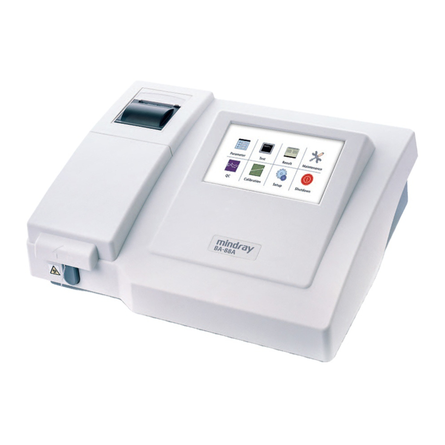
System Description Introduction 1.1.1 Overview The system consists of the analyzer, built-in microprocessor, popup keyboard, internal printer and LCD screen. 1.1.2 Outlook The front view of the semi-auto chemistry analyzer is shown in figure 1-1. - Page 24 Figure 1-1 Front View of the Semi-Auto Chemistry Analyzer The rear view of the semi-auto chemistry analyzer is shown in figure 1-2. Figure 1-2 Rear View of the Semi-Auto Chemistry Analyzer...
-
Page 25: Parameters
USB port is to connect the printer and other external equipments; serial port is to transmit the data after connected to PC. Parameters Light source Tungsten-halogen lamp (6V, 10W) Interferential filter.6 wavelengths (available): 340nm, Filter 405nm, 510nm, 546nm, 578nm 630nm.2 wavelengths (optional): 450nm and 670nm. -
Page 26: Popup Keypad
The ‘click’ operation is used to operate all buttons, options, edit boxes and popup keypad. Drag ‘Drag’ means the act of keeping touching the screen with pen and moving to desired place. The ‘drag’ operation is used to move the scroll bars. 1.3.2 Popup Keypad The popup keypad is used to input numbers, letters and characters. -
Page 27: External Printer
CAUTION Do not use any tools like sandpaper that may damage the thermal components. Do not squeeze the thermal print head. NOTE The paper used for the thermal recorder should be 50mm×20m. 1.4.2 External Printer The external printer is supported by the system. If you want to purchase a printer, please contact our company customer service department or your local distributor. -
Page 29: Installation
Unpacking When you receive the system, carefully inspect the package. If you see any signs of mishandling or damage, file a claim immediately with Mindray customer service department or your local distributor. After opening the package, check the delivered goods against the packing list as well as the appearance of the system. -
Page 30: Space And Accessibility Requirements
Ambient temperature: 15℃-30℃ Relative humidity: 35%-85%, without condensation Above-sea-level height: -400m~3,000 m(70kPa ~ 1,06kPa) Power supply: 100V-240V~ (±10% fluctuation), 50/60Hz (±3Hz fluctuation). The site should be away from the electromagnetic noise and the bearing platform should be free of vibration. The site should not be in direct sun The system should be properly grounded. -
Page 31: Waste Bottle
2.2.5 Waste Bottle A waste bottle should be provided by the user to treat waste liquid, and other suitable ways to dispose the waste liquid are also applicable. NOTE 不 The waste bottle should not be sealed, otherwise the peristaltic pump can not function to aspirate. -
Page 32: Storage For A Short Period
CAUTION Before connecting the power supply, make sure the system is shutdown. Storage for a Short Period When storing the analyzer for a short period, please ensure that the flow cell is filled with clean distilled water or DI water (for instrument with flow cell installed). Storage for Long Period When storing the analyzer for a long period, please ensure that analyzer and accessory in the package be stored:... -
Page 33: Basic Operations
Basic Operations Preparation for Powering On You should perform the following operations before powering on the analyzer. BIOHAZARD Wear gloves and lab coat and, if necessary, goggles when performing the following operations. Check the power supply and make sure it can supply proper voltage for the analyzer. -
Page 34: Timing Principle
Check if the waster tube at the back of the system is connected to the waste bottle or other disposal channels. Check if the waste bottle is full. If yes, empty the waste bottle. NOTE Twisted tubing will make the system incapable of aspiration (for system installed with flow cell). - Page 35 Click Parameter Routine. Basic. Follow the reagent instruction to enter the test parameters concerning reaction type, primary wavelength, secondary wavelength, delay, measuring time, result unit, result precision and reaction temperature, whether to run reagent blank, etc. Refer to 4.2.1.1 Basic for more information.
- Page 36 Endpoint Prepare the samples and calibrators and controls. Prepare proper amount of reagent according the number of the samples. If it is double-reagent analysis, it is recommended that R1 and R2 are mixed and then dispensed into respective tubes (or other reaction containers).
-
Page 37: Cuvette Mode
NOTE Check the reagent instruction, or consult the reagent manufacturer or distributor to see if mixing of R1 and R2 are allowed prior to testing. Click Test on the main screen to enter the test screen. Select the name of the test to be run. Click Water Blank, put the inlet tube into the distilled water, and click Aspirate. -
Page 38: Edit
Figure 3-1 Cover the cuvette cap NOTE: Make sure the cuvette cover and the optical window is closed, during test, otherwise the test result might not be reliable. Edit During test, the online printing is enabled by default and the test result of each sample is printed in real time. -
Page 39: Advanced Operations
Advanced Operations Powering On Power on the analyzer and the system will go through initialization procedure as shown in the following figure. Figure 4-1 Initialization Screen After passing the self-checking, the system will prompt message to aspirate distilled water. Press Aspirate button on the instrument. After aspiration, the main screen will be displayed. -
Page 40: Parameter
If the system failed to pass self-checking, the initialization will be terminated and the main screen will be displayed. Please contact Mindray customer service department or your local distributor for troubleshooting. NOTE If the system failed to pass self-checking, most of the operation including running test will be disabled, except for same inquiry. - Page 41 Figure 4-3 Basic The following table explains the parameters on the Basic screen. Parameter Description Test The test name should be set and same test names are not allowed. The length of the test name should not exceed 10 characters. Otherwise, warning messages will appear.
- Page 42 Parameter Description NOTE The delay is mainly to balance the reaction temperature and eliminate the effect of small bubbles. For Endpoint and Absorbance analysis, the delay is usually set as 6-10 sec. For Fixed-time and Kinetics analysis, it is mainly used to eliminate the effect of unwanted reactions, usually set as 30-60s.
- Page 43 Buttons Function Add new tests. Do not enter a test name already exists. Delete Delete selected test. Save Save the test information. Cancel After selecting a test and setting or modifying parameters for it, click this button to cancel the setting or modification. Return Click this button to return to the main screen.
- Page 44 Parameter Description Reagent blank Absorbance range of the reagent blank. Once this range is absorbance exceeded, error message will appear. The reagent blank absorbance should be entered from low to high. The high and low limit should not be equal. The default is void.
- Page 45 Figure 4-5 Cal Details The following table explains the parameters on the Cal Details screen. Parameter Description K factor For Absorbance analysis, the K factor is fixed at 1 and can not be edited. For Kinetics analysis the K factor is selected by default and you can enter according to the reagent instruction.
- Page 46 4.2.1.4 QC Information The QC Information screen is where you can set the test QC rule and control information. Figure 4-6 QC information The following table explains the parameters on the QC Information screen. Parameter Description Rule Set QC rule for the selected test. One or more rules can be selected, or none is selected.
-
Page 47: Profile
4.2.2 Profile Tests grouped together for certain clinical purposes (for instance liver function) constitute a profile. Figure 4-7 Profile Profile name list is on the left side of the screen, all the on-board test names are listed on the right side of the screen. Select a profile name on the left side and the tests it includes will shown are the list on the left side. - Page 48 Figure 4-8 Calculation The following table explains the parameters on the Calculation screen. Parameter Description Test The test name should be set and same test names are not allowed.. The length of the test name should not exceed 10 characters. Otherwise, warning messages will appear.
- Page 49 Parameter Description Edit Edit the calculation formula. The screen is shown in the following formula figure. How to use the function of the screen to edit formula: the Routine list the tests to be used in the formula. Click Ins to insert these tests into the formula.
-
Page 50: Off-System
4.2.4 Off-system All the tests that are not run by the analyzer are referred to as the off-system tests. You can manually enter the off-system test results in to the system to print out them in the patient report. For newly added off-system test, it is printed after the routine tests. -
Page 51: Test
Buttons Function Cancel After selecting a test and setting or modifying parameters for it, click this button to cancel the setting or modification. Return Click this button to return to the main screen. Test Click Test on the main screen to enter the test screen. The Test screen is divided into three parts: Request, Test and Result. - Page 52 Figure 4-10 Request The following table explains the parameters on the Request screen. Parameter Description Sample ID Sample ID. Range: 001-999. Patient Name of the patient. Tests The names of the on-board tests. Profiles The names of the defined profiles. The following table introduces the buttons on the screen.
- Page 53 Buttons Function View Click this button to check the requesting information of all the samples. Information can be arranged and printed by test or by sample. Return Click this button to return to the main screen. 4.3.2 Test Click Test on the main screen to enter the test screen. Figure 4-11 Test 4-15...
-
Page 54: Test
The following table explains the parameters on the Test screen. Parameter Description Tests A list of all the on-board tests. The requested test is marked with “*”. Parameter View parameters of the selected test. Parameters include: test name, reaction type, wavelength, temperature, delay, measuring time, aspiration volume, blank mode, calibration equation (K factor). - Page 55 Parameter Description Wash Click Wash. The system will aspirate certain amount of distilled water to wash the tubing. Stop Stop testing or washing. The sample ID will not increase automatically. Water Blank Run DI water zero. Rgt. Blank Run reagent blank for the selected test. Sample Blank Run Sample Blank for the selected sample.
- Page 56 Parameter Description Conc. Result concentration. While running calibration, this area will show the set point of the calibrator. Realtime During test, this area shows the real-time ABS. When test is completed, this area shows the response of the current sample. Rgt.
-
Page 57: Calibration
Figure 4-12 Test workflow Select test Water blank Reagent blank Calibrator Sample blank Control (Sample) Next sample (QC)? NOTE During test, if the cuvettes are contaminated, the test result might not be reliable. We recommend you to wash the cuvette using ethanol solution (the volume ratio of ethanol and water is 4:1) or wash solutions specific for cuvette. - Page 58 Figure 4-13 Calibration The following table explains the parameters on the Calibration Details. Parameter Description Test Test that has been calibrated. Date The date when calibration of the test is run. Rule Calibration rule. 4-20...
- Page 59 The following explains the Calibrator and Parameter. Parameter Description Calibrator No. The range is S1-S8. Std. Conc. Set point of the calibrator. Response Response of the calibrator. Parameter Parameters in the calibration formula. Value Value of the parameters in the calibration formula. The following introduces the buttons on the screen.
- Page 60 Buttons Function Print Print current calibration parameters and curve. Return Click this button to return to the main screen. CAUTION The replacement of certain components should be followed with calibration. Otherwise, you may get unreliable result. You can view the QC result and QC reaction curve, and check whether the test is out of control and print QC reaction curve in the QC screen.
-
Page 61: Result
Parameter Description C1, C2, C3 A tab used to switch between C1, C2 and C3 to view the QC data. No. of the QC result. Date Date when the QC is run. Concentration QC result Remark Display “in control” or “out of control” according the QC result and QC rule. - Page 62 4.6.1 Result 4.6.1.1 View Results by Sample Figure 4-15 View Results by Sample Select Sample to display the result by sample; select Test to display the result by test. The result of the current day will be displayed by default. It there is no test result for the current day.
- Page 63 Buttons Function Query Click Query to pop up the following page. Select data range or patient name or/and Sample ID to search for results that meet the requirement. Add new patient information. Edit Select one sample to a sample result to enter the Edit page or enter the page directly.
- Page 64 4.6.1.2 View Results by Test Figure 4-16 View Results by Test Refer to the above for parameter on Test screen. The following table introduces the buttons on the Test screen. Buttons Function Query Click Query to pop up the following page. Select data range or patient name or/and Sample ID to search for results that meet the requirement.
-
Page 65: Edit
Buttons Function Summary Click Summary to pop up the following page. Select Test (including all the on-board tests and defined off-system tests) and time range to search for results that meet the requirement. Print Print the report of the selected sample. Return Click this button to return to the main screen. - Page 66 Figure 4-17 Test report 4.6.2.1 Test Result Figure 4-18 Test result The following table explains the parameters on the screen. Parameter Description Test Name of the test. Conc. Test result. Unit Unit of the test result. Reference Reference range of the test. Response Response of the test.
- Page 67 The following introduces the buttons on the screen. Buttons Function Click Add to pop up the following screen. Select the test name (including routine test and calculation test in the Routine drop-down list box. Enter the Quantitative and/or flag result in the Result area. Select test name for off-system test, enter the test result in Result area.
-
Page 68: Setup
Parameter Description Sample ID Sample ID of the patient. If you enter the screen by selecting a test result, the sample ID can not be edited. The sample ID should not be void. Otherwise, the patient information can not be saved. The entered sample ID can not be the same with the existing sample ID of the current day. -
Page 69: Basic
4.7.1 Basic Figure 4-19 Basic setup of the system information The following table explains the parameters on the Basic screen. Parameter Description FPGA The version information of the system. Software Hospital Name of the hospital. Start button Start the function of making sound when pressing a button. sound Pump 3 pump speeds are available: 1, 2, 3. -
Page 70: Dictionary
NOTE Sound alarming is available on the system. If the sound of pressing a button is shut off, the sound alarming function will be disabled, then you should observe the prompt information for any alarming. The following table introduces the button on the screen. Buttons Function Touchscr. -
Page 71: Print Features
Figure 4-20 Dictionary The following table explains the parameters on the Dictionary screen. Parameter Description Unit Add, delete test unit. Type Add, delete sample type. Sender Add, delete the name of the doctor who sends the sample. Tester Add, delete the name of the doctor who tests the sample. Reviewer Add, delete the name of the doctor who reviews the sample result. -
Page 72: Carryover
Figure 4-21 Print Features The following table explains the parameters on the Print Features screen. Parameter Description Internal Select internal thermal recorder to print test result. Printer External Select external printer to print test result. The Appendix lists the Printer printers the system supports. -
Page 73: Lis Setup
Figure 4-22 Carryover Select contaminating test in the Contaminating test list; select contaminated test in the Contaminated test list. Select Save to save the setting. 4.7.5 LIS Setup You can send the test result to LIS, after some parameters have been set is LIS setup. -
Page 74: Maintenance
When the system is connected with data management software, In Instrument reg.—Channel No. setup, the channel No. of fields like test information, sample type should be consistent with System—LIS setup in BA-88A, otherwise, the information can not be uploaded correctly. -
Page 75: Log
Figure 4-24 Database 4.8.2 Log You can view failure records on this screen. Figure 4-25 Log Error list is on the left side of the Log screen. On the right side of the screen, detailed information about the selected item is shown, including Error Info., Causes and Corrective, which can be used as reference while troubleshooting the failures. -
Page 76: Maintenance
4.8.3 Maintenance In this screen, you can conduct maintenance by selecting Pump cal and Gain adjust. The Password function is only available to service personnel and authorized distributors. Figure 4-26 Maintenance 4.8.3.1 Pump Calibration Figure 4-27 Pump calibration Pump Cal can facilitate the calibration of peristaltic pump. The detailed procedures are as follows: Prepare 6000µl distilled water, select 1 , and then click Start. -
Page 77: Shutdown
system will start to aspirate distilled water. When all the water has been aspirated, click Stop. Follow the procedure above to finish the 2 and 3 calibration. NOTE The error of the volume 6000 µl should be as small as possible. As soon as all the distilled water is aspirated, the Stop should be clicked, otherwise the calibration might not be precise. -
Page 79: Maintenance
Maintenance To ensure good performance of the system, regular maintenance is required. WARNING Do not perform any maintenance procedures that are not described in this chapter. Otherwise, it may lead to personnel injury or equipment damage. Do not touch the parts other than specified. Performing unauthorized maintenance procedures may damage your system, void any applicable warranty or service contract and even cause personal injury. -
Page 80: Weekly Maintenance
3、 When the system is not in use, make sure that the tubing and the flow cell is filled with clean distilled water (or DI water). Weekly Maintenance 1、 Wash the waste bottle interior with clean water. Soak the bottle with disinfector if necessary. -
Page 81: Adjusting The Photoelectric Gain
WARNING Some reagents are corrosive. Exercise caution when handling the reagents. In case the reagents or wash solution spill into your eyes, rinse them with much water and consult an oculist. 5.3.2 Adjusting the Photoelectric Gain When the alarm message “Light signal too weak” or “Light signal too strong” appears, please check whether there is air in cuvette or whether the cuvette is placed right. - Page 82 Locate the position where the peristaltic pump is installed. Pull out the tubing that goes through the backboard of the analyzer for 40-50mm until the adapter is exposed. Pinch the two buckles on the left and right side of the pump shell and detach the pump head carefully.
- Page 83 After unplugging the adapters, pinch the buckles on the pump head and detach the pump shell. Pinch buckles pump head detach pump shell. After detaching the pump shell, press the roller inside the pump to take the used pump tubing out. Remove the red ring on the used tubing and install them on the new tubing.
- Page 84 After mounting the pump shell, install the pump head on the pump. Install the pump head on the pump, with motor shaft into installation hole Pinch buckles to lock the pump head After installing the pump head, connect the tubing with the tubing that goes through the backboard and the waste tubing.
-
Page 85: Replacing Aspiration Tubing
NOTE The service life of the pump tubing is 18 month. Tubing should be checked irregularly and replaced in time. Do not use excessive force while pulling, slipping the tubing or doing any operation that might pulling the tubing. Otherwise, the tubing might be damaged or the inner connection might be cut off. -
Page 86: Replacing Lamp
Connect the thicker end of the new tube to the inlet metal tube and then guide the tube through the deflection tube. thicker connected with the metal tube Aspiration deflection tube BIOHAZARD When replacing the pump tubing, wear gloves and lab coat and, if necessary, goggles. - Page 87 Open the optical window cover, use cross screw driver to unscrew the screws on the lamp replacement window cover. Remove the cover. Unscrew screws remove replacement window cover Unscrew the fastening screw of the lamp base (if it is difficult to dismount, some tools like the clipper might be used).
- Page 88 Pull the wire out and you can see the wire joint connecting the lamp assembly, with one end connecting to the lamp and the other end connecting to the inside of the instrument. Pinch both ends of the joint and press the buckle to disconnect the joint.
-
Page 89: Calculating Calibration Parameters And Qc Rule
Calculating Calibration Parameters and QC Rule The system provides two calibration methods: linear calibration and nonlinear calibration. Linear calibration includes one-point linear calibration, two-point linear calibration and multi-point linear calibration. They are mainly used for tests determined by colorimetry. Nonlinear calibration includes Logit-Log 4P, Logit-Log 5P, Exponential 5P, Polynomial 5P, Parabola and Spline. -
Page 90: Calculating Nonlinear Calibration Parameters
This calibration method requires only one calibrator. Two-point linear calibration Calibration formula: This calibration method adopts two calibration parameters: , where, − − − ( ) − − This calibration method requires two calibrators. are respectively the concentrations of calibrator 1 and calibrator 2. are respectively the responses of calibrator 1 and calibrator 2. - Page 91 Figure 6-1 Logit-Log 4P calibration curve Logistic-Log 5P Calibration formula: − exp[ This calibration method adopts five parameters: This calibration method requires at least five calibrators. The concentration (or activity) of calibrator 1 is 0, and the corresponding is equal to applications of the calibration method are the same with that of Logit-Log 4P, but this method has a higher fitting.
-
Page 92: Calculating Concentration
This calibration method adopts five parameters: This calibration method requires at least five calibrators. The concentration (or activity) of calibrator 1 is 0, and the corresponding is equal to Parabola Calibration formula: This calibration method adopts three parameters: This calibration method requires at least three calibrators. The calibration parameters can be calculated through the method of polynomial least squares. -
Page 93: Calculating Concentration Of Nonlinearly Calibrated Sample/Control
Multi-point linear calibration − Where, - calibration parameters 6.3.2 Calculating Concentration of Nonlinearly Calibrated Sample/control Logistic-Log 4P − − − − Where, - calibration parameters Logistic-Log 5P The positive real root is obtained with the dichotomy method. Exponential5P The positive real root is obtained with the dichotomy method. Polynomial5P −... -
Page 94: Qc Rule
Spline Spline defines several calculation sections based on the responses of calibration concentrations. Each section differs in specific parameters. Therefore, the section to which the current response belongs should be confirmed before Spline calculation. The parameters of relevant section shall be used to obtain a positive real root with the dichotomy method. - Page 95 Figure 6-3 Westgard Multi-rule QC Conclusion Flow For several controls, the conclusion logic is similar to the above condition, except for multiple continuous QC data, which should be combined simultaneously.
-
Page 97: Appendix A Specifications
Appendix A Specifications Technical Specifications Test principle: Colorimetry, Turbidity Analytical methods: Endpoint, Fixed-time, Kinetic and Absorbance. All of the four methods support double wavelength Sample volume: 200μl~9000μl Light source: tungsten-halogen lamp 6V, 10W. Wavelength: 340nm, 405nm, 510nm, 546nm, 578nm, 630nm. Optional: 450nm, 670nm. - Page 98 Input/Output Devices Touchscreen Popup keyboard Recorder Interface RS-232: interface between the analyzer and the PC. USB port: interface between the analyzer and the mouse, keyboard or portable storage device. Safety Classification Electric shock protection I type equipment powered by external equipment. Overvoltage type: II Pollution level: 2 Device type: fixed device...
-
Page 99: Appendix B Error Messages
Not enough paper in the printer Check whether there is enough print or printer damaged paper. Restart the system. If the alarm continues contact Mindray customer service department or your local distributor. Absorbance Absorbance exceeds the limit Check for impurity in the sample;... - Page 100 Lamp is not turned on, or light Restart the system or refer to the weak source degenerated, or light 5.3.2. If the alarm continues path is obstructed, or lamp falls contact Mindray customer service off, or gain error occurs department your local distributor. Dark current is AD collection error or circuit Restart the system.
- Page 101 Can not pass hardware If it happens in two consecutive Circuit error self-check times, contact the developer. Light signal too Photoelectric gain adjusting Restart the system. If the alarm strong error continues contact Mindray customer service department or your local distributor.
- Page 103 Appendix C External Printer The system is compatible with (not limited to) the following printers: HP DeskJet 5652 HP DeskJet 3820 HP DeskJet 5438 HP DeskJet 3668 HP DeskJet D2368 HP Photosmart D5168 HP Business InkJet 1000...
- Page 105 Appendix D Supplies To ensure personal safety and system performance, use only supplies manufactured or recommended by our company. Contact our customer service department or your local distributor for details. Part Name Part Number Location Description Lamp assembly BA89-30-86998 Lamp base Regularly-replace d part Flow cell...
- Page 107 P/N: BA89-20-87038(1.0)
Need help?
Do you have a question about the BA-88A and is the answer not in the manual?
Questions and answers
Неча вольт
The voltage specification for the Mindray BA-88A is:
Input:
- Input power: 140 VA
- Input AC voltage: 100–240V~
- Frequency: 50/60 Hz ±3 Hz
Output:
- A5V for circuit board
- A12V and -12V for analogue circuit board
- 24V for board motor/power driver
- B12V for recorder, fan, peristaltic pump motor, semiconductor heater, and power driver
- 9.9V for LCD background light
- B5V for lamp power supply
This answer is automatically generated
Les résultats pour les tests de diabète sont incorrect
Common issues with incorrect diabetes test results on the Mindray BA-88A include interference from carbamylated hemoglobin (CarHb), which can falsely elevate HbA1c results when using ion-exchange HPLC. CarHb has a similar charge to HbA1c and can overlap its peak during analysis. Additionally, system errors such as abnormal temperature, faulty sensors, blocked fan, or damaged filter wheel may prevent the test from running properly. These errors are displayed via dialog boxes and sound alarms, and are logged with details for troubleshooting.
This answer is automatically generated
How to change language
To change the language on the Mindray BA-88A, continuously click the Ctrl button twice to switch between English and Chinese.
This answer is automatically generated
WHAT DOES IT MEAN WHEN THE MACHINE SAYS COMMUNICATION ERROR
A communication error on the Mindray BA-88A machine indicates that there is an issue with the connection between the CPU board and the CPU extension board, or between the MCU and FPGA. This can be caused by a loose connection, a faulty CPU board, or a failed FPGA. In such cases, the affected component should be checked and replaced if necessary.
This answer is automatically generated