
Related Manuals for Omron Q2V Series


Summary of Contents for Omron Q2V Series
- Page 1 Driving Quality Technical Manual Item code: Q2V-Axxxx-xxx 200 V Class, Three-Phase: 0.1 to 22 kW 200 V Class, Single-Phase: 0.1 to 4.0 kW 400 V Class, Three-Phase: 0.37 to 30 kW...
- Page 2 This Page Intentionally Blank SIEPCYEUOQ2V01A Q2V Technical Manual...
-
Page 3: Table Of Contents
Table of Contents i. Preface and General Precautions ....... . . 13 Safety Information . - Page 4 Control Circuit Wiring..........74 Control Circuit Connection Diagram .
- Page 5 How to Switch between LOCAL and REMOTE ........111 Start-up Procedures .
- Page 6 Safe Disable Input ..........180 Safe Disable Specifications .
- Page 7 Motor Rotation Causes Oscillation or Hunting ........263 PID Output Fault.
- Page 8 11.4 b: APPLICATION ........... 318 b1: OPERATION MODE SELECT.
- Page 9 n8: PM MOTOR CONTROL TUNING ......... 377 nA: PM MOTOR CONTROL TUNING.
- Page 10 C2: JERK CONTROL............493 C3: SLIP COMPENSATION .
- Page 11 12.11 T: AUTOTUNING ........... 715 T0: TUNE MODE .
- Page 12 SIEPCYEUOQ2V01A Q2V Technical Manual...
-
Page 13: Preface And General Precautions
Preface and General Precautions This chapter gives information about important safety precautions for the use of this product. Failure to obey these precautions can cause serious injury or death, or damage to the product or related devices and systems. Safety Information....................14 Legal Information ..................... -
Page 14: Safety Information
i.1 Safety Information Safety Information Read and understand this manual before you install, operate, or do maintenance on the drive. Install the drive as specified by this manual and local codes. The symbol marks in this section identify safety messages in this manual. Failure to obey these safety messages can cause serious injury, death, or damage to the products and related equipment and systems. - Page 15 i.1 Safety Information WARNING Crush Hazard Test the system to make sure that the drive operates safely after you wire the drive and set parameters. If you do not test the system, it can cause damage to equipment or serious injury or death. Sudden Movement Hazard Before you do a test run, make sure that the setting values for virtual input and output function parameters are correct.
-
Page 16: Warning Label Content And Location
i.1 Safety Information NOTICE Use an inverter-duty motor or vector-duty motor with reinforced insulation and windings applicable for use with an AC drive. If the motor does not have the correct insulation, it can cause a short circuit or ground fault from insulation deterioration. -
Page 17: Legal Information
i.2 Legal Information Legal Information ◆ Exclusion of Liability • This product is not designed and manufactured for use in life-support machines or systems. • Contact your sales representative if you are considering the application of this product for special purposes, such as machines or systems used for passenger cars, medicine, airplanes and aerospace, nuclear power, electric power, or undersea relaying. - Page 18 i.2 Legal Information SIEPCYEUOQ2V01A Q2V Technical Manual...
-
Page 19: Receiving
Receiving This chapter gives information about the different drive models and features, and how to examine the drive when you receive it. Model Number and Nameplate Check..............20 Features and Advantages of Control Methods..........23 SIEPCYEUOQ2V01A Q2V Technical Manual... -
Page 20: Model Number And Nameplate Check
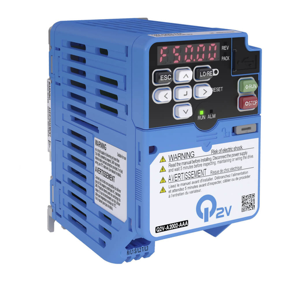
1.1 Model Number and Nameplate Check Model Number and Nameplate Check Please examine these items after you receive the drive: • Examine the drive for damage. Immediately contact the shipping company if the drive is damaged. The warranty does not cover damage from shipping. •... - Page 21 1.1 Model Number and Nameplate Check Description A: IP20 protection Class Input power supply voltage • B: Single-Phase AC 200 V Class • 2: Three-Phase AC 200 V Class • 4: Three-Phase AC 400 V Class Rated output current Note: Refer to the rated output current list for more information.
- Page 22 1.1 Model Number and Nameplate Check Table 1.3 Single-Phase AC 200 V Class HD Rating ND Rating [C6-01 = 0] [C6-01 = 1] (Default) Model Maximum Applicable Motor Maximum Applicable Motor Rated output current Rated output current Output Output B001 0.18 B002 0.25...
-
Page 23: Features And Advantages Of Control Methods
1.2 Features and Advantages of Control Methods Features and Advantages of Control Methods This drive has 5 available control methods from which you can select for different applications. Table 1.5 Features and Advantages of V/f Control Open Loop V/f Control Control Method Selection Notes V/f Control) - Page 24 1.2 Features and Advantages of Control Methods Open Loop Vector Control Method Selection Notes (OLVector) Controlled Motor Induction Motor Auto-Tuning Rotational, Stationary, and Line-to-Line Resistance Automatically tunes electrical motor parameters. Controls maximum motor torque to prevent damage to machines and Torque Limits loads.
- Page 25 1.2 Features and Advantages of Control Methods PM Open Loop Vector PM Advanced Open Loop EZ Open Loop Vector Control Control Method Control Vector Notes Selection (EZ Vector) (PM OLVector) (PM AOLVector) Induction Motors/PM Motors/ Controlled Motor PM Motor SynRM (Synchronous Reluctance Motors) Immediately estimates (or detects) motor Yes (Although NOT operation in...
- Page 26 1.2 Features and Advantages of Control Methods SIEPCYEUOQ2V01A Q2V Technical Manual...
-
Page 27: Mechanical Installation
Mechanical Installation This chapter gives information about the correct environment or space to install the drive. Safety Precautions....................28 Installation Environment ..................29 Installation Position and Distance ............... 30 Moving the Drive....................... 32 Removing/Reattaching Covers................33 Remove and Reattach the Keypad............... 35 Install the Keypad to a Control Panel or Another Device....... -
Page 28: Safety Precautions
2.1 Safety Precautions Safety Precautions WARNING Electrical Shock Hazard Only let approved personnel install, wire, maintain, examine, replace parts, and repair the drive. If personnel are not approved, it can cause serious injury or death. Do not modify the drive body or drive circuitry. Modifications to drive body and circuitry can cause serious injury or death, will cause damage to the drive, and will void the warranty. -
Page 29: Installation Environment
2.2 Installation Environment Installation Environment The installation environment is important for the lifespan of the product and to make sure that the drive performance is correct. Make sure that the installation environment agrees with these specifications. Conditions Environment Indoors Area of Use Overvoltage Category III (IEC60664) Power Supply IP20/UL Open Type: -10 °C to +50 °C (14 °F to 122 °F) -
Page 30: Installation Position And Distance
2.3 Installation Position and Distance Installation Position and Distance Install the drive vertically for sufficient airflow to cool the drive. A - Vertical installation C - Rotated installation B - Horizontal installation Figure 2.1 Installation Orientation ◆ Single Drive Installation Use the clearances specified to install the drive. - Page 31 2.3 Installation Position and Distance A - 50 mm (1.97 in) minimum C - 100 mm (3.94 in) minimum above between upper and lower and below openings B - 30 mm (1.18 in) minimum on each side Figure 2.3 Installation Distances for More than One Drive (Side-by-Side) Note: When you replace the cooling fans, align the tops of drives that have different dimensions.
-
Page 32: Moving The Drive
2.4 Moving the Drive Moving the Drive Obey local laws and regulations when moving and installing this product. CAUTION! Sudden Movement Hazard. Do not hold the drive by the keypad or front cover. Tighten the screws correctly before moving the drive. Failure to obey can cause minor to moderate injury. SIEPCYEUOQ2V01A Q2V Technical Manual... -
Page 33: Removing/Reattaching Covers
2.5 Removing/Reattaching Covers Removing/Reattaching Covers DANGER! Electrical Shock Hazard. Do not examine, connect, or disconnect wiring on an energized drive. Before servicing, disconnect all power to the equipment and wait for the time specified on the warning label at a minimum. The internal capacitor stays charged after the drive is de-energized. - Page 34 2.5 Removing/Reattaching Covers Use a slotted screwdriver to lock the front cover of the drive. Use a slotted screwdriver with a tip width of 2.5 mm (0.1 in) or less and a thickness of 0.4 mm (0.02 in) or less. A - Front Cover Lock Figure 2.7 Locking the Front Cover SIEPCYEUOQ2V01A Q2V Technical Manual...
-
Page 35: Remove And Reattach The Keypad
2.6 Remove and Reattach the Keypad Remove and Reattach the Keypad ◆ Remove the Keypad Remove the front cover. Push on the tab on the right side of the keypad, then pull the keypad forward to remove it from the drive. Figure 2.8 Remove the Keypad ◆... -
Page 36: Install The Keypad To A Control Panel Or Another Device
2.7 Install the Keypad to a Control Panel or Another Device Install the Keypad to a Control Panel or Another Device You can remove the keypad from the drive and connect it to a remote control extension cable to make operation easier when you cannot access the drive. -
Page 37: Installation Methods
2.8 Installation Methods Installation Methods The drive installation methods include standard installation and external heatsink installation. ◆ Standard Installation Refer to Drive Exterior and Mounting Dimensions on page 307 for more information about external dimensions. ◆ External Heatsink The optional External Heatsink Installation Kit will let you install the drive with the heatsink external to the enclosure panel. - Page 38 2.8 Installation Methods SIEPCYEUOQ2V01A Q2V Technical Manual...
-
Page 39: Electrical Installation
Electrical Installation This chapter gives how to wire the control circuit terminals, motor, and power supply of the drive. Safety Precautions....................40 Standard Connection Diagram ................42 Main Circuit Wiring ....................45 Main Circuit Terminal Block Wiring Procedure ..........71 Control Circuit Wiring ..................... -
Page 40: Safety Precautions
3.1 Safety Precautions Safety Precautions DANGER Electrical Shock Hazard Do not examine, connect, or disconnect wiring on an energized drive. Before servicing, disconnect all power to the equipment and wait for the time specified on the warning label at a minimum. - Page 41 3.1 Safety Precautions WARNING Do not use the main circuit power supply (Overvoltage Category III) at incorrect voltages. Operate the drive in the specification range of the input voltage on the drive nameplate. Voltages that are higher than the permitted nameplate tolerance can cause damage to the drive. When you install a dynamic braking option, wire the components as specified by the wiring diagrams.
-
Page 42: Standard Connection Diagram
3.2 Standard Connection Diagram Standard Connection Diagram Wire the drive as specified by Figure 3.1. WARNING! Sudden Movement Hazard. Set the MFDI parameters before you close control circuit switches. Incorrect Run/Stop circuit sequence settings can cause serious injury or death from moving equipment. WARNING! Sudden Movement Hazard. - Page 43 3.2 Standard Connection Diagram Figure 3.1 Standard Drive Connection Diagram Set the wiring sequence to de-energize the drive with the MFDO. If the drive outputs a fault during fault restart when you use the fault restart function, set L5-02 = 2 [Fault@Reset Select = Enable Fault Output] to de-energize the drive. Be careful when you use a cut-off sequence.
- Page 44 3.2 Standard Connection Diagram When you use a regenerative converter or regenerative unit, set L8-55 = 0 [DB IGBT Protection = Disable]. If L8-55 = 1 [Enabled], the drive will detect rF [Braking Resistor Fault]. When you use a regenerative converter, regenerative unit, braking resistor, or braking resistor unit, set L3-04 = 0 [StallP@Decel Enable = Disabled].
-
Page 45: Main Circuit Wiring
3.3 Main Circuit Wiring Main Circuit Wiring This section gives information about the functions, specifications, and procedures necessary to safely and correctly wire the main circuit in the drive. NOTICE: The drive can fail if users frequently turn the drive ON and OFF with the MC on the power source side to Run and Stop the drive. -
Page 46: Configuration Of Main Circuit Terminal Block
3.3 Main Circuit Wiring ◆ Configuration of Main Circuit Terminal Block ■ Models B001 - B004 Figure 3.3 Single-Phase, With a Built-in EMC Filter ■ Models B006 - B010 Figure 3.4 Single-Phase, With a Built-in EMC Filter ■ Model B012 Figure 3.5 Single-Phase, With a Built-in EMC Filter SIEPCYEUOQ2V01A Q2V Technical Manual... - Page 47 3.3 Main Circuit Wiring ■ Model B018 Figure 3.6 Single-Phase, Without a Built-in EMC Filter ■ Models 2001 - 2006 Figure 3.7 Three-Phase, With a Built-in EMC Filter ■ Models 2008 - 2012, 4001 - 4009 Figure 3.8 Three-Phase, With a Built-in EMC Filter SIEPCYEUOQ2V01A Q2V Technical Manual...
- Page 48 3.3 Main Circuit Wiring ■ Model 2018 - 2021, 4012 Figure 3.9 Three-Phase, With a Built-in EMC Filter ■ Models 2030 - 2042, 4018 - 4023 Figure 3.10 Three-Phase, With a Built-in EMC Filter SIEPCYEUOQ2V01A Q2V Technical Manual...
- Page 49 3.3 Main Circuit Wiring ■ Models 2056, 4031 - 4038 Figure 3.11 Three-Phase, With a Built-in EMC Filter ■ Models 2070, 2082 Figure 3.12 Three-Phase, With a Built-in EMC Filter SIEPCYEUOQ2V01A Q2V Technical Manual...
-
Page 50: Main Circuit Terminal Functions
3.3 Main Circuit Wiring ■ Models 4044, 4060 Figure 3.13 Three-Phase, With a Built-in EMC Filter ◆ Main Circuit Terminal Functions Table 3.1 Main Circuit Terminal Names and Functions Models 2001 - 2082 Terminal Models B001 - B018 Function Models 4001 - 4060 R/L1 S/L2 Main circuit power supply input... - Page 51 3.3 Main Circuit Wiring Table 3.2 Icons to Identify Screw Shapes Icon Screw Shape Slotted (-) Hex socket cap (WAF: 5 mm) ■ Wire Selection Precautions WARNING! Electrical Shock Hazard. Make sure that the protective ground wire conforms to technical standards and local safety regulations.
- Page 52 3.3 Main Circuit Wiring Three-Phase 200 V Class (CE-compliance) Wire Stripping Recommended Gauge Applicable Gauge Tightening Torque Length Model Terminal Terminal Screw N∙m (in∙lb) 0.5 - 0.6 R/L1, S/L2, T/L3 (4.4 - 5.3) 0.5 - 0.6 U/T1, V/T2, W/T3 (4.4 - 5.3) 0.5 - 0.6 2001 -, +1, +2...
- Page 53 3.3 Main Circuit Wiring Wire Stripping Recommended Gauge Applicable Gauge Tightening Torque Length Model Terminal Terminal Screw N∙m (in∙lb) 0.5 - 0.6 R/L1, S/L2, T/L3 2.5 - 4 (4.4 - 5.3) 0.5 - 0.6 U/T1, V/T2, W/T3 2.5 - 4 (4.4 - 5.3) 0.5 - 0.6 2010...
- Page 54 3.3 Main Circuit Wiring Wire Stripping Recommended Gauge Applicable Gauge Tightening Torque Length Model Terminal Terminal Screw N∙m (in∙lb) 1.5 - 1.7 R/L1, S/L2, T/L3 2.5 - 16 (13.5 - 15) 1.5 - 1.7 U/T1, V/T2, W/T3 2.5 - 16 (13.5 - 15) 2.3 - 2.5 2042...
- Page 55 3.3 Main Circuit Wiring Single-Phase 200 V Class (CE-compliance) Wire Stripping Recommended Gauge Applicable Gauge Tightening Torque Length Model Terminal Terminal Screw N∙m (in∙lb) 0.5 - 0.6 L/L1, N/L2 (4.4 - 5.3) 0.5 - 0.6 U/T1, V/T2, W/T3 (4.4 - 5.3) 0.5 - 0.6 B001 -, +1...
- Page 56 3.3 Main Circuit Wiring Wire Stripping Recommended Gauge Applicable Gauge Tightening Torque Length Model Terminal Terminal Screw N∙m (in∙lb) 1.5 - 1.7 L/L1, N/L2 2.5 - 6 (13.5 - 15) 1.5 - 1.7 U/T1, V/T2, W/T3 2.5 - 4 (13.5 - 15) 1.5 - 1.7 B012 -, +1...
- Page 57 3.3 Main Circuit Wiring Wire Stripping Recommended Gauge Applicable Gauge Tightening Torque Length Model Terminal Terminal Screw N∙m (in∙lb) 0.5 - 0.6 R/L1, S/L2, T/L3 2.5 - 4 (4.4 - 5.3) 0.5 - 0.6 U/T1, V/T2, W/T3 2.5 - 4 (4.4 - 5.3) 0.5 - 0.6 4004...
- Page 58 3.3 Main Circuit Wiring Wire Stripping Recommended Gauge Applicable Gauge Tightening Torque Length Model Terminal Terminal Screw N∙m (in∙lb) 1.5 - 1.7 R/L1, S/L2, T/L3 2.5 - 4 (13.5 - 15) 1.5 - 1.7 U/T1, V/T2, W/T3 2.5 - 4 (13.5 - 15) 1.5 - 1.7 4018...
- Page 59 3.3 Main Circuit Wiring Wire Stripping Recommended Gauge Applicable Gauge Tightening Torque Length Model Terminal Terminal Screw N∙m (in∙lb) • ≤ 25 mm 2.3 - 2.5 (19.8 - 22) R/L1, S/L2, T/L3 6 - 35 • 35 mm ≤ 4.1 - 4.5 (36 - 40) 2.3 - 2.5 U/T1, V/T2, W/T3...
- Page 60 3.3 Main Circuit Wiring Three-Phase 200 V Class (UL-compliance) Wire Terminal Screw Recommended Applicable Gauge Stripping Tightening Torque Gauge Model Terminal Length N∙m (in∙lb) Size Shape 0.5 - 0.6 R/L1, S/L2, T/L3 (4.4 - 5.3) 0.5 - 0.6 U/T1, V/T2, W/T3 (4.4 - 5.3) 0.5 - 0.6 2001...
- Page 61 3.3 Main Circuit Wiring Wire Terminal Screw Recommended Applicable Gauge Stripping Tightening Torque Gauge Model Terminal Length N∙m (in∙lb) Size Shape 0.5 - 0.6 R/L1, S/L2, T/L3 2 - 3.5 (4.4 - 5.3) 0.5 - 0.6 U/T1, V/T2, W/T3 2 - 3.5 (4.4 - 5.3) 0.5 - 0.6 2010...
- Page 62 3.3 Main Circuit Wiring Wire Terminal Screw Recommended Applicable Gauge Stripping Tightening Torque Gauge Model Terminal Length N∙m (in∙lb) Size Shape 1.5 - 1.7 R/L1, S/L2, T/L3 3.5 - 14 (13.5 - 15) 1.5 - 1.7 U/T1, V/T2, W/T3 3.5 - 14 (13.5 - 15) •...
- Page 63 3.3 Main Circuit Wiring Single-Phase 200 V Class (UL-compliance) Wire Terminal Screw Recommended Applicable Gauge Stripping Tightening Torque Gauge Model Terminal Length N∙m (in∙lb) Size Shape 0.5 - 0.6 L/L1, N/L2 (4.4 - 5.3) 0.5 - 0.6 U/T1, V/T2, W/T3 (4.4 - 5.3) 0.5 - 0.6 B001...
- Page 64 3.3 Main Circuit Wiring Wire Terminal Screw Recommended Applicable Gauge Stripping Tightening Torque Gauge Model Terminal Length N∙m (in∙lb) Size Shape 1.5 - 1.7 L/L1, N/L2 3.5 - 8 (13.5 - 15) 1.5 - 1.7 U/T1, V/T2, W/T3 2 - 3.5 (13.5 - 15) 1.5 - 1.7 B012...
- Page 65 3.3 Main Circuit Wiring Wire Terminal Screw Recommended Applicable Gauge Stripping Tightening Torque Gauge Model Terminal Length N∙m (in∙lb) Size Shape 0.5 - 0.6 R/L1, S/L2, T/L3 2 - 3.5 (4.4 - 5.3) 0.5 - 0.6 U/T1, V/T2, W/T3 2 - 3.5 (4.4 - 5.3) 0.5 - 0.6 4004...
- Page 66 3.3 Main Circuit Wiring Wire Terminal Screw Recommended Applicable Gauge Stripping Tightening Torque Gauge Model Terminal Length N∙m (in∙lb) Size Shape 1.5 - 1.7 R/L1, S/L2, T/L3 2 - 5.5 (13.5 - 15) 1.5 - 1.7 U/T1, V/T2, W/T3 2 - 5.5 (13.5 - 15) 1.5 - 1.7 4018...
-
Page 67: Main Circuit Terminal And Motor Wiring
3.3 Main Circuit Wiring Wire Terminal Screw Recommended Applicable Gauge Stripping Tightening Torque Gauge Model Terminal Length N∙m (in∙lb) Size Shape • ≤ 22 mm 2.3 - 2.5 (19.8 - 22) R/L1, S/L2, T/L3 5.5 - 30 • 30 mm ≤... - Page 68 3.3 Main Circuit Wiring WARNING! Electrical Shock Hazard. Make sure that the protective ground wire conforms to technical standards and local safety regulations. The IEC/EN 61800-5-1:2007 standard specifies that you must wire the power supply to automatically de- energize when the protective ground wire disconnects. If you turn on the internal EMC filter, the leakage current of the drive will be more than 3.5 mA.
- Page 69 3.3 Main Circuit Wiring Models 2001 - 2004, 4001 - 4004 Models 2006 - 2082, 4005 - 4060 Models B001 - B004 SIEPCYEUOQ2V01A Q2V Technical Manual...
- Page 70 3.3 Main Circuit Wiring Models B006 - B012 SIEPCYEUOQ2V01A Q2V Technical Manual...
-
Page 71: Main Circuit Terminal Block Wiring Procedure
3.4 Main Circuit Terminal Block Wiring Procedure Main Circuit Terminal Block Wiring Procedure DANGER! Electrical Shock Hazard. Do not examine, connect, or disconnect wiring on an energized drive. Before servicing, disconnect all power to the equipment and wait for the time specified on the warning label at a minimum. The internal capacitor stays charged after the drive is de-energized. -
Page 72: 3.4 Main Circuit Terminal Block Wiring Procedure
3.4 Main Circuit Terminal Block Wiring Procedure A - Cable clamp Figure 3.17 Strain Relief Example Table 3.4 Recommended Wiring Tools Bit Model Torque Driver Model Torque Wrench Screw Screw Shape Wire Gauge Adapter Size (Manufacturer) (Tightening Torque) (Tightening Torque) TSD-M 1,2NM SF-BIT-SL 0,5X3,0-70 (0.3 - 1.2 N∙m... - Page 73 3.4 Main Circuit Terminal Block Wiring Procedure Tighten the screws to the specified torque. Figure 3.19 Tighten Terminal Block Screws If you removed IP20 protection covers, install them into their initial positions. SIEPCYEUOQ2V01A Q2V Technical Manual...
-
Page 74: Control Circuit Wiring
3.5 Control Circuit Wiring Control Circuit Wiring ◆ Control Circuit Connection Diagram Wire the drive control circuit as shown. Figure 3.20 Control Circuit Connection Diagram Connect a 24 V power supply to terminals D24V-A0V to operate the control circuit while the main circuit power supply is OFF. SIEPCYEUOQ2V01A Q2V Technical Manual... -
Page 75: Control Circuit Terminal Block Functions
3.5 Control Circuit Wiring Install the wire jumpers between terminals DIC-D24V and DIC-D0V to set the MFDI power supply (sinking/sourcing mode or internal/external power supply). NOTICE: Do not close the circuit between terminals D24V and D0V. A closed circuit between these terminals will cause damage to the drive. - Page 76 3.5 Control Circuit Wiring Table 3.6 Safe Disable Input Terminal Name (Default) Function (Signal Level) Remove the jumper between terminals H1-HC and H2-HC to use the Safe Disable input. Safe Disable input 1 • 24 V, 6 mA • ON: Normal operation •...
-
Page 77: Control Circuit Terminal Configuration
3.5 Control Circuit Wiring ■ External Power Supply Input Terminals This chapter contains a list of the functions of the external power supply input terminals. Table 3.11 External Power Supply Input Terminals Terminal Name (Default) Function Supplies backup power to the drive control circuit, keypad, and option board. E24V External 24 V power supply input 21.6 VDC to 26.4 VDC, 700 mA... -
Page 78: Wiring The Control Circuit Terminal
3.5 Control Circuit Wiring A - Terminal block (TB2) C - Terminal block (TB1-2) B - Terminal block (TB1-1) D - Terminal block (TB1-3) Figure 3.21 Control Circuit Terminal Arrangement ■ Control Circuit Wire Gauges and Tightening Torques Use the tables in this chapter to select the correct wires. Use shielded wire to wire the control circuit terminal block. - Page 79 3.5 Control Circuit Wiring WARNING! Electrical Shock Hazard. Do not remove covers or touch circuit boards while the drive is energized. If you touch the internal components of an energized drive, it can cause serious injury or death. NOTICE: Do not let wire shields touch other signal lines or equipment. Insulate the wire shields with electrical tape or shrink tubing.
-
Page 80: Switches And Jumpers On The Terminal Board
3.5 Control Circuit Wiring A - Connect the shield to terminal C - Insulate with electrical tape or GND of the drive. shrink tubing. B - Sheath Figure 3.25 Prepare the Ends of Shielded Wire Attach the front cover. If you moved Jumper S5, attach the keypad before you attach the front cover. If you did not move Jumper S5, attach the front cover. -
Page 81: Control I/O Connections
3.6 Control I/O Connections Control I/O Connections This section gives information about the settings for the listed control circuit I/O signals. • MFDI (terminals DI1 to DI7) • Pulse train output (terminal PO) • MFAI (terminal AI2) • MFAO (terminal AO) •... -
Page 82: Set The Input Signal For The Mfai Terminal Ai2
3.6 Control I/O Connections A - Load Impedance Figure 3.28 Wiring to Use Pulse Train Output in Sourcing Mode • Use in sinking mode The external power supply changes the voltage level of the pulse train output signal. Keep the voltage from an external source between 10.8 Vdc to 16.5 Vdc. -
Page 83: Set The Output Signal For The Mfao Terminal Ao
3.6 Control I/O Connections ◆ Set the Output Signal for the MFAO Terminal AO Set the signal type for terminal AO to voltage or current output. Use jumper S5 and H4-07 [AO Signal Level Select] to set the signal type. Figure 3.31 Location of Jumper Switch S5 Table 3.18 MFAO Terminal AO Signal Settings Parameter... -
Page 84: Connect The Drive To A Pc
3.7 Connect the Drive to a PC Connect the Drive to a PC The drive has a mini-B type USB port. You can use a USB cable (USB 2.0, type: A - mini-B) to connect the drive to a type-A USB port on a PC. After you connect the drive to the PC, you can use Q2Edit software to monitor drive performance and manage parameter settings. -
Page 85: External Interlock
3.8 External Interlock External Interlock For applications that will have unwanted effects on the system if the drive stops, make an interlock between MFDO terminals set to H2-xx = 3 [MFDO Function Select = Fault] and H2-xx = 1 [Drive Ready]. ◆... -
Page 86: Braking Resistor Installation
3.9 Braking Resistor Installation Braking Resistor Installation A braking resistor or braking resistor unit (dynamic braking option) helps stop the motor quickly and smoothly when there is high load inertia. If you try to decelerate a motor in less time than usual for a coast to stop, the motor will rotate faster than the synchronous speed that aligns with the set frequency. -
Page 87: Dynamic Braking Option Overload Protection
3.9 Braking Resistor Installation Figure 3.37 Install a Braking Resistor Unit: LKEB-Type ◆ Dynamic Braking Option Overload Protection To prevent overheating the dynamic braking option, set a sequence to de-energize the drive at the trip contacts of the thermal overload relay. Figure 3.38 Power Supply Interrupt for Overheat Protection Example WARNING! Fire Hazard. -
Page 88: Drive Wiring Protection
3.10 Drive Wiring Protection 3.10 Drive Wiring Protection ◆ Installing a Earth Leakage Circuit Breaker (RCM/RCD) When the drive output does switches at high speeds, it causes high frequency leakage current. To prevent electrical shock and fires caused by ground fault protection that is not sufficient, install an RCM/RCD. Use a high frequency RCM/RCD at the power input side of the drive and make sure that each drive has a minimum cumulative sensitivity amperage of 30 mA. -
Page 89: Dynamic Braking Option, Motor Protection
3.11 Dynamic Braking Option, Motor Protection 3.11 Dynamic Braking Option, Motor Protection ◆ Install an Electromagnetic Contactor (MC) at the Input Side of the Drive You can use an MC as an alternative to a molded case circuit breaker (MCCB) when: •... - Page 90 3.11 Dynamic Braking Option, Motor Protection When You Operate More than One Motor with One Drive To disable the overload protection function of the electronic thermal protector of the drive, set L1-01 = 0 [Motor Cool Type for OL1 Calc = Disabled]. Note: If you operate more than one motor from one drive, you cannot use the electronic thermal protection of the drive.
-
Page 91: Improve The Power Factor
3.12 Improve the Power Factor 3.12 Improve the Power Factor AC reactors and DC reactors decrease surges in current and improve the power factor on the input side of the drive. Connect an AC reactor or a DC reactor to the input side (primary side) in the these conditions: •... -
Page 92: Prevent Switching Surge
3.13 Prevent Switching Surge 3.13 Prevent Switching Surge ◆ Connect a Surge Protective Device A surge protective device decreases the surge voltage that is generated from switching an inductive load near the drive. Inductive loads include: • Magnetic contactors • Electromagnetic relays •... -
Page 93: Decrease Noise
3.14 Decrease Noise 3.14 Decrease Noise Note: The main circuit terminal block for the drive and the terminal block for the noise filter come in different shapes. Use caution when you prepare the ends of the wires. ◆ Connect a Noise Filter to the Input Side (Primary Side) High-speed switching makes noise in the drive output. - Page 94 3.14 Decrease Noise A - Power supply E - Minimum of 30 cm (11.8 in) apart B - Drive F - Controller C - Shielded motor cable G - Signal line D - Motor Figure 3.44 Prevent Inductive Noise ■ Decrease Radio Frequency Interference The drive, input lines, and output lines generate radio frequency interference.
-
Page 95: Protect The Drive During Failures
3.15 Protect the Drive during Failures 3.15 Protect the Drive during Failures ◆ Factory-Recommended Branch Circuit Protection for UL Listing Use branch circuit protection to protect against short circuits and to maintain compliance with UL61800-5-1. The manufacturer recommends connecting semiconductor protection fuses on the input side for branch circuit protection. -
Page 96: Three-Phase 400 V Class
3.15 Protect the Drive during Failures Maximum Applicable Motor Output Semiconductor Protection Fuse Rated Current Time Delay Fuse kW (HP) Manufacturer: EATON/Bussmann Drive Model Class J, T, and CC Fuse Input Rated Current Rated Current Model B004 0.75 (3/4) 0.55 (1/2) FWH-60B B006 1.1 (1.5) -
Page 97: Wiring Checklist
3.16 Wiring Checklist 3.16 Wiring Checklist Wire the drive, examine these items, then do a test run. Table 3.23 Power Supply Voltage Checked Item to Check The power supply voltage must be in the input voltage specification range of the drive. Table 3.24 Main Circuit Wiring Checked Item to Check... - Page 98 3.16 Wiring Checklist Checked Item to Check Make sure that control circuit wiring is not longer than 50 m (164 ft). Make sure that Safe Disable input wiring is not longer than 30 m (98 ft). SIEPCYEUOQ2V01A Q2V Technical Manual...
-
Page 99: Motor Application Precautions
3.17 Motor Application Precautions 3.17 Motor Application Precautions ◆ Precautions for Existing Standard Motors ■ Low-Speed Range When a drive operates a standard motor, it will lose more power compared to operating the motor with a commercial power supply. In the low speed range, the temperature of the motor increases quickly because the motor cannot decrease its temperature when the speed decreases. -
Page 100: Precautions For Pm Motors
3.17 Motor Application Precautions ■ Audible Noise The audible noise of the motor changes when the carrier frequency setting changes. When you use a high carrier frequency, audible noise from the motor is equivalent to the motor noise generated when you operate from line power. -
Page 101: Notes On The Power Transmission Mechanism
3.17 Motor Application Precautions ■ Geared Motors The continuous speed range is different for different lubricating methods and manufacturers. For oil lubrication, continuous operation in the low-speed range can cause burnout. Contact the manufacturer for more information about applications where operating at more than the rated frequency is necessary. ■... - Page 102 3.17 Motor Application Precautions SIEPCYEUOQ2V01A Q2V Technical Manual...
-
Page 103: Startup Procedure And Test Run
Startup Procedure and Test Run Safety Precautions....................104 Component Names and Functions ..............105 Set up the Drive with Manual Setup Mode ............108 Drive Mode and Programming Mode..............109 Start-up Procedures ....................113 Items to Check before Starting Up the Drive........... 117 Keypad Operation ....................118 Automatic Parameter Settings Optimized for Specific Applications (Application Presets).....................123 Auto-Tuning ......................124... -
Page 104: Safety Precautions
4.1 Safety Precautions Safety Precautions DANGER Electrical Shock Hazard Do not examine, connect, or disconnect wiring on an energized drive. Before servicing, disconnect all power to the equipment and wait for the time specified on the warning label at a minimum. -
Page 105: Component Names And Functions
4.2 Component Names and Functions Component Names and Functions Figure 4.1 Keypad Table 4.1 Keypad: Names and Functions Symbol Name Function USB Terminal Insertion point for a USB cable. Uses a USB cable (USB standard 2.0, type A - mini-B) to connect the keypad to a PC. Starts the drive in LOCAL Mode. -
Page 106: Led Flashing Statuses
4.2 Component Names and Functions Symbol Name Function Left Arrow Key Moves the cursor to the left. Up Arrow Key/ • Moves to a different screen. Down Arrow Key • Selects parameter numbers and increments or decrements setting values. • Moves the cursor to the right. Right Arrow Key (RESET) •... -
Page 107: Keypad Mode And Menu Displays
4.2 Component Names and Functions ◆ Keypad Mode and Menu Displays SIEPCYEUOQ2V01A Q2V Technical Manual... -
Page 108: Set Up The Drive With Manual Setup Mode
4.3 Set up the Drive with Manual Setup Mode Set up the Drive with Manual Setup Mode Drive parameters are in letter groups from A to U. Manual Setup Mode contains only the most frequently used parameters to help you set up the drive more easily. To access parameters not shown in the Setup Mode, use the menu. -
Page 109: Drive Mode And Programming Mode
4.4 Drive Mode and Programming Mode Drive Mode and Programming Mode The keypad display of this drive has two modes: Drive Mode and Programming Mode. • Drive Mode Use this mode to operate the drive. These operations are available: – Monitor operation statuses (for example, output frequency, output current, and output voltage) –... -
Page 110: Drive Mode
4.4 Drive Mode and Programming Mode ◆ Programming Mode (Parameter Settings) Table 4.4 Overview of the Modes Description Description LED Display Ref. Auto-Tuning The drive automatically calculates and sets the motor parameters. Mode Parameter Setting You can see and set all parameters. Mode Verify Menu You can examine and set the parameters that are not at default settings. -
Page 111: Verify And Set The Changed Parameters (Verify Menu)
4.4 Drive Mode and Programming Mode Note: Push and hold to go back to the frequency reference screen from any screen. Use these steps to change C1-01 [Accel Time 1] from 1.0 s (default) to 2.0 s. Figure 4.6 Key Operation Examples for Parameter Settings ◆... - Page 112 4.4 Drive Mode and Programming Mode ■ Use the LO/RE Selection Key on the Keypad to Switch between LOCAL and REMOTE Each time you push , the mode switches between LOCAL and REMOTE. The LED illuminates in LOCAL Mode. Figure 4.8 Use the LO/RE Selection Key to Switch between LOCAL and REMOTE ■...
-
Page 113: Start-Up Procedures
4.5 Start-up Procedures Start-up Procedures This section gives the basic steps necessary to start up the drive. Use the flowcharts in this section to find the most applicable start-up method for your application. This section gives information about only the most basic settings. ◆... -
Page 114: Sub-Chart A-1: Induction Motor Auto-Tuning And Test Run Procedure
4.5 Start-up Procedures ◆ Sub-Chart A-1: Induction Motor Auto-Tuning and Test Run Procedure Figure 4.10 Induction Motor Auto-Tuning and Test Run Procedure ◆ Sub-Chart A-2: PM Motor Auto-Tuning and Test Run Procedure Sub-Chart A-2 gives the basic steps to start up the drive for a PM motor. WARNING! Crush Hazard. -
Page 115: Sub-Chart A-3: Ez Open Loop Vector Control Test Run Procedure
4.5 Start-up Procedures Figure 4.11 PM Motor Auto-Tuning and Test Run Procedure For Yaskawa PM motors (SMRD, SMRA-series, or SSR1-series), set E5-01 [PM Mot Code Selection]. For PM motors from a different manufacturer, set E5-01 = FFFF. ◆ Sub-Chart A-3: EZ Open Loop Vector Control Test Run Procedure Sub-chart A-3 gives the setup procedure to run a PM motor in EZ Open Loop Vector Control. - Page 116 4.5 Start-up Procedures Figure 4.12 Procedure for Test Run of EZ Open Loop Vector Control Method SIEPCYEUOQ2V01A Q2V Technical Manual...
-
Page 117: Items To Check Before Starting Up The Drive
4.6 Items to Check before Starting Up the Drive Items to Check before Starting Up the Drive ◆ Check before You Energize the Drive Check the following items before you energize the drive. Table 4.5 Items to Check before You Energize the Drive Items to Check Description The voltage of the input power supply must be:... -
Page 118: Keypad Operation
4.7 Keypad Operation Keypad Operation ◆ Digital Character Mapping Table The LED keypad shows the digital characters as follows. Characters LED Display Characters LED Display Characters LED Display Characters LED Display No indication No indication Shown across two digits. ◆ Show the Monitor Show the frequency reference screen in advance. -
Page 119: Set And View Necessary Parameters
4.7 Keypad Operation Figure 4.14 How to Examine the Changed Parameters ◆ Set and View Necessary Parameters Show the frequency reference screen. Note: Press and hold to return to frequency reference screen from any screen. The Manual Setup mode shows the parameters and monitors set in A2-01 to A2-32 [MAN1 Param1 to MAN3 Param12]. -
Page 120: Save A Backup Of Parameters
4.7 Keypad Operation Figure 4.16 How to Change the Parameter Setting Continue to change parameters or push and hold to go back to the frequency reference screen. ◆ Save a Backup of Parameters Show the frequency reference screen in advance. Note: Push and hold to go back to the frequency reference screen from any screen. -
Page 121: Write Backed-Up Parameters To The Drive
4.7 Keypad Operation ◆ Write Backed-up Parameters to the Drive Show the frequency reference screen in advance. Note: Push and hold to go back to the frequency reference screen from any screen. Use these steps to write the parameters backed up in the keypad into a different drive. Note: •... -
Page 122: Delete Parameters Backed Up To The Keypad
4.7 Keypad Operation ◆ Delete Parameters Backed Up to the Keypad Show the frequency reference screen in advance. Note: Push and hold to go back to the frequency reference screen from any screen. Use these steps to erase the parameters backed up in the keypad. Figure 4.20 How to Erase the Backed-up Parameters Push and hold to go back to the frequency reference screen. -
Page 123: Automatic Parameter Settings Optimized For Specific Applications
4.8 Automatic Parameter Settings Optimized for Specific Applications (Application Presets) Automatic Parameter Settings Optimized for Specific Applications (Application Presets) Show the frequency reference screen. Note: Press and hold a to return to frequency reference screen from any screen. Use this procedure to set an application preset. The drive has application presets to set the necessary parameters for different applications to their best values. -
Page 124: Auto-Tuning
4.9 Auto-Tuning Auto-Tuning Auto-Tuning uses motor characteristics to automatically set drive parameters for vector control. Think about the type of motor, drive control method, and the motor installation environment and select the best Auto-Tuning method. WARNING! Crush Hazard. Rotational Auto-Tuning rotates the motor at 50% or more of the motor rated frequency. Make sure that there are no issues related to safety in the area around the drive and motor. -
Page 125: Auto-Tuning For Pm Motors
4.9 Auto-Tuning Auto-Tuning Mode (T1-01 Setting) Input Data Parameter Unit Stationary Auto-Tuning Stationary Line-Line Rotational Auto-Tuning Resistance Test Mode Selection T1-12 No-load Voltage T1-13 Shows 0 Hz as the default value. If you do not know the Motor Rated Slip Frequency, keep the setting at 0 Hz. Input this value when A1-02 = 0 [Control Method = V/f Control]. -
Page 126: Auto-Tuning In Ez Open Loop Vector Control Method
4.9 Auto-Tuning Auto-Tuning Mode (T2-01 Setting) Input Data Parameter Unit PM Static Full PM Motor Parameter Settings PM Static R Autotune AutoTune Control Method Selection A1-02 5, 6 5, 6 Motor code of Yaskawa PM Motor Code Selection T2-02 FFFF FFFF motor PM Motor Base Frequency... -
Page 127: Asr And Inertia Tuning
4.9 Auto-Tuning Table 4.13 Auto-Tuning Input Data in EZ Open Loop Vector Control Method Auto-Tuning Mode (T4-01 Setting) Input Data Parameter Unit Motor Constant Static R Autotune Motor Type Selection T4-02 Motor Max Revolutions T4-03 Motor Rated Revolutions T4-04 Motor Rated Frequency T4-05 Motor Rated Voltage T4-06... -
Page 128: Precautions Before Auto-Tuning
4.9 Auto-Tuning When L2-29 = 2, 3, or 4 [KEB Method = Single KEB2 Ride-Thru, System KEB1 Ride-Thru, or System KEB2 Ride-Thru], the drive will automatically adjust L2-06 [KEB Decel Time]. ◆ Precautions before Auto-Tuning Examine the topics in this section before you start Auto-Tuning. ■... - Page 129 4.9 Auto-Tuning ■ Precautions before Stationary Auto-Tuning • Make sure that the motor magnetic brake is not open. • Make sure that external force from the machine will not cause the motor to rotate. WARNING! Electrical Shock Hazard. During Auto-Tuning, the motor will receive high voltage when the motor is stopped. Do not touch the motor until Auto-Tuning is complete.
-
Page 130: Test Run
4.10 Test Run 4.10 Test Run After you set the basic parameters and do Auto-Tuning, do a test run. WARNING! Crush Hazard. Test the system to make sure that the drive operates safely after you wire the drive and set parameters. -
Page 131: Do An Actual-Load Test Run
4.10 Test Run • Make sure that the motor is fully stopped. • Connect the motor with the machine. Make sure that there are no loose installation screws and that the motor load shafts and machine junctions are correctly secured. •... -
Page 132: Fine Tuning During Test Runs (Adjust The Control Function)
4.11 Fine Tuning during Test Runs (Adjust the Control Function) 4.11 Fine Tuning during Test Runs (Adjust the Control Function) This section gives information about the adjustment procedures to stop hunting or oscillation errors caused by the control function during a test run. Adjust the applicable parameters as specified by your control method and drive status. - Page 133 4.11 Fine Tuning during Test Runs (Adjust the Control Function) Table 4.18 Parameters for Fine Tuning the Drive (A1-02 = 2 [OLVector]) Issue Parameter Possible Solutions Default Recommended Number Setting • To increase the speed of torque or speed response, decrease the setting value in increments of 0.05.
-
Page 134: Fine-Tuning Open Loop Vector Control For Pm Motors
4.11 Fine Tuning during Test Runs (Adjust the Control Function) ◆ Fine-Tuning Open Loop Vector Control for PM Motors Table 4.19 Parameters for Fine Tuning the Drive (A1-02 = 5 [PM OLVector]) Issue Parameter Possible Solutions Default Recommended Number Setting •... -
Page 135: Advanced Open Loop Vector Control Method For Pm
4.11 Fine Tuning during Test Runs (Adjust the Control Function) ◆ Advanced Open Loop Vector Control Method for PM Table 4.20 Parameters for Fine Tuning the Drive (A1-02 = 6 [PM AOLVector]) Issue Parameter Possible Solutions Default Recommended Number Setting •... -
Page 136: Test Run Checklist
4.12 Test Run Checklist 4.12 Test Run Checklist Examine the items in this checklist and check each item before a test run. Checked Description Correctly install and wire the drive as specified by this manual. Energize the drive. Set the voltage for the power supply in E1-01 [Input AC Supply Voltage]. Check the applicable items as specified by your control method. - Page 137 4.12 Test Run Checklist Checked Description When you use terminal AI2 for the frequency reference: • Voltage input – Set DIP Switch S1 on the drive to “V”. – Set H3-09 = 0, 1 [AI2 Signal Level Select = 0 to 10V (Lower Limit at 0), 0 to +10V (Without Lower Limit)]. –...
- Page 138 4.12 Test Run Checklist SIEPCYEUOQ2V01A Q2V Technical Manual...
-
Page 139: Standards Compliance
Standards Compliance Safety Precautions....................140 European Standards....................142 UL Standards......................166 对应中国RoHS指令....................178 China RoHS Compliance ..................179 Safe Disable Input ....................180 SIEPCYEUOQ2V01A Q2V Technical Manual... -
Page 140: Safety Precautions
5.1 Safety Precautions Safety Precautions DANGER Electrical Shock Hazard Do not examine, connect, or disconnect wiring on an energized drive. Before servicing, disconnect all power to the equipment and wait for the time specified on the warning label at a minimum. - Page 141 5.1 Safety Precautions WARNING Crush Hazard Wear eye protection when you do work on the drive. If you do not use correct safety equipment, it can cause serious injury or death. Electrical Shock Hazard After the drive blows a fuse or trips an RCM/RCD, do not immediately energize the drive or operate peripheral devices.
-
Page 142: European Standards
5.2 European Standards European Standards Figure 5.1 CE Mark The CE Mark identifies that the product meets environmental and safety standards in the European Union. Products manufactured, sold, or imported in the European Union must display the CE Mark. European Union standards include standards for electrical appliances (Low Voltage Directive), standards for electrical noise (EMC Directive), and standards for machinery (Machinery Directive). -
Page 143: Eu Declaration Of Conformity
5.2 European Standards ◆ EU Declaration of Conformity SIEPCYEUOQ2V01A Q2V Technical Manual... - Page 144 5.2 European Standards SIEPCYEUOQ2V01A Q2V Technical Manual...
- Page 145 5.2 European Standards SIEPCYEUOQ2V01A Q2V Technical Manual...
- Page 146 5.2 European Standards SIEPCYEUOQ2V01A Q2V Technical Manual...
-
Page 147: Ce Low Voltage Directive Compliance
5.2 European Standards ◆ CE Low Voltage Directive Compliance This product is tested according to IEC/EN 61800-5-1:2007 and complies with the CE Low Voltage Directive. The following conditions must be satisfied for machines and devices incorporating this product to comply with the CE Low Voltage Directive. - Page 148 5.2 European Standards ■ Guarding Against Debris When you install IP20/UL Open type drives, use an enclosure that does not let unwanted material enter the drive from above or below. ■ Wiring Diagram Example of a drive that is wired to comply with the CE Low Voltage Directive. Figure 5.2 Wiring Diagram for CE Low Voltage Directive Compliance SIEPCYEUOQ2V01A Q2V Technical Manual...
- Page 149 5.2 European Standards Use terminals -, +1, +2, B1, and B2 to connect options to the drive. WARNING! Fire Hazard. Only connect factory-recommended devices or circuits to drive terminals B1, B2, -, +1, +2, and +3 terminals. Do not connect AC power to these terminals. Incorrect wiring can cause damage to the drive and serious injury or death from fire.
- Page 150 5.2 European Standards Wire Stripping Recommended Gauge Applicable Gauge Tightening Torque Length Model Terminal Terminal Screw N∙m (in∙lb) 0.5 - 0.6 R/L1, S/L2, T/L3 (4.4 - 5.3) 0.5 - 0.6 U/T1, V/T2, W/T3 (4.4 - 5.3) 0.5 - 0.6 2006 -, +1, +2 (4.4 - 5.3) 0.5 - 0.6...
- Page 151 5.2 European Standards Wire Stripping Recommended Gauge Applicable Gauge Tightening Torque Length Model Terminal Terminal Screw N∙m (in∙lb) 1.5 - 1.7 R/L1, S/L2, T/L3 2.5 - 6 (13.5 - 15) 1.5 - 1.7 U/T1, V/T2, W/T3 2.5 - 4 (13.5 - 15) 1.5 - 1.7 2021 -, +1, +2...
- Page 152 5.2 European Standards Wire Stripping Recommended Gauge Applicable Gauge Tightening Torque Length Model Terminal Terminal Screw N∙m (in∙lb) 5 - 5.5 R/L1, S/L2, T/L3 10 - 50 (45 - 49) 5 - 5.5 U/T1, V/T2, W/T3 10 - 35 (45 - 49) 5 - 5.5 2082 -, +1, +2...
- Page 153 5.2 European Standards Wire Stripping Recommended Gauge Applicable Gauge Tightening Torque Length Model Terminal Terminal Screw N∙m (in∙lb) 0.5 - 0.6 L/L1, N/L2 2.5 - 4 (4.4 - 5.3) 0.5 - 0.6 U/T1, V/T2, W/T3 2.5 - 4 (4.4 - 5.3) 0.5 - 0.6 B006 -, +1...
- Page 154 5.2 European Standards Three-Phase 400 V Class (CE-compliance) Wire Stripping Recommended Gauge Applicable Gauge Tightening Torque Length Model Terminal Terminal Screw N∙m (in∙lb) 0.5 - 0.6 R/L1, S/L2, T/L3 2.5 - 4 (4.4 - 5.3) 0.5 - 0.6 U/T1, V/T2, W/T3 2.5 - 4 (4.4 - 5.3) 0.5 - 0.6...
- Page 155 5.2 European Standards Wire Stripping Recommended Gauge Applicable Gauge Tightening Torque Length Model Terminal Terminal Screw N∙m (in∙lb) 0.5 - 0.6 R/L1, S/L2, T/L3 2.5 - 4 (4.4 - 5.3) 0.5 - 0.6 U/T1, V/T2, W/T3 2.5 - 4 (4.4 - 5.3) 0.5 - 0.6 4009 -, +1, +2...
- Page 156 5.2 European Standards Wire Stripping Recommended Gauge Applicable Gauge Tightening Torque Length Model Terminal Terminal Screw N∙m (in∙lb) 1.5 - 1.7 R/L1, S/L2, T/L3 4 - 16 (13.5 - 15) 1.5 - 1.7 U/T1, V/T2, W/T3 2.5 - 10 (13.5 - 15) 2.3 - 2.5 4038 -, +1, +2...
- Page 157 5.2 European Standards Semiconductor Protection Fuse Rated Current Semiconductor Protection Fuse Rated Current Drive Model Drive Model Manufacturer: EATON/Bussmann Manufacturer: EATON/Bussmann 2012 FWH-70B 2042 FWH-150B 2018 FWH-90B 2056 FWH-200B 2021 FWH-90B 2070 FWH-200B 2030 FWH-100B 2082 FWH-225A Single-Phase 200 V Class Table 5.3 Factory-Recommended Branch Circuit Protection: Single-Phase 200 V Class Semiconductor Protection Fuse Rated Current Semiconductor Protection Fuse Rated Current...
-
Page 158: Emc Directive
5.2 European Standards Fuse Fuse Drive Model Drive Model Manufacturer: Bussmann Manufacturer: Bussmann 2008 FWH-70B 2030 FWH-100B 2010 FWH-70B 2042 FWH-150B 2012 FWH-70B 2056 FWH-200B 2018 FWH-90B 2070 FWH-200B 2021 FWH-90B 2082 FWH-225A Table 5.6 Recommended Fuse: Single-Phase 200 V Class Fuse Fuse Drive Model... - Page 159 5.2 European Standards The maximum wiring length between the drive and motor is: • 2xxx, 4xxx: 20 m (65.6 ft) • Bxxx: 10 m (32.8 ft) Note: • Use a braided shield cable for the drive and motor wiring or put the wires through a metal conduit. •...
- Page 160 5.2 European Standards Connect an AC reactor or DC reactor to decrease harmonic distortion. Refer to DC Reactor Selection on page 165 to select a DC reactor. Note: • To maintain compliance with EN 61000-3-2 on drive models 2001 to 2006, 4001 to 4004, install a DC reactor. Ground Wiring WARNING! Electrical Shock Hazard.
- Page 161 5.2 European Standards Type of Grounding Diagram Single-phase, grounded at the end point Three-phase variable transformer without solidly grounded neutral EMC Filter Switch Location A - SW (ON) B - SW (OFF) Figure 5.8 EMC Filter Switch Location (Models 2001E - 2006E, B001E - B004E) A - SW (ON) B - SW (OFF) Figure 5.9 EMC Filter Switch Location (Models 2010E - 2021E, B006E - B012E, 4001E - 4012E)
- Page 162 5.2 European Standards A - SW (ON) B - SW (OFF) Figure 5.10 EMC Filter Switch Location (Models 2030E - 2082E, 4018E - 4060E) NOTICE: Only use the screws specified in this manual. If you use screws that are not approved, it can cause damage to the drive.
- Page 163 5.2 European Standards Ground the wire shielding on the drive side and motor side. A - Drive D - Metal conduit B - 10 m (32.8 ft) maximum E - Grounding wire C - Motor Figure 5.11 Wiring the Drive and Motor Note: •...
- Page 164 5.2 European Standards A - Grounding surface (Remove any F - Motor paint or sealant.) G - Motor cable (Braided shield B - Enclosure panel cable: 10 m (32.8 ft) maximum) C - Metal plate H - Cable clamp D - Drive I - Grounding wire E - Ground the shield.
- Page 165 5.2 European Standards Drive model EMC Noise Filter Model Quantity Manufacturer 2056 FS5973-100-07 Schaffner 2070 FS5973-100-07 Schaffner 2082 RTEN-5200 When you install an external EMC noise filter, change the terminals or use the junction terminal. Table 5.11 External EMC Noise Filter (BxxxA) Drive model EMC Noise Filter Model Quantity...
-
Page 166: Ul Standards
5.3 UL Standards UL Standards Figure 5.14 UL/cUL Mark The UL/cUL Mark indicates that this product satisfies stringent safety standards. This mark appears on products in the United States and Canada. It shows UL approval, indicating that it has been determined that the product complies with safety standards after undergoing strict inspection and assessment. - Page 167 5.3 UL Standards Figure 5.15 Permitted Angle • Put the bit all the way into the hex socket to tighten the hex socket cap screw. • When you tighten slotted screws, hold the straight-edge screwdriver perpendicularly to the screw. Make sure that you align the end of the straight-edge screwdriver with the screw groove.
- Page 168 5.3 UL Standards WARNING! Electrical Shock Hazard. Make sure that the protective ground wire conforms to technical standards and local safety regulations. The IEC/EN 61800-5-1:2007 standard specifies that you must wire the power supply to automatically de- energize when the protective ground wire disconnects. If you turn on the internal EMC filter, the leakage current of the drive will be more than 3.5 mA.
- Page 169 5.3 UL Standards Wire Terminal Screw Recommended Applicable Gauge Stripping Tightening Torque Gauge Model Terminal Length AWG, kcmil N∙m (in∙lb) Size Shape AWG, kcmil 0.5 - 0.6 R/L1, S/L2, T/L3 14 - 12 (4.4 - 5.3) 0.5 - 0.6 U/T1, V/T2, W/T3 14 - 12 (4.4 - 5.3) 0.5 - 0.6...
- Page 170 5.3 UL Standards Wire Terminal Screw Recommended Applicable Gauge Stripping Tightening Torque Gauge Model Terminal Length AWG, kcmil N∙m (in∙lb) Size Shape AWG, kcmil 1.5 - 1.7 R/L1, S/L2, T/L3 12 - 6 (13.5 - 15) 1.5 - 1.7 U/T1, V/T2, W/T3 12 - 6 (13.5 - 15) 1.5 - 1.7...
- Page 171 5.3 UL Standards If you turn on the internal EMC filter, the leakage current of the drive will be more than 3.5 mA. Use these closed-loop crimp terminals or equivalent to connect a protective ground wire that has a minimum cross-sectional area of 10 mm (copper wire).
- Page 172 5.3 UL Standards Wire Terminal Screw Recommended Applicable Gauge Stripping Tightening Torque Gauge Model Terminal Length AWG, kcmil N∙m (in∙lb) Size Shape AWG, kcmil 1.5 - 1.7 L/L1, N/L2 14 - 8 (13.5 - 15) 1.5 - 1.7 U/T1, V/T2, W/T3 14 - 10 (13.5 - 15) 1.5 - 1.7...
- Page 173 5.3 UL Standards Wire Terminal Screw Recommended Applicable Gauge Stripping Tightening Torque Gauge Model Terminal Length AWG, kcmil N∙m (in∙lb) Size Shape AWG, kcmil 0.5 - 0.6 R/L1, S/L2, T/L3 14 - 12 (4.4 - 5.3) 0.5 - 0.6 U/T1, V/T2, W/T3 14 - 12 (4.4 - 5.3) 0.5 - 0.6...
- Page 174 5.3 UL Standards Wire Terminal Screw Recommended Applicable Gauge Stripping Tightening Torque Gauge Model Terminal Length AWG, kcmil N∙m (in∙lb) Size Shape AWG, kcmil 1.5 - 1.7 R/L1, S/L2, T/L3 12 - 8 (13.5 - 15) 1.5 - 1.7 U/T1, V/T2, W/T3 12 - 8 (13.5 - 15) 1.5 - 1.7...
- Page 175 5.3 UL Standards Wire Terminal Screw Recommended Applicable Gauge Stripping Tightening Torque Gauge Model Terminal Length AWG, kcmil N∙m (in∙lb) Size Shape AWG, kcmil • ≤ AWG 10 2.3 - 2.5 (19.8 - 22) R/L1, S/L2, T/L3 10 - 2 •...
- Page 176 5.3 UL Standards Three-Phase 200 V Class Table 5.15 Factory-Recommended Branch Circuit Protection: Three-Phase 200 V Class Maximum Applicable Motor Output Semiconductor Protection Fuse Rated Current Time Delay Fuse kW (HP) Manufacturer: EATON/Bussmann Drive Model Class J, CC, and T Fuse Input Rated Current Rated Current Model...
-
Page 177: Low Voltage Wiring For Control Circuit Terminals
5.3 UL Standards Maximum Applicable Motor Output Semiconductor Protection Fuse Rated Current Time Delay Fuse kW (HP) Manufacturer: EATON/Bussmann Drive Model Class J, CC, and T Fuse Input Rated Current Rated Current Model 4023 11.0 (15) 7.5 (10) FWH-100B 4031 15.0 (20) 11.0 (15) FWH-125B... -
Page 178: 对应中国Rohs指令
5.4 对应中国RoHS指令 对应中国RoHS指令 图 5.18 中国RoHS标志 中国RoHS标志依据2016年1月26日公布的《电器电子产品有害物质限制使用管理办法》,以及《电子电气产品有 害物质限制使用标识要求》(SJ/T 11364-2014)作成。电子电气产品中特定6种有害物质的含量超过规定值时,应 标识此标志。中间的数字为在中国生产销售以及进口的电子电气产品的环保使用期限(年限)。电子电气产品的环 保使用期限从生产日期算起。在期限内,正常使用产品的过程中,不会有特定的6种有害物质外泄进而对环境、人 和财产造成深刻影响。 本产品的环保使用期限为15年。但需要注意的是环保使用期限并非产品的质量保证期限。 ◆ 本产品中含有有害物质的信息 本产品中所含有害物质的详细信息如表 5.19所示。 表 5.19 本产品中有害物质的名称及含量 有害物质 部件名称 铅(Pb) 汞(Hg) 镉(Cd) 六价铬(Cr(VI)) 多溴联苯(PBB) 多溴二苯醚(PBDE) 实装基板 ○ ○ ○ ○ ○ × 电子元件 ○ ○ ○ ○ ○... -
Page 179: China Rohs Compliance
5.5 China RoHS Compliance China RoHS Compliance Figure 5.19 China RoHS Mark The China RoHS mark is displayed on products containing six specified hazardous substances that are in excess of regulatory limits, based on the “Administrative Measures for the Restriction of the Use of Hazardous Substances in Electrical and Electronic Products”... -
Page 180: Safe Disable Input
5.6 Safe Disable Input Safe Disable Input This section gives precautions to support the Safe Disable input. Contact the manufacturer for more information. Figure 5.20 TUV Mark The TUV mark identifies that the product complies with the safety standards. The safety function complies with the following standards. Table 5.21 Applied Safety Standards and Unified Standards Safety Standards Unified Standards... -
Page 181: Safety Precautions
5.6 Safe Disable Input PFH = Probability of Dangerous Failure per Hour ◆ Safety Precautions DANGER! Sudden Movement Hazard. When you use the Safe Disable function in the safety system of a machine, do a full risk assessment for the system to make sure that all parts of the system comply with applicable safety standards. Incorrect application of the Safe Disable function can cause serious injury or death. -
Page 182: Connect Safe Disable Input Contacts To Multiple Drives
5.6 Safe Disable Input multi-function photocoupler output (H2-xx = 21 or 121) Figure 5.21 Safe Disable Function Wiring Example ◆ Connect Safe Disable Input Contacts to Multiple Drives ■ To Use the Drive Internal Power Supply From the terminals HC-SN of drive 1, supply the power for the Safe Disable function for the applicable drives. These conditions limit the number of units to connect: •... - Page 183 5.6 Safe Disable Input Figure 5.22 Connection Example to Use the Internal Power Supply ■ To Use 24 V External Power Supply These conditions limit the number of units to connect: • External power supply capacity • Number of MFDIs used •...
-
Page 184: Enabling And Disabling The Drive Output ("Safe Torque Off")
5.6 Safe Disable Input Safety switch Drive 1 Safe Disable input Safety Open controller Reset/ feedback input Drive 2 Connect MFDO terminals set to Safe Torque OFF [H2 - xx = E] in series. Safety Electronic Device Monitor output Drive 3 Figure 5.23 Connection Example to Use 24 V External Power Supply ■... -
Page 185: Safe Disable Monitor Output Function And Keypad Display
5.6 Safe Disable Input Figure 5.24 Safe Disable Operation ■ Switching from Usual Operation to “Safe Torque Off” Turn OFF (open) safety input terminal H1 or H2 to enable the Safe Disable function. When the Safe Disable function is enabled while the motor is operating, the drive output and motor torque turn off and the motor always coasts to stop. -
Page 186: Validating The Safe Disable Function
5.6 Safe Disable Input ■ Keypad Display If the two input channels are OFF (Open), the keypad will flash STo [Safe Torque OFF]. If there is damage to the Safe disable circuit or the drive, the keypad will flash SToF [Safe Torque OFF Hardware] when one input channel is OFF (Open), and the other is ON (Short circuit). -
Page 187: Network Communications
Network Communications Safety Precautions....................188 Field Bus Network Support..................189 Modbus Communications ..................190 SIEPCYEUOQ2V01A Q2V Technical Manual... -
Page 188: Safety Precautions
6.1 Safety Precautions Safety Precautions DANGER Do not ignore the safety messages in this manual. If you ignore the safety messages in this manual, it will cause serious injury or death. The manufacturer is not responsible for injuries or damage to equipment. SIEPCYEUOQ2V01A Q2V Technical Manual... -
Page 189: Field Bus Network Support
6.2 Field Bus Network Support Field Bus Network Support You can use the PLC to control and monitor the drive through the network. The drive has a standard RS-485 interface (Modbus communications). Install a separately sold communication option on the drive to support other network communications. -
Page 190: Modbus Communications
6.3 Modbus Communications Modbus Communications This section gives detailed information about the parameters, error codes and communication procedures for Modbus communications. ◆ Configure Master/Slave You can use the Modbus protocol for serial communication with programmable controllers (PLC). The Modbus communication uses one master (PLC) and a maximum of 31 slave drives. Serial communications usually starts with a signal from the master to the slave drives. - Page 191 6.3 Modbus Communications De-energize the drive then connect the communications cable to the PLC and the drive. The drive uses terminal TB4 for Modbus communications. A - Terminal A0V: Shield ground C - Terminal RS485-: Communication input/output (-) B - Terminal RS485+: Communication input/output (+) Figure 6.2 Communications Cable Connection Terminal (TB4) Note:...
-
Page 192: Modbus Drive Operations
6.3 Modbus Communications Figure 6.4 Wiring Diagram for More than One Drive Note: 1. Set DIP switch S2 to the ON position on the last drive of the Modbus communication network to enable the termination resistor. 2. When you remove the shield from the ground terminal, it can make the communication quality better. ◆... -
Page 193: Message Format
6.3 Modbus Communications ■ Command Message from Master to Slave To prevent data loss and overrun, after the master receives a message from the slave, the master cannot send the same type of command message to the same slave for a selected length of time. The minimum wait time is different for each type of message. - Page 194 6.3 Modbus Communications ■ Slave Address Set the slave address of the drive to 00 to FF (Hex.). When the slave address is 00 (Hex), the master sends the command and all slaves receive the command. The slave will not send a response message to the master. ■...
-
Page 195: Examples Of Messages For Commands/Responses
6.3 Modbus Communications Description Calculation Overflow Description Calculation Overflow Initial value (FFFF(Hex.)) 1111 1111 1111 1111 Function code 03 (Hex.) 0000 0011 Address 02 (Hex.) 0000 0010 XOR w result 1000 0001 0011 1101 XOR w initial value 1111 1111 1111 1101 Shift 1 0100 0000 1001 1110 Shift 1... - Page 196 6.3 Modbus Communications ■ Loopback Test The loopback test uses function code 08 (Hex.) and returns the command message as a response message. This test checks communication between the master and slave. The test code and data can use desired values. These are examples of messages given out when the loopback test is done with the drive of slave 1.
- Page 197 6.3 Modbus Communications – H5-25 = 0044H: U1-05 [Motor Speed] = 60.00 Hz (6000 = 1770H) – H5-26 = 0045H: U1-06 [Output Voltage Ref] = 200.0 V (2000 = 07D0H) – H5-27 = 0042H: U1-03 [Output Current] = 50% of drive rated current (100% = 8192, 50% = 4096 = 1000H) –...
- Page 198 6.3 Modbus Communications This table shows example messages when you read the frequency reference and torque limit from the drive for slave 1, this register data is used for the examples: • 0024H: U1-01 [Frequency Reference] = 60.00 Hz (6000 = 1770H) •...
-
Page 199: Enter Command
6.3 Modbus Communications Command Message Response Message (When Normal) Response Message (When There is a Fault) Byte Setting Data Setting Data Setting Data (Hex.) (Hex.) (Hex.) Upper Holding register 2 data Lower Upper CRC-16 Lower Note: The number of bytes set in the command message set the data quantity × 2 during the command message. When you rewrite the parameter value with the write command through the H5-11 [Mbus ENTER Command Mode] setting, you must use the Enter command to save and enable the contents of the changes. -
Page 200: Communications Data Table
6.3 Modbus Communications Connect a jumper between control circuit terminals DI6 and D0V. Figure 6.12 Self-Diagnostics Jumper Terminals Energize the drive. When normal, the keypad will show PASS [Modbus Communications Test Mode Normal]. When there is an error, the keypad will show CE [Modbus Communications Error]. De-energize the drive. - Page 201 6.3 Modbus Communications Table 6.10 Modbus Communications Command Data Register No. (Hex.) Description Register No. (Hex.) Description 0000 Reserved MFDO setting MFDO (terminal NO-CM) Run command, multi-function input command bit 0 1: ON, 0: OFF When H5-12 = 0, Forward run/stop Multi-function photocoupler output 1 (terminal 1: Forward run, 0: Stop bit 0...
- Page 202 6.3 Modbus Communications Register No. (Hex.) Description Register No. (Hex.) Description Year and Day Setting Date Setting Setting range: 1600 to 9906 (decimal), the default value at Setting range: 101 to 1231 (decimal), the default value at energize: 1600 energize: 101 3006 Set the year and the day of the week in YYDW format.
- Page 203 6.3 Modbus Communications Table 6.11 Monitor Data for Modbus Communication Register No. (Hex.) Description Register No. (Hex.) Description Drive Status 1 Fault Contents During Run bit 0 1: During data writing, during motor switching bit 0 1: During run, 0: During stop bit 1 Reserved During reverse...
- Page 204 6.3 Modbus Communications Register No. (Hex.) Description Register No. (Hex.) Description Minor Fault Description 1 Drive Status 2 bit 0 - During Run Reserved bit 0 1: During Run bit 2 EF [FWD/REV Run Command Input Error] During zero speed bit 1 1: During zero speed bit 3...
- Page 205 6.3 Modbus Communications Register No. (Hex.) Description Register No. (Hex.) Description PID Input: Signed, ±100%/±maximum output frequency Drive rated current 0039 (Units:0.1%) Note: 00AB The unit of display is different for different models. PID Output: Signed, ±100%/±maximum output frequency 003A (Units:0.1%) 2001 to 2042, B001 to B018, 4001 to 4023: 0.01 A 2056 to 2082, 4031 to 4060: 0.1 A...
- Page 206 6.3 Modbus Communications Register No. (Hex.) Description Register No. (Hex.) Description Fault Description 4 Fault Description 7 bit 0 EF3 [External Fault (Terminal DI3)] bit 0 FbH [Excessive PID Feedback] bit 1 EF4 [External Fault (Terminal DI4)] bit 1 EF1 [External Fault (Terminal DI1)] bit 2 EF5 [External Fault (Terminal DI5)] bit 2...
- Page 207 6.3 Modbus Communications Register No. (Hex.) Description Register No. (Hex.) Description Minor Fault Description 3 Minor Fault Description 6 bit 0 dEv [Speed Deviation] bit 0 Reserved bit 1 PGo [Encoder (PG) Feedback Loss] bit 1 TrPC [IGBT Maintenance Time (90%)] bit 2 Reserved bit 2...
- Page 208 6.3 Modbus Communications Register No. (Hex.) Description Register No. (Hex.) Description oFA0x Description (CN5-A) 00DC - 00E4 Reserved bit 0 oFA00 [Option Not Compatible with Port] Minor Fault Description 9 bit 1 oFA01 [Option Fault/Connection Error] bit 0 EP24v [External Power 24V Supply] bit 2 - bit 1 - Reserved...
- Page 209 6.3 Modbus Communications Table 6.12 Broadcast Messages for Modbus Communication Register No. (Hex.) Description Register No. (Hex.) Description Operation signal quency 0002 30000/100% refer Run command bit 0 ence 1: Run, 0: Stop Reverse run command bit 1 1: Reverse, 0: Forward run bit 2 - Reserved External fault...
- Page 210 6.3 Modbus Communications Fault Code (Hex.) Name Fault Code (Hex.) Name 0051 LSo [Low Speed Motor Step-Out] 0114 oFA13 [Drive Receive Frame Error] 0052 nSE [Node Setup Error] 0115 oFA14 [Drive Receive Abort Error] 005B dv7 [Polarity Judge Timeout] 0116 oFA15 [Option Receive CRC Error] 0083 CPF02 [A/D Conversion Error]...
-
Page 211: Error Codes
6.3 Modbus Communications Minor Fault/Alarm Minor Fault/Alarm Name Name Code (Hex.) Code (Hex.) 0020 SE [Modbus Test Mode Error] 003E UL5 [Mechanical Weakening Detection 2] 0021 L24v [Loss of External Power 24 Supply] 0042 TrPC [IGBT Maintenance Time (90%)] 0022 oH3 [Motor Overheat (PTC Input)] 0043 LT-3 [SoftChargeBypassRelay MainteTime]... - Page 212 6.3 Modbus Communications ■ No Response from Slave The slave ignores the command message from the master and will not send a response message in these conditions: • When a communications error (overrun, framing, parity, CRC-16) is detected in the command message. •...
-
Page 213: Troubleshooting
Troubleshooting Safety Precautions....................214 Types of Faults, Minor Faults, Alarms, and Errors ........216 List of Fault, Minor Fault, Alarm, and Error Codes ........217 Faults .........................222 Minor Faults/Alarms ....................238 Parameter Setting Errors..................247 Auto-Tuning Errors ....................251 Backup Function Operating Mode Display and Errors.........255 Diagnosing and Resetting Faults...............257 7.10 Troubleshooting Without Fault Display............258 SIEPCYEUOQ2V01A Q2V Technical Manual... -
Page 214: Safety Precautions
7.1 Safety Precautions Safety Precautions DANGER Electrical Shock Hazard Do not examine, connect, or disconnect wiring on an energized drive. Before servicing, disconnect all power to the equipment and wait for the time specified on the warning label at a minimum. - Page 215 7.1 Safety Precautions WARNING Crush Hazard Wear eye protection when you do work on the drive. If you do not use correct safety equipment, it can cause serious injury or death. Use a crane or hoist to move large drives when necessary. If you try to move a large drive without a crane or hoist, it can cause serious injury or death.
-
Page 216: Types Of Faults, Minor Faults, Alarms, And Errors
7.2 Types of Faults, Minor Faults, Alarms, and Errors Types of Faults, Minor Faults, Alarms, and Errors If the drive or motor do not operate correctly, check the drive keypad for a code or message. If problems occur that are not identified in this manual, contact the nearest manufacturer's representative with this information: •... -
Page 217: List Of Fault, Minor Fault, Alarm, And Error Codes
7.3 List of Fault, Minor Fault, Alarm, and Error Codes List of Fault, Minor Fault, Alarm, and Error Codes The display codes are in alphabetical order. Search the table for the code shown on the keypad, and identify its causes and possible solutions. Note: The number in parentheses adjacent to the code in the table identifies the fault code or minor fault code (hex. - Page 218 7.3 List of Fault, Minor Fault, Alarm, and Error Codes Display (Hex.) Name ALM LED Type Ref. E5 (0039) MECHATROLINK Watchdog Timer Err Illuminated Fault EF (0007) FWD/REV Run Command Input Error Flashing Alarm EF0 (001A) Option Card External Fault Flashing Alarm EF0 (0027)
- Page 219 7.3 List of Fault, Minor Fault, Alarm, and Error Codes Display (Hex.) Name ALM LED Type Ref. Er-25 HighFreq Inject Param Tuning Err Flashing Auto-Tuning Error Err (001F) EEPROM Write Error Illuminated Fault FbH (0028) Excessive PID Feedback Flashing Alarm FbH (0041) Excessive PID Feedback Illuminated...
- Page 220 7.3 List of Fault, Minor Fault, Alarm, and Error Codes Display (Hex.) Name ALM LED Type Ref. oPE07 Analog Input Selection Error Flashing Parameter Setting Errors oPE08 Parameter Selection Error Flashing Parameter Setting Errors oPE09 PID Control Selection Fault Flashing Parameter Setting Errors oPE10 V/f Data Setting Error...
- Page 221 7.3 List of Fault, Minor Fault, Alarm, and Error Codes Display (Hex.) Name ALM LED Type Ref. Uv1 (0002) DC Bus Undervoltage Illuminated Fault Uv2 (0003) Control Power Undervoltage Illuminated Fault Uv3 (0004) Soft Charge Answerback Fault Illuminated Fault vAEr Voltage Class, Capacity Mismatch Backup Function Error vFyE...
-
Page 222: Faults
7.4 Faults Faults This section gives information about the causes and possible solutions of faults. You must use the Fault Reset operation to remove the fault before you can operate the drive. Use the information in this table to remove the cause of the fault. - Page 223 7.4 Faults Code Name Causes Possible Solutions • Examine the control circuit lines, main circuit lines, and Electrical interference caused a communication data error. ground wiring, and decrease the effects of electrical interference. • Make sure that a magnetic contactor is not the source of the electrical interference, then use a Surge Protective Device if necessary.
- Page 224 7.4 Faults Code Name Causes Possible Solutions • Re-energize the drive. CPF00, CPF01, A drive hardware problem occurred. Control Circuit Error CPF02, CPF03, • If the fault stays, replace the control board or the drive. For CPF06, CPF08, information about replacing the control board, contact the CPF11 to manufacturer or your nearest sales representative.
- Page 225 7.4 Faults Code Name Causes Possible Solutions • Re-energize the drive. qFL1 EEPROM Memory Q2pack Data There is an error in the EEPROM peripheral circuit. Error • If the fault stays, replace the control board or the drive. For information about replacing the control board, contact the manufacturer or your nearest sales representative.
- Page 226 7.4 Faults Code Name Causes Possible Solutions MFDI terminal DI3 caused an external fault through Find the device that caused the external fault and remove the External Fault (Terminal DI3) an external device. cause. Clear the external fault input in the MFDI. The wiring is incorrect.
- Page 227 7.4 Faults Code Name Causes Possible Solutions A fault occurred in the feedback input circuit of the Replace the control board or the drive. For information about drive. replacing the control board, contact the manufacturer or your nearest sales representative. Note: •...
- Page 228 7.4 Faults Code Name Causes Possible Solutions • Set E5-01 [PM Mot Code Selection] correctly as specified by The motor code set incorrectly. Low Speed Motor Step-Out the motor. • For specialized motors, refer to the motor test report and set E5-xx correctly.
- Page 229 7.4 Faults Code Name Causes Possible Solutions • Find the time when the fault occurs. The gain during overexcitation operation is too large. • If the fault occurs at the same time as an overexcitation operation, decrease n3-13 [OverExcBr Gain] and consider the motor flux saturation.
- Page 230 7.4 Faults Code Name Causes Possible Solutions oFA12 to Option Card Connection Error A fault occurred in the option card. De-energize the drive. oFA17 (CN5) Make sure that the option card is correctly connected to the connector. If the problem continues, replace the option card. Note: Do a Fault Reset to clear the fault.
- Page 231 7.4 Faults Code Name Causes Possible Solutions • Check the load level, acceleration/deceleration time, and motor Motor Overheat Fault (PTC Input) The motor has overheated. start/stop frequency (cycle time). • Decrease the load. • Increase the values set in C1-01 to C1-08 [Acceleration/ Deceleration Times].
- Page 232 7.4 Faults Code Name Causes Possible Solutions The load is too large. Decrease the load. Drive Overload The acceleration/deceleration times or cycle times • Examine the acceleration/deceleration times and the motor are too short. start/stop frequencies (cycle times). • Increase the values set in C1-01 to C1-08 [Acceleration/ Deceleration Times].
- Page 233 7.4 Faults Code Name Causes Possible Solutions • Decrease deceleration times in C1-02, C1-04, C1-06, and C1- High Slip Braking Overload The load inertia is too large. 08 [Deceleration Times] for applications that do not use High Slip Braking. An external force on the load side rotated the motor. •...
- Page 234 7.4 Faults Code Name Causes Possible Solutions The braking resistor or braking resistor unit wiring Correct wiring errors in the connection to the braking resistor or is incorrect. braking resistor unit. Electrical interference caused a drive malfunction. • Examine the control circuit lines, main circuit lines, and ground wiring, and decrease the effects of electrical interference.
- Page 235 7.4 Faults Code Name Causes Possible Solutions • Check the load level, deceleration time, and speed. Braking Resistor Overheat The deceleration time is too short and excessive regenerative energy is flowing back into the drive. • Decrease the load. • Increase the values set in C1-02, C1-04, C1-06, or C1-08 [Deceleration Times].
- Page 236 7.4 Faults Code Name Causes Possible Solutions • Set E5-01 [PM Mot Code Selection] correctly as specified by The motor code is set incorrectly for PM Control STPo Motor Step-Out Detected Methods. the motor. • For specialized motors, refer to the motor test report and set E5-xx correctly.
- Page 237 7.4 Faults Code Name Causes Possible Solutions The relay or contactor on the soft-charge bypass U4-06 [SoftChgRelay Maint] shows the performance life of the relay is damaged. soft-charge bypass relay. If U4-06 is more than 90%, replace the board or the drive. For information about replacing the board, contact the manufacturer or your nearest sales representative.
-
Page 238: Minor Faults/Alarms
7.5 Minor Faults/Alarms Minor Faults/Alarms This section gives information about the causes and possible solutions when a minor fault or alarm occurs. Use the information in this table to remove the cause of the minor fault or alarm. Code Name Causes Possible Solutions •... - Page 239 7.5 Minor Faults/Alarms Code Name Causes Possible Solutions The option card is damaged. If the alarm continues and the wiring is correct, replace the option card. Note: • The drive detects this error if the Run command or frequency reference is assigned to the option card. •...
- Page 240 7.5 Minor Faults/Alarms Code Name Causes Possible Solutions MECHATROLINK The communications cycle setting of the controller Set the communications cycle of the controller in the permitted CommCycleSettingErr is not in the permitted range of the range of the MECHATROLINK interface option. MECHATROLINK interface option.
- Page 241 7.5 Minor Faults/Alarms Code Name Causes Possible Solutions Option Card External Fault The communication option card received an Find the device that caused the external fault and remove the external fault from the controller. caus. Clear the external fault input from the controller. A programming error occurred on the controller Examine the operation of the controller program.
- Page 242 7.5 Minor Faults/Alarms Code Name Causes Possible Solutions MFDI terminal DI7 caused an external fault through Find the device that caused the external fault and remove the External Fault (Terminal DI7) an external device. caus. Clear the external fault input in the MFDI. The wiring is incorrect.
- Page 243 7.5 Minor Faults/Alarms Code Name Causes Possible Solutions Log Com Error There is not a micro SD in the keypad. Put a micro SD card in the keypad. • The drive is connected to USB. Set o5-01 = 0 [Log Start Selection = OFF]. •...
- Page 244 7.5 Minor Faults/Alarms Code Name Causes Possible Solutions • Check the load level, acceleration/deceleration time, and motor The motor has overheated. start/stop frequency (cycle time). • Decrease the load. • Increase the values set in C1-01 to C1-08 [Acceleration/ Deceleration Times]. •...
- Page 245 7.5 Minor Faults/Alarms Code Name Causes Possible Solutions • Examine the control circuit lines, main circuit lines, and Electrical interference caused a drive malfunction. ground wiring, and decrease the effects of electrical interference. • Make sure that a magnetic contactor is not the source of the electrical interference, then use a Surge Protective Device if necessary.
- Page 246 7.5 Minor Faults/Alarms Code Name Causes Possible Solutions There is a battery in the keypad, but the date and Set the date and time with the keypad. Keypad Time Not Set time are not set. Note: • Parameter o4-24 [bAT Detection Selection] enables and disables TiM detection. •...
-
Page 247: Parameter Setting Errors
7.6 Parameter Setting Errors Parameter Setting Errors Parameter setting errors occur when multiple parameter settings do not agree, or when parameter setting values are not correct. Examine the parameter setting that caused the error, and remove the cause of the error. You must first correct the parameter setting errors before you can operate the drive. - Page 248 7.6 Parameter Setting Errors Code Name Causes Possible Solutions Settings for N.C. and N.O. input [H1-xx] for these Remove one of the function settings. functions were selected at the same time: • Setting value 34 [Fast Stop NO] • Setting value 35 [Fast Stop NC] These settings were entered while H1-xx = 9 [Ext Set H6-01 = 0.
- Page 249 7.6 Parameter Setting Errors Code Name Causes Possible Solutions oPE08 Parameter Selection Error A function was set that is not compatible with the Push ENTER Key to show U1-18 [oPE Fault Parameter], control method selected in A1-02 [Control Method]. and find parameters that are not in the applicable setting range.
- Page 250 7.6 Parameter Setting Errors Code Name Causes Possible Solutions The parameters that set the V/f pattern do not Set the parameters correctly to satisfy the conditions. oPE10 V/f Data Setting Error satisfy these conditions: • For motor 1: E1-09 ≤ E1-07 < E1-06 ≤ E1-11 ≤ E1-04 [Min Output Frequency ≤...
-
Page 251: Auto-Tuning Errors
7.7 Auto-Tuning Errors Auto-Tuning Errors If the drive detects an Auto-Tuning error, the keypad will show the error and the motor will coast to stop. The drive will not send notification signals for faults and alarms when Auto-Tuning errors occur. Two types of Auto-Tuning errors are: Endx and Erx: •... - Page 252 7.7 Auto-Tuning Errors Code Name Causes Possible Solutions The drive cannot calculate the correct value for n8- When n8-35 = 2 [InitRotorPos Selection = HiFreq Injection] or End9 Initial Pole Detection Alarm 84 [Polarity Det Current] during High Frequency n8-57 = 1 [High-Freq Injection = Enabled], make sure that the Injection Tuning.
- Page 253 7.7 Auto-Tuning Errors Code Name Causes Possible Solutions • Make sure that the input motor nameplate data is correct. Er-08 Rated Slip Error The motor nameplate data entered during Auto- Tuning is incorrect. • Do Auto-Tuning again and correctly set the motor nameplate data.
- Page 254 7.7 Auto-Tuning Errors Code Name Causes Possible Solutions • Decrease the values set for the frequency and amplitude of the The inertia found by the drive was too small or too Er-16 Inertia ID Error large during Inertia Tuning (10% or less, or test signals used when doing inertia tuning.
-
Page 255: Backup Function Operating Mode Display And Errors
7.8 Backup Function Operating Mode Display and Errors Backup Function Operating Mode Display and Errors ◆ Operating Mode Display When you use the LCD keypad to do the backup function, the keypad shows the running operation on the LC display. These indicators do not show that an error has occurred. Keypad Display Name Display... - Page 256 7.8 Backup Function Operating Mode Display and Errors Code Name Causes Possible Solutions The parameters that are backed up in the keypad Restore or backup the parameter again. vFyE Parameters do not Match and the parameters in the drive are not the same. Verify the parameters.
-
Page 257: Diagnosing And Resetting Faults
7.9 Diagnosing and Resetting Faults Diagnosing and Resetting Faults When a fault occurs and the drive stops, do the procedures in this section to remove the cause of the fault, then re- energize the drive. ◆ Fault Occurs Without Power Loss WARNING! Crush Hazard. -
Page 258: Troubleshooting Without Fault Display
7.10 Troubleshooting Without Fault Display 7.10 Troubleshooting Without Fault Display If the drive or motor operate incorrectly, but the keypad does not show a fault or error code, refer to the items this section. • Motor hunting and oscillation • Unsatisfactory motor torque •... -
Page 259: The Motor Does Not Rotate After Entering Run Command
7.10 Troubleshooting Without Fault Display Causes Possible Solutions • Enter the correct password to A1-04 again. An incorrect password was entered in A1-04 [Password Input]. • If you forgot the password, set the password again with A1-04 and A1-05 [Password Setting]. Note: If the password is set, it will not be possible to change these parameters until the password matches:... -
Page 260: The Motor Rotates In The Opposite Direction From The Run Command
7.10 Troubleshooting Without Fault Display ◆ The Motor Rotates in the Opposite Direction from the Run Command Causes Possible Solutions The phase wiring between the drive and motor is incorrect. • Examine the wiring between the drive and motor. • Connect drive output terminals U/T1, V/T2, and W/T3 in the correct sequence to agree with motor terminals U, V, and W. -
Page 261: The Correct Auto-Tuning Mode Is Not Available
7.10 Troubleshooting Without Fault Display Causes Possible Solutions • Measure the ambient temperature. The air around the motor is too hot. • Decrease the temperature in the area until it is in the specified temperature range. • Clean the motor fan. The motor fan stopped or is clogged. -
Page 262: Command
7.10 Troubleshooting Without Fault Display ◆ The Drive Frequency Reference Is Different than the Controller Frequency Reference Command Causes Possible Solutions The analog input gain and bias for the frequency reference input are set Examine the gain and bias settings for the analog inputs that set the frequency reference. incorrectly. -
Page 263: The Load Falls When A Brake Is Applied
7.10 Troubleshooting Without Fault Display Causes Possible Solutions • Examine the values set in L7-01 to L7-04 [Torque Limit] and increase them if necessary. The drive and motor system reached the torque limit. Note: If the torque limit is enabled, deceleration time can increase because the drive cannot output more torque than the limit. -
Page 264: Pid Output Fault
7.10 Troubleshooting Without Fault Display ◆ PID Output Fault Causes Possible Solutions There is no PID feedback input. • Examine the MFAI terminal settings. • Make sure that H3-02, H3-10 = F [MFAI Function Select = PID Fbk]. • Make sure that the MFAI terminal settings agree with the signal inputs. •... -
Page 265: The Motor Will Not Restart After A Loss Of Power
7.10 Troubleshooting Without Fault Display ◆ The Motor Will Not Restart after a Loss of Power Causes Possible Solutions The drive did not receive a Run command after applying power. • Examine the sequence and wiring that enters the Run command. •... - Page 266 7.10 Troubleshooting Without Fault Display SIEPCYEUOQ2V01A Q2V Technical Manual...
-
Page 267: Periodic Inspection And Maintenance
Periodic Inspection and Maintenance This chapter gives information about how to examine and maintain drives in use, how to replace cooling fans and other parts, and how to store drives. Safety Precautions....................268 Inspection.........................270 Maintenance ......................272 Replace Cooling Fans ...................274 Replace the Drive ....................279 Storage Guidelines ....................283 SIEPCYEUOQ2V01A Q2V Technical Manual... -
Page 268: Safety Precautions
8.1 Safety Precautions Safety Precautions DANGER Electrical Shock Hazard Do not examine, connect, or disconnect wiring on an energized drive. Before servicing, disconnect all power to the equipment and wait for the time specified on the warning label at a minimum. - Page 269 8.1 Safety Precautions WARNING Electrical Shock Hazard Do not modify the drive body or drive circuitry. Modifications to drive body and circuitry can cause serious injury or death, will cause damage to the drive, and will void the warranty. The manufacturer is not responsible for modifications of the product made by the user. Sudden Movement Hazard Make sure that you align the phase order for the drive and motor when you connect the motor to drive output terminals U/T1, V/T2, and W/T3.
-
Page 270: Inspection
8.2 Inspection Inspection Power electronics have limited life and can show changes in performance and deterioration of performance after years of use in usual conditions. To help prevent these problems, it is important to do preventive maintenance and regular inspection, and replace parts on the drive. Drives contain different types of power electronics, for example power transistors, semiconductors, capacitors, resistors, fans, and relays. - Page 271 8.2 Inspection Table 8.2 Main Circuit Periodic Inspection Checklist Inspection Area Inspection Points Corrective Action Checked • Examine equipment for discoloration from too • Replace damaged components as necessary. much heat or deterioration. • The drive does not have many serviceable parts and it could be necessary to •...
-
Page 272: Maintenance
8.3 Maintenance Maintenance The drive Maintenance Monitors keep track of component wear and tell the user when the end of the estimated performance life is approaching. The Maintenance Monitors prevent the need to shut down the full system for unexpected problems. Users can set alarm notifications for the maintenance periods for these drive components: •... - Page 273 8.3 Maintenance ◆ Alarm Outputs for Maintenance Monitors You can use H2-xx [MFDO Function Select] to send a message that tells you when a specified component is near the end of its performance life estimate. Set the applicable value to H2-xx as shown in Table 8.9 for your component.
-
Page 274: Replace Cooling Fans
8.4 Replace Cooling Fans Replace Cooling Fans NOTICE: Use the instructions in this manual to replace the cooling fans. When you do maintenance on the fans, replace all the fans to increase product life. If you install the fans incorrectly, it can cause damage to the drive. To replace a cooling fan, contact the manufacturer or your nearest sales representative. - Page 275 8.4 Replace Cooling Fans Connect the power supply connector between the drive and cooling fan. Figure 8.3 Connect the Power Supply Connector Align the notches on the fan with the pins on the drive and install the cooling fans in the drive. A - Alignment pins on drive C - Notch on fan B - Front of drive...
-
Page 276: Replace The Cooling Fan
8.4 Replace Cooling Fans Note: The connector installation position is different for different models. Figure 8.6 Put the Connector in the Recess Figure 8.7 Put the Connector in Between the Fans Figure 8.8 Put the Connector in Between the Drive and Fan Insert the fan cover straight until the hook clicks into place. - Page 277 8.4 Replace Cooling Fans NOTICE: Use the instructions in this manual to replace the cooling fans. When you do maintenance on the fans, replace all the fans to increase product life. If you install the fans incorrectly, it can cause damage to the drive. ■...
- Page 278 8.4 Replace Cooling Fans Install the cooling fans so that they align with the pins on the drive. A - Alignment pins on drive C - Notches B - Front of drive Figure 8.13 Installing the cooling fans Note: When you install the cooling fan, make sure that you do not pinch cables between the cooling fan and the drive. Put the cable and connector in the recess of the drive.
-
Page 279: Replace The Drive
8.5 Replace the Drive Replace the Drive ◆ About the Control Circuit Board You can remove the control circuit board of the drive and install a new board. If there is a failure in the drive, you can use this feature to easily replace the control circuit board. A - Control circuit board Figure 8.16 Control Circuit Terminal Block ◆... - Page 280 8.5 Replace the Drive • Do not tighten the terminal screws at an angle of 5 degrees or more. Failure to obey can cause damage to the terminal screws. Figure 8.17 Permitted Angle • Put the bit all the way into the hex socket to tighten the hex socket cap screw. •...
- Page 281 8.5 Replace the Drive Push the tabs to the left that hold the control board to the drive. Figure 8.20 Unhook the Tabs Pull the left side of the control circuit board out first. Figure 8.21 Remove the Control Circuit Board ■...
- Page 282 8.5 Replace the Drive Figure 8.23 Attach the Control Circuit Board Attach the keypad and front cover to the new drive. Energize the drive and set these parameters: • o2-04 [Drive KVA Selection]: Set this parameter to the model number of the new drive. •...
-
Page 283: Storage Guidelines
8.6 Storage Guidelines Storage Guidelines The chemicals in the electrolytic capacitors and other electronic parts of the drive change over time. When you store the drive for long periods of time, use the information in this section to help keep the performance life estimates. - Page 284 8.6 Storage Guidelines SIEPCYEUOQ2V01A Q2V Technical Manual...
-
Page 285: Disposal
Disposal Safety Precautions....................286 Disposal Instructions ....................287 WEEE Directive .......................288 SIEPCYEUOQ2V01A Q2V Technical Manual... -
Page 286: Safety Precautions
9.1 Safety Precautions Safety Precautions WARNING Electrical Shock Hazard De-energize the drive and wait 5 minutes minimum until the Charge LED turns off. Remove the front cover and terminal cover to do work on wiring, circuit boards, and other parts. Use terminals for their correct function only. -
Page 287: Disposal Instructions
9.2 Disposal Instructions Disposal Instructions Correctly dispose of the drive and packing material as specified by applicable regional, local, and municipal laws and regulations. SIEPCYEUOQ2V01A Q2V Technical Manual... -
Page 288: Weee Directive
9.3 WEEE Directive WEEE Directive The wheelie bin symbol on this product, its manual, or its packaging identifies that you must recycle it at the end of its product life. You must discard the product at an applicable collection point for electrical and electronic equipment (EEE). Do not discard the product with usual waste. -
Page 289: Specifications
Specifications 10.1 Safety Precautions....................290 10.2 Drive Duty Modes ....................291 10.3 Model Specifications (Three-Phase 200 V Class) ..........292 10.4 Model Specifications (Single-Phase 200 V Class) .........295 10.5 Model Specifications (Three-Phase 400 V Class) ..........296 10.6 Drive Specifications....................298 10.7 Drive Derating ......................301 10.8 Drive Models and Drive Watt Loss ..............304 10.9 Drive Exterior and Mounting Dimensions............307 10.10 Peripheral Devices and Options................. -
Page 290: Safety Precautions
10.1 Safety Precautions 10.1 Safety Precautions DANGER Do not ignore the safety messages in this manual. If you ignore the safety messages in this manual, it will cause serious injury or death. The manufacturer is not responsible for injuries or damage to equipment. SIEPCYEUOQ2V01A Q2V Technical Manual... -
Page 291: Drive Duty Modes
10.2 Drive Duty Modes 10.2 Drive Duty Modes The drive has two duty modes from which to select for the application: Heavy Duty (HD) and Normal Duty (ND). Table 10.1 Drive Duty Modes C6-01 Overload Tolerance (oL2 Duty Rating Application Default Carrier Frequency Setting [Drive Overload]) -
Page 292: Model Specifications (Three-Phase 200 V Class)
10.3 Model Specifications (Three-Phase 200 V Class) 10.3 Model Specifications (Three-Phase 200 V Class) Table 10.2 Ratings (Three-Phase 200 V Class) Model 2001 2002 2004 2006 0.25 0.55 Maximum Applicable Motor Output (kW) 0.18 0.37 0.75 Maximum Applicable Motor Output (HP) Rated Input Current Input Rated Output... - Page 293 10.3 Model Specifications (Three-Phase 200 V Class) 2010 2012 Model 2008 2018 2021 Rated Output Capacity (kVA) 11.0 14.0 17.6 Rated Output Current (A) 12.2 17.5 • HD: 150% of the rated output current for 60 seconds. The permitted frequency of overload is once every 10 minutes.
- Page 294 10.3 Model Specifications (Three-Phase 200 V Class) 2030 2042 2056 2070 2082 Model 12.6 17.9 22.9 28.6 Rated Output Capacity (kVA) 11.4 21.3 26.7 31.2 25.0 33.0 47.0 60.0 75.0 Rated Output Current (A) • HD: 150% of the rated output current for 60 seconds. The permitted frequency of overload is once every 10 minutes.
-
Page 295: Model Specifications (Single-Phase 200 V Class)
10.4 Model Specifications (Single-Phase 200 V Class) 10.4 Model Specifications (Single-Phase 200 V Class) Table 10.5 Ratings (Single-Phase 200 V Class) Model B001 B002 B004 B006 B010 B012 B018 0.25 0.55 Maximum Applicable Motor Output (kW) 0.37 0.75 0.18 Maximum Applicable Motor Output (HP) 35.0 14.1... -
Page 296: Model Specifications (Three-Phase 400 V Class)
10.5 Model Specifications (Three-Phase 400 V Class) 10.5 Model Specifications (Three-Phase 400 V Class) Table 10.6 Ratings (Three-Phase 400 V Class) Model Duty Rating 4001 4002 4004 4005 4007 4009 4012 0.37 0.55 Maximum Applicable Motor Output (kW) 0.37 0.75 Maximum Applicable Motor Output (HP) - Page 297 10.5 Model Specifications (Three-Phase 400 V Class) Model Duty Rating 4018 4023 4031 4038 4044 4060 11.3 13.7 18.3 23.6 29.7 34.3 Rated Output Capacity (kVA) 13.3 17.8 23.6 33.5 45.7 14.8 18.0 24.0 31.0 39.0 45.0 Rated Output Current (A) 17.5 23.4 31.0...
-
Page 298: Drive Specifications
10.6 Drive Specifications 10.6 Drive Specifications Note: • To get the OLV specifications, do Rotational Auto-Tuning. • To get the longest product life, install the drive in an environment that meets the necessary specifications. Table 10.8 Control Characteristics Item Specification •... - Page 299 10.6 Drive Specifications Item Specification V/f Characteristics Select from 15 pre-defined V/f patterns, or a user-set V/f pattern. Feed Forward Control, Restart After Momentary Power Loss, Speed Search, Overtorque Detection, Torque Limit, 17 Step Speed (max.), Accel/Decel Switch, S-curve Acceleration/Deceleration, 3-wire Sequence, Auto-Tuning (Rotational and Stationary), Dwell Function, Cooling Fan ON/OFF Switch, Main Control Slip Compensation, Torque Compensation, Frequency Jump, Upper/Lower Limits for Frequency Reference, DC Injection Braking at Start and Stop, Functions...
- Page 300 10.6 Drive Specifications Item Specification 1000 m (3281 ft) Maximum Note: Derate the output current by 1% for each 100 m (328 ft) to install the drive in altitudes between 1000 to 4000 m (3281 to 13123 ft). Altitude It is not necessary to derate the rated voltage in these conditions: •...
-
Page 301: Drive Derating
10.7 Drive Derating 10.7 Drive Derating You must derate the drive capacity to operate the drive above the rated temperature, altitude, and default carrier frequency. ◆ Carrier Frequency Settings and Rated Current Values The tables in this section show how the drive rated output current changes when the C6-02 [Carrier Frequency Selection] value changes. - Page 302 10.7 Drive Derating ■ Single-Phase 200 V Class Table 10.14 Carrier Frequency and Rated Current Derating (Single-Phase 200 V) Rated Current (A) Heavy Duty Rating (HD) Normal Duty Rating (ND) Model [C6-01 = 0] [C6-01 = 1] 2 kHz 5 kHz 8 kHz 10 kHz 12.5 kHz...
-
Page 303: Derating Depending On Ambient Temperature
10.7 Drive Derating Table 10.17 AOLV/PM Carrier Frequency and Rated Current Derating (Three-Phase 400 V) Rated Current (A) Heavy Duty Rating (HD) Normal Duty Rating (ND) Model [C6-01 = 0] [C6-01 = 1] 2 kHz 4 kHz 6 kHz 8 kHz 10 kHz 12 kHz 2 kHz... -
Page 304: Drive Models And Drive Watt Loss
10.8 Drive Models and Drive Watt Loss 10.8 Drive Models and Drive Watt Loss ◆ Drive Watt Loss ■ Three-Phase 200 V Class Table 10.18 Drive Watt Loss (HD, Fc = 2 kHz) Rated output current Carrier Frequency Interior Unit Loss Cooling Fin Loss Total Loss Model... - Page 305 10.8 Drive Models and Drive Watt Loss Rated output current Carrier Frequency Interior Unit Loss Cooling Fin Loss Total Loss Model B010 B012 B018 17.6 Table 10.21 Drive Watt Loss (HD, Fc = Default Setting) Rated output current Carrier Frequency Interior Unit Loss Cooling Fin Loss Total Loss...
- Page 306 10.8 Drive Models and Drive Watt Loss Rated output current Carrier Frequency Interior Unit Loss Cooling Fin Loss Total Loss Model 4005 4007 4009 4012 4018 14.8 4023 4031 4038 4044 4060 Table 10.25 Drive Watt Loss (ND) Rated output current Carrier Frequency Interior Unit Loss Cooling Fin Loss...
-
Page 307: Drive Exterior And Mounting Dimensions
10.9 Drive Exterior and Mounting Dimensions 10.9 Drive Exterior and Mounting Dimensions ◆ IP20/UL Open Type (Models 2001 to 2006, B001 to B004) Figure 10.2 Exterior and Mounting Dimensions Table 10.26 Three-Phase 200 V Class (IP20/UL Open Type, with Built-in EMC Filter) Est. -
Page 308: Ip20/Ul Open Type (Models 2010 To 2021, B006 To B018, 4001 To 4012)
10.9 Drive Exterior and Mounting Dimensions ◆ IP20/UL Open Type (Models 2010 to 2021, B006 to B018, 4001 to 4012) Figure 10.3 Exterior and Mounting Dimensions Table 10.28 Three-Phase 200 V Class (IP20/UL Open Type, with Built-in EMC Filter) Est. Dimensions mm (in) Weight Model... -
Page 309: Ip20/Ul Open Type (Models 2030 To 2082, 4018 To 4060)
10.9 Drive Exterior and Mounting Dimensions Est. Dimensions mm (in) Weight Model kg (lb) 56.5 4005 (4.25) (5.04) (7.83) (3.78) (0.24) (4.65) (0.20) (2.22) (0.20) (4.2) 56.5 4007 (4.25) (5.04) (7.83) (3.78) (0.24) (4.65) (0.20) (2.22) (0.20) (4.2) 56.5 4009 (4.25) (5.04) (7.83) - Page 310 10.9 Drive Exterior and Mounting Dimensions Est. Dimensions mm (in) Weight Model kg (lb) 4038 (7.09) (11.81) (7.72) (6.30) (0.39) (11.18) (0.31) (2.17) (0.20) (12.1) 4044 (7.48) (13.78) (9.88) (6.30) (0.59) (13.23) (0.28) (3.70) (0.20) (17.6) 4060 (7.48) (13.78) (9.88) (6.30) (0.59) (13.23)
-
Page 311: 10.10 Peripheral Devices And Options
10.10 Peripheral Devices and Options 10.10 Peripheral Devices and Options These tables show the available peripheral devices and options for the drive. Contact the manufacturer or your nearest sales representative to make an order. • Selection: Refer to the drive catalog for information about available products. •... - Page 312 10.10 Peripheral Devices and Options SIEPCYEUOQ2V01A Q2V Technical Manual...
-
Page 313: Parameter List
Parameter List 11.1 How to Read the Parameter List .................314 11.2 Parameter Groups ....................315 11.3 A: INITIALIZATION....................316 11.4 b: APPLICATION .....................318 11.5 C: TUNING ........................327 11.6 d: REFERENCE .......................331 11.7 E: MOTOR.........................335 11.8 F: OPTIONS ......................340 11.9 H: TERMINALS ......................348 11.10 L: PROTECTION......................365 11.11 n: SPECIAL.......................375 11.12 o: KEYPAD........................381... -
Page 314: How To Read The Parameter List
11.1 How to Read the Parameter List 11.1 How to Read the Parameter List ◆ Icons and Terms that Identify Parameters and Control Modes Icon Description The parameter is available when operating the drive with V/f Control. The parameter is available when operating the drive with OLVector. OLV/PM OLV/PM The parameter is available when operating the drive with PM OLVector. -
Page 315: Parameter Groups
11.2 Parameter Groups 11.2 Parameter Groups Represents the type of product parameters. Parameter Name Parameter Name A: INITIALIZATION H7: VIRTUAL INPUT OUTPUT A1: INITIALIZATION L: PROTECTION A2: MANUAL SELECTION L1: MOTOR PROTECTION b: APPLICATION L2: POWER LOSS RIDE THROUGH b1: OPERATION MODE SELECT L3: STALL PREVENTION b2: DC INJ / SHORT CKT BRAKE L4: SPEED DETECTION... -
Page 316: A: Initialization
11.3 A: INITIALIZATION 11.3 A: INITIALIZATION ◆ A1: INITIALIZATION Default Name Description Ref. (Hex.) (Range) OLV/PM OLV/PM AOLV/PM EZOLV A1-00 Language Selection (0100) Sets the language for the LCD keypad. (0 - 12) Note: When you use A1-03 [Init Parameters] to initialize the drive, the drive will not reset this parameter. -
Page 317: A2: Manual Selection
11.3 A: INITIALIZATION ◆ A2: MANUAL SELECTION Default Name Description Ref. (Hex.) (Range) OLV/PM OLV/PM AOLV/PM EZOLV A2-01 to A2-32 MAN1 Param1 to Parameters in General- MAN3 Param12 Purpose Setup Mode (0106 - 0125) You can select a maximum of 32 parameters for the drive and save the values to parameters A2-01 to A2-32. -
Page 318: B: Application
11.4 b: APPLICATION 11.4 b: APPLICATION ◆ b1: OPERATION MODE SELECT Default Name Description Ref. (Hex.) (Setting Range) OLV/PM OLV/PM AOLV/PM EZOLV b1-01 Freq. Ref. Sel. 1 (0180) Sets the input method for the frequency reference. (0 - 4) 0 : Keypad 1 : Analog Input 2 : Modbus 3 : Option PCB... -
Page 319: B2: Dc Inj / Short Ckt Brake
11.4 b: APPLICATION Default Name Description Ref. (Hex.) (Setting Range) OLV/PM OLV/PM AOLV/PM EZOLV b1-16 Run Comm. Sel 2 (01C5) Sets the input method for Run Command 2 when the user switches the control circuit (0 - 3) terminals ON/OFF to change the Run command source. 0 : Keypad 1 : Analog Input 2 : Modbus... - Page 320 11.4 b: APPLICATION Default Name Description Ref. (Hex.) (Range) OLV/PM OLV/PM AOLV/PM EZOLV b3-03 SpSrch Deceleration 2.0 s Time (0193) Sets the deceleration time during Speed Search operation. Set the length of time to (0.1 - 10.0 s) decelerate from the maximum output frequency to the minimum output frequency. Note: When A1-02 = 8 [Control Method = EZ Vector], this parameter takes effect only in Expert Mode.
-
Page 321: B4: Timer
11.4 b: APPLICATION Default Name Description Ref. (Hex.) (Range) OLV/PM OLV/PM AOLV/PM EZOLV b3-29 SpSrch BackEMF Threshold (077C) Sets the induced voltage for motors that use Speed Search. The drive will start Speed (0 - 10%) Search when the motor induced voltage level is the same as the setting value. Usually it Expert is not necessary to change this setting. -
Page 322: B5: Pid Control
11.4 b: APPLICATION ◆ b5: PID CONTROL Default Name Description Ref. (Hex.) (Range) OLV/PM OLV/PM AOLV/PM EZOLV b5-01 PID Enable (01A5) Enables PID control. (0, 1) 0 : Disabled 1 : Enabled OLV/PM OLV/PM AOLV/PM EZOLV b5-70 PID MainRefMode (01E5) Sets the PID main reference mode. - Page 323 11.4 b: APPLICATION Default Name Description Ref. (Hex.) (Range) OLV/PM OLV/PM AOLV/PM EZOLV b5-12 Fdback Loss Select Mode (01B0) Sets the drive response to PID feedback loss/excess. Sets drive operation after the drive (0 - 5) detects PID feedback loss/excess. 0 : DO Only Always 1 : AL+DO Always 2 : FLT+DO Always...
- Page 324 11.4 b: APPLICATION Default Name Description Ref. (Hex.) (Range) OLV/PM OLV/PM AOLV/PM EZOLV b5-38 PID SP User Scale for Determined by b5-20 Display (01FE) Sets the value that the drive sets or shows as the PID setpoint when at the maximum (1 - 60000) output frequency.
-
Page 325: B6: Dwell Function
11.4 b: APPLICATION Default Name Description Ref. (Hex.) (Range) OLV/PM OLV/PM AOLV/PM EZOLV b5-90 EZsleep Unit (0B90) Sets the measurement units for b5-91 [EZsleep Min Spd] and b5-92 [EZsleep Level]. (0, 1) 0 : rpm 1 : 0.1Hz units OLV/PM OLV/PM AOLV/PM EZOLV b5-91 EZsleep Min Spd... - Page 326 11.4 b: APPLICATION Default Name Description Ref. (Hex.) (Range) OLV/PM OLV/PM AOLV/PM EZOLV b8-05 Power Det.Filter Time 20 ms (01D0) Sets the time constant to measure output power. (0 - 2000 ms) Expert OLV/PM OLV/PM AOLV/PM EZOLV b8-06 Srch Op.Volt Limit Sets the voltage limit for Search Operation as a percentage of the motor rated voltage.
-
Page 327: C: Tuning
11.5 C: TUNING 11.5 C: TUNING ◆ C1: ACCEL / DECEL Default Name Description Ref. (Hex.) (Range) OLV/PM OLV/PM AOLV/PM EZOLV C1-01 Accel Time 1 10.0 s Sets the length of time to accelerate from zero to maximum output frequency. (0200) (0.0 - 6000.0 s) OLV/PM... -
Page 328: C3: Slip Compensation
11.5 C: TUNING ◆ C3: SLIP COMPENSATION Default Name Description Ref. (Hex.) (Range) OLV/PM OLV/PM AOLV/PM EZOLV C3-01 Slip Comp Gain Determined by A1-02 (020F) Sets the gain for the slip compensation function. Usually it is not necessary to change (0.0 - 2.5) this setting. -
Page 329: C4: Torque Compensation
11.5 C: TUNING ◆ C4: TORQUE COMPENSATION Default Name Description Ref. (Hex.) (Range) OLV/PM OLV/PM AOLV/PM EZOLV C4-01 Trq Comp Gain Determined by A1-02 (0215) Sets the gain for the torque compensation function. Use this parameter value for motor (0.00 - 2.50) 1 when operating multiple motors. -
Page 330: C6: Duty And Carrier
11.5 C: TUNING Default Name Description Ref. (Hex.) (Range) OLV/PM OLV/PM AOLV/PM EZOLV C5-07 ASR Gain Switch Determined by A1-02 Frequency (0221) Sets the frequency where the drive will switch between these parameters: (Determined by A1-02) C5-01 and C5-03 [ASR PGain 1 and ASR PGain 2] C5-02 and C5-04 [ASR ITime 1 and ASR ITime 2] OLV/PM OLV/PM AOLV/PM EZOLV... -
Page 331: D: Reference
11.6 d: REFERENCE 11.6 d: REFERENCE ◆ d1: FREQUENCY REFERENCE Default Name Description Ref. (Hex.) (Range) OLV/PM OLV/PM AOLV/PM EZOLV d1-01 Reference 1 0.00 Hz Sets the frequency reference in the units from o1-03 [FrqDisplay Unit Selection]. (0280) (0.00 - 590.00 Hz) Note: When A1-02 = 6 [Control Method = PM AOLVector], the default setting is o1-03 = 1 [0.01% (100%=E1-04)]. -
Page 332: D2: Reference Limits
11.6 d: REFERENCE Default Name Description Ref. (Hex.) (Range) OLV/PM OLV/PM AOLV/PM EZOLV d1-13 Reference 13 0.00 Hz (028E) Sets the frequency reference in the units from o1-03 [FrqDisplay Unit Selection]. (0.00 - 590.00 Hz) Note: When A1-02 = 6 [Control Method = PM AOLVector], the default setting is o1-03 = 1 [0.01% (100%=E1-04)]. -
Page 333: D4: Frequency Up/Down
11.6 d: REFERENCE Default Name Description Ref. (Hex.) (Range) OLV/PM OLV/PM AOLV/PM EZOLV d3-03 Jump Frequency 3 0.0 Hz (0296) Sets the median value of the frequency band that the drive will avoid. (Determined by A1-02) OLV/PM OLV/PM AOLV/PM EZOLV d3-04 Jump Frequency Width 1.0 Hz... -
Page 334: D6: Field Weakening / Forcing
11.6 d: REFERENCE Default Name Description Ref. (Hex.) (Range) OLV/PM OLV/PM AOLV/PM EZOLV d4-11 Bi-Dir Out Selection (02B7) Sets the function that changes the frequency reference to a Bi-Directional internal (0, 1) frequency reference. 0 : Disabled 1 : Enabled OLV/PM OLV/PM AOLV/PM EZOLV d4-12... -
Page 335: E: Motor
11.7 E: MOTOR 11.7 E: MOTOR ◆ E1: V/F PARAMETER MOTOR 1 Default Name Description Ref. (Hex.) (Range) OLV/PM OLV/PM AOLV/PM EZOLV E1-01 Input AC Supply Voltage 200 V Class: 230 V, 400 V: 400 V Sets the drive input voltage. (0300) (200 V Class: 155 to 255 NOTICE: Set parameter E1-01 to align with the drive input... -
Page 336: E2: Motor 1 Parameters
11.7 E: MOTOR Default Name Description Ref. (Hex.) (Range) OLV/PM OLV/PM AOLV/PM EZOLV E1-12 Min Output Voltage 0.0 V (030B) Sets a middle point voltage for the V/f pattern. (200 V Class: 0.0 to 255.0 V, 400 V Class: Expert 0.0 to 510.0 V) OLV/PM OLV/PM AOLV/PM EZOLV... -
Page 337: E4: Motor 2 Parameters
11.7 E: MOTOR Default Name Description Ref. (Hex.) (Range) OLV/PM OLV/PM AOLV/PM EZOLV E3-06 M2 Base Frequency Determined by E3-01 (031C) Sets the base frequency for the motor 2 V/f pattern. (0.0 - E3-04) OLV/PM OLV/PM AOLV/PM EZOLV E3-07 M2 Mid A Frequency Determined by E3-01 (031D) Sets a middle output frequency for the motor 2 V/f pattern. -
Page 338: E5: Pm Motor Settings
11.7 E: MOTOR ◆ E5: PM MOTOR SETTINGS Default Name Description Ref. (Hex.) (Range) OLV/PM OLV/PM AOLV/PM EZOLV E5-01 PM Mot Code Selection FFFF (0329) Sets the motor code for Yaskawa PM motors. The drive uses the motor code to (0000 - FFFF) automatically set some parameters to their correct settings. - Page 339 11.7 E: MOTOR Default Name Description Ref. (Hex.) (Range) OLV/PM OLV/PM AOLV/PM EZOLV E9-09 Motor Rated Slip 0.000 Hz (11EC) Sets the motor rated slip. (0.000 - 20.000 Hz) OLV/PM OLV/PM AOLV/PM EZOLV E9-10 Motor L-L Resistance Determined by o2-04 (11ED) Sets the line-to-line resistance for the motor stator windings.
-
Page 340: F: Options
11.8 F: OPTIONS 11.8 F: OPTIONS ◆ F1: ENCODER Default Name Description Ref. (Hex.) (Range) OLV/PM OLV/PM AOLV/PM EZOLV F1-02 PGOpen Detection Select (0381) Sets the method to stop the motor or let the motor continue operating when the drive (0 - 4) detects PGo [Encoder (PG) Feedback Loss]. -
Page 341: F6: Communications
11.8 F: OPTIONS Default Name Description Ref. (Hex.) (Range) OLV/PM OLV/PM AOLV/PM EZOLV F1-11 Speed Dev Delay Time 0.5 s (038A) Sets the length of time that the difference between the frequency reference and speed (0.0 - 10.0 s) feedback must be more than the level in F1-10 to cause dEv [Speed Deviation]. Note: When A1-02 = 0 [Control Method = V/f Control], set H6-01 = 3 [PI Pulse Train Function = PG Feedback] to enable this parameter. - Page 342 11.8 F: OPTIONS Default Name Description Ref. (Hex.) (Range) OLV/PM OLV/PM AOLV/PM EZOLV F6-11 CCLink Comm Speed (03B7) Sets the communication speed for CC-Link communication. Restart the drive after you (0 - 4) change the parameter setting. 0 : 156 kbps 1 : 625 kbps 2 : 2.5 Mbps 3 : 5 Mbps...
- Page 343 11.8 F: OPTIONS Default Name Description Ref. (Hex.) (Range) OLV/PM OLV/PM AOLV/PM EZOLV F6-30 PROFI-DP Address (03CB) Sets the node address for PROFIBUS-DP communication. Restart the drive after you (0 - 125) change the parameter setting. Note: Be sure to set an address that is different than all other node addresses. Do not set this parameter to 0.
-
Page 344: F7: Ethernet
11.8 F: OPTIONS Default Name Description Ref. (Hex.) (Range) OLV/PM OLV/PM AOLV/PM EZOLV F6-55 DNet Baud Monitor (03C6) Sets the function to see the actual DeviceNet communications speed using the keypad. (0 - 2) This parameter functions as a monitor only. 0 : 125 kbps 1 : 250 kbps 2 : 500 kbps... - Page 345 11.8 F: OPTIONS Default Name Description Ref. (Hex.) (Range) OLV/PM OLV/PM AOLV/PM EZOLV F7-04 IP Address 4 (03E8) Sets the fourth octet of the IP Address for the device that is connecting to the network. (0 - 255) Restart the drive after you change this parameter. Note: When F7-13 = 0 [Addr Mode@Startup = Static]: •...
- Page 346 11.8 F: OPTIONS Default Name Description Ref. (Hex.) (Range) OLV/PM OLV/PM AOLV/PM EZOLV F7-15 Comm. BaudRate (03F3) Sets the communications speed. (10, 100 - 102) 10 : 10/10 Mbps 100 : 100/100 Mbps 101 : 10/100 Mbps 102 : 100/10 Mbps OLV/PM OLV/PM AOLV/PM EZOLV F7-16...
- Page 347 11.8 F: OPTIONS Default Name Description Ref. (Hex.) (Range) OLV/PM OLV/PM AOLV/PM EZOLV F7-71 PZD2 RD (OutFreq) (078B) Sets the Modbus address for PZD2 (PPO Read). PZD2 (PPO input) functions as the HIW when F7-71 = 0. OLV/PM OLV/PM AOLV/PM EZOLV F7-72 PZD3 Read (078C)
-
Page 348: H: Terminals
11.9 H: TERMINALS 11.9 H: TERMINALS ◆ H1: DIGITAL INPUTS Default Name Description Ref. (Hex.) (Range) OLV/PM OLV/PM AOLV/PM EZOLV H1-01 DI1 Function Selection (0438) Sets the function for MFDI terminal DI1. (1 - 4, 6 - 19F) Note: The default setting is 0 when the drive is initialized for 3-Wire Initialization [A1-03 = 3330]. - Page 349 11.9 H: TERMINALS ■ H1-xx: MFDI Function Select Setting Value Function Description Ref. OLV/PM OLV/PM AOLV/PM EZOLV Through Mode Use this setting for unused terminals or to use terminals in through mode. OLV/PM OLV/PM AOLV/PM EZOLV Forward Run Sets the Forward Run command for 2-wire sequence 1. Set this function and H1-xx = 2 [Reverse Run] at the same time.
- Page 350 11.9 H: TERMINALS Setting Value Function Description Ref. OLV/PM OLV/PM AOLV/PM EZOLV LOC/REM Sel. Sets drive control for the keypad (LOCAL) or an external source (REMOTE). ON : LOCAL OFF : REMOTE OLV/PM OLV/PM AOLV/PM EZOLV AI Input Sel Sets the command that enables or disables the terminals selected in H3-14 [An.In Term.Enable Sel]. ON : Input to the terminal selected with H3-14 is enabled OFF : Input to the terminal selected with H3-14 is disabled OLV/PM...
- Page 351 11.9 H: TERMINALS Setting Value Function Description Ref. OLV/PM OLV/PM AOLV/PM EZOLV SCBraking NO Sets operation of Short Circuit Braking (N.O.). ON : Short Circuit Braking is enabled. OFF : Normal operation Note: When A1-02 = 8 [Control Method = EZ Vector], this function is available only when you use a PM motor. OLV/PM OLV/PM AOLV/PM EZOLV SCBraking NC...
- Page 352 11.9 H: TERMINALS Setting Value Function Description Ref. OLV/PM OLV/PM AOLV/PM EZOLV SpdSrch Fmax Sets the function to start speed search using an external reference although b3-01 = 0 [SpSrch@Start Selection = Disabled]. Note: The drive will detect oPE03 [Multi-Function Input Setting Err] when H1-xx = 67 and 68 are set at the same time.
-
Page 353: H2: Digital Outputs
11.9 H: TERMINALS ◆ H2: DIGITAL OUTPUTS Default Name Description Ref. (Hex.) (Range) OLV/PM OLV/PM AOLV/PM EZOLV H2-01 NO,NC,CM FuncSelection (040B) Sets the function set for MFDO terminal NO-CM or NC-CM. (0 - 1FF) Note: Set this parameter to 0 when the terminal is not being used or to use the terminal in through mode. - Page 354 11.9 H: TERMINALS Default Name Description Ref. (Hex.) (Range) OLV/PM OLV/PM AOLV/PM EZOLV H2-32 Compare1 Filter Time 0.0s (159A) Sets the time constant that is applied to the primary delay filter used for the analog (0.0 - 10.0 s) output of the monitor selected with H2-20 [Compare1 Mon.Selection]. OLV/PM OLV/PM AOLV/PM EZOLV H2-33...
- Page 355 11.9 H: TERMINALS ■ H2-xx: MFDO Function Select Setting Value Function Description Ref. OLV/PM OLV/PM AOLV/PM EZOLV Through Mode Use this setting for unused terminals or to use terminals in through mode. Also use this setting as the PLC contact output via Modbus or the communication option.
- Page 356 11.9 H: TERMINALS Setting Value Function Description Ref. OLV/PM OLV/PM AOLV/PM EZOLV SpeedAgree2 The terminal activates when the output frequency is in the range of the frequency reference ± L4-04 [SpAgree Det. Width(+/-)]. Note: The detection function operates in the two motor rotation directions. ON : The output frequency is in the range of “frequency reference ±...
- Page 357 11.9 H: TERMINALS Setting Value Function Description Ref. OLV/PM OLV/PM AOLV/PM EZOLV RunCmdSource Shows the selected Run command source. ON : The keypad is the Run command source. OFF : Parameter b1-02 or b1-16 [Run Comm. Sel 1 or Run Comm. Sel 2] is the Run command source. OLV/PM OLV/PM AOLV/PM EZOLV Motor2 Select...
-
Page 358: H3: Analog Inputs
11.9 H: TERMINALS Setting Value Function Description Ref. OLV/PM OLV/PM AOLV/PM EZOLV Motor OL1 The terminal activates when the electronic thermal protection value of the motor overload protective function is a minimum of 90% of the detection level. OLV/PM OLV/PM AOLV/PM EZOLV Drive PreOH The terminal activates when the drive heatsink temperature is at the level set with L8-02 [Overheat Alm Level]. - Page 359 11.9 H: TERMINALS Default Name Description Ref. (Hex.) (Range) OLV/PM OLV/PM AOLV/PM EZOLV H3-11 AI2 Gain Setting 100.0% (0419) Sets the gain of the analog signal input to MFAI terminal AI2. (-999.9 - +999.9%) OLV/PM OLV/PM AOLV/PM EZOLV H3-12 AI2 Bias Setting 0.0% (041A) Sets the bias of the analog signal input to MFAI terminal AI2.
-
Page 360: H4: Analog Outputs
11.9 H: TERMINALS Setting Value Function Description Ref. OLV/PM OLV/PM AOLV/PM EZOLV TorqRef/Lim Enters the torque reference if the motor rated torque is 100%. This setting is the torque limit for speed control. OLV/PM OLV/PM AOLV/PM EZOLV FW Trq Lim Enters the forward torque limit if the motor rated torque is 100%. -
Page 361: H5: Modbus Ports
11.9 H: TERMINALS Default Name Description Ref. (Hex.) (Range) OLV/PM OLV/PM AOLV/PM EZOLV H4-03 AO An.Out Bias 0.0% (041F) Sets the bias of the monitor signal that is sent from MFAO terminal AO. (-999.9 - +999.9%) When an output for monitoring items is 0%, this parameter sets the analog signal output level from the AO terminal at 10 V or 20 mA as 0%. -
Page 362: H6: Pulse Input Output
11.9 H: TERMINALS Default Name Description Ref. (Hex.) (Range) OLV/PM OLV/PM AOLV/PM EZOLV H5-11 Mbus ENTER Command Mode (043C) Sets the function to make the Enter command necessary to change parameters through (0, 1) Modbus communications. 0 : Enter Required 1 : No Enter Required OLV/PM OLV/PM AOLV/PM EZOLV... -
Page 363: H7: Virtual Input Output
11.9 H: TERMINALS Default Name Description Ref. (Hex.) (Range) OLV/PM OLV/PM AOLV/PM EZOLV H6-06 PO Mon.Selection Sets a function for pulse train monitor output terminal PO. Sets the “x-xx” part of the (0431) (000, 031, 101, 102, 105, Ux-xx monitor. 116, 501, 502, 801 - 809, 821 - 825, 831 - 839, 851 - 855) - Page 364 11.9 H: TERMINALS Default Name Description Ref. (Hex.) (Range) OLV/PM OLV/PM AOLV/PM EZOLV H7-30 Virtual AIn Select Function (1177) Sets the virtual analog input function. (0 - 32) Expert OLV/PM OLV/PM AOLV/PM EZOLV H7-31 Virtual AIn Gain 100.0% Sets the virtual analog input gain. (1178) (-999.9 - 999.9%) Expert...
-
Page 365: 11.10 L: Protection
11.10 L: PROTECTION 11.10 L: PROTECTION ◆ L1: MOTOR PROTECTION Default Name Description Ref. (Hex.) (Range) OLV/PM OLV/PM AOLV/PM EZOLV L1-01 Motor Cool Type for Determined by A1-02 OL1 Calc Sets the motor overload protection with electronic thermal protectors. (0480) (0 - 6) 0 : Disabled 1 : VTorque... -
Page 366: L2: Power Loss Ride Through
11.10 L: PROTECTION ◆ L2: POWER LOSS RIDE THROUGH Default Name Description Ref. (Hex.) (Range) OLV/PM OLV/PM AOLV/PM EZOLV L2-01 RideThru@PwrLoss (0485) Sets the drive operation after a momentary power loss. (0, 1) 0 : Disabled 1 : Enabled OLV/PM OLV/PM AOLV/PM EZOLV L2-50 RidThruMode@PwrLoss... -
Page 367: L3: Stall Prevention
11.10 L: PROTECTION Default Name Description Ref. (Hex.) (Range) OLV/PM OLV/PM AOLV/PM EZOLV L2-30 KEB ZeroSpeed Operation (045E) Sets the operation when the output frequency decreases below the zero level (DC (1, 2) braking injection starting frequency) during KEB deceleration when L2-01 = 1 Expert [RideThru@PwrLoss = Enabled] and L2-50 = 2 to 4 [RidThruMode@PwrLoss = KEB ModeKEB Stop Mode, or KEB Decel to Stop]. - Page 368 11.10 L: PROTECTION Default Name Description Ref. (Hex.) (Range) OLV/PM OLV/PM AOLV/PM EZOLV L3-06 StallP Level@Run Determined by C6-01 and L8-38 (0494) Sets the output current level at which the Stall Prevention function is enabled during run when the drive rated output current is 100%. (5 - 150%) Note: This parameter is applicable when L3-05 = 1 [StallP@RUN Enable = Enabled] and...
-
Page 369: L4: Speed Detection
11.10 L: PROTECTION ◆ L4: SPEED DETECTION Default Name Description Ref. (Hex.) (Range) OLV/PM OLV/PM AOLV/PM EZOLV L4-01 SpAgree Det.Level Determined by A1-02 (0499) Sets the level to detect speed agree or motor speed. (Determined by A1-02) Sets the level to detect speed agree or motor speed when H2-01 to H2-03 = F, 10, 13, 14 [NO,NC,CM FuncSelection to DO2-O2C Func Selection = SpeedAgree1, USpeedAgree1, FreqDetect 1, FreqDetect 2]. -
Page 370: L6: Torque Detection
11.10 L: PROTECTION Default Name Description Ref. (Hex.) (Range) OLV/PM OLV/PM AOLV/PM EZOLV L5-07 OL1-4 Auto-Reset Select 1111 (0B2A) Use these 4 digits to set the Auto Restart function for oL1 to oL4. From left to right, the (0000 - 1111) digits set oL1, oL2, oL3, and oL4, in order. - Page 371 11.10 L: PROTECTION Default Name Description Ref. (Hex.) (Range) OLV/PM OLV/PM AOLV/PM EZOLV L6-04 Trq Det2 Select (04A4) Enables overtorque and undertorque detection and the operation of drives (operation (0, 1) status) after detection. 0 : Disabled 1 : Enabled OLV/PM OLV/PM AOLV/PM EZOLV L6-53...
-
Page 372: L7: Torque Limit
11.10 L: PROTECTION ◆ L7: TORQUE LIMIT Default Name Description Ref. (Hex.) (Range) OLV/PM OLV/PM AOLV/PM EZOLV L7-01 FW Torque Limit 200% (04A7) Sets the torque limit value for forward motoring as a percentage, where motor rated (0 - 300%) torque is the 100% value. - Page 373 11.10 L: PROTECTION Default Name Description Ref. (Hex.) (Range) OLV/PM OLV/PM AOLV/PM EZOLV L8-10 Fan Operate Selection (04B6) Sets operation of the heatsink cooling fan. (1 - 3) 1 : Dur Run (OffDly) 2 : Always On 3 : Fan ON @Heating of Drive OLV/PM OLV/PM AOLV/PM EZOLV L8-11...
- Page 374 11.10 L: PROTECTION Default Name Description Ref. (Hex.) (Range) OLV/PM OLV/PM AOLV/PM EZOLV L8-52 STPo Integral Level (0472) Sets the detection level for STPo [Motor Step-Out Detected] related to the ACR integral (0.1 - 2.0) value. Expert OLV/PM OLV/PM AOLV/PM EZOLV L8-53 STPo Integral Time 1.0 s...
-
Page 375: 11.11 N: Special
11.11 n: SPECIAL 11.11 n: SPECIAL ◆ n1: HUNTING PREVENTION Default Name Description Ref. (Hex.) (Range) HuntPrev Selection OLV/PM OLV/PM AOLV/PM EZOLV n1-01 Sets the function to prevent hunting. (0580) ( 0 to 2 ) Note: When you replace a V1000-series drive with a Q2V drive, set n1-01 = 1 [HuntPrev Selection = Enabled]. -
Page 376: N5: Feed Forward Control
11.11 n: SPECIAL Default Name Description Ref. (Hex.) (Range) HSB Overload Time OLV/PM OLV/PM AOLV/PM EZOLV n3-04 40 s (058B) Sets the time used to detect oL7 [High Slip Braking Overload], which occurs when the (30 - 1200 s) output frequency does not change during high-slip braking. Usually it is not necessary Expert to change this parameter. -
Page 377: N8: Pm Motor Control Tuning
11.11 n: SPECIAL Default Name Description Ref. (Hex.) (Range) Speed Calc.Gain1 OLV/PM OLV/PM AOLV/PM EZOLV n7-07 15.0 Hz (3117) Sets the speed calculation gain during usual operation. Usually it is not necessary to (1.0 - 50.0 Hz) change this setting. Expert Speed Calc.Gain2 OLV/PM... - Page 378 11.11 n: SPECIAL Default Name Description Ref. (Hex.) (Range) HFI LPF Cutoff Frq OLV/PM OLV/PM AOLV/PM EZOLV n8-39 250 Hz (0566) Sets the low-pass filter shut-off frequency for high frequency injection. (0 - 1000 Hz) Note: • Set n8-35 = 2 [InitRotorPos Selection = HiFreq Injection] or n8-57 = 1 [High- Freq Injection = Enabled] to enable this parameter.
- Page 379 11.11 n: SPECIAL Default Name Description Ref. (Hex.) (Range) Spd Obs. Method OLV/PM OLV/PM AOLV/PM EZOLV n8-72 Selection (0655) Selects the speed estimation method. Usually it is not necessary to change this setting. (1, 2) Expert 1 : Method 1 2 : Method 2 Light Load Iq Level OLV/PM...
-
Page 380: Na: Pm Motor Control Tuning
11.11 n: SPECIAL Default Name Description Ref. (Hex.) (Range) FluxPos Est.Method OLV/PM OLV/PM AOLV/PM EZOLV n8-94 (012D) Sets the criteria that the drive uses to find changes in speed or load. Usually it is not (1, 2) necessary to change this setting. Expert 1 : Softstarter 2 : Speed Feedback... -
Page 381: 11.12 O: Keypad
11.12 o: KEYPAD 11.12 o: KEYPAD ◆ o1: KEYPAD DISPLAY Default Name Description Ref. (Hex.) (Range) User Monitor Selection OLV/PM OLV/PM AOLV/PM EZOLV o1-01 Sets the U: MONITORS for the Drive Mode. This parameter is only available when you (0500) (104 - 855) use an LED keypad. - Page 382 11.12 o: KEYPAD Default Name Description Ref. (Hex.) (Range) 1stMon Area Selection OLV/PM OLV/PM AOLV/PM EZOLV o1-41 (11C1) Sets the horizontal range used to display the monitor set in o1-24 [Cust.Monitor 1] as a (0 - 2) bar graph. This parameter is only available when using an LCD keypad. 0 : +/- Area (- o1-42 - o1-42 ) 1 : + Area (0 - o1-42 ) 2 : - Area (- o1-42 - 0)
-
Page 383: O2: Keypad Operation
11.12 o: KEYPAD ◆ o2: KEYPAD OPERATION Default Name Description Ref. (Hex.) (Range) LO/RE Key Selection of OLV/PM OLV/PM AOLV/PM EZOLV o2-01 Function (0505) (0, 1) Sets the function that lets you use to switch between LOCAL and REMOTE Modes. 0 : Disabled 1 : Enabled STOP Key Selection of... -
Page 384: O3: Copy Function
11.12 o: KEYPAD ◆ o3: COPY FUNCTION Default Name Description Ref. (Hex.) (Range) COPY Keypad Selection OLV/PM OLV/PM AOLV/PM EZOLV o3-01 of Mode (0515) Sets the function that saves and copies drive parameters to a different drive with the (0 - 4) keypad. -
Page 385: O5: Data Logger
11.12 o: KEYPAD Default Name Description Ref. (Hex.) (Range) kWh Monitor OLV/PM OLV/PM AOLV/PM EZOLV o4-12 Initialization (0512) Resets the monitor values for U4-10 [kWh Lower 4Digits] and U4-11 [kWh Upper (0, 1) 5Digits]. 0 : No Reset 1 : Reset NumOfRunCom Init OLV/PM OLV/PM AOLV/PM EZOLV... - Page 386 11.12 o: KEYPAD Default Name Description Ref. (Hex.) (Range) Log Mon Data 9 OLV/PM OLV/PM AOLV/PM EZOLV o5-11 (155B) Sets the data log monitor. This parameter is only available when using an LCD keypad. (000, 101 - 999) Log Mon Data 10 OLV/PM OLV/PM AOLV/PM EZOLV o5-12...
-
Page 387: 11.13 Q: Q2Pack Parameters
11.13 q: Q2PACK PARAMETERS 11.13 q: Q2PACK PARAMETERS ◆ q1-01 to q8-40: Q2pack Parameters Default Name Description (Hex.) (Range) Reserved for Q2pack OLV/PM OLV/PM AOLV/PM EZOLV q1-01 to q8-40 These parameters are reserved for use with Refer to “Q2pack Operation Manual”. (1600 - 17E7) Q2pack. -
Page 388: 11.14 R: Q2Pack Joints
11.14 r: Q2PACK JOINTS 11.14 r: Q2PACK JOINTS ◆ r1: Q2PACK JOINTS Default Name Description (Hex.) (Range) Connection 1a to OLV/PM OLV/PM AOLV/PM EZOLV r1-01 to r1-40: Connection 20b (1840 - 1867) Q2pack Joints Parameters 1 to 20 (Upper / Lower) (0 - FFFFH) SIEPCYEUOQ2V01A Q2V Technical Manual... -
Page 389: 11.15 T: Autotuning
11.15 T: AUTOTUNING 11.15 T: AUTOTUNING ◆ T0: TUNE MODE Default Name Description Ref. (Hex.) (Range) OLV/PM OLV/PM AOLV/PM EZOLV T0-00 Tune Mode Selection Sets the type of Auto-Tuning. (1197) (0, 1) 0 : Motor Parameter Tuning 1 : Control Tuning ◆... -
Page 390: T2: Pm Motor
11.15 T: AUTOTUNING Default Name Description Ref. (Hex.) (Range) OLV/PM OLV/PM AOLV/PM EZOLV T1-12 Test Mode Selection (0BDB) Sets the function to enable Test Mode after Stationary Auto-Tuning. When you can (0, 1) operate the motor with a light load attached after Stationary Auto-Tuning is complete, enable this parameter. -
Page 391: T3: Asr
11.15 T: AUTOTUNING Default Name Description Ref. (Hex.) (Range) OLV/PM OLV/PM AOLV/PM EZOLV T2-14 PMMot KE Voltage Determined by T2-13 Constant (0737) Sets the motor induced voltage constant (Ke). (0.0 - 2000.0) OLV/PM OLV/PM AOLV/PM EZOLV T2-15 PullInCurrLv@PM Motor Tuning (0756) Sets the level of the pull-in current as a percentage of E5-03 [PM Mot Rated Current (0 - 120%) -
Page 392: 11.16 U: Monitors
11.16 U: MONITORS 11.16 U: MONITORS ◆ U1: STATUS Name Description MFAO Signal Level (Hex.) OLV/PM OLV/PM AOLV/PM EZOLV U1-01 Frequency Reference 10 V = Maximum frequency (-10 V to +10 V) (0040) Shows the actual frequency reference value. Parameter o1-03 [FrqDisplay Unit Selection] sets the display units. - Page 393 11.16 U: MONITORS Name Description MFAO Signal Level (Hex.) OLV/PM OLV/PM AOLV/PM EZOLV U1-11 Out Terminal Status No signal output available (004A) Shows the status of the MFDO terminal where = (ON) and = (OFF). For example, U1-11 shows when terminals NO and DO2 are ON. bit0 : Terminal NO/NC-CM bit1 : Terminal DO1-O1C bit2 : Terminal DO2-O2C...
-
Page 394: U2: Fault
11.16 U: MONITORS ◆ U2: FAULT Name Description MFAO Signal Level (Hex.) OLV/PM OLV/PM AOLV/PM EZOLV U2-01 Current Fault No signal output available (0080) Shows the fault that the drive has when viewing the monitor. OLV/PM OLV/PM AOLV/PM EZOLV U2-02 Previous Fault No signal output available (0081) - Page 395 11.16 U: MONITORS Name Description MFAO Signal Level (Hex.) OLV/PM OLV/PM AOLV/PM EZOLV U2-12 OutStat@PrevFault No signal output available (008B) Shows the status of the MFDO terminals at the most recent fault where = ON and = OFF. For example, U2-12 shows when terminals NO and DO2 are ON.
-
Page 396: U3: Fault History
11.16 U: MONITORS ◆ U3: FAULT HISTORY Name Description MFAO Signal Level (Hex.) OLV/PM OLV/PM AOLV/PM EZOLV U3-01 to U3-04 1st to 4th Newest Fault No signal output available (0090 - 0093) Shows the fault history of the first to fourth most recent faults. (0800 - 0803) Note: The drive saves the U3-01 to U3-04 [1st to 4th Newest Fault] fault histories to two types of... - Page 397 11.16 U: MONITORS Name Description MFAO Signal Level (Hex.) OLV/PM OLV/PM AOLV/PM EZOLV U4-06 SoftChgRelay Maint 10 V: 100% (07D6) Shows the operation time of the soft charge bypass relay as a percentage of the replacement life of the soft charge bypass relay. Use parameter o4-07 [PreChgRly Preset Maintenance Cnt] to reset this monitor.
- Page 398 11.16 U: MONITORS Name Description MFAO Signal Level (Hex.) OLV/PM OLV/PM AOLV/PM EZOLV U4-18 FRef Source Selected No signal output available (07DA) Shows the selected frequency reference source. The keypad shows the frequency reference source as “XY-nn” as specified by these rules: X: Ext Ref 1/2 [H1-xx = 9] selection status •...
-
Page 399: U5: Pid
11.16 U: MONITORS Name Description MFAO Signal Level (Hex.) OLV/PM OLV/PM AOLV/PM EZOLV U4-22 Mbus CmdWord Value No signal output available (07DE) Shows the operation signal (register 0001H) sent to the drive from Modbus communications as a 4-digit hexadecimal number (zero suppress). The keypad shows the operation signal as specified by these rules: bit 0 : Forward run/Stop bit 1 : Reverse run/Stop... -
Page 400: U6: Advanced
11.16 U: MONITORS Name Description MFAO Signal Level (Hex.) OLV/PM OLV/PM AOLV/PM EZOLV U5-03 PID Output 10 V = Maximum frequency (-10 V to +10 V) (0064) Shows the PID control output as a percentage of the maximum output frequency. Unit: 0.01% OLV/PM OLV/PM AOLV/PM EZOLV... - Page 401 11.16 U: MONITORS Name Description MFAO Signal Level (Hex.) OLV/PM OLV/PM AOLV/PM EZOLV U6-09 AdvPhase Compen 10 V: 180 ° (-10 V to +10 (07C0) Displays the data on forward phase compensation for the calculation results of the amount of control axis deviation.
-
Page 402: U8: Q2Pack Monitors
11.16 U: MONITORS Name Description MFAO Signal Level (Hex.) OLV/PM OLV/PM AOLV/PM EZOLV U6-98 First Fault No signal output available (07F8) Shows the contents of the most recent communication options fault (DeviceNet, Modbus TCP/IP, EtherNet/IP). OLV/PM OLV/PM AOLV/PM EZOLV U6-99 Current Fault No signal output available (07F9) -
Page 403: Parameters That Change From The Default Settings With A1-02
11.17 Parameters that Change from the Default Settings with A1-02 [Control Method] 11.17 Parameters that Change from the Default Settings with A1-02 [Control Method] The values for the parameters in these tables depend on the values for parameter A1-02. When you change the setting for A1-02, the default settings will change. - Page 404 11.17 Parameters that Change from the Default Settings with A1-02 [Control Method] Control Method (A1-02 Setting) Name Range Unit E1-10 Min Output Voltage 0.0 - 255.0 0.1 V F1-09 Overspeed Delay Time 0.0 - 2.0 0.1 s Motor Cool Type for OL1 L1-01 0 - 4 Calc...
- Page 405 11.17 Parameters that Change from the Default Settings with A1-02 [Control Method] Control Method (A1-02 Setting) Name Range Unit OLV/PM AOLV/PM EZOLV C2-01 Jerk@Start of Accel 0.00 - 10.00 0.01 s 1.00 0.20 1.00 C3-01 Slip Comp Gain 0.0 - 2.5 C3-02 Slip Comp Delay Time 0 - 10000...
- Page 406 11.17 Parameters that Change from the Default Settings with A1-02 [Control Method] The default setting changes when the setting for C6-01 [ND/HD Duty Selection] changes. This is the value for 200 V class drives. Double the value for 400 V class drives. The setting range is -100.0 to +100.0 when A1-02 = 6 [PM AOLVector].
-
Page 407: Parameters That Change From The Default Settings With E3-01
11.18 Parameters that Change from the Default Settings with E3-01 [M2 Control Method Selection] 11.18 Parameters that Change from the Default Settings with E3-01 [M2 Control Method Selection] The values for the parameters in these tables depend on the values for parameter E3-01. When you change the setting for E3-01, the default settings will change. -
Page 408: Parameters Changed By E1-03 [V/F Pattern Selection]
11.19 Parameters Changed by E1-03 [V/f Pattern Selection] 11.19 Parameters Changed by E1-03 [V/f Pattern Selection] The values for parameters A1-02 [Control Method] and E1-03 [V/f Pattern Selection] change the default settings for the parameters in these tables. Table 11.3 Parameters Changed by E1-03 (2001 to 2021, B001 to B018, and 4001 to 4012) Control Method (A1- Setting Value 02 Setting) -
Page 409: 11.20 Defaults By Drive Model And Duty Rating Nd/Hd
11.20 Defaults by Drive Model and Duty Rating ND/HD 11.20 Defaults by Drive Model and Duty Rating ND/HD The values for the parameters in these tables depend on the values for parameters o2-04 and C6-01. Changing the settings for o2-04 and C6-01 will change the default settings. ◆... - Page 410 11.20 Defaults by Drive Model and Duty Rating ND/HD Name Unit Default Drive Model 2001 2002 2004 2006 ND/HD Duty C6-01 Selection Drive KVA o2-04 Hex. Selection E2-11 Motor Rated 0.75 0.75 (E4-11, E5- Power (kW) Ground Fault L8-09 Selection HuntPrev n1-03 Time Constant...
- Page 411 11.20 Defaults by Drive Model and Duty Rating ND/HD Name Unit Default Drive Model 2008 2010 2012 2018 ND/HD Duty C6-01 Selection Drive KVA o2-04 Hex. Selection E2-11 Motor Rated (E4-11, E5- Power (kW) Powloss Ramp L2-04 Time@recov UV Detection L2-05 Lvl (Uv1) StallP...
- Page 412 11.20 Defaults by Drive Model and Duty Rating ND/HD Name Unit Default Drive Model 2021 2030 2042 2056 ND/HD Duty C6-01 Selection Drive KVA o2-04 Hex. Selection E2-11 Motor Rated (E4-11, E5- Power (kW) E2-05 Motor L-L Ω 0.771 0.399 0.399 0.288 0.288...
-
Page 413: Single-Phase 200 V Class
11.20 Defaults by Drive Model and Duty Rating ND/HD Name Unit Default Drive Model 2070 2082 ND/HD Duty C6-01 Selection o2-04 Drive KVA Selection Hex. E2-11 Motor Rated Power 18.5 18.5 (kW) (E4-11, E5-02) Carrier Frequency C6-02 Selection E2-01 Mot Rated Current 65.8 65.8 77.2... - Page 414 11.20 Defaults by Drive Model and Duty Rating ND/HD Name Unit Default Drive Model B001 B002 B004 B006 ND/HD Duty C6-01 Selection Drive KVA o2-04 Hex. Selection E2-11 Motor Rated 0.75 0.75 (E4-11, E5- Power (kW) Speed ACR b3-08 PGain for Estimation Dir.
- Page 415 11.20 Defaults by Drive Model and Duty Rating ND/HD Name Unit Default Drive Model B010 B012 B018 ND/HD Duty C6-01 Selection Drive KVA o2-04 Hex. Selection E2-11 Motor Rated Power (kW) (E4-11, E5-02) b3-04 SpSrch V/F Gain Speed Curr Lev1 b3-06 for Estimation Speed ACR...
-
Page 416: Three-Phase 400 V Class
11.20 Defaults by Drive Model and Duty Rating ND/HD ◆ Three-Phase 400 V Class Name Unit Default Drive Model 4001 4002 4004 4005 ND/HD Duty C6-01 Selection Drive KVA o2-04 Hex. Selection E2-11 Motor Rated 0.75 0.75 (E4-11, E5- Power (kW) SpSrch V/F b3-04 Gain... - Page 417 11.20 Defaults by Drive Model and Duty Rating ND/HD Name Unit Default Drive Model 4001 4002 4004 4005 ND/HD Duty C6-01 Selection Drive KVA o2-04 Hex. Selection E2-11 Motor Rated 0.75 0.75 (E4-11, E5- Power (kW) HSB CurrLim n3-02 Level Mot Inertia n5-02 Acceleration...
- Page 418 11.20 Defaults by Drive Model and Duty Rating ND/HD Name Unit Default Drive Model 4007 4009 4012 4018 ND/HD Duty C6-01 Selection Drive KVA o2-04 Hex. Selection E2-11 Motor Rated (E4-11, E5- Power (kW) UV Detection L2-05 Lvl (Uv1) StallP L3-02 Level@Accel StallP...
- Page 419 11.20 Defaults by Drive Model and Duty Rating ND/HD Name Unit Default Drive Model 4023 4031 4038 4044 ND/HD Duty C6-01 Selection Drive KVA o2-04 Hex. Selection E2-11 Motor Rated 18.5 18.5 (E4-11, E5- Power (kW) E2-06 Motor Leak 15.5 19.6 19.6 17.2...
- Page 420 11.20 Defaults by Drive Model and Duty Rating ND/HD Name Unit Default Drive Model 4060 C6-01 ND/HD Duty Selection o2-04 Drive KVA Selection Hex. E2-11 Motor Rated Power (kW) (E4-11, E5-02) E2-02 Mot Rated Slip (E4-02) E2-03 Mot No-Load Current 10.9 (E4-03) E2-05...
-
Page 421: 11.21 Parameters Changed By Pm Motor Code Selection
11.21 Parameters Changed by PM Motor Code Selection 11.21 Parameters Changed by PM Motor Code Selection Note: The motor codes listed in these tables are the only correct setting values. ◆ Yaskawa SMRA Series SPM Motors Table 11.5 SMRA Series Motor Code Setting for Specification of 200 V at 1800 min (r/min) Name Unit... -
Page 422: Yaskawa Smrd Series Spm Motors
11.21 Parameters Changed by PM Motor Code Selection Name Unit Motor Code (setting value of E5-01) E1-06 Base Frequency E1-09 Min Output Frequency L3-24 Acc@Rated Torque 0.137 0.132 0.132 0.122 Mot Inertia Acceleration n5-02 0.137 0.132 0.132 0.122 Time n8-49 Heavy Load Id Current ◆... -
Page 423: Yaskawa Ssr1 Series Ipm Motors (Derated Torque)
11.21 Parameters Changed by PM Motor Code Selection Name Unit Motor Code (setting value of E5-01) E1-09 Min Output Frequency 18.0 18.0 18.0 0.100 0.100 0.100 L3-24 Acc@Rated Torque 0.100 0.100 0.100 n5-02 Mot Inertia Acceleration Time n8-49 Heavy Load Id Current ◆... - Page 424 11.21 Parameters Changed by PM Motor Code Selection Name Unit Motor Code (setting value of E5-01) PM BackEMF L-L Vrms (mV/ E5-24 mV/min rpm) E1-04 Max Output Frequency 87.5 87.5 87.5 87.5 87.5 E1-05 Max Output Voltage 190.0 190.0 190.0 190.0 190.0 E1-06...
- Page 425 11.21 Parameters Changed by PM Motor Code Selection Name Unit Motor Code (setting value of E5-01) PM d-Axis Inductance (mH/ E5-06 16.49 13.17 10.30 8.72 6.81 Phase) PM q-Axis Inductance (mH/ E5-07 23.46 15.60 12.77 11.22 8.47 7.26 Phase) PM BackEMF Vpeak (mV/ E5-09 mVs/rad 520.0...
- Page 426 11.21 Parameters Changed by PM Motor Code Selection Name Unit Motor Code (setting value of E5-01) E5-03 PM Mot Rated Current (FLA) 27.71 39.6 55.5 65.6 75.1 E5-04 PM Mot Pole Count PM Mot Resistance (Ohms/ E5-05 Ω 0.184 0.099 0.075 0.057 0.041...
- Page 427 11.21 Parameters Changed by PM Motor Code Selection Table 11.16 SSR1 Series Motor Code Setting for Specification of 400 V at 1450 min (r/min) Name Unit Motor Code (setting value of E5-01) PM Mot Code Selection 133B 133D 133E 133F 1340 1342 Voltage Class...
- Page 428 11.21 Parameters Changed by PM Motor Code Selection Name Unit Motor Code (setting value of E5-01) Mot Inertia Acceleration n5-02 0.062 0.044 0.080 0.090 0.067 0.072 Time n8-49 Heavy Load Id Current -8.8 -9.9 -9.3 -10.0 -17.7 -12.3 The default setting changes when the setting for o2-04 [Drive KVA Selection] changes. Table 11.18 SSR1 Series Motor Code Setting for Specification of 200 V at 1150 min (r/min) Name...
- Page 429 11.21 Parameters Changed by PM Motor Code Selection Name Unit Motor Code (setting value of E5-01) E1-06 Base Frequency 57.5 57.5 57.5 57.5 57.5 57.5 E1-09 Min Output Frequency L3-24 Acc@Rated Torque 0.062 0.044 0.080 0.090 0.067 0.072 Mot Inertia Acceleration n5-02 0.062 0.044...
- Page 430 11.21 Parameters Changed by PM Motor Code Selection SIEPCYEUOQ2V01A Q2V Technical Manual...
-
Page 431: Parameter Details
Parameter Details 12.1 A: INITIALIZATION....................432 12.2 b: APPLICATION .....................444 12.3 C: TUNING ........................488 12.4 d: REFERENCE .......................508 12.5 E: MOTOR.........................524 12.6 F: OPTIONS ......................544 12.7 H: TERMINALS ......................566 12.8 L: PROTECTION......................631 12.9 n: SPECIAL.......................675 12.10 o: KEYPAD........................694 12.11 T: AUTOTUNING......................715 SIEPCYEUOQ2V01A Q2V Technical Manual... -
Page 432: A: Initialization
12.1 A: INITIALIZATION 12.1 A: INITIALIZATION Parameters of group A: INITIALIZATION set the operating environment and operating conditions for the drive. ◆ A1: INITIALIZATION A1 parameters set the operating environment and operating conditions for the drive. For example, these parameters set the keypad language, the control method, and the parameter access level for the drive. ■... - Page 433 12.1 A: INITIALIZATION Table 12.1 Access Level and Available Keypad Screens A1-01 [Access Level] Setting Mode Keypad Screen Drive Mode Monitors Parameters Manual Setup Parameter Backup/Restore Programming Modified Parameters/Fault Mode Auto-Tuning Initial Setup Screen Diagnostic Tools Note: • When you use A1-04 and A1-05 [Password Setting] to set a password, you cannot change the values set in A1-01 to A1-03, A1-07,or A2-01 to A2-32.
- Page 434 12.1 A: INITIALIZATION ■ A1-03: Init Parameters Default Name Description (Hex.) (Range) OLV/PM OLV/PM AOLV/PM EZOLV A1-03 Init Parameters (0103) Sets parameters to default values. (0 - 3330) Note: • After you initialize the drive, the drive automatically sets A1-03 = 0. •...
- Page 435 12.1 A: INITIALIZATION ■ A1-04: Password Input Default Name Description (Hex.) (Range) OLV/PM OLV/PM AOLV/PM EZOLV A1-04 Password Input 0000 (0104) Entry point for the password set in A1-05 [Password Setting]. The user can view the settings of (0000 - 9999) parameters that are locked without entering the password.
-
Page 436: A2: Manual Selection
12.1 A: INITIALIZATION Note: • Usually, the keypad will not show A1-05. To show and set A1-05, show A1-04 [Password Input] and then push on the keypad at the same time. • After you set A1-05, the keypad will not show it again until you enter the correct password in A1-04. Make sure that you remember the A1-05 setting value. -
Page 437: Notes For Elevator Applications
12.1 A: INITIALIZATION Note: • You must set A1-01 = 1 [Access Level = Manual Setup] to access parameters A2-01 to A2-32. • When A1-07 = 1 or 2 [Q2pack Enable = Enable Q2pack or With DI], the drive saves qx-xx [q1-01 to q8-40: Q2pack Parameters] to A2-01 to A2-32. - Page 438 12.1 A: INITIALIZATION Figure 12.1 Frequency Detection 2 ■ Sequence Circuit Configuration Use these conditions to set the circuit for the open/close sequence of the holding brake: • Set the sequence-side operation conditions to activate terminal DO2-O2C and open the holding brake. •...
- Page 439 12.1 A: INITIALIZATION ■ Notes on when Using Other Functions Functions Notes Stall Prevention during Deceleration When you connect a braking resistor to discharge the regenerative power to the drive, set L3-04 = 0 [StallP@Decel Enable = Disabled]. Note: If L3-04 = 1 [Enabled], it is possible that the drive will not stop in the set deceleration time. Do not change the default settings of these related parameters: •...
- Page 440 12.1 A: INITIALIZATION ■ Adjustments Relating to Control When there is oscillation, rollback, or other control problems, adjust the parameters as specified by the control method. V/f Control on page 440 shows only the frequently adjusted parameters. Note: Torque and speed response for high-resistance and high-slip motors are slow. Adjust the torque and speed response to increase them. Low impedance (low-slip) motors will hunt and oscillate.
- Page 441 12.1 A: INITIALIZATION The default setting changes when the settings for C6-01 [ND/HD Duty Selection] and o2-04 [Drive KVA Selection] change. This is the setting for 200 V class drives. Multiply the voltage by 2 for 400 V class drives. ■...
- Page 442 12.1 A: INITIALIZATION Note: • If the mechanical operation of the holding brake is slow, use the Dwell Function at Start to prevent brake grinding (friction). Accelerate after the brake is fully open. • When you use V/f Control or Open Loop Vector Control, set b6-01 [Dwell Ref.@Start] > Frequency Detection 2 (brake open frequency).
- Page 443 12.1 A: INITIALIZATION The overvoltage suppression function is designed to prevent an overvoltage trip in a situation in which a braking resistor is not used with a regenerative load. If the overvoltage suppression function is enabled, the regeneration torque reference within the drive is automatically controlled during regeneration. Note: When using the drive for applications such as high speed elevators with a speed of 2 ms or more and direct drive elevators, or when you need drives designed for cranes, contact the manufacturer or your sales representative.
-
Page 444: B: Application
12.2 b: APPLICATION 12.2 b: APPLICATION b parameters set these functions: • Frequency reference source/Run command source • Stopping method settings • DC Injection Braking • Speed Search • Timer Function • PID control • Dwell function • Energy-Saving Control ◆... - Page 445 12.2 b: APPLICATION Figure 12.7 Example of Setting the Frequency Reference with a Voltage Signal to Terminal AI1 Note: You can also use this diagram to wire terminal AI2. • Current Input Refer to Table 12.7 to use a current signal input to one of the MFAI terminals. Table 12.7 Frequency Reference Current Input Parameter Settings Terminal...
- Page 446 12.2 b: APPLICATION 2. Set H6-02 [PI Frequency Scale] to the number of pulses that determine 100% of the frequency reference. 3. Enter a pulse train signal on the terminal PI and make sure that the keypad shows a correct frequency reference.
- Page 447 12.2 b: APPLICATION Figure 12.9 Ramp to Stop with V/f and OLV Control Methods Note: When b2-01 ≤ E1-09 [Min Output Frequency], the drive will start DC Injection Braking from the frequency set in E1-09. • Ramp to Stop with OLV/PM, AOLV/PM, and EZOLV Control Methods Parameter b2-01 sets the frequency to start Short Circuit Braking.
- Page 448 12.2 b: APPLICATION Figure 12.12 DC Injection Braking to Stop The value set in b2-04 and the output frequency when the drive receives the Stop command determine the DC Injection Braking time. The drive calculates the DC Injection Braking time as in Figure 12.13.
- Page 449 12.2 b: APPLICATION Figure 12.15 Run Wait Time and Output Frequency 9 : Distance Stop Enter the Stop command or turn OFF the Run command for the drive to always decelerate for the same distance. The drive uses the active deceleration time and the value set in E1-04 [Max Output Frequency] to calculate stopping distance S1.
- Page 450 12.2 b: APPLICATION ■ b1-06: Double Scan DI Inputs Select Default Name Description (Hex.) (Range) OLV/PM OLV/PM AOLV/PM EZOLV b1-06 Double Scan DI Inputs Select (0185) Sets the number of times that the drive reads the sequence input command to prevent malfunction (1, 2) because of noise.
- Page 451 12.2 b: APPLICATION ■ b1-14: Phase Order Selection Default Name Description (Hex.) (Range) OLV/PM OLV/PM AOLV/PM EZOLV b1-14 Phase Order Selection (01C3) Sets the phase order for output terminals U/T1, V/T2, and W/T3. This parameter can align the (0, 1) Forward Run command from the drive and the forward direction of the motor without changing wiring.
- Page 452 12.2 b: APPLICATION Note: You can also use this diagram to wire terminal AI2. • Current Input Refer to Table 12.9 to use a current signal input to one of the MFAI terminals. Table 12.9 Frequency Reference Current Input Parameter Settings Terminal Signal Level Note...
- Page 453 12.2 b: APPLICATION Note: is on while the keypad is the Run command source. 1 : Analog Input Use the control circuit terminals to enter the Run command. Select the input method for the Run command with an H1-xx parameter. Set H1-xx = 1 to 5 [Forward Run to FWD/REV Cmd, 3-Wire Seq.].
-
Page 454: B2: Dc Inj / Short Ckt Brake
12.2 b: APPLICATION ◆ b2: DC INJ / SHORT CKT BRAKE b2 parameters set the DC Injection Braking and Short Circuit Braking functions. • DC Injection Braking: A braking method that injects DC current into the motor windings. This function should not be used too frequently, because it generates a fair amount of heat in the motor. - Page 455 12.2 b: APPLICATION The DC Injection Braking current level has an effect on the strength of the magnetic field that locks the motor shaft. As the current level increases, the motor windings will supply more heat. Do not set this parameter higher than the level that is necessary to hold the motor shaft.
-
Page 456: B3: Speed Search
12.2 b: APPLICATION ■ b2-12: SCB Time@Start Default Name Description (Hex.) (Range) OLV/PM OLV/PM AOLV/PM EZOLV b2-12 SCB Time@Start 0.00 s (01BA) Sets the Short Circuit Braking time at start. (0.00 - 25.50 s) This function stops and restarts a coasting PM motor. The drive short circuits all the three motor phases to make braking torque in the motor. - Page 457 12.2 b: APPLICATION Table 12.10 Speed Search and Related Parameters Speed Estimation Current Detection 2 Parameter b3-24 = 1 b3-24 = 2 b3-01 [SpSrch@Start Selection] b3-03 [SpSrch Deceleration Time] b3-05 [SpSrch Delay Time] b3-06 [Speed Curr Lev1 for Estimation] b3-07 [Speed Curr Lev2 for Estimation] b3-08 [Speed ACR PGain for Estimation] b3-09 [Speed ACR ITime for Estimation] b3-10 [Speed Det Gain for Estimation]...
- Page 458 12.2 b: APPLICATION Note: Once power is restored, the drive will not execute Speed Search until the time set in b3-05 [SpSrch Delay Time] has passed. Thus, the drive will not always start Speed Search although the time set in L2-03 [Min Baseblck Time] is expired. If you enter the Run command at the same time as Speed Search, the drive will not do Speed Search until the time set in L2-03 is expired.
- Page 459 12.2 b: APPLICATION Figure 12.24 Speed Search after Baseblock Note: After you return power, the drive waits for the time set in b3-05. If power loss is longer than the time set in L2-03, the drive will start Speed Search when the time set in b3-05 is expired after the power recovery. Current Injection If there is not sufficient residual voltage in the motor, the drive does Current Injection.
- Page 460 12.2 b: APPLICATION Set L5-01 [Auto-Reset Attempts] = 1 or more. After there is an Auto Restart fault, the drive automatically does Speed Search. • Do Speed Search after Momentary Power Loss Set L2-01 =1 [RideThru@PwrLoss = Enabled], and set L2-50 = 0, 1 [RidThruMode@PwrLoss = Timer Controlled, While CPU Active].
- Page 461 12.2 b: APPLICATION When you use a magnetic contactor between the drive and motor, you must close the contactor before the drive will do Speed Search. This parameter sets a delay time to activate the magnetic contactor. ■ b3-06: Speed Curr Lev1 for Estimation Default Name Description...
- Page 462 12.2 b: APPLICATION Note: • When E9-01 = 0 [Motor Type Selection = Induction (IM)] and A1-02 = 0, 2, or 8 [Control Method Selection = V/f, OLV, or EZOLV], the default settings change when the setting of b3-24 [Speed Search Method Selection] changes. –b3-24 = 1 [Speed Estimation]: Refer to Parameters that Change from the Default Settings with A1-02 [Control Method] on page 403.
- Page 463 12.2 b: APPLICATION If there is not sufficient residual voltage, then the drive will inject DC current into the motor to estimate the motor speed. 2 : Current Det2 The drive will inject DC current into the motor to estimate motor speed. ■...
-
Page 464: B4: Timer
12.2 b: APPLICATION ■ b3-33: SpSrch@Uv Selection Default Name Description (Hex.) (Range) OLV/PM OLV/PM AOLV/PM EZOLV b3-33 SpSrch@Uv Selection (0B3F) Sets the function that starts Speed Search at start-up if the drive detects a Uv [Undervoltage] (0, 1) when it receives a Run command. Expert Set these three parameters as shown to enable b3-33: •... - Page 465 12.2 b: APPLICATION Timers prevent sensors and switches from making chattering noise. There are two types of timers: • Timers that set a delay for timer inputs and timer outputs. These timers delay activating and deactivating of the MFDIs and MFDOs. To enable this function, set H1-xx = 60 [MFDI Function Select = Timer Fn Input], and set H2-01 to H2-03 = 39 [MFDO Function Select = Timer Output].
-
Page 466: B5: Pid Control
12.2 b: APPLICATION ■ b4-04: NO,NC,CM OFF-Time Delay Default Name Description (Hex.) (Range) OLV/PM OLV/PM AOLV/PM EZOLV b4-04 NO,NC,CM OFF-Time 0 ms Delay (0B31) Sets the delay time to deactivate the contact after the function set in H2-01 deactivates. (0 - 65000 ms) Expert ■... - Page 467 12.2 b: APPLICATION ■ PID Control Operation This figure shows PID control operation. The modified output (output frequency) changes when the drive uses PID control to keep the deviation (the difference between the target value and the feedback value) constant. Figure 12.28 PID Control Operation ■...
- Page 468 12.2 b: APPLICATION Table 12.14 to select how the feedback signal is input to the drive for PID control. Table 12.14 PID Feedback Input Method PID Feedback Input Method Setting Value MFAI terminal AI1 Set H3-02 = F [PID Fbk]. MFAI terminal AI2 Set H3-10 = F.
- Page 469 12.2 b: APPLICATION Use the PID feedback loss detection function when you use PID control. If the feedback signal is too low, the motor can suddenly accelerate to the maximum output frequency. This function prevents such risks to the load. The drive uses two methods to detect feedback loss: •...
- Page 470 12.2 b: APPLICATION • b5-03 [Integral Time (I)] • b5-05 [Derivative Time (D)] • b5-08 [PID Primary Delay Time Constant] Purpose Procedure Results • Set b5-05 [Derivative Time (D)] to a smaller Prevent overshoot. value. • Set b5-03 [Integral Time (I)] to a larger value. •...
- Page 471 12.2 b: APPLICATION Configuration Parameter Description b5-90 [EZsleep Unit] Sets the unit of measure for b5-92 [EZsleep Level]. When b5-90 = 1 [0.1Hz units], the setting range of b5- 91 [EZsleep Min Spd] is 0.0 to 590.0 Hz. When b5-90 = 0 [rpm], the setting range is 0 to 35400 min min).
- Page 472 12.2 b: APPLICATION ■ b5-71: PID Fdbk 1/2 Selection Default Name Description (Hex.) (Range) OLV/PM OLV/PM AOLV/PM EZOLV b5-71 PID Fdbk 1/2 Selection (01E6) Selects the feedback configuration for PID control. (0, 1) 0 : Feedback 1 The drive does D control on the difference between the feedback value and the PID setpoint output through U5-01 [PID Feedback].
- Page 473 12.2 b: APPLICATION ■ b5-04: Integral Limit Default Name Description (Hex.) (Range) OLV/PM OLV/PM AOLV/PM EZOLV b5-04 Integral Limit 100.0% (01A8) Sets the upper limit for integral control (I) as a percentage of the Maximum Output Frequency. (0.0 - 100.0%) Applications with loads that quickly change will cause the output of the PID function to oscillate.
- Page 474 12.2 b: APPLICATION ■ b5-10: PID Output Gain Setting Default Name Description (Hex.) (Range) OLV/PM OLV/PM AOLV/PM EZOLV b5-10 PID Output Gain Setting 1.00 (01AE) Sets the amount of gain to apply to the PID output. (0.00 - 25.00) Applies a gain to the PID output and can help when b5-01 = 1 [PID Enable = Enabled] and b5-72 = 0 [PID D- FF Mode = D=Fdback].
- Page 475 12.2 b: APPLICATION When the MFDI terminal set to PID Disable [H1-xx = 6A] activates, the drive disables fault detection. 4 : AL+DO@PID Enable The drive detects FbL and FbH. The MFDO terminal set for PID Feedback Low or PID Feedback High activates. The output terminal set for Alarm [H2-01 to H2-03 = 4] activates and the drive continues operation.
- Page 476 12.2 b: APPLICATION ■ b5-18: b5-19 PID SP Selection Default Name Description (Hex.) (Range) OLV/PM OLV/PM AOLV/PM EZOLV b5-18 b5-19 PID SP Selection (01DC) Sets the function that enables and disables b5-19 [PID Setpoint Value]. (0, 1) 0 : Disabled The drive does not use the value set in b5-19 as the PID setpoint.
- Page 477 12.2 b: APPLICATION ■ b5-35: PID In Hi Limit Level Default Name Description (Hex.) (Range) OLV/PM OLV/PM AOLV/PM EZOLV b5-35 PID In Hi Limit Level 1000.0% (01A0) Sets the output upper limit for the PID control as a percentage of the Maximum Output (0.0 - 1000.0%) Frequency.
- Page 478 12.2 b: APPLICATION • U5-04 [PID Setpoint] • U5-99 [PID Setpoint Command] 0 : No Decimal Places 1 : 1 Decimal Place 2 : 2 decimal places 3 : 3 Decimal Places ■ b5-40: Fref Mon@PID Default Name Description (Hex.) (Range) OLV/PM OLV/PM AOLV/PM EZOLV...
- Page 479 12.2 b: APPLICATION The soft starter process occurs downstream from the PID function. The PID function input functions as the frequency reference, the PID function output functions as the soft starter input, and the soft starter output functions as the output frequency. 1 : Enab PID Softstart The soft starter process occurs upstream from the PID function.
- Page 480 12.2 b: APPLICATION Note: • Set b5-01 = 1 to enable this parameter. • When b5-61 = 1, you can use this formula to adjust PID output proportional to the frequency reference: U5-03 [PID Output], Fref [Frequency Reference], and Fmax [Maximum Output Frequency] Lower limit = b5-62, Upper limit = Maximum output frequency ■...
- Page 481 12.2 b: APPLICATION ■ b5-89: Sleep Method Selection Default Name Description (Hex.) (Range) OLV/PM OLV/PM AOLV/PM EZOLV b5-89 Sleep Method Selection (0B89) Sets sleep and wake up operation when using PID. (0, 1) 0 : Standard 1 : EZ Sleep/Wake-up ■...
-
Page 482: B6: Dwell Function
12.2 b: APPLICATION start operation again. When b5-09 = 1 [Reverse output], and the PID feedback is more than setting value of b5- 94 for a time longer than the setting value of b5-96, the drive will exit sleep and start operation again. •... -
Page 483: B8: Energy Saving
12.2 b: APPLICATION When the drive accelerates to the output frequency set in b6-01, it holds that frequency for the time set in b6-02 [Dwell Time@Start], and starts to accelerate again. ■ b6-02: Dwell Time@Start Default Name Description (Hex.) (Range) OLV/PM OLV/PM AOLV/PM EZOLV b6-02... - Page 484 12.2 b: APPLICATION ■ b8-03: eSave Filter Time Default Name Description (Hex.) (Range) OLV/PM OLV/PM AOLV/PM EZOLV b8-03 eSave Filter Time Determined by A1-02, C6- 01 and o2-04 (01CE) Sets the responsiveness for Energy-saving control. (0.00 - 10.00 s) Expert Decrease the setting value to increase responsiveness.
- Page 485 12.2 b: APPLICATION ■ b8-17: PM eSave Coef.Kt Default Name Description (Hex.) (Range) OLV/PM OLV/PM AOLV/PM EZOLV b8-17 PM eSave Coef.Kt 1.00 (01F9) Sets torque linearity. This parameter uses the Kt value from the motor nameplate. Usually it is not (0.00 - 3.00) necessary to change this setting.
- Page 486 12.2 b: APPLICATION ■ b8-22: PM eSave LPF Cutoff Frq Default Name Description (Hex.) (Range) OLV/PM OLV/PM AOLV/PM EZOLV b8-22 PM eSave LPF Cutoff Frq 10.0 Hz (0B43) Sets the frequency of the filter used to extract the high-efficiency phase from search operations. (1.0 - 30.0 Hz) Usually it is not necessary to change this setting.
- Page 487 12.2 b: APPLICATION Enable this parameter when there are small changes in the load. It is possible that the motor cannot respond correctly to changes in the load. 0 : Priority: Drive Response 1 : Priority: Energy Savings SIEPCYEUOQ2V01A Q2V Technical Manual...
-
Page 488: C: Tuning
12.3 C: TUNING 12.3 C: TUNING C parameters adjust drive operation, including: • Acceleration Time • Deceleration Time • Slip Compensation • Torque Compensation • Carrier Frequency ◆ C1: ACCEL / DECEL You can set four different acceleration and deceleration time pairs in the drive. When you activate and deactivate H1-xx = 18, 19, 61 [MFDI Function Select = Ac/Dec Time1, Ac/Dec Time2, Motor 2 Select], you can switch acceleration and deceleration times during run. - Page 489 12.3 C: TUNING Figure 12.35 Timing Diagram of Acceleration and Deceleration Times ■ Use Motor Selection to Switch Acceleration and Deceleration Times When you set H1-xx = 61 [MFDI Function Select = Motor 2 Select], you can activate and deactivate the input terminal to switch between motor 1 and motor 2.
- Page 490 12.3 C: TUNING Note: When C1-10 = 0 [Ac/Dec Units = 0.01s], the setting range is 0.00 to 600.00 s. ■ C1-02: Decel Time 1 Default Name Description (Hex.) (Range) OLV/PM OLV/PM AOLV/PM EZOLV C1-02 Decel Time 1 10.0 s (0201) Sets the length of time to decelerate from maximum output frequency to zero.
- Page 491 12.3 C: TUNING ■ C1-08: Decel Time 4 Default Name Description (Hex.) (Range) OLV/PM OLV/PM AOLV/PM EZOLV C1-08 Decel Time 4 10.0 s (0207) Sets the length of time to decelerate from maximum output frequency to zero. (0.0 - 6000.0 s) Note: When C1-10 = 0 [Ac/Dec Units = 0.01s], the setting range is 0.00 to 600.00 s.
- Page 492 12.3 C: TUNING When output frequency get C1-11 value, the drive automatically switches the acceleration and deceleration times. Set this parameter to 0.0 to disable this function. Figure 12.37 Accel/Decel Time Switching Frequency Table 12.20 lists the possible combinations of acceleration and deceleration time switchover frequencies and the acceleration times for the Motor 2 Selection function.
-
Page 493: C2: Jerk Control
12.3 C: TUNING Figure 12.39 Example 2: Acceleration/Deceleration Rate (When C1-14 = 40 Hz, E1-04 = 60 Hz, and the Frequency Reference is 60 Hz) Figure 12.40 Example 3: Acceleration/Deceleration Rate (When C1-14 = 80 Hz, E1-04 = 60 Hz, and the Frequency Reference is 60 Hz) Note: •... -
Page 494: C3: Slip Compensation
12.3 C: TUNING ■ C2-01: Jerk@Start of Accel Default Name Description (Hex.) (Range) OLV/PM OLV/PM AOLV/PM EZOLV C2-01 Jerk@Start of Accel Determined by A1-02 (020B) Sets the S-curve acceleration time at start. (0.00 - 10.00 s) ■ C2-02: Jerk@End of Accel Default Name Description... - Page 495 12.3 C: TUNING ■ C3-03: Slip Comp Limit Default Name Description (Hex.) (Range) OLV/PM OLV/PM AOLV/PM EZOLV C3-03 Slip Comp Limit 200% (0211) Sets the upper limit for the slip compensation function as a percentage of the motor rated slip. (0 - 250%) If you increase the value of C3-01 [Slip Comp Gain] and the motor speed is slow, use this parameter.
- Page 496 12.3 C: TUNING Do not enable this parameter in these conditions: • Operating a motor in the middle speed range or low speed range • Power supply voltage is a minimum of 10% more than the motor rated voltage When you enable this parameter, if the power supply voltage is much less than the motor rated voltage, torque control will not be accurate.
- Page 497 12.3 C: TUNING ■ C3-23: M2 Slip Comp Limit Default Name Description (Hex.) (Range) OLV/PM OLV/PM AOLV/PM EZOLV C3-23 M2 Slip Comp Limit 200% (0242) Sets the upper limit for the slip compensation function as a percentage of the motor 2 rated slip. (0 - 250%) If you increase the value of C3-21 [M2 Slip Comp Gain] and the motor speed is slow, use this parameter.
-
Page 498: C4: Torque Compensation
12.3 C: TUNING ◆ C4: TORQUE COMPENSATION Torque compensation is a function that increases voltage to increase output torque as compensation for insufficient torque production at start-up or low-speed operation. Voltage drops due to motor winding resistance cause torque generating voltage to decrease, which causes insufficient torque. -
Page 499: C5: Asr - Speed Regulation
12.3 C: TUNING The drive uses the time constant set in C4-05 [Trq Comp Time] to do the torque compensation function. This is available only when you start the motor with the reverse Run command. ■ C4-05: Trq Comp Time Default Name Description... - Page 500 12.3 C: TUNING Figure 12.44 Speed Control Block Diagram for AOLV/PM and EZOLV Note: The detected speed is the speed estimation value when configured such that A1-02 = 6 or 8 [PM AOLVector = PM AOLVector or EZ Vector]. ■ Before You Adjust ASR Parameters •...
- Page 501 12.3 C: TUNING Figure 12.46 Proportional Gain through Multi-function Digital Input Switch ■ Speed Waveform Monitoring Method To make small adjustments of ASR parameters, monitor the speed waveforms when you make the adjustments. Table 12.21 shows example settings of parameters to monitor speed waveforms. Table 12.21 Example Settings of MFAO Terminals to Monitor Speed Waveforms Name Setting Value...
- Page 502 12.3 C: TUNING ■ C5-01: ASR PGain 1 Default Name Description (Hex.) (Range) OLV/PM OLV/PM AOLV/PM EZOLV C5-01 ASR PGain 1 Determined by A1-02 (021B) Sets the gain to adjust ASR response. (0.00 - 300.00) A higher gain provides a higher speed response. Usually, the gain increases with larger loads. Too much gain will cause vibration.
- Page 503 12.3 C: TUNING Note: When A1-02 = 0 [Control Method = V/f Control], set H6-01 = 3 [PI Pulse Train Function = PG Feedback] to enable this parameter. ■ C5-06: ASR Delay Time Default Name Description (Hex.) (Range) OLV/PM OLV/PM AOLV/PM EZOLV C5-06 ASR Delay Time Determined by A1-02...
-
Page 504: C6: Duty And Carrier
12.3 C: TUNING 1 : High Perf 1 ■ C5-39: ASR Delay Time 2 Default Name Description (Hex.) (Range) OLV/PM OLV/PM AOLV/PM EZOLV C5-39 ASR Delay Time 2 0.000 s (030D) Sets the filter time constant used when the torque reference is output from ASR. Usually it is not (0.000 - 0.500 s) necessary to change this parameter. - Page 505 12.3 C: TUNING Note: • Set the stall prevention level during acceleration with L3-02 and the stall prevention level during run with L3-06. • Changing C6-01 also changes the maximum capacity of applicable drive motors. The drive automatically changes the setting values E2-xx and E4-xx to applicable values.
- Page 506 12.3 C: TUNING Table 12.25 Wiring Distance Wiring Distance 50 mm (164 ft) Maximum 100 m (328 ft) Maximum More than 100 m (328 ft) C6-02 [Carrier Frequency Selection] 1 to F (up to 15 kHz) 1 to 2 (up to 5 kHz), 7 1 (up to 2 kHz), 7 Note: •...
- Page 507 12.3 C: TUNING Set C6-03 [Carrier Upper Frequency Limit], C6-04 [Carrier Lower Frequency Limit], and C6-05 to make the carrier frequency change linearly with the output frequency. ■ C6-09: Carrier@Autotune Rotational Default Name Description (Hex.) (Range) OLV/PM OLV/PM AOLV/PM EZOLV C6-09 Carrier@Autotune Rotational...
-
Page 508: D: Reference
12.4 d: REFERENCE 12.4 d: REFERENCE d parameters set the frequency reference input method and dead band range. They also set torque control, field weakening, and field forcing functions. WARNING! Sudden Movement Hazard. Use fast stop circuits to safely and quickly stop the drive. After you wire the fast stop circuits, you must check their operation. - Page 509 12.4 d: REFERENCE • When you set the voltage input of analog inputs from terminals AI1 and AI2 to 0 V to 10 V (Lower Limit at 0) Configuration Procedure Task Contents Parameter Reference 1 Sets b1-01 = 1 [Freq. Ref. Sel. 1 = Analog Input]. Sets H3-02 = 3 [AI1 Function Selection = FrqBIAS Frq].
- Page 510 12.4 d: REFERENCE MultSpd Ref1 MultSpd Ref2 MultSpd Ref3 MultSpd Ref4 Jog Reference Related Parameters H1-xx = A H1-xx = B H1-xx = C H1-xx = D H1-xx = 6 Reference 16 (d1-16) Jog Reference (d1-17) The Jog Frequency Reference (JOG command) overrides all other frequency references. Figure 12.49 Time Chart for Multi-step Speed Reference/JOG Reference ■...
- Page 511 12.4 d: REFERENCE ■ d1-03: Reference 3 Default Name Description (Hex.) (Range) OLV/PM OLV/PM AOLV/PM EZOLV d1-03 Reference 3 0.00 Hz (0282) Sets the frequency reference in the units from o1-03 [FrqDisplay Unit Selection]. (0.00 - 590.00 Hz) Note: • The upper limit value changes when the E1-04 [Max Output Frequency] and d2-01 [FRef Upper Limit] values change. •...
- Page 512 12.4 d: REFERENCE ■ d1-08: Reference 8 Default Name Description (Hex.) (Range) OLV/PM OLV/PM AOLV/PM EZOLV d1-08 Reference 8 0.00 Hz (0287) Sets the frequency reference in the units from o1-03 [FrqDisplay Unit Selection]. (0.00 - 590.00 Hz) Note: • The upper limit value changes when the E1-04 [Max Output Frequency] and d2-01 [FRef Upper Limit] values change. •...
- Page 513 12.4 d: REFERENCE ■ d1-13: Reference 13 Default Name Description (Hex.) (Range) OLV/PM OLV/PM AOLV/PM EZOLV d1-13 Reference 13 0.00 Hz (028E) Sets the frequency reference in the units from o1-03 [FrqDisplay Unit Selection]. (0.00 - 590.00 Hz) Note: • The upper limit value changes when the E1-04 [Max Output Frequency] and d2-01 [FRef Upper Limit] values change. •...
-
Page 514: D2: Reference Limits
12.4 d: REFERENCE ◆ d2: REFERENCE LIMITS d2 parameters set the upper and lower frequency limits to control the motor speed. Apply these parameters to for example, run the motor at low-speed due to mechanical strength concerns, or if the motor should not be run at low speed because of lubrication issues with the gears and bearings. - Page 515 12.4 d: REFERENCE The drive accelerates or decelerates the motor smoothly until the frequency reference is not in the range of the Jump frequency band. The drive will use the active accel/decel time to go through the specified dead band range. If the frequency reference is not in the range of the Jump frequency band, switch to constant speed operation.
-
Page 516: D4: Frequency Up/Down
12.4 d: REFERENCE ◆ d4: FREQUENCY UP/DOWN The d4 parameters set the Frequency Reference Hold function and Up/Down and Up/Down 2 commands. WARNING! Sudden Movement Hazard. When you use the drive in a lifting application, you must also install external safety circuitry. - Page 517 12.4 d: REFERENCE Figure 12.52 Frequency Reference Hold with Accel/Decel Hold Function • Up/Down Command When you clear the Run command or de-energize the drive, it will save the frequency reference value. The drive will use the saved value as the frequency reference when it restarts. •...
- Page 518 12.4 d: REFERENCE Remove the Saved Frequency Reference Value The procedure to remove the saved frequency reference value is different for different functions. Use these methods to remove the value: • Release the input programmed for Ac/Dec Hold [H1-xx = 17]. •...
- Page 519 12.4 d: REFERENCE ■ d4-05: Up/Dw2 Bias Mode Selection Default Name Description (Hex.) (Range) OLV/PM OLV/PM AOLV/PM EZOLV d4-05 Up/Dw2 Bias Mode Selection (02AC) Sets the function that saves the bias value to the drive when you open or close the two Up2 (0, 1) Command, Dw2 Command [H1-xx = 65, 66].
- Page 520 12.4 d: REFERENCE ■ d4-08: Up/Dw2 Bias Upper Limit Default Name Description (Hex.) (Range) OLV/PM OLV/PM AOLV/PM EZOLV d4-08 Up/Dw2 Bias Upper Limit 100.0% (02AF) Sets the upper limit of the Up/Down 2 bias as a percentage of the Maximum Output Frequency. (0.0 - 100.0%) The drive saves the set bias upper limit in d4-06 [FRef Bias(Up/Dw2)].
- Page 521 12.4 d: REFERENCE When the frequency reference or PID output value is 0% to 50%, the drive reverses the motor in the set direction. When the frequency reference or PID output value is 50% to 100%, the drive operates the motor in the set direction.
-
Page 522: D6: Field Weakening / Forcing
12.4 d: REFERENCE ◆ d6: FIELD WEAKENING / FORCING d6 parameters set the field weakening and field forcing functions. The field weakening function decreases the energy consumption of the motor. It decreases the output voltage of the drive to a set level. The function decreases the motor excitation current inversely proportional to speed in a constant output range, and does not let the induced voltage of the motor become more than the power supply voltage. - Page 523 12.4 d: REFERENCE Figure 12.59 Offset Frequency Operation ■ d7-01: Offset Frq 1 Default Name Description (Hex.) (Range) OLV/PM OLV/PM AOLV/PM EZOLV d7-01 Offset Frq 1 0.0% (02B2) Uses H1-xx = 0E [MFDI Function Select = Offset Frq 1] as a percentage of the Maximum Output (-100.0 - +100.0%) Frequency to add or subtract the set frequency to/from the frequency reference.
-
Page 524: E: Motor
12.5 E: MOTOR 12.5 E: MOTOR E parameters cover drive input voltage, V/f pattern, and motor parameters. ◆ E1: V/F PARAMETER MOTOR 1 E1 parameters are used to set the drive input voltage and motor V/f characteristics. To switch drive operation from one motor to another motor, set the V/f characteristics for motor 1. - Page 525 12.5 E: MOTOR Note: Be aware of the following points when manually setting V/f patterns. • To set linear V/f characteristics at frequencies lower than E1-06 [Base Frequency], set E1-07 = E1-09 [Mid A Frequency = Min Output Frequency]. In this application, the drive ignores E1-08 [Mid A Voltage]. •...
- Page 526 12.5 E: MOTOR Use this constant torque pattern for general applications. This pattern is used when the load torque is constant without any rotation speed such as that used for linear conveyor systems. Note: The voltage values in the figures are for 200 V class drives. Multiply the values by 2 for 400 V class drives. HD : 2001 - 2021, B001 - B018, 4001 - 4012 HD : 2030 - 2082, 4018 - 4060 ND : 2001 - 2018, B001 - B012, 4001 - 4009...
- Page 527 12.5 E: MOTOR HD : 2001 - 2021, B001 - B018, 4001 - 4012 HD : 2030 - 2082, 4018 - 4060 ND : 2001 - 2018, B001 - B012, 4001 - 4009 ND : 2021 - 2082, 4012 - 4060 4 : VT_50-35HzmidV Use this derated torque pattern for torque loads proportional to three times the rotation speed.
- Page 528 12.5 E: MOTOR Use this derated torque pattern for torque loads proportional to two times the rotation speed. For example, fans and pumps. Note: The voltage values in the figures are for 200 V class drives. Multiply the values by 2 for 400 V class drives. HD : 2001 - 2021, B001 - B018, 4001 - 4012 HD : 2030 - 2082, 4018 - 4060 ND : 2001 - 2018, B001 - B012, 4001 - 4009...
- Page 529 12.5 E: MOTOR Note: The voltage values in the figures are for 200 V class drives. Multiply the values by 2 for 400 V class drives. HD : 2001 - 2021, B001 - B018, 4001 - 4012 HD : 2030 - 2082, 4018 - 4060 ND : 2001 - 2018, B001 - B012, 4001 - 4009 ND : 2021 - 2082, 4012 - 4060 B : HT_60Hz-165V...
- Page 530 12.5 E: MOTOR HD : 2001 - 2021, B001 - B018, 4001 - 4012 HD : 2030 - 2082, 4018 - 4060 ND : 2001 - 2018, B001 - B012, 4001 - 4009 ND : 2021 - 2082, 4012 - 4060 E : HF_60-180Hzmax Use this constant output pattern to rotate motors at more than 60 Hz.
-
Page 531: E2: Motor 1 Parameters
12.5 E: MOTOR ■ E1-08: Mid A Voltage Default Name Description (Hex.) (Range) OLV/PM OLV/PM AOLV/PM EZOLV E1-08 Mid A Voltage Determined by A1-02,C6- 01 and o2-04 (0307) Sets a middle output voltage for the V/f pattern. (200 V Class: 0.0 - 255.0 V, 400 V Class: 0.0 - 510.0 V) Note: Default setting is determined by A1-02 [Control Method], C6-01 [ND/HD Duty Selection], and o2-04 [Drive KVA Selection]. - Page 532 12.5 E: MOTOR If Auto-Tuning cannot be performed, set the E2 parameters manually. Performing Auto-Tuning automatically sets the E2 parameters to the optimal values. Note: If A1-02 [Control Method] is set to the following control modes, the keypad does not display E2-xx. •...
- Page 533 12.5 E: MOTOR ■ E2-04: Motor Pole Count Default Name Description (Hex.) (Range) OLV/PM OLV/PM AOLV/PM EZOLV E2-04 Motor Pole Count (0311) Sets the number of motor poles. (2 - 120) Note: • When A1-02 = 0 [Control Method = V/f Control], the maximum value is 120. •...
-
Page 534: E3: V/F Parameter Motor 2
12.5 E: MOTOR ■ E2-09: Motor Mech Loss Default Name Description (Hex.) (Range) OLV/PM OLV/PM AOLV/PM EZOLV E2-09 Motor Mech Loss 0.0% (0316) Sets the mechanical loss of the motor. It is set as a percentage of E2-11 [Motor Rated Power (0.0 - 10.0%) (kW)]. - Page 535 12.5 E: MOTOR ■ E3-01: M2 Control Method Selection Default Name Description (Hex.) (Range) OLV/PM OLV/PM AOLV/PM EZOLV E3-01 M2 Control Method Selection (0319) Sets the control method for motor 2. (0, 2) Note: • When you change this setting, the drive will set all parameters that are dependent on E3-01 to their default settings. •...
-
Page 536: E4: Motor 2 Parameters
12.5 E: MOTOR ■ E3-11: M2 Mid B Frequency Default Name Description (Hex.) (Range) OLV/PM OLV/PM AOLV/PM EZOLV E3-11 M2 Mid B Frequency 0.0 Hz (0345) Sets a middle output frequency for the motor 2 V/f pattern. Set this parameter to adjust the V/f (0.0 - E3-04) pattern for the constant output range. - Page 537 12.5 E: MOTOR ■ E4-02: M2 Rated Slip Default Name Description (Hex.) (Range) OLV/PM OLV/PM AOLV/PM EZOLV E4-02 M2 Rated Slip Determined by o2-04, C6- (0322) Sets the motor rated slip for motor 2. (0.000 - 20.000 Hz) The value set in E4-02 becomes the base slip compensation value. The drive sets this parameter during Rotational Auto-Tuning and Stationary Auto-Tuning.
-
Page 538: E5: Pm Motor Settings
12.5 E: MOTOR ■ E4-06: M2 Leak Inductance Default Name Description (Hex.) (Range) OLV/PM OLV/PM AOLV/PM EZOLV E4-06 M2 Leak Inductance Determined by o2-04, C6- (0326) Sets the voltage drop from motor 2 leakage inductance as a percentage of Motor Rated Voltage when motor 2 operates at the rated frequency and rated current. - Page 539 12.5 E: MOTOR Set E5-01 to the motor code when using PM motors recommended by the manufacturer. E5 and other related motor parameters will be automatically set to the optimal values. Perform Auto-Tuning for all other PM motors. If information from motor nameplates or test reports is available, the E5 parameters can be manually entered.
- Page 540 12.5 E: MOTOR ■ E5-04: PM Mot Pole Count Default Name Description (Hex.) (Range) OLV/PM OLV/PM AOLV/PM EZOLV E5-04 PM Mot Pole Count (032C) Sets the number of PM motor poles. (2 - 120) Note: When A1-02 = 5, 6 or 8 [PM OLVector, PM AOLVector or EZ Vector], the maximum value is 48. These types of Auto-Tuning will automatically set this parameter to the value of [Number of Motor Poles]: •...
-
Page 541: E9: Simple Vector Settings
12.5 E: MOTOR ■ E5-24: PM BackEMF L-L Vrms (mV/rpm) Default Name Description (Hex.) (Range) OLV/PM OLV/PM AOLV/PM EZOLV E5-24 PM BackEMF L-L Vrms 200 V class: 100.0 mV/min (mV/rpm) (0353) Sets the RMS value for PM motor line voltage. 400 V class: 200.0 mV/min (0.0 - 6500.0 mV/min Set this parameter when you use an SPM motor (SMRD-series, SMRA-Series Pico motor). - Page 542 12.5 E: MOTOR ■ E9-03: Rated Speed Default Name Description (Hex.) (Range) OLV/PM OLV/PM AOLV/PM EZOLV E9-03 Rated Speed Determined by E9-01 (11E6) Sets the rated rotation speed of the motor. (100 - 7200 min EZ Tuning automatically sets this parameter to the value of [Rated Speed]. Note: Set E9-01 = 0 [Motor Type Selection = IM] before you set this parameter.
- Page 543 12.5 E: MOTOR ■ E9-09: Motor Rated Slip Default Name Description (Hex.) (Range) OLV/PM OLV/PM AOLV/PM EZOLV E9-09 Motor Rated Slip 0.000 Hz (11EC) Sets the motor rated slip. (0.000 - 20.000 Hz) The setting value of this parameter is the slip compensation reference value. The drive uses the setting values of E9-03, E9-04, and E9-08 to calculate this parameter.
-
Page 544: F: Options
12.6 F: OPTIONS 12.6 F: OPTIONS F parameters are used to set option cards, which function as interfaces for encoders, analog I/O, digital I/O, and fieldbus communication. ◆ F1: ENCODER F1 parameters set the fault detection function in Speed Feedback (V/F Control). When A1-02 = 0 [Control Method = V/f Control], set H6-01 = 3 [PI Pulse Train Function = PG Feedback] to enable this function. - Page 545 12.6 F: OPTIONS The output turns off and the motor coasts to stop. The output terminal set for Fault [H2-01 to H2-03 = 3] activates. 2 : Fast Stop (C1-09) The drive stops the motor in the deceleration time set in C1-09 [Fast Stop Time]. The output terminal set for Fault [H2-01 to H2-03 = 3] activates.
-
Page 546: F6: Communications, F7: Ethernet
12.6 F: OPTIONS Note: When A1-02 = 0 [Control Method = V/f Control], set H6-01 = 3 [PI Pulse Train Function = PG Feedback] to enable this parameter. ■ F1-10: Speed Dev Level Default Name Description (Hex.) (Range) OLV/PM OLV/PM AOLV/PM EZOLV F1-10 Speed Dev Level (0389) - Page 547 12.6 F: OPTIONS CC-Link MECHATROLINK-II MECHATROLINK-III PROFIBUS-DP CANopen EtherCAT Parameter SI-C3 SI-T3 SI-ET3 SI-P3 SI-S3 SI-ES3 F6-20, F6-21 F6-22 F6-23 to F6-26 F6-30 to F6-32 F6-35, F6-36 F6-50 to F6-71 F7-01 to F7-15 F7-16 F7-17 to F7-42 F7-60 to F7-79 Table 12.31 Relation Between Communication Protocols and Parameters (SI-B3, SI-N3, SI-W3, SI-EM3, SI-EP3, and SI- EN3) DeviceNet...
- Page 548 12.6 F: OPTIONS Table 12.32 Specification Item Specification Applicable options All options that support the Modbus access function (for example, PROFIBUS-DP, PROFINET, EtherNet/IP, EtherCAT) Compatible Products Drives that can set F6-16 [Gateway Mode] Number of connected drives Maximum: 5 units Communication specifications Modbus (RTUmode) communications Commands/responses...
- Page 549 12.6 F: OPTIONS Table 12.34 Operation in Gateway Mode Master Drive (Drive 0) to Slave Drives (Drives 1 to Controller to Communication Option Communication Option to Master Drive (Drive 0) • The controller and card communicate in the format of Field bus communication data is written to and read from •...
- Page 550 12.6 F: OPTIONS Register Description No. (Hex.) 15C8 Run Command (Drive 2) 15C9 Frequency Reference (Drive 2) 15CA Run Command (Drive 3) 15CB Frequency Reference (Drive 3) 15CC Run Command (Drive 4) 15CD Frequency Reference (Drive 4) Slave Address for Reg. Access + Read/Write Slave address 0: Broadcast Messages (Modbus) bit 0...
- Page 551 12.6 F: OPTIONS Register Description No. (Hex.) Slave Address for Reg. Access + During Modbus process & ErrCode bit 0 00H: Modbus Communication Complete bit 1 02H: Register number not registered bit 2 21H: Upper/Lower Limit Fault Note: bit 3 22H: Write Mode Error If you change the access command before the Modbus access flag turns on, the drive bit 4...
- Page 552 12.6 F: OPTIONS 0 : Always Detected 1 : Detect@RUN Only ■ F6-03: Comm Ext Flt Select (EF0) Default Name Description (Hex.) (Range) OLV/PM OLV/PM AOLV/PM EZOLV F6-03 Comm Ext Flt Select (EF0) (03A4) Sets the method to stop the motor or let the motor continue operating when the drive detects EF0 (0 - 3) [Option Card External Fault].
- Page 553 12.6 F: OPTIONS ■ F6-08: Comm Par RST@Initialize Default Name Description (Hex.) (Range) OLV/PM OLV/PM AOLV/PM EZOLV F6-08 Comm Par RST@Initialize (036A) Sets the function to initialize F6-xx and F7-xx parameters when the drive is initialized with A1-03 (0, 1) [Initialize Parameters].
- Page 554 12.6 F: OPTIONS Note: • Set F6-15 = 0, 1 to reload F6-xx, F7-xx. • Set F6-15 = 0, 1 to reset the display on the keypad to 0. 0 : Reload@Next Power Cycle Restart the drive to update parameters. 1 : Reload Now The changed parameters are updated without restarting the drive.
- Page 555 12.6 F: OPTIONS ■ F6-23: MLII Mon Sel (E) Default Name Description (Hex.) (Range) OLV/PM OLV/PM AOLV/PM EZOLV F6-23 MLII Mon Sel (E) 0000h (036E) Sets the Modbus register used for the monitor functions of INV_CTL (drive operation control (0000h - FFFFh) command) and INV_I/O (drive I/O control command).
- Page 556 12.6 F: OPTIONS ■ F6-31: PROFI-DP Clear Command Mode Default Name Description (Hex.) (Range) OLV/PM OLV/PM AOLV/PM EZOLV F6-31 PROFI-DP Clear Command Mode (03CC) Sets what the drive will do after it receives the Clear Mode command. (0, 1) 0 : Reset Resets drive settings, for example frequency reference and I/O settings.
- Page 557 12.6 F: OPTIONS 6 : 500 kbps 7 : 800 kbps 8 : 1 Mbps ■ F6-50: DNet MAC Address Default Name Description (Hex.) (Range) OLV/PM OLV/PM AOLV/PM EZOLV F6-50 DNet MAC Address (03C1) Sets the MAC address for DeviceNet communication. Restart the drive after you change the (0 - 64) parameter setting.
- Page 558 12.6 F: OPTIONS 4 : RUN Reverse ■ F6-55: DNet Baud Monitor Default Name Description (Hex.) (Range) OLV/PM OLV/PM AOLV/PM EZOLV F6-55 DNet Baud Monitor (03C6) Sets the function to see the actual DeviceNet communications speed using the keypad. This (0 - 2) parameter functions as a monitor only.
- Page 559 12.6 F: OPTIONS ■ F6-63: DNet Network MAC ID Default Name Description (Hex.) (Range) OLV/PM OLV/PM AOLV/PM EZOLV F6-63 DNet Network MAC ID (03DE) Sets the function to see the actual DeviceNet MAC address using the keypad. This parameter (0 - 63) functions as a monitor only.
- Page 560 12.6 F: OPTIONS ■ F7-04: IP Address 4 Default Name Description (Hex.) (Range) OLV/PM OLV/PM AOLV/PM EZOLV F7-04 IP Address 4 (03E8) Sets the fourth octet of the IP Address for the device that is connecting to the network. Restart the (0 - 255) drive after you change this parameter.
- Page 561 12.6 F: OPTIONS Note: Set this parameter when F7-13 = 0 [Addr Mode@Startup = Static]. ■ F7-11: Gateway Addr 3 Default Name Description (Hex.) (Range) OLV/PM OLV/PM AOLV/PM EZOLV F7-11 Gateway Addr 3 (03EF) Sets the third octet of the gateway address of the connected network. (0 - 255) Note: Set this parameter when F7-13 = 0 [Addr Mode@Startup = Static].
- Page 562 12.6 F: OPTIONS Port 1 is set to “Full” and port 2 is set to “Auto”. ■ F7-15: Comm. BaudRate Default Name Description (Hex.) (Range) OLV/PM OLV/PM AOLV/PM EZOLV F7-15 Comm. BaudRate (03F3) Sets the communications speed. (10, 100 - 102) 10 : 10/10 Mbps 100 : 100/100 Mbps 101 : 10/100 Mbps...
- Page 563 12.6 F: OPTIONS ■ F7-22: E/IP Time Scale Factor Default Name Description (Hex.) (Range) OLV/PM OLV/PM AOLV/PM EZOLV F7-22 E/IP Time Scale Factor (03FA) Sets the scaling factor for the time monitor in the EtherNet/IP Class ID 2AH Object. (-15 - +15) ■...
- Page 564 12.6 F: OPTIONS ■ F7-65: PZD6 Write Default Name Description (Hex.) (Range) OLV/PM OLV/PM AOLV/PM EZOLV F7-65 PZD6 Write (0785) Sets the Modbus address for PZD6 (PPO output). A value of 0, 1, or 2 will disable the PZD6 (PPO output) write operation to the Modbus register. ■...
- Page 565 12.6 F: OPTIONS ■ F7-73: PZD4 Read Default Name Description (Hex.) (Range) OLV/PM OLV/PM AOLV/PM EZOLV F7-73 PZD4 Read (078D) Sets the Modbus address for PZD4 (PPO Read). A value of 0 will disable the PZD4 (PPO Read) load operation from the Modbus register. ■...
-
Page 566: H: Terminals
12.7 H: TERMINALS 12.7 H: TERMINALS H parameters set functions for external input and output terminals. ◆ H1: DIGITAL INPUTS H1 Parameters set the MFDI terminal functions. ■ H1-01 to H1-07 Terminal DI1 to DI7 Function Selection The drive has 7 MFDI terminals. These are the drive default settings and functions. Table 12.37 MFDI Default Settings and Functions Name Default... - Page 567 12.7 H: TERMINALS Setting Value Function Reference Setting Value Function Reference PID Soft Starter Disable Node Setup (CANopen) PID Input (Error) Invert Communications Test Mode PID Setpoint Selection 1 90 to 96 Q2pack Digital Inputs 1 to 7 PID Setpoint Selection 2 Q2pack Disable PID Bi-Directional Enable 101 to 19F...
- Page 568 12.7 H: TERMINALS Note: When you initialize the drive for 3-Wire Initialization [A1-03 = 3330], the default setting is A. ■ H1-07: DI7 Function Selection Default Name Description (Hex.) (Range) OLV/PM OLV/PM AOLV/PM EZOLV H1-07 DI7 Function Selection (0404) Sets the function for MFDI terminal DI7. (0 - 1FF) Note: When you initialize the drive for 3-Wire Initialization [A1-03 = 3330], the default setting is B.
-
Page 569: Mfdi Setting Values
12.7 H: TERMINALS ■ H1-26: DI6 Funct.Sel 2 Default Name Description (Hex.) (Range) OLV/PM OLV/PM AOLV/PM EZOLV H1-27 DI7 Funct.Sel 2 (0B76) Sets the second function for MFDI terminal DI7. (1 - 4, 6 - 19F) When MFDI terminal DI6 activates, it will operate the function set to H1-06 [DI6 Function Selection] and the function set to H1-26 at the same time. - Page 570 12.7 H: TERMINALS ■ 1: Forward Run Setting Value Function Description OLV/PM OLV/PM AOLV/PM EZOLV Forward Run Sets the Forward Run command for 2-wire sequence 1. Set this function and H1-xx = 2 [Reverse Run] at the same time. ON : Forward Run OFF : Run Stop Note: •...
- Page 571 12.7 H: TERMINALS ■ 5: 3-Wire Seq. Setting Value Function Description OLV/PM OLV/PM AOLV/PM EZOLV 3-Wire Seq. Sets the direction of motor rotation for 3-wire sequence. If the 3-wire sequence is set to a terminal that is not MFDI terminals DI1 and DI2, these terminals will be the input terminals for Forward run/Reverse run command.
- Page 572 12.7 H: TERMINALS ■ 7: Jog Forward Setting Value Function Description OLV/PM OLV/PM AOLV/PM EZOLV Jog Forward Sets the command to operate the motor in the forward direction at the Jog Frequency set in d1-17 [Jog Reference]. Note: • It is not necessary to input the Run command. •...
- Page 573 12.7 H: TERMINALS ■ C: MultSpd Ref3 Setting Value Function Description OLV/PM OLV/PM AOLV/PM EZOLV MultSpd Ref3 Uses speed references d1-01 to d1-16 to set a multi-step speed reference. Note: Refer to “Setting Procedures for Multi-step Speed Operation” in “d: REFERENCE on page 508”...
- Page 574 12.7 H: TERMINALS ■ 12: AI Input Sel Setting Value Function Description OLV/PM OLV/PM AOLV/PM EZOLV AI Input Sel Sets the command that enables or disables the terminals selected in H3-14 [An.In Term.Enable Sel]. ON : Terminal selected with H3-14 is enabled OFF : Terminal selected with H3-14 is disabled ■...
- Page 575 12.7 H: TERMINALS Note: “d4: FREQUENCY UP/DOWN on page Refer to 516” for more information. ■ 18: Ac/Dec Time1 Setting Value Function Description OLV/PM OLV/PM AOLV/PM EZOLV Ac/Dec Time1 Sets the drive to use Acceleration/Deceleration Time 1 [C1-01, C1-02] or Acceleration/Deceleration Time 2 [C1-03, C1-04]. Note: Refer to “C1: ACCEL / DECEL on page...
- Page 576 12.7 H: TERMINALS ■ 1E: Baseblock NC Setting Value Function Description OLV/PM OLV/PM AOLV/PM EZOLV Baseblock NC Sets the command that stops drive output and coasts the motor to stop when the input terminal is OFF. The keypad flashes bb [Baseblock]. If you cancel the baseblock command when the Run command is active, the drive will restart the motor and use the speed search function.
- Page 577 12.7 H: TERMINALS ■ 30: DCInj Cmd Setting Value Function Description OLV/PM OLV/PM AOLV/PM EZOLV DCInj Cmd Sets the command to use DC Injection Braking to stop the motor. If you input the Run command or JOG command, it will cancel DC Injection Braking. Figure 12.70 shows the time chart of the DC Injection Braking function.
- Page 578 12.7 H: TERMINALS Note: • To use the N.O. switch to input the fast stop command, set 34 [Fast Stop NO]. • For details, refer to C1-09: Fast Stop Time on page 491. • Set C1-09 [Fast Stop Time] to a correct deceleration time. If the deceleration time is too short, it can cause an overvoltage fault and failure to stop the motor from coasting.
- Page 579 12.7 H: TERMINALS ■ 41: KEB Thru1 NO Setting Value Function Description OLV/PM OLV/PM AOLV/PM EZOLV KEB Thru1 NO Sets operation of the KEB1 function through the KEB Ride-Thru 1 (N.O.). ON : Deceleration during momentary power loss OFF : Normal operation When you enable KEB Ride-Thru 1, set L2-29 [KEB Method].
- Page 580 12.7 H: TERMINALS Note: Refer to “C5: ASR - SPEED REGULATION on page 499” for more information. ■ 46: ASR I Reset Setting Value Function Description OLV/PM OLV/PM AOLV/PM EZOLV ASR I Reset Sets the command to reset the integral value and use PI control or P control for the speed control loop. ON : P control OFF : PI control ■...
- Page 581 12.7 H: TERMINALS ON : Increases the frequency reference. OFF : Holds the current frequency reference. Note: • If you set only the Up command or only the Down command, the drive will detect oPE03 [Multi-Function Input Setting Err]. • If you set two or more of these functions at the same time, the drive will detect oPE03: –Up/Down command –Accel/Decel Ramp Hold –Reference Sample Hold...
- Page 582 12.7 H: TERMINALS Note: Refer to “d4-10: Up/Down Freq Lower Limit Select” for details. Figure 12.72 shows an example of how Up/Down command operates. In this example, the lower limit value of the frequency reference is set in d2-02. Figure 12.72 shows the time chart when Freq Reference Retention Select [d4- 01] is enabled and disabled.
- Page 583 12.7 H: TERMINALS When you activate the terminal set for Up2 Command, the bias will increase. When you activate the terminal set for Down 2 Command, the bias will decrease. When you activate or deactivate the two commands, the drive will hold the frequency reference.
- Page 584 12.7 H: TERMINALS ■ 66: Dw2 Command Setting Value Function Description OLV/PM OLV/PM AOLV/PM EZOLV Dw2 Command Sets the function to decrease the frequency reference bias value to decelerate the motor when the terminal is activated. Set this function and H1-xx = 65 [Up2 Command] at the same time. When you activate the terminal set for Up2 Command, the bias will increase.
- Page 585 12.7 H: TERMINALS ■ 75: PID SS Cancel Setting Value Function Description OLV/PM OLV/PM AOLV/PM EZOLV PID SS Cancel Sets the PID soft starter function. ON : No Disables b5-17 [PID Accel/Decel Time]. OFF : Yes Enables b5-17 [PID Accel/Decel Time]. Note: “b5: PID CONTROL on page Refer to...
- Page 586 12.7 H: TERMINALS ■ 7C: Prg Lock Setting Value Function Description OLV/PM OLV/PM AOLV/PM EZOLV Prg Lock Sets the command to prevent parameter changes when the terminal is OFF. You can continue to view parameter setting values when the terminal is OFF [Parameters Cannot be Edited]. ON : Program Lockout OFF : Parameter Write Prohibit ■...
-
Page 587: H2: Digital Outputs
12.7 H: TERMINALS ◆ H2: DIGITAL OUTPUTS H2 parameters set the MFDO terminal functions. ■ H2-01 to H2-03 Terminal NO/NC-CM, DO1-O1C, DO2-O2C Function Selection The drive has four MFDO terminals. Table 12.43 shows the default function settings for the terminals. Table 12.43 MFDO Terminals Default Function Settings Name Default... - Page 588 12.7 H: TERMINALS ■ Extend MFDO1 to MFDO3 Function Selection You can set MFDO functions to bit 0 to bit 2 [Mbus MFDO1 to 3] of Modbus register 15E0 (Hex.). Use H2-40 to H2-42 [Mbus 15E0h b0 Output Function to Mbus 15E0h b2 Output Function] to select the function. Figure 12.73 Functional Block Diagram of Modbus Multi-function Output Table 12.45 Modbus MFDO Registers Register No.
- Page 589 12.7 H: TERMINALS ■ H2-01: NO,NC,CM FuncSelection Default Name Description (Hex.) (Range) OLV/PM OLV/PM AOLV/PM EZOLV H2-01 NO,NC,CM FuncSelection (040B) Sets the function set for MFDO terminal NO-CM or NC-CM. (0 - 1FF) Note: Set this parameter to 0 when the terminal is not being used or to use the terminal in through mode. ■...
- Page 590 12.7 H: TERMINALS ■ H2-07: Mbus Reg1 Address Select Default Name Description (Hex.) (Range) OLV/PM OLV/PM AOLV/PM EZOLV H2-07 Mbus Reg1 Address Select 0001 (0B3A) Sets the address of the Modbus register output to the MFDO terminal. (0001 - 1FFF) Sets the address of the register that is output to ModbusReg 1 [H2-01 to H2-03 = 67] and uses the bit in H2-08 [Mbus Reg1 Bit Select].
- Page 591 12.7 H: TERMINALS Note: For information on the comparator function, refer to 3C: Comparator 1 on page 605 3D: Comparator 2 on page 605. ■ H2-23: Compare1 Hysteresis Default Name Description (Hex.) (Range) OLV/PM OLV/PM AOLV/PM EZOLV H2-23 Compare1 Hysteresis 0.0% (1543) Sets the hysteresis level for comparator 1 as a percentage of the full scale analog output for the...
- Page 592 12.7 H: TERMINALS ■ H2-29: Compare2 Hysteresis Default Name Description (Hex.) (Range) OLV/PM OLV/PM AOLV/PM EZOLV H2-29 Compare2 Hysteresis 0.0% (1549) Sets the hysteresis level for comparator 2 as a percentage of the full scale analog output for the (0.0 - 10.0%) monitor selected in H2-26 [Compare2 Mon.Selection].
- Page 593 12.7 H: TERMINALS ■ H2-34: Compare2 Filter Time Default Name Description (Hex.) (Range) OLV/PM OLV/PM AOLV/PM EZOLV H2-34 Compare2 Filter Time 0.0s (159C) Sets the time constant that is applied to the primary delay filter used for the analog output of the (0.0 - 10.0 s) monitor selected with H2-26 [Compare2 Mon.Selection].
- Page 594 12.7 H: TERMINALS ■ H2-41: Mbus 15E0h b1 Output Function Default Name Description (Hex.) (Range) OLV/PM OLV/PM AOLV/PM EZOLV H2-41 Mbus 15E0h b1 Output Function (0B59) Sets the MFDO for bit 1 of Modbus register 15E0 (Hex.). (0 - 1FF) ■...
-
Page 595: Mfdo Setting Value
12.7 H: TERMINALS ■ H2-66: DO2 2nd Function Default Name Description (Hex.) (Range) OLV/PM OLV/PM AOLV/PM EZOLV H2-66 DO2 2nd Function (1B4C) Sets the second function for terminal DO2-O2C. Outputs the logical calculation results of the (0 - FF) terminals assigned to functions by H2-03 [DO2-O2C Func Selection]. Expert ■... - Page 596 12.7 H: TERMINALS Note: The terminal will not activate for CPF00 and CPF01 [Control Circuit Error] faults. ■ 4: Alarm Setting Value Function Description OLV/PM OLV/PM AOLV/PM EZOLV Alarm The terminal turns on when the drive detects a minor fault. ■...
- Page 597 12.7 H: TERMINALS Note: Parameter A1-02 [Control Method] selects which parameter is the reference. A1-02 Setting Control Method Selection Parameter Used as the Reference V/f Control E1-09 OLVector b2-01 PM OLVector E1-09 PM AOLVector E1-09 EZ Vector E1-09 Figure 12.78 Zero Speed Time Chart ON : Output frequency <...
- Page 598 12.7 H: TERMINALS ■ E: EDM Safety Setting Value Function Description OLV/PM OLV/PM AOLV/PM EZOLV EDM Safety The terminal activates (safety stop state) when the safety circuit and safety diagnosis circuit are operating correctly and when terminals H1-HC and H2-HC are OFF (Open). Note: EDM = External Device Monitor ON : Safety stop state...
- Page 599 12.7 H: TERMINALS Figure 12.81 User-Defined Speed Agree 1 Time Chart ■ 11: SpeedAgree2 Setting Value Function Description OLV/PM OLV/PM AOLV/PM EZOLV SpeedAgree2 The terminal activates when the output frequency is in the range of the frequency reference ± L4-04 [SpAgree Det.Width(+/-)]. Note: The detection function operates in the two motor rotation directions.
- Page 600 12.7 H: TERMINALS Figure 12.83 Example of User-set Speed Agree 2 (L4-03 Is Positive) ■ 13: FreqDetect 1 Setting Value Function Description OLV/PM OLV/PM AOLV/PM EZOLV FreqDetect 1 The terminal deactivates when the output frequency is higher than the value of L4-01 [SpAgree Det.Level] + L4-02 [SpAgree Det.Width].
- Page 601 12.7 H: TERMINALS Figure 12.85 Frequency Detection 2 Time Chart ■ 15: FreqDetect 3 Setting Value Function Description OLV/PM OLV/PM AOLV/PM EZOLV FreqDetect 3 The terminal deactivates when the output frequency is higher than the value of “L4-03 [SpAgree Det.Level(+/-)] + L4-04 [SpAgree Det.Width(+/-)]”.
- Page 602 12.7 H: TERMINALS Figure 12.87 Example of Frequency Detection 4 (value of L4-03 Is Positive) ■ 17: @Fast Stop Setting Value Function Description OLV/PM OLV/PM AOLV/PM EZOLV @Fast Stop The terminal activates when the fast stop is in operation. ■ 18: @KEBridethru Setting Value Function...
- Page 603 12.7 H: TERMINALS ■ 1D: RunCmdSource Setting Value Function Description OLV/PM OLV/PM AOLV/PM EZOLV RunCmdSource Shows the selected Run command source. ON : The keypad is the Run command source. OFF : Parameter b1-02 or b1-16 [Run Comm. Sel 1 or Run Comm. Sel 2] is the Run command source.
- Page 604 12.7 H: TERMINALS ■ 30: @TorqueLimit Setting Value Function Description OLV/PM OLV/PM AOLV/PM EZOLV During Torque Limit The terminal activates when the torque reference is the torque limit set with L7 parameters or H3-02 or H3-10 [MFAI Function Select]. Note: Refer to "L7: TORQUE LIMIT on page 665"...
- Page 605 12.7 H: TERMINALS Note: • When L6-04 ≥ 5, the drive will detect when the output current/torque is less than the detection level of L6-05 for longer than the time set in L6-06. • Refer to “L6: TORQUE DETECTION on page 660”...
- Page 606 12.7 H: TERMINALS Note: The drive compares the monitors set with H2-26 as absolute values. ■ 3E: PID Fbk Low Setting Value Function Description OLV/PM OLV/PM AOLV/PM EZOLV PID Fbk Low The terminal activates when the drive detects FbL [PID Feedback Loss]. The drive detects FbL [PID Feedback Loss] when the PID feedback value <...
- Page 607 12.7 H: TERMINALS Note: “L8-02: Overheat Alm Level on page Refer to 668” for more information. ■ 4F: PreOHTimeLim Setting Value Function Description OLV/PM OLV/PM AOLV/PM EZOLV PreOHTimeLim The terminal activates when L8-03 = 4 [Overheat Pre-Alarm Selection = Run@L8-19 Rate] and oH [Heatsink Overheat] does not clear after the drive decreases the frequency for 10 cycles.
-
Page 608: H3: Analog Inputs
12.7 H: TERMINALS ■ 69: ModbusReg 2 Setting Value Function Description OLV/PM OLV/PM AOLV/PM EZOLV ModbusReg 2 The terminal activates when the bit specified by H2-10 [Mbus Reg2 Bit Select] for the Modbus register address set with H2-09 [Mbus Reg2 Address Select] activates. ■... - Page 609 12.7 H: TERMINALS Example Analog Input Terminal AI1 Setting Frequency Reference Settings Frequency • H3-02 = 1 [AI1 Function • When you input a 10 V signal, the frequency reference will be 200%. Reference When Selection= AuxFreqRef1] • When you input a 5 V signal, the frequency reference will be 100%. You Adjust the •...
- Page 610 12.7 H: TERMINALS Note: • Refer to H3: ANALOG INPUTS on page 608 for the analog input setting values. • When you will not use the terminal, set H3-40 to H3-42 = 0. The through mode function is not supported. •...
- Page 611 12.7 H: TERMINALS ■ H3-09: AI2 Signal Level Select Default Name Description (Hex.) (Range) OLV/PM OLV/PM AOLV/PM EZOLV H3-09 AI2 Signal Level Select (0417) Sets the input signal level for MFAI terminal AI2. (0 - 3) 0 : 0 to 10V (Lower Limit at 0) The voltage signal is 0 Vdc to 10 Vdc.
- Page 612 12.7 H: TERMINALS Apply the primary delay filter to the analog input to enable an analog input signal without the use of high- frequency noise components. An analog input filter prevents irregular drive control. Drive operation becomes more stable as the programmed time becomes longer, but it also becomes less responsive to quickly changing analog signals.
-
Page 613: Mfai Setting Values
12.7 H: TERMINALS ■ H3-42: 15C3h Input Function Default Name Description (Hex.) (Range) OLV/PM OLV/PM AOLV/PM EZOLV H3-42 15C3h Input Function (0B62) Sets the Modbus AI3 function. (0, 3, 6 - 2F) You can use the MFAI function from Modbus communications. Use this parameter to set the function. Sets the input for the function in Modbus register 15C3. - Page 614 12.7 H: TERMINALS • If you use this function to set the analog input value as the master frequency reference, set b1-01 = 1 [Freq. Ref. Sel. 1 = Analog Input]. This setting value is the default value for terminals AI1 and AI2. •...
- Page 615 12.7 H: TERMINALS Torque Limit Configuration Method Use one of these methods to set torque limits: • Individually set the four torque limit quadrants using L7-01 to L7-04 [Torque Limit]. • Use MFAI to individually set the four torque limit quadrants. Set H3-02, H3-10 = 9, B, C [MFAI Function Select = FW Trq Lim, Rev Trq Lim, RegenTrqLim].
- Page 616 12.7 H: TERMINALS ■ B: Rev Trq Lim Setting Value Function Description OLV/PM OLV/PM AOLV/PM EZOLV Rev Trq Lim Enters the load torque limit if the motor rated torque is 100%. Note: When you use L7-01 to L7-04 and analog inputs to set torque limits for the same quadrant, it will enable the lower torque limit. ■...
- Page 617 12.7 H: TERMINALS ■ 12: AcDcTimeGain Setting Value Function Description OLV/PM OLV/PM AOLV/PM EZOLV AcDcTimeGain Enters a signal to adjust the gain used for C1-01 to C1-08 [Acceleration/Deceleration Times 1 to 4] and C1-09 [Fast Stop Time] when the full scale analog signal (10 V or 20 mA) is 100%. When you enable C1-01 [Accel Time 1], the acceleration time is: Acceleration Time 1 = Setting value of C1-01 ×...
-
Page 618: H4: Analog Outputs
12.7 H: TERMINALS ■ 15: OutFLowLimSel Setting Value Function Description OLV/PM OLV/PM AOLV/PM EZOLV OutFLowLimSel Enters a signal to adjust the output frequency lower limit level as a percentage of the maximum output frequency. ■ 16: Mot PTC Input Setting Value Function Description OLV/PM... - Page 619 12.7 H: TERMINALS Figure 12.97 Analog Output Gain/Bias Configuration Example 1 For example, when the parameter value set to analog output is 0, and a 3 V signal is to be output to terminal AO, set H4-03 [AO An.Out Bias] = 30%. Figure 12.98 Analog Output Gain/Bias Configuration Example 2 Calibrate Terminal AM Stop the drive to calibrate meters.
-
Page 620: H5: Modbus Ports
12.7 H: TERMINALS The analog signal output from the AO terminal is a maximum of ±10 V (or 20 mA). Set the signal level with H4- 07 [AO Signal Level Select]. ■ H4-03: AO An.Out Bias Default Name Description (Hex.) (Range) OLV/PM OLV/PM AOLV/PM EZOLV... - Page 621 12.7 H: TERMINALS ■ H5-02: Mbus BaudRate Default Name Description (Hex.) (Range) OLV/PM OLV/PM AOLV/PM EZOLV H5-02 Mbus BaudRate (0426) Sets the communications speed for Modbus communications. (1 - 9) Note: Restart the drive after changing the parameter setting. 1 : 1200 bps 2 : 2400 bps 3 : 4800 bps 4 : 9600 bps...
- Page 622 12.7 H: TERMINALS If the drive does not receive data from the master during the time set in H5-09 [Mbus CE Detect Time], it will detect a CE error. 0 : Disabled Does not detect CE. The drive continues operation. 1 : Enabled Detects CE.
- Page 623 12.7 H: TERMINALS ■ H5-12: Mbus Run Command Method Sel Default Name Description (Hex.) (Range) OLV/PM OLV/PM AOLV/PM EZOLV H5-12 Mbus Run Command Method Sel (043D) Sets the input method for the Run command when b1-02 = 2 [Run Comm. Sel 1 = Modbus] or b1- (0, 1) 16 = 2 [Run Comm.
-
Page 624: H6: Pulse Input Output
12.7 H: TERMINALS ■ H5-22: Mbus SpdSrch Command Default Name Description (Hex.) (Range) OLV/PM OLV/PM AOLV/PM EZOLV H5-22 Mbus SpdSrch Command (11CF) Enables the Modbus communication register Speed Search function (bit0 of 15DFH). (0, 1) 0 : Disabled 1 : Enabled If you set H5-22 = 1 and H1-xx = 68 [SpdSrch Fref] at the same time, the drive will detect oPE03 [Multi- Function Input Setting Err]. - Page 625 12.7 H: TERMINALS ■ H6-01: PI Pulse Train Function Default Name Description (Hex.) (Range) OLV/PM OLV/PM AOLV/PM EZOLV H6-01 PI Pulse Train Function (042C) Sets the function for pulse train input terminal PI. (0 - 3) 0 : Freq Ref The drive inputs the frequency reference received from terminal PI when b1-01 [Freq.
- Page 626 12.7 H: TERMINALS Note: • Set A1-02 = 0 and H6-01 = 3 to show C5 parameters. • You cannot use Closed Loop V/f Control mode with the Motor Switch function. ■ H6-02: PI Frequency Scale Default Name Description (Hex.) (Range) OLV/PM OLV/PM AOLV/PM EZOLV...
-
Page 627: H7: Virtual Input Output
12.7 H: TERMINALS Figure 12.102 Circuit Diagram When Used as the Sourcing Output • Use the pulse train monitor as the sinking input External Power Supply (V) 12 VDC ± 10%, 15 VDC ± 10% Sinking current (mA) 16 mA or less Figure 12.103 Circuit Diagram When Used as the Sinking Input ■... - Page 628 12.7 H: TERMINALS WARNING! Sudden Movement Hazard. Before you do a test run, make sure that the setting values for virtual input and output function parameters are correct. Virtual input and output functions can have different default settings and operation than wired input and output functions.
- Page 629 12.7 H: TERMINALS ■ H7-04: Virtual In4 Select Function Default Name Description (Hex.) (Range) OLV/PM OLV/PM AOLV/PM EZOLV H7-04 Virtual In4 Select Function (1188) Sets the function that enters the virtual input set in H7-16 [Virtual Out4 Select Function]. (0 - 4, 6 - 19F) Expert ■...
- Page 630 12.7 H: TERMINALS ■ H7-17: Virtual Out4 Delay Time Default Name Description (Hex.) (Range) OLV/PM OLV/PM AOLV/PM EZOLV H7-17 Virtual Out4 Delay Time 0.1 s (11AB) Sets the minimum ON time for virtual digital output 4. (0.0 - 25.0 s) Expert ■...
-
Page 631: L: Protection
12.8 L: PROTECTION 12.8 L: PROTECTION L parameters set the following functions. • Motor Overload Protection • Operation During Momentary Power Loss • Stall Prevention • Speed Detection • Auto Restart • Detection of Overtorque/Undertorque • Torque Limit • Hardware Protection ◆... - Page 632 12.8 L: PROTECTION • Motor thermal characteristics • Time characteristics If the drive detects motor overload, the drive will trigger an oL1 [Motor Overload] and stop the drive output. Set H2-01 = 4E [NO,NC,CM FuncSelection = Drive PreOH] to set a motor overload alarm. If the motor overload level is more than 90% of the oL1 detection level, the output terminal activates and triggers an overload alarm.
- Page 633 12.8 L: PROTECTION Overload Characteristics Load Tolerance Cooling Capability (at 100% motor load) This motor is designed to withstand increased The motor operates continuously at 10% to 100% base temperatures during continuous operation in the low frequency. Operating slower than 10% speed at 100% speed range (10% base frequency).
- Page 634 12.8 L: PROTECTION Overload Characteristics Load Tolerance Cooling Capability (at 100% motor load) This motor is designed to withstand increased The motor operates continuously at 0.2% to 100% rated temperatures during continuous operation in the low speed. Operating slower than 0.2% speed at 100% load speed range (0.2% base frequency).
- Page 635 12.8 L: PROTECTION Figure 12.108 Protection Operation Time for a General-purpose Motor at Rated Output Frequency ■ L1-03: Motor oH AL Reaction Select Default Name Description (Hex.) (Range) OLV/PM OLV/PM AOLV/PM EZOLV L1-03 Motor oH AL Reaction Select (0482) Sets drive operation when the PTC input signal entered into the drive is at the oH3 [Motor (0 - 3) Overheat Alarm] detection level.
- Page 636 12.8 L: PROTECTION ■ L1-08: oL1 Current Level Default Name Description (Hex.) (Range) OLV/PM OLV/PM AOLV/PM EZOLV L1-08 oL1 Current Level 0.0 A (1103) Sets the reference current for the motor 1 thermal overload detection. When the current level > 0.0 (0.0 A or 10% to 150% of A, you cannot set this value <...
-
Page 637: L2: Power Loss Ride Through
12.8 L: PROTECTION Note: • You can set this parameter when C6-02 = B [Carrier Frequency Selection = Leakage Current Rejection PWM]. • When the setting value increases, the current monitor also starts up slowly. Examine the relevant sequence for problems. If errors occur in the values on the current monitor during acceleration/deceleration, increase the setting value. - Page 638 12.8 L: PROTECTION n this example, the drive detects that the DC bus voltage is less than the level set in L2-05 and starts the KEB operation. When you return power during KEB operation, the drive will continue KEB operation when the KEB Ride-Thru is input, although the time set in L2-10 [Minimum KEB Time] expired.
- Page 639 12.8 L: PROTECTION The drive starts deceleration through KEB operation. The drive decelerates for the time set in parameter L2-10, then it measures the DC bus voltage and the status of the digital input terminal set for KEB Ride-Thru. When the DC bus voltage is less than the level set in L2-11 [KEB DC Volt Setpoint], or if the KEB digital input is active, KEB deceleration continues.
- Page 640 12.8 L: PROTECTION • Use KEB Ride-Thru 1 [H1-xx = 40, 41] or KEB Ride-Thru 2 [H1-xx = 42, 43]. The drive starts deceleration through KEB operation. When the motor decelerates for the time set in L2-10, the drive measures the DC bus voltage and the status of the digital input set for KEB Ride-Thru. When the DC bus voltage is less than the level set in L2-11, or if the digital input set to KEB Ride-Thru is active, deceleration continues.
- Page 641 12.8 L: PROTECTION Figure 12.114 KEB Function Wiring Example ■ Parameters for KEB Ride-Thru This table shows the parameters that adjust the KEB Ride-Thru function. Parameter settings are different for the different KEB methods set in L2-29 [KEB Method]. Table 12.50 Parameters for KEB Ride-Thru L2-29 [Kinetic Energy Backup Method] Name Configuring Settings...
- Page 642 12.8 L: PROTECTION L2-29 [Kinetic Energy Backup Method] Name Configuring Settings L3-24 Acc@Rated Torque Set the motor acceleration time to the maximum frequency at the motor rated torque. L3-25 Load Inertia Ratio Sets the ratio between motor inertia and machine inertia. When L2-29 = 1 [KEB Method = Single KEB1 Ride-Thru] and you do KEB Auto-Tuning, the drive will automatically set C1-09.
- Page 643 12.8 L: PROTECTION ■ L2-04: Powloss Ramp Time@recovery Default Name Description (Hex.) (Range) OLV/PM OLV/PM AOLV/PM EZOLV L2-04 Powloss Ramp Determined by o2-04, C6- Time@recovery (0488) Sets the time for the drive output voltage to go back to correct voltage after completing speed searches.
- Page 644 12.8 L: PROTECTION ■ L2-07: KEB Accel Time Default Name Description (Hex.) (Range) OLV/PM OLV/PM AOLV/PM EZOLV L2-07 KEB Accel Time 0.0 s (048B) Sets the acceleration time to return the frequency to the frequency reference before a power loss (0.0 - 6000.0 s) after canceling KEB operation.
- Page 645 12.8 L: PROTECTION ■ L2-11: KEB DC Volt Setpoint Default Name Description (Hex.) (Range) OLV/PM OLV/PM AOLV/PM EZOLV L2-11 KEB DC Volt Setpoint Determined by E1-01 (0461) Sets the target value that controls the DC bus voltage to a constant level in Single Drive KEB (Determined by E1-01) Ride-Thru 2.
- Page 646 12.8 L: PROTECTION ■ L2-31: KEB StartV Offset Level Default Name Description (Hex.) (Range) OLV/PM OLV/PM AOLV/PM EZOLV L2-31 KEB StartV Offset Level Determined by A1-02 (045D) Sets the KEB start voltage offset. (200 V Class: 0 - 100 V,400 V Class: 0 - 200 V) Expert The drive uses this formula to calculate the KEB start voltage:...
-
Page 647: L3: Stall Prevention
12.8 L: PROTECTION Note: When you set L2-01 and L2-50, make sure that you know these items: • You can use a Momentary Power Loss Unit on models 2004 to 2056 and 4002 to 4031 for a longer momentary power loss ride through time. - Page 648 12.8 L: PROTECTION Stall prevention during acceleration prevents the stalling and stopping of motors when oC [Overcurrent], oL2 [Drive Overloaded], or oL1 [Motor Overload] is detected in cases of significant loads applied during acceleration or sudden acceleration times regarding load inertia are set. 1 : Disabled The Stall Prevention function does not operate during acceleration, and acceleration occurs for the set acceleration time.
- Page 649 12.8 L: PROTECTION 4 : ILim Mode This function uses the L3-02 value to limit the output current and automatically adjusts the acceleration rate. When the load (output current) increases to more than the current limit level during acceleration, the drive automatically adjusts the acceleration rate.
- Page 650 12.8 L: PROTECTION 0 : Disabled 1 : Enabled ■ L3-05: StallP@RUN Enable Default Name Description (Hex.) (Range) OLV/PM OLV/PM AOLV/PM EZOLV L3-05 StallP@RUN Enable Determined by A1-02 (0493) Enables Stall Prevention during Run. (0 - Determined by A1-02) Stall Prevention function during run prevents the motor from stalling by automatically reducing the speed when an oL1 [Motor Overload] occurs while the motor is running at constant speed.
- Page 651 12.8 L: PROTECTION ■ L3-17: DCBus Regul.Level Default Name Description (Hex.) (Range) OLV/PM OLV/PM AOLV/PM EZOLV L3-17 DCBus Regul.Level 200 V Class: 375 V, 400 V: 750 V (0462) Sets the target value for the DC bus voltage when the overvoltage suppression function and the Decel Stall Prevention function (Intelligent Stall Prevention) are active.
- Page 652 12.8 L: PROTECTION ■ L3-22: StallP@Acc Deceleration Time Default Name Description (Hex.) (Range) OLV/PM OLV/PM AOLV/PM EZOLV L3-22 StallP@Acc Deceleration 0.0 s Time (04F9) Sets the momentary deceleration time that the drive will use when it tries to accelerate a PM (0.0 - 6000.0 s) motor and detected motor stalls.
- Page 653 12.8 L: PROTECTION ■ L3-26: DC Bus Capacitors Extension Default Name Description (Hex.) (Range) OLV/PM OLV/PM AOLV/PM EZOLV L3-26 DC Bus Capacitors 0 μF Extension (0455) Sets the capacity for external main circuit capacitors. Usually it is not necessary to change this (0 to 65000 μF) setting.
- Page 654 12.8 L: PROTECTION ■ L3-38: CurLim PGain@Accel Default Name Description (Hex.) (Range) OLV/PM OLV/PM AOLV/PM EZOLV L3-38 CurLim PGain@Accel 10.0 (11D2) Suppresses current hunting and overshooting that occurs when the drive stalls during acceleration. (0.0 - 100.0) Usually it is not necessary to change this setting. Expert Note: Set L3-01 = 4 [StallP Mode@Accel = ILim Mode] to enable this function.
- Page 655 12.8 L: PROTECTION Table 12.51 Stall Prevention Level during Deceleration Drive Input Voltage Stall Prevention Level during Deceleration 400 V class 754 V Figure 12.121 shows the Stall Prevention during deceleration function. Figure 12.121 Stall Prevention Operation during Deceleration 1 : Automatic Decel Reduction The drive adjusts the deceleration rate to keep the DC bus voltage at the L3-17 [DCBus Regul.Level] level.
-
Page 656: L4: Speed Detection
12.8 L: PROTECTION 1 : Dec Time 2 (C1-04) ◆ L4: SPEED DETECTION L4 parameters set the output of signals to the MFDO terminals, for example frequency agree and speed detection. ■ L4-01: SpAgree Det.Level Default Name Description (Hex.) (Range) OLV/PM OLV/PM AOLV/PM EZOLV L4-01... - Page 657 12.8 L: PROTECTION The drive follows the frequency reference and stops the motor. 2 : Run@L4-06PrevRef The drive continues to operate at the frequency reference value set in L4-06 [Freq.Ref@RefLoss]. When you return the external frequency reference value, the drive continues to operate with the frequency reference. ■...
-
Page 658: L5: Fault Restart
12.8 L: PROTECTION Register No. Description Drive Status 2 Speed agreement bit2 1: During agreement User-defined speed agreement bit3 002CH 1: During agreement Frequency Detection 1 bit4 1: Output frequency ≤ L4-01 Frequency Detection 2 bit5 1: Output frequency ≥ L4-01 U1-12 [Drive Status] 004BH bit4... - Page 659 12.8 L: PROTECTION • When you manually clear a fault after the drive triggers protective functions. • When you re-energize the drive. ■ L5-02: Fault@Reset Select Default Name Description (Hex.) (Range) OLV/PM OLV/PM AOLV/PM EZOLV L5-02 Fault@Reset Select (049F) Sets the function that sends signals to the MFDO terminal set for Fault [H2-xx = 3] while the (1, 2) drive is automatically restarting.
-
Page 660: L6: Torque Detection
12.8 L: PROTECTION 1110 : Enabled (oL1/oL2/oL3/—) 1111 : Enabled (oL1/oL2/oL3/oL4) Figure 12.123 Setting Digits and Fault Code ■ L5-08: U/OV,OH,GF A-Reset Select Default Name Description (Hex.) (Range) OLV/PM OLV/PM AOLV/PM EZOLV L5-08 U/OV,OH,GF A-Reset 1111 Select (0B2B) Use these 4 digits to set the Auto Restart function for Uv1, ov, oH1, and GF. From left to right, (0000 - 1111) the digits set Uv1, ov, oH1, and GF, in order. - Page 661 12.8 L: PROTECTION Table 12.53 Overtorque/Undertorque Detection Parameters Configuration Parameter Overtorque/Undertorque Detection 1 Overtorque/Undertorque Detection 2 MFDO Function Select H2-01, H2-02, and H2-03 = 32 H2-01, H2-02, and H2-03 = 37 • Terminal NO-CM N.O.: Activated when detected N.O.: Activated when detected •...
- Page 662 12.8 L: PROTECTION Figure 12.126 Undertorque Detection Time Chart Note: The drive applies a hysteresis of approximately 10% of the drive rated output current or the motor rated torque to the overtorque/ undertorque detection function. ■ Mechanical Weakening Detection The Mechanical Weakening Detection function detects the mechanical weakening of a machine that can cause overtorque or undertorque because of motor speed and total drive operation time.
- Page 663 12.8 L: PROTECTION ■ L6-02: Trq Det1 Level Default Name Description (Hex.) (Range) OLV/PM OLV/PM AOLV/PM EZOLV L6-02 Trq Det1 Level 150% (04A2) Sets the detection level for Overtorque/Undertorque Detection 1. In V/f control, drive rated output (0 - 300%) current = 100% value.
- Page 664 12.8 L: PROTECTION The drive detects mechanical weakening through overtorque or undertorque as specified by the conditions set in L6-08 to L6-11 [MechFatigue Hold Off Time], and L6-56 to L6-58 [MechF Action to MechF Method]. Set overtorque/undertorque detection conditions in L6-01 to L6-03 [Trq Det1 Select to Trq Det1 Time]. The drive disables the operation selection set in L6-01 [Trq Det1 Select].
-
Page 665: L7: Torque Limit
12.8 L: PROTECTION ■ L6-53: Trq Det2 Type Default Name Description (Hex.) (Range) OLV/PM OLV/PM AOLV/PM EZOLV L6-53 Trq Det2 Type (04CF) Sets the speed range that detects overtorque and undertorque. (0, 1) ■ L6-54: Trq Det2 Action Default Name Description (Hex.) (Range) - Page 666 12.8 L: PROTECTION • Use MFAI to individually set the four torque limit quadrants. Set H3-02, H3-10 = 9, B, C [MFAI Function Select = FW Trq Lim, Rev Trq Lim, RegenTrqLim]. • Use MFAI to set all four torque limit quadrants together. Set H3-02, H3-10 = D [GenerTrqLim]. •...
- Page 667 12.8 L: PROTECTION ■ L7-03: FW Reg. TrqLimit Default Name Description (Hex.) (Range) OLV/PM OLV/PM AOLV/PM EZOLV L7-03 FW Reg. TrqLimit 200% (04A9) Sets the torque limit value for forward regenerative conditions as a percentage of the motor rated (0 - 300%) torque.
-
Page 668: L8: Drive Protection
12.8 L: PROTECTION ■ L7-16: TrqLimit@Start Default Name Description (Hex.) (Range) OLV/PM OLV/PM AOLV/PM EZOLV L7-16 TrqLimit@Start (044D) Assigns a time filter to allow the torque limit to build at start. (0, 1) 0 : Disabled There is torque limit at start without a delay time. Use this setting to maximize the response time when sudden acceleration or deceleration at start is necessary. - Page 669 12.8 L: PROTECTION 3 : Alarm Only The keypad shows oH and the drive continues operation. The output terminal set for Alarm [H2-01 to H2-03 = 4] activates. 4 : Run@L8-19 Rate The drive decelerates to the level set in L8-19 [Frq Reduct@oHPre-Alarm] and continues operation. oH flashes on the keypad.
- Page 670 12.8 L: PROTECTION 0 : Disabled 1 : 1PH Loss Det If the drive loses one output phase, it will trigger LF [Output Phase Loss]. The output turns off and the motor coasts to stop. 2 : 2/3PH Loss Det If the drive loses more than one output phase, it will trigger LF [Output Phase Loss].
- Page 671 12.8 L: PROTECTION The drive automatically adjusts the drive rated current to the best value as specified by the set temperature. Set the ambient temperature of the area where you install the drive to a value that is more than the drive rating. Refer to Derating Depending on Ambient Temperature on page 303 for information about derating as specified by...
- Page 672 12.8 L: PROTECTION ■ L8-29: LF2 Unbalance Selection Default Name Description (Hex.) (Range) OLV/PM OLV/PM AOLV/PM EZOLV L8-29 LF2 Unbalance Selection (04DF) Sets the function to detect LF2. (0, 1) This function prevents damage to PM motors. Current unbalance can heat a PM motor and demagnetize the magnets.
- Page 673 12.8 L: PROTECTION Set L8-40 ≠ 0.00 to enable the carrier frequency reduction function during start-up. When operation starts, the drive automatically decreases the carrier frequency. When the time set in L8-40 is expired, the carrier frequency returns to the value set in C6-02 [Carrier Frequency Selection]. ■...
- Page 674 12.8 L: PROTECTION • With a regenerative converter, for example D1000. • With a regenerative unit, for example R1000. • When connecting braking resistor options to the drive, for example CDBR units. • Without an internal braking transistor. 1 : Enabled Protects internal braking transistor when using a braking transistor or optional braking resistors.
-
Page 675: N: Special
12.9 n: SPECIAL 12.9 n: SPECIAL n parameters set these functions: • Function to prevent hunting • High-slip braking • Motor line-to-line resistance online tuning • Fine-tune the parameters that adjust motor control ◆ n1: HUNTING PREVENTION The Hunting Prevention function will not let low inertia or operation with a light load cause hunting. Hunting frequently occurs when you have a high carrier frequency and an output frequency less than 30 Hz. -
Page 676: N2: Afr - Auto Freq Regulation
12.9 n: SPECIAL Adjust this parameter in these conditions: • When n1-01 = 1, 2 [HuntPrev Selection = Enabled, Enabled (High Carrier)], if oscillation occurs when you operate a motor with a light load, increase the setting value in 0.1-unit increments. •... -
Page 677: N3: Highslip/Overexcitation Brake
12.9 n: SPECIAL • If torque is not sufficient with a heavy load or if you must increase torque or speed responsiveness, decrease the setting value in 10 ms increments and examine the response. Note: • Set n2-02 ≤ n2-03 [AFR Time 1 ≤ AFR Time 2]. If n2-02 > n2-03, the drive will detect oPE08 [Parameter Selection Error]. •... - Page 678 12.9 n: SPECIAL • Motor loss increases during high slip braking. Use this function when the duty time factor is 5% ED or less and the braking time is 90 seconds or less. The load inertia and motor characteristics have an effect on the braking time.
- Page 679 12.9 n: SPECIAL ■ n3-02: HSB CurrLim Level Default Name Description (Hex.) (Range) HSB CurrLim Level OLV/PM OLV/PM AOLV/PM EZOLV n3-02 Determined by C6-01 and L8-38 (0589) Sets the maximum current output during high-slip braking as a percentage, where E2-01 [Mot Rated Current (FLA)] is 100%.
-
Page 680: N5: Feed Forward Control
12.9 n: SPECIAL • If ov [Overvoltage] occurs, increase the deceleration time. ■ n3-14: OverExcBr Harmonics Selection Default Name Description (Hex.) (Range) OverExcBr Harmonics OLV/PM OLV/PM AOLV/PM EZOLV n3-14 Selection (0532) Sets the function that injects harmonic signals during overexcitation deceleration. (0, 1) Expert Enable this parameter to set a shorter deceleration time. - Page 681 12.9 n: SPECIAL Figure 12.130 Configure Feed Forward Control ■ Before You Use Feed Forward Control Do one of these procedures before you use feed forward control. • Run Auto-Tuning to set motor parameters. When you cannot do Auto-Tuning, manually set motor parameters with the information on the motor nameplate or test reports.
- Page 682 12.9 n: SPECIAL Calculate the Motor Acceleration Time Use this procedure to calculate the motor acceleration time: 1. Use A1-02 [Control Method] to set the control method. 2. Disconnect the motor and load. 3. Run Auto-Tuning to set motor parameters. When you cannot do Auto-Tuning, manually set motor parameters with the information on the motor nameplate or test reports.
-
Page 683: N6: Online Tuning
12.9 n: SPECIAL If you set n5-03 [FF Control Gain] too high, the motor speed will momentarily increase to more than the set frequency. ◆ n6: ONLINE TUNING n6 parameters are used to set the online tuning function for motor line-to-line resistance. The Online Tuning for motor line-to-line resistance is used to prevent degradation of speed control accuracy due to motor temperature fluctuation and motor stalls due to insufficient torque. - Page 684 12.9 n: SPECIAL ■ n7-07: Speed Calc.Gain1 Default Name Description (Hex.) (Range) Speed Calc.Gain1 OLV/PM OLV/PM AOLV/PM EZOLV n7-07 15.0 Hz (3117) Sets the speed calculation gain during usual operation. Usually it is not necessary to change this (1.0 - 50.0 Hz) setting.
-
Page 685: N8: Pm Motor Control Tuning
12.9 n: SPECIAL ◆ n8: PM MOTOR CONTROL TUNING n8 parameters are used to make adjustments when controlling PM motors. ■ n8-01: PolPos Detection Current Default Name Description (Hex.) (Range) PolPos Detection Current OLV/PM OLV/PM AOLV/PM EZOLV n8-01 (0540) Sets, as a percentage, the Initial Rotor Position Estimated Current, taking the E5-03 [PM Mot (0 - 100%) Rated Current (FLA)] as the 100% value. - Page 686 12.9 n: SPECIAL ■ n8-35: InitRotorPos Selection Default Name Description (Hex.) (Range) InitRotorPos Selection OLV/PM OLV/PM AOLV/PM EZOLV n8-35 Determined by A1-02 (0562) Sets how the drive detects the position of the rotor when the motor starts. (1 - 3) Note: •...
- Page 687 12.9 n: SPECIAL Note: • Set n8-35 = 2 [InitRotorPos Selection = HiFreq Injection] or n8-57 = 1 [High-Freq Injection = Enabled] to enable this parameter. • Set n8-41 > 0.0 for IPM motors. Configure the setting as follows. • Decrease the setting in units of 0.5 if an oscillation or hunting occurs. •...
- Page 688 12.9 n: SPECIAL ■ n8-49: Heavy Load Id Current Default Name Description (Hex.) (Range) Heavy Load Id Current OLV/PM OLV/PM AOLV/PM EZOLV n8-49 Determined by E5-01 (053C) Sets the d-axis current to that the drive will supply to the motor to run it at a constant speed with a (-200.0 - +200.0%) heavy load.
- Page 689 12.9 n: SPECIAL • If the motor stalls during run at constant speed, gradually increase the setting from 0. • If there is vibration or hunting, decrease the setting. Note: • If the value is set too low, the drive will detect STPo [Motor Step-Out Detected]. •...
- Page 690 12.9 n: SPECIAL ■ n8-63: Output Voltage Limit P Gain Default Name Description (Hex.) (Range) Output Voltage Limit P OLV/PM OLV/PM AOLV/PM EZOLV n8-63 1.00 Gain (057E) Sets the proportional gain for output voltage control. Usually it is not necessary to change this (0.00 - 100.00) setting.
- Page 691 12.9 n: SPECIAL ■ n8-76: Id Switching Filter Time Default Name Description (Hex.) (Range) OLV/PM OLV/PM AOLV/PM EZOLV n8-76 Id Switching Filter Time 200 ms (05CD) Sets the filter time constant for the d-axis current reference. Usually it is not necessary to change (0 - 5000) this setting.
-
Page 692: Na: Pm Motor Control Tuning
12.9 n: SPECIAL 0 : Feedback Method 1 : Feedforward Method ■ n8-88: VoutLimSw Level Default Name Description (Hex.) (Range) VoutLimSw Level OLV/PM OLV/PM AOLV/PM EZOLV n8-88 400% Sets the current level at which output voltage limit sequence selection occurs as a percentage (02BD) (0 - 400%) where the motor rated current is 100%. - Page 693 12.9 n: SPECIAL ■ nA-01: Obs Calc Gain 3 Default Name Description (Hex.) (Range) OLV/PM OLV/PM AOLV/PM EZOLV nA-01 Obs Calc Gain 3 30.0 (3129) Sets the gain for speed estimation. Usually it is not necessary to change this setting. (0.0 - 1000.0) Expert SIEPCYEUOQ2V01A Q2V Technical Manual...
-
Page 694: 12.10 O: Keypad
12.10 o: KEYPAD 12.10 o: KEYPAD o parameters set keypad functions. Note: You cannot use the optional LED keypad to set these parameters. Table 12.55 Parameters You Cannot Set with the LED Keypad Name Name LCD Contrast Adjustment Select Backup/Restore Location o1-05 o3-04 Custom Monitor 1 to 12... - Page 695 12.10 o: KEYPAD Trend Plot Display A - Select Ux-xx [Monitors] (Monitor E - Set the time scale with o1-51 1) with o1-24. F - Set the minimum value of Monitor B - Select Ux-xx [Monitors] (Monitor 1 with o1-47 2) with o1-25.
- Page 696 12.10 o: KEYPAD Note: • Select the setting unit of these parameters: –d1-01 to d1-17 [Reference 1 to Jog Reference] –U1-01 [Frequency Reference] –U1-02 [Output Frequency] –U1-05 [Motor Speed] –U1-16 [SFS Output Frequency] –U4-14 [PeakHold OutFreq] • For monitor 2, the setting value is always 0 [0.01 Hz]. 0 : 0.01 Hz 1 : 0.01% (100%=E1-04) The maximum output frequency is 100%.
- Page 697 12.10 o: KEYPAD ■ o1-05: LCD Contrast Adjustment Default Name Description (Hex.) (Range) LCD Contrast Adjustment OLV/PM OLV/PM AOLV/PM EZOLV o1-05 (0504) Sets the contrast of the LCD display on the keypad. (0 - 10) When you decrease the setting value, the contrast of the LCD display decreases. When you increase the setting value, the contrast increases.
- Page 698 12.10 o: KEYPAD ■ o1-36: LCD Backlight Brightness Default Name Description (Hex.) (Range) LCD Backlight Brightness OLV/PM OLV/PM AOLV/PM EZOLV o1-36 (11B9) Sets the intensity of the LCD keypad backlight. (1 - 5) When you decrease the setting value, the intensity of the backlight decreases. ■...
- Page 699 12.10 o: KEYPAD ■ o1-40: Home Screen Selection Mode Default Name Description (Hex.) (Range) Home Screen Selection OLV/PM OLV/PM AOLV/PM EZOLV o1-40 Mode (11BD) Sets the monitor display mode for the Home screen. This parameter is only available when using (0 - 3) an LCD keypad.
- Page 700 12.10 o: KEYPAD ■ o1-46: 3rdMon Area Setting Default Name Description (Hex.) (Range) 3rdMon Area Setting OLV/PM OLV/PM AOLV/PM EZOLV o1-46 100.0% (11C6) Sets the horizontal axis value used to display the monitor set in o1-26 [Cust.Monitor 3] as a bar (0.0 - 100.0%) graph.
-
Page 701: O2: Keypad Operation
12.10 o: KEYPAD ■ o1-58: Mot Capacity Unit Default Name Description (Hex.) (Range) Mot Capacity Unit OLV/PM OLV/PM AOLV/PM EZOLV o1-58 (3125) Sets the setting unit for parameters that set the motor rated power. (0, 1) The drive shows these parameter values in the set units: •... - Page 702 12.10 o: KEYPAD ■ o2-02: STOP Key Selection of Function Default Name Description (Hex.) (Setting Range) STOP Key Selection of OLV/PM OLV/PM AOLV/PM EZOLV o2-02 Function (0506) (0, 1) Sets the function to use on the keypad to stop the drive when the Run command source for the drive is REMOTE (external) and not assigned to the keypad.
- Page 703 12.10 o: KEYPAD o2-04 Setting Drive Model o2-04 Setting Drive Model 2010 4004 2012 4005 2018 4007 2021 4009 2030 4012 2042 4018 2056 4023 2070 4031 2082 4038 4001 4044 4002 4060 ■ o2-05: LCD FreqRef Mode@Home Screen Default Name Description (Hex.)
- Page 704 12.10 o: KEYPAD 0 : Forward 1 : Reverse ■ o2-09: Region Code for Initialization Default Name Description (Hex.) (Range) Region Code for o2-09 Initialization (050D) ■ o2-19: Parameter Write during Uv Default Name Description (Hex.) (Range) Parameter Write during Uv OLV/PM OLV/PM AOLV/PM EZOLV o2-19...
-
Page 705: O3: Copy Function
12.10 o: KEYPAD 1 : Coast->Stop 2 : Fast Stop (C1-09) 3 : Alarm Only 4 : No Alarm Display ◆ o3: COPY FUNCTION o3 parameters set the operation of the parameter backup function. ■ o3-01: COPY Keypad Selection of Mode Default Name Description... -
Page 706: O4: Maintenance Monitors
12.10 o: KEYPAD Note: • Parameters [q: Q2PACK PARAMETERS] and rx-xx [r: Q2PACK JOINTS] show when A1-07 = 1 or 2 [Q2pack Enable = Enable Q2pack or With DI]. • The password for Q2pack PC software is necessary to back up qx-xx and rx-xx. If you enter an incorrect password, the drive detects PWEr [Q2pack Password Mismatch]. - Page 707 12.10 o: KEYPAD ■ o4-02: Cum.Oper TimeSelect Default Name Description (Hex.) (Range) Cum.Oper TimeSelect OLV/PM OLV/PM AOLV/PM EZOLV o4-02 (050C) Sets the condition that counts the cumulative operation time. (1, 2) 1 : Log Power-On Time Counts the time from when the drive is energized to when it is de-energized. 2 : Log Run Time Counts the time that the drive outputs voltage.
- Page 708 12.10 o: KEYPAD ■ o4-11: Flt.History Initialization Default Name Description (Hex.) (Range) Flt.History Initialization OLV/PM OLV/PM AOLV/PM EZOLV o4-11 (0510) Resets the records of Monitors U2: FAULT and U3: FAULT HISTORY. (0, 1) Note: When you initialize the drive with A1-03 [Init Parameters], the drive will not reset the records for U2-xx and U3-xx. 0 : No Reset Keeps the records of Monitors U2-xx and U3-xx.
-
Page 709: O5: Data Logger
12.10 o: KEYPAD 0 : YYYY/MM/DD 1 : DD/MM/YYYY 2 : MM/DD/YYYY ■ o4-24: bAT Detection Selection Default Name Description (Hex.) (Range) bAT Detection Selection OLV/PM OLV/PM AOLV/PM EZOLV o4-24 (310F) Sets the operation when the drive detects bAT [Keypad Battery Low Voltage] and TiM [Keypad (0 - 2) Time Not Set]. - Page 710 12.10 o: KEYPAD Item Specification Separating character [ , ] (Commas) Header Rows First Row: Drive information including Drive Model, software version, control method, and sampling time Second Row: Log data information including the monitor number, number decimal points, and unit code ■...
- Page 711 12.10 o: KEYPAD Number of Item Description Characters Monitor Unit 1 Unit code and number of decimal places used for the monitor selected with o5-03 Example when U1-01 = 30.00 Hz: Number of decimal places = 2, Hz unit code = 01, monitor unit 1 = 0201 (Hex.) Monitor number 2 Monitor number (Dec.) selected by o5-04 [Log Mon Data 2] Monitor Unit 2...
- Page 712 12.10 o: KEYPAD Stops the data log. 1 : ON (Data Logging) Starts the data log as specified by the sampling cycle set in o5-02 [Log Sample Lapse]. ■ o5-02: Log Sample Lapse Default Name Description (Hex.) (Range) Log Sample Lapse OLV/PM OLV/PM AOLV/PM EZOLV o5-02...
- Page 713 12.10 o: KEYPAD ■ o5-07: Log Mon Data 5 Default Name Description (Hex.) (Range) Log Mon Data 5 OLV/PM OLV/PM AOLV/PM EZOLV o5-07 (1557) Sets the data log monitor. This parameter is only available when using an LCD keypad. (000, 101 - 999) Note: Sets the number of the U monitor you will log.
- Page 714 12.10 o: KEYPAD ■ o5-12: Log Mon Data 10 Default Name Description (Hex.) (Range) Log Mon Data 10 OLV/PM OLV/PM AOLV/PM EZOLV o5-12 (155C) Sets the data log monitor. This parameter is only available when using an LCD keypad. (000, 101 - 999) Note: Sets the number of the U monitor you will log.
-
Page 715: 12.11 T: Autotuning
12.11 T: AUTOTUNING 12.11 T: AUTOTUNING Numbers identifying the T parameters are displayed when an LED keypad is used. The names of the parameters are displayed on the LCD screen of the LCD keypad. Set the following. • Induction Motor Auto-Tuning •... - Page 716 12.11 T: AUTOTUNING 0 : Rotary Auto Tune 1 : Static1 AutoTune 2 : Static (R) ■ T1-02: Motor Rated Power Default Name Description (Hex.) (Range) OLV/PM OLV/PM AOLV/PM EZOLV T1-02 Motor Rated Power Determined by o2-04, C6- (0702) Uses the units set in o1-58 [Mot Capacity Unit] to set the motor rated output power. (0.00 - 650.00 kW) ■...
- Page 717 12.11 T: AUTOTUNING ■ T1-09: Motor NoLoad Current Default Name Description (Hex.) (Range) OLV/PM OLV/PM AOLV/PM EZOLV T1-09 Motor NoLoad Current (0709) Sets the no-load current of the motor. (0A - T1-04; max. of 2999.9) Note: The display units are different for different models: •...
-
Page 718: T2: Pm Motor
12.11 T: AUTOTUNING Note: To get the same qualities as a Yaskawa 1000-series drive or previous series drive, set this parameter = T1-03 [Motor Rated Voltage]. ◆ T2: PM MOTOR T2 parameters set the Auto-Tuning input data for PM motor tuning. Note: The drive automatically sets these PM motor parameters: •... - Page 719 12.11 T: AUTOTUNING ■ T2-05: PMMot Rated Voltage Default Name Description (Hex.) (Range) OLV/PM OLV/PM AOLV/PM EZOLV T2-05 PMMot Rated Voltage 200 V Class: 200.0 V, 400 V: 400.0 V (0732) Sets the rated voltage (V) of the motor. (200 V Class: 0.0 - 255.0 V, 400 V Class: 0.0 - 510.0 V) ■...
-
Page 720: T3: Asr
12.11 T: AUTOTUNING 0 : mV/rpm 1 : mV/(rad/sec) Note: • When T2-13 = 0, the drive will use E5-24 [PM BackEMF L-L Vrms (mV/rpm)] and will automatically set E5-09 [PM BackEMF Vpeak (mV/(rad/ s))] = 0.0. • When T2-13 = 1, the drive will use E5-09 and will automatically set E5-24 = 0.0. ■... - Page 721 12.11 T: AUTOTUNING 1 : Static R Autotune ■ T4-02: Motor Type Selection Default Name Description (Hex.) (Range) OLV/PM OLV/PM AOLV/PM EZOLV T4-02 Motor Type Selection (3131) Sets the type of motor. (0, 1, 2) 0 : IM Induction Motor 1 : PM Permanent Magnet Motor 2 : SynRM...
- Page 722 12.11 T: AUTOTUNING ■ T4-09: Motor Poles Number Default Name Description (Hex.) (Range) OLV/PM OLV/PM AOLV/PM EZOLV T4-09 Motor Poles Number Determined by E9-01 (3138) Sets the number of motor poles. (2 - 48) SIEPCYEUOQ2V01A Q2V Technical Manual...
-
Page 723: Glossary
Glossary Phrase Definition AOLV/PM Advanced Open Loop Vector Control for Permanent Magnet Motors Drive External Device Monitor EZOLV EZ Open Loop Vector Control Heavy Duty IPM motor Interior Permanent Magnet Motor MFAI Multi-Function Analog Input MFAO Multi-Function Analog Output MFDI Multi-Function Digital Input MFDO Multi-Function Digital Output... -
Page 724: Index
Parameter ............531 Index Basic operation Get started ............113 Numerics Fault ............... 222 24 V power supply Minor Fault ............238 Power supply input terminals ........77 bb ............... 238 AC reactor Fault ............... 222 Wiring .............. 91 Minor Fault ............238 Acceleration and deceleration times Bi-Directional function .......... - Page 725 CPF00..............224 Drive Mode Unit Monitor Select ........695 CPF01..............224 Drive Model Selection ..........702 CPF02..............224 Drive watt loss ............304 CPF03..............224 dv7..............224 CPF06..............224 Dwell function CPF08..............224 Parameter ............482 CPF11 to CPF14............224 CPF16 to CPF24............
- Page 726 Er-10 ..............253 Er-11 ..............253 Gateway Mode............547 Er-12 ..............253 Getting set up ............113 Er-13 ..............253 GF ..............227 Er-14 ..............253 Protective function ..........670 Er-15 ..............253 Ground Er-16 ..............254 Drive..............67 Er-17 ..............254 Ground Fault Detection Er-18 ..............
- Page 727 Keypad-related settings..........694 Minor Faults............238 kWh Monitor Initialization.......... 708 Modbus Broadcast Messages ..........208 Command data ........... 200 L24v..............242 Communication error code ........211 Language selection ........... 432 Communication specifications ......... 190 LCD contrast adjustment ..........697 Enter command ..........199 Leakage current............
- Page 728 Motor 2 Iron Loss ..........538 Fault ............... 232 Motor 2 Leakage Inductance ........538 Minor Fault ............244 Motor 2 Line-to-Line Resistance ......537 oL7 ..............233 Motor 2 Rated Slip ..........537 On-Delay Timer ............464 Motor parameters (induction motors)......531 Ope Select @Keypad is Disconnect .......
- Page 729 Protective function ..........669 Parameter ............624 Pulse train output Detection time............ 546 Terminal MP function selection ....... 626 Fault ............... 234 Wiring specifications..........81 Minor Fault ............245 PWEr..............255 Operation Selection after Detection ......544 Phase Order Selection ..........451 qAL1 ..............
- Page 730 Software Current Limit Selection Tuning..............488 Protection Functions ..........671 Speed Agreement U2, U3 Initialization ..........708 Parameter ............656 Speed Detection ............657 Fault ............... 236 Parameter ............656 Minor Fault ............246 Speed Estimation Speed Search ........458 Speed Search function Fault ...............
- Page 731 Z pulse Auto-Tuning ..........125 SIEPCYEUOQ2V01A Q2V Technical Manual...
-
Page 732: Revision History
Revision History Date of Publication Revision Number Section Revised Content September 2019 Updated Declaration of Conformity July 2019 First Edition SIEPCYEUOQ2V01A Q2V Technical Manual... - Page 733 SIEPCYEUOQ2V01A Q2V Technical Manual...
- Page 734 Driving Quality Installation & Operation Instructions Omron Office Addresses OMRON EUROPE B.V. Austria Belgium Czech Republic Denmark Finland Tel: +31 (0) 23 568 13 00 Tel: +43 (0) 2236 377 800 Tel: +32 (0) 2 466 24 80 Tel: +420 234 602 602...