Omron 3G3MX2 User Manual
Sysdrive mx2 series multi-function compact inverter
Hide thumbs
Also See for 3G3MX2:
- User manual (419 pages) ,
- Quick start manual (53 pages) ,
- Connection manual (34 pages)

Related Manuals for Omron 3G3MX2


Summary of Contents for Omron 3G3MX2
- Page 1 Cat. No. I570-E1-02 USER’S MANUAL SYSDRIVE MX2 SERIES Multi-function Compact Inverter...
-
Page 3: Sysdrive Mx2 Series User's Manual (3G3Mx2-A
Thank you for choosing the multi-function Inverter 3G3MX2. This User's Manual (hereinafter called "this manual") describes the parameter setting methods required for installation/wiring and operation of the 3G3MX2 model, as well as troubleshooting and inspection methods. This manual should be delivered to the actual end user of the product. - Page 4 PRODUCTS, WHETHER SUCH CLAIM IS BASED ON CONTRACT, WARRANTY, NEGLIGENCE, OR STRICT LIABILITY. In no event shall the responsibility of OMRON for any act exceed the individual price of the product on which liability is asserted. IN NO EVENT SHALL OMRON BE RESPONSIBLE FOR WARRANTY, REPAIR, OR OTHER CLAIMS...
- Page 5 Application Considerations SUITABILITY FOR USE OMRON shall not be responsible for conformity with any standards, codes, or regulations that apply to the combination of products in the customer's application or use of the products. At the customer's request, OMRON will provide applicable third party certification documents identifying ratings and limitations of use that apply to the products.
-
Page 6: Dimensions And Weights
Performance data given in this manual is provided as a guide for the user in determining suitability and does not constitute a warranty. It may represent the result of OMRON's test conditions, and the users must correlate it to actual application requirements. Actual performance is subject to the OMRON Warranty and Limitations of Liability. -
Page 7: Safety Precautions
Indications and Meanings of Safety Information In this user's manual, the following precautions and signal words are used to provide information to ensure the safe use of the 3G3MX2 Inverter. The information provided here is vital to safety. Strictly observe the precautions provided. - Page 8 Inverter capacity on the power supply side. Not doing so might result in damage to property due to the short circuit of the load. Do not dismantle, repair or modify this product. Doing so may result in an injury. SYSDRIVE MX2 Series USER'S MANUAL (3G3MX2-A@@@@)
-
Page 9: Precautions For Safe Use
The life of the capacitor depends on ambient temperatures. Refer to the diagram of product life specified in the manual. When the capacitor stops operating at the end of the product's life, the Inverter must be replaced. SYSDRIVE MX2 Series USER'S MANUAL (3G3MX2-A@@@@) -
Page 10: Precautions For Correct Use
Product Disposal Comply with the local ordinance and regulations when disposing of the product. SYSDRIVE MX2 Series USER'S MANUAL (3G3MX2-A@@@@) - Page 11 Precautions for Correct Use Warning Labels Warning labels are located on the Inverter as shown in the following illustration. Be sure to follow the instructions. Warning Description SYSDRIVE MX2 Series USER'S MANUAL (3G3MX2-A@@@@)
-
Page 12: Checking Before Unpacking
Checking Before Unpacking Checking Before Unpacking Checking the Product On delivery, be sure to check that the delivered product is the Inverter 3G3MX2 model that you ordered. Should you find any problems with the product, immediately contact your nearest local sales representative or OMRON sales office. -
Page 13: Revision History
I570-E1-02 Cat.No. Revision code Revision Revision Changes and revision pages code date September 2009 First printing Revised information on the simple position control function and March 2010 revised/corrected manual contents. SYSDRIVE MX2 Series USER'S MANUAL (3G3MX2-A@@@@) -
Page 14: About This Manual
Chapter 8 Maintenance Inverter. Provides Inverter specifications, as well as the specifications and Chapter 9 Specifications dimensions of peripheral devices. Describes the derating chart, capacitor life curve, compliance with Appendix international standards and index. SYSDRIVE MX2 Series USER'S MANUAL (3G3MX2-A@@@@) -
Page 16: Table Of Contents
Digital Operator/Operation Functions............5-84 Restart Functions ..................5-94 Functions Relating to Protections, Warnings and Various Output Signals..............5-110 5-10 Brake Settings ..................5-135 5-11 Sensorless Vector Control................5-144 5-12 Simple Position Control Function .............5-158 5-13 Safety Function ..................5-170 5-14 Other Functions..................5-174 SYSDRIVE MX2 Series USER'S MANUAL (3G3MX2-A@@@@) - Page 17 Standard Specification List ................9-1 External Dimensions ..................9-6 Appendices Appendix-1 Derating Table .................App-1 Appendix-2 Smoothing Capacitor Life Curve ............App-7 Appendix-3 Life Alarm Output ................App-8 Appendix-4 Notes on Compliance with EC Directives and UL/cUL Standards ...App-9 INDEX SYSDRIVE MX2 Series USER'S MANUAL (3G3MX2-A@@@@)
- Page 19 Unit. Functions................1-1 3G3MX2 Inverter Models ..............1-1 International Standards (EC Directives and UL/cUL Standards) ..1-2 High-performance, Multi-function Compact Inverter Supporting Wide-ranging Applications .............. 1-2 Appearance and Names of Parts......... 1-4 SYSDRIVE MX2 Series USER'S MANUAL (3G3MX2-A@@@@)
-
Page 20: Functions
1-phase 200 V AC IP20 0.1 kW 0.2 kW 3G3MX2-AB001 0.2 kW 0.4 kW 3G3MX2-AB002 0.4 kW 0.55 kW 3G3MX2-AB004 0.75 kW 1.1 kW 3G3MX2-AB007 1.5 kW 2.2 kW 3G3MX2-AB015 2.2 kW 3.0 kW 3G3MX2-AB022 SYSDRIVE MX2 Series USER'S MANUAL (3G3MX2-A@@@@) -
Page 21: International Standards (Ec Directives And Ul/Cul Standards)
1-1 Functions International Standards (EC Directives and UL/cUL Standards) The 3G3MX2 Inverter meets the EC Directives and UL/cUL standard requirements for worldwide use. Classification Applicable standard EC Directives EMC directive EN61800-3: 2004 Low-voltage directive EN61800-5-1: 2003 UL/cUL Standards UL508C High-performance, Multi-function Compact Inverter Supporting Wide-ranging Applications... -
Page 22: Password Function
1-1 Functions Note. The carrier frequency, etc. must be derated depending on the model. Password Function Comes with the password function to prevent reading or changing of parameters without proper access privileges. SYSDRIVE MX2 Series USER'S MANUAL (3G3MX2-A@@@@) -
Page 23: Appearance And Names Of Parts
(4) Main housing Note: • 3-phase 200 V/0.75 kW models come with a cooling fan. • 1-phase 200 V/0.75 kW models and 3-phase 400 V/0.4 kW/0.75 kW models do not come with a cooling fan. SYSDRIVE MX2 Series USER'S MANUAL (3G3MX2-A@@@@) - Page 24 3-phase 200 V 5.5, 7.5 kW 3-phase 400 V 5.5, 7.5 kW (1) Cooling fan cover (5) Terminal block cover (2) Cooling fan (6) Optional board cover (3) Cooling fin (7) Backing plate (4) Main housing SYSDRIVE MX2 Series USER'S MANUAL (3G3MX2-A@@@@)
- Page 25 3-phase 400 V 11, 15 kW 3-phase 200 V 15 kW (1) Cooling fan cover (5) Terminal block cover (2) Cooling fan (6) Optional board cover (3) Cooling fin (7) Backing plate (4) Main housing SYSDRIVE MX2 Series USER'S MANUAL (3G3MX2-A@@@@)
- Page 27 Names of Parts Inside the Terminal Block Cover ......2-5 Wiring..................2-6 Connection Diagram ............... 2-6 Wiring the Main Circuit Terminals ..........2-10 Wiring Control Circuit Terminals ........... 2-18 Connection to Programmable Controller (PLC) ......2-22 SYSDRIVE MX2 Series USER'S MANUAL (3G3MX2-A@@@@)
-
Page 28: Installation
Locations subject to static electricity or other forms of noise. Locations subject to strong electromagnetic fields. Locations close to power supplies. Main Circuit Power Supply Confirm that the rated input voltage of the Inverter matches the AC power supply voltage. SYSDRIVE MX2 Series USER'S MANUAL (3G3MX2-A@@@@) -
Page 29: Precautions For Correct Use
Do not install the Inverter in hot, humid sites or other sites subject to frequent bedewing. Make sure that the humidity in the installation site is within the allowable operating range (20% to 90% RH), as defined in the standard specifications. SYSDRIVE MX2 Series USER'S MANUAL (3G3MX2-A@@@@) -
Page 30: Backing Plate
With a model of 5.5 kW or higher capacity, cut off the connection points between the backing plate and unnecessary portions with nippers or a wire cutter when running cables. Unnecessary portions Connection points SYSDRIVE MX2 Series USER'S MANUAL (3G3MX2-A@@@@) -
Page 31: Installation/Removal Method Of The Terminal Block Cover
(2 locations for 3.7 kW and larger models) 2. Installation method Follow the removal procedure in reverse. Set the top side of the terminal block cover onto the main unit and push in the cover until you hear a "click" sound. SYSDRIVE MX2 Series USER'S MANUAL (3G3MX2-A@@@@) -
Page 32: Names Of Parts Inside The Terminal Block Cover
+2 and N/−) remains approx. 45 V or above after the power has been cut off. Before indicator LED) wiring, etc. confirm that the Charge LED indicator is turned OFF. Note. Refer to Chapter 3 "Operation" for the display and operating controls. SYSDRIVE MX2 Series USER'S MANUAL (3G3MX2-A@@@@) -
Page 33: Wiring
Ground to 100 Ω or less for 200-V class Ground to 100 Ω or less for 400-V class Communications Option Unit *1 Connect to terminals L1 and N on a single-phase, 200-V Inverter (3G3MX2-AB@@@). *2 Optional. SYSDRIVE MX2 Series USER'S MANUAL (3G3MX2-A@@@@) -
Page 34: Main Circuit Terminals
Terminal name Description symbol R/L1 L1 Main power supply Connect the input AC power supply. Connect to terminals L1 and N input terminal on a single-phase, 200-V Inverter (3G3MX2-AB@@@). S/L2 T/L3 U/T1 Inverter output Connect a 3-phase motor. terminal V/T2... - Page 35 Load current: 5 mA (at 24 Programmable Controller (PLC)" on page 2-22. Safety input Enabled when the safety function selector switch is S4/GS2 turned ON. For details, refer S3/GS1 to "Safety Function" on page 5-170. SYSDRIVE MX2 Series USER'S MANUAL (3G3MX2-A@@@@)
- Page 36 Output voltage: 10 VDC Allowable max. current: 2 Modbus port RS-485 port Max. speed: 115.2 kbps (RS-485) RS+ RS-485 differential (+) Built-in Terminal Resistor: signal 200 Ω RS- RS-485 differential (−) Slide switch selection RS− signal SYSDRIVE MX2 Series USER'S MANUAL (3G3MX2-A@@@@)
-
Page 37: Wiring The Main Circuit Terminals
Inverter. Even if an input phase is open, the internal capacitor is charged with voltage, and electric shock or injury may occur. When changing the cable connections, refer to "Precautions for Use." 2-10 SYSDRIVE MX2 Series USER'S MANUAL (3G3MX2-A@@@@) - Page 38 If the DC reactor is not being used, do not remove the shorting bar. If you remove the shorting bar without connecting the DC reactor, no power is supplied to the Inverter main circuit, disabling operation. 2-11 SYSDRIVE MX2 Series USER'S MANUAL (3G3MX2-A@@@@)
- Page 39 2-2 Wiring External Braking Resistor Connection Terminal (P/+2, RB)/Regenerative Braking Unit Connection Terminal (P/+2, N/−) All models in the 3G3MX2 Series have a built-in regenerative braking circuit. To improve braking capacity, mount the optional braking resistor to this terminal. Do not mount a resistor whose resistance is lower than the specified value. Doing so may damage the regenerative braking circuit.
- Page 40 From power supply To motors Ground terminal (M4) × 2 3G3MX2-AB007, AB015, AB022 P/+2 U/T1 V/T2 W/T3 From power supply To motors Ground terminal (M4) × 2 (Connect to L1 and N for 1-phase) 2-13 SYSDRIVE MX2 Series USER'S MANUAL (3G3MX2-A@@@@)
- Page 41 To motors 3G3MX2-A2110 3G3MX2- A4110 to R/L1 S/L2 T/L3 U/T1 V/T2 W/T3 A4150 N/− P/+2 From power supply To motors 3G3MX2-A2150 R/L1 S/L2 T/L3 U/T1 V/T2 W/T3 P/+2 N/− From power supply To motors 2-14 SYSDRIVE MX2 Series USER'S MANUAL (3G3MX2-A@@@@)
- Page 42 (10) (20A) AWG10 EX50 3G3MX2-A4055 (5.5) (13) (30A) AWG10 EX50 3G3MX2-A4075 (5.5) (13) (50A) AWG6 EX60B 3G3MX2-A4110 3.9 to 5.1 (14) (17.5) (60A) AWG6 EX100B 3G3MX2-A4150 3.9 to 5.1 H65C (14) (17.5) (75A) 2-15 SYSDRIVE MX2 Series USER'S MANUAL (3G3MX2-A@@@@)
- Page 43 Accordingly, use a wire with a sensitivity current of eight times the applicable level shown in the table below. Also, use a CV wire if the total wiring length exceeds 100 m. Total wiring length Sensitivity current (mA) 100 m max. 300 m max. 2-16 SYSDRIVE MX2 Series USER'S MANUAL (3G3MX2-A@@@@)
-
Page 44: Main Circuit Connection Diagram
(10) (11) Radio noise filter Apply this noise filter to reduce the noise generating on the output side of the Inverter (both the input side and output side). (11) 2-17 SYSDRIVE MX2 Series USER'S MANUAL (3G3MX2-A@@@@) -
Page 45: Wiring Control Circuit Terminals
The control circuit terminal block has two rows of terminals at top and bottom. Since wiring the top terminals first makes it difficult to wire the bottom terminals, wire the bottom terminals first. After the wiring, gently pull the wires to confirm that they are securely connected. 2-18 SYSDRIVE MX2 Series USER'S MANUAL (3G3MX2-A@@@@) - Page 46 RS-485 RS− S7 PSC P24 /GS2 /GS1 Shorting Relay output RS+ MP AM PC /EDM MB MA MC Communication Analog Logic output Pulse Pulse Analog input and output output input power supply RS-485 2-19 SYSDRIVE MX2 Series USER'S MANUAL (3G3MX2-A@@@@)
- Page 47 0.25 (24) AI 0.25-8YE 12.5 0.34 (22) AI 0.34-8TQ 12.5 0.5 (20) AI 0.5-8WH φD 0.75 (18) AI 0.75-8GY * Manufacturer: Phoenix Contact Crimp tool CRIPMFOX UD 6-4 or CRIMPFOX ZA 3 2-20 SYSDRIVE MX2 Series USER'S MANUAL (3G3MX2-A@@@@)
-
Page 48: Wiring Method
Pull out the slotted to push in the part. screwdriver, and the wire will be fixed. Note: When pulling out a wire, do so by also pushing in the part denoted by with a slotted screwdriver. 2-21 SYSDRIVE MX2 Series USER'S MANUAL (3G3MX2-A@@@@) -
Page 49: Connection To Programmable Controller (Plc)
Inverter Output module Inverter 24 VDC 24 VDC 24 VDC Shorting Output module Output module Inverter Inverter Shorting 24 VDC 24 VDC Shorting 24 VDC 24 VDC 24 VDC Inverter Inverter Inverter Inverter 2-22 SYSDRIVE MX2 Series USER'S MANUAL (3G3MX2-A@@@@) - Page 50 2-2 Wiring Connection of Multi-function Output Terminal and Programmable Controller P1/EDM 24 VDC Inverter Input module 24 VDC P1/EDM Inverter Input module 2-23 SYSDRIVE MX2 Series USER'S MANUAL (3G3MX2-A@@@@)
- Page 51 Input OFF Change to an external power supply. Power OFF Switch OFF A sneak current path will not occur if the short bar is removed and an external power supply is used. 2-24 SYSDRIVE MX2 Series USER'S MANUAL (3G3MX2-A@@@@)
- Page 52 Input OFF Change to an external power supply. Power OFF Switch OFF A sneak current path will not occur if the short bar is removed and an external power supply is used. 2-25 SYSDRIVE MX2 Series USER'S MANUAL (3G3MX2-A@@@@)
- Page 53 Names of Parts and their Descriptions ........... 3-1 Key Operation System ..............3-3 Operation Method ..............3-7 RUN Command/Frequency Reference Input ........3-7 Test Run................3-10 Procedure for Test Run..............3-10 Tripping................3-12 Overview of Operation upon Tripping ........... 3-12 SYSDRIVE MX2 Series USER'S MANUAL (3G3MX2-A@@@@)
-
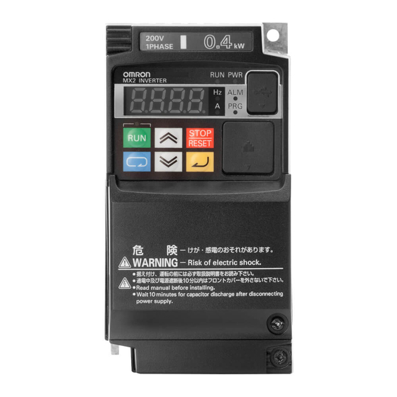
Page 54: Name Of Parts Of The Digital Operator
Digital Operator (factory default), it can be disabled by a Setting (b087).) If the Inverter is already tripped, the trip will be reset (return from the tripping). SYSDRIVE MX2 Series USER'S MANUAL (3G3MX2-A@@@@) - Page 55 Use this connector (RS-422) to connect the optional Remote Operator. Once the Remote Operator is connected, the keys on the main unit become disabled. In this case, use b150 to set the item to be displayed. SYSDRIVE MX2 Series USER'S MANUAL (3G3MX2-A@@@@)
-
Page 56: Monitor Mode
For details, refer to the next page. Function group "P" pk0k0k1 * Return to the function group "d" after the function group "U." uk0k0k1 Function group "U" dk0k0k1 Function group "d" Return to d001 SYSDRIVE MX2 Series USER'S MANUAL (3G3MX2-A@@@@) - Page 57 Output Frequency Monitor (d001) again. However, the selected mode continues to cycle among the function groups while the Mode Key is held, according to the designed operation of the key. (Example: A001→F001→b001→C001→...Elapse of 3 seconds, followed by display of "50.00") SYSDRIVE MX2 Series USER'S MANUAL (3G3MX2-A@@@@)
- Page 58 Note 2: Pressing the Increment and Decrement keys together in the individual input mode restores the normal input mode. Note 3: While the displayed data is blinking, the change has not yet reflected even when the function group is "F." SYSDRIVE MX2 Series USER'S MANUAL (3G3MX2-A@@@@)
- Page 59 Although operations can be performed by connecting the conventional Digital Operator model (3G3AX-OP01) to the 3G3MX2, the operations associated with the Mode key and Enter key vary from that of the conventional key operation system. To switch to the parameter display to data display, use the Enter key instead of the Mode key.
-
Page 60: Operation Method
5k0.0k0 The RUN key is enabled and the RUN command enabled LED indicator is lit when A002 is set to 02. Operation Refer to "Test Run" on page 3-10. SYSDRIVE MX2 Series USER'S MANUAL (3G3MX2-A@@@@) - Page 61 *2 This wiring diagram shows an example of using the built-in power supply of the Inverter. If an external power supply is used, refer to "Connection to Programmable Controller (PLC)" on page 2-22. Operation Refer to "Test Run" on page 3-10. SYSDRIVE MX2 Series USER'S MANUAL (3G3MX2-A@@@@)
-
Page 62: Test Run
*2 This wiring diagram shows an example of using the built-in power supply of the Inverter. If an external power supply is used, refer to "Connection to Programmable Controller (PLC)" on page 2-22. Operation Refer to "Test Run" on page 3-10. SYSDRIVE MX2 Series USER'S MANUAL (3G3MX2-A@@@@) -
Page 63: Test Run
T/L3(N)* W/T3 Motor Inverter * Connect to terminals L1 and N on a single-phase, 200-V Inverter (3G3MX2-AB@@@). Procedure for Test Run Command/Reference Input From the Digital Operator 1. Check if the wires are connected correctly. 2. Turn on the power of the Inverter. - Page 64 If an overcurrent or overvoltage tripping occurs during trial operation, try to increase the acceleration/deceleration time. Confirm by Output Current Monitor (d002) and DC Voltage Monitor (d102) to confirm that the current/voltage values are sufficiently away from the tripping values. 3-11 SYSDRIVE MX2 Series USER'S MANUAL (3G3MX2-A@@@@)
-
Page 65: Tripping
"Error Code List" in page 7-2. Reset * Perform a reset after identifying and removing the cause of the error and checking the various signals such as RUN Command. RS terminal input ON → OFF 3-12 SYSDRIVE MX2 Series USER'S MANUAL (3G3MX2-A@@@@) - Page 66 3-4 Tripping Alarm occurred RUN command FW, RV Free run Motor rotation speed RS (reset) input AL (alarm) output (alarm signal) 3-13 SYSDRIVE MX2 Series USER'S MANUAL (3G3MX2-A@@@@)
-
Page 67: Chapter4 Parameter List
Parameter List Describes the parameters used by this Unit. Monitor Mode ................ 4-1 Function Mode ..............4-4 SYSDRIVE MX2 Series USER'S MANUAL (3G3MX2-A@@@@) -
Page 68: Monitor Mode
− d009 Reference Monitor Torque Bias −200. to +200. − − − d010 Monitor Output Torque d012 −200. to +200. − − − Monitor Output Voltage − − − d013 0.0 to 600.0 Monitor SYSDRIVE MX2 Series USER'S MANUAL (3G3MX2-A@@@@) - Page 69 →Current (A) d083 Fault Monitor 3 − − − − 5-11 →Voltage between PNs (V) d084 Fault Monitor 4 →RUN time (h) →Power ON time (h) d085 Fault Monitor 5 d086 Fault Monitor 6 SYSDRIVE MX2 Series USER'S MANUAL (3G3MX2-A@@@@)
- Page 70 0.0 to 999.9 − − − d102 5-12 Monitor 1000. Regenerative − − − d103 Braking Load 0.0 to 100.0 5-12 Rate Monitor Electronic d104 Thermal Load 0.0 to 100.0 − − − 5-12 Rate Monitor SYSDRIVE MX2 Series USER'S MANUAL (3G3MX2-A@@@@)
-
Page 71: Function Mode
100.0 to 999.9 Time Setting 1 (30.00) 1000. to 3600. 0.01 to 99.99 Deceleration 10.00 F203 100.0 to 999.9 Time Setting 2 (30.00) 1000. to 3600. RUN Direction 00: Forward − F004 5-23 Selection 01: Reverse SYSDRIVE MX2 Series USER'S MANUAL (3G3MX2-A@@@@) - Page 72 − A016 31. (with 500 ms filter ±0.1 Hz 5-38 (FV, FI hysteresis) Sampling) A017 (Reserved) Do not change. − − − − *1. Enabled when the Digital Operator with Volume 3G3AX-OP01 is connected. SYSDRIVE MX2 Series USER'S MANUAL (3G3MX2-A@@@@)
- Page 73 A028 Speed 0.00 Reference 8 Multi-step A029 Speed 0.00 Reference 9 Multi-step A030 Speed 0.00 Reference 10 Multi-step A031 Speed 0.00 Reference11 Multi-step A032 Speed 0.00 Reference 12 Multi-step A033 Speed 0.00 Reference 13 SYSDRIVE MX2 Series USER'S MANUAL (3G3MX2-A@@@@)
- Page 74 Frequency 2 00: Constant torque characteristics (VC) 01: Reduced torque Control Method characteristics (VP 1.7th 5-46 A044 − power <VC, if low speed>) 5-144 02: Free V/f setting 03: Sensorless vector control (heavy load only) SYSDRIVE MX2 Series USER'S MANUAL (3G3MX2-A@@@@)
- Page 75 0. to 255. 100. Compensation Gain 2 5-49 Automatic Torque Boost − A047 Slip 0. to 255. 100. Compensation Gain 1 Automatic Torque Boost A247 Slip 0. to 255. 100. − Compensation Gain 2 SYSDRIVE MX2 Series USER'S MANUAL (3G3MX2-A@@@@)
- Page 76 0. to 100./70. (heavy load/light A057 Injection load) Braking Power Startup Internal A058 DC Injection 0.0 to 60.0 Braking Time 5-135 DC Injection 2.0 to 15.0/10.0 A059 Braking Carrier (heavy load/light load or high 5.0/2.0 Frequency frequency ) SYSDRIVE MX2 Series USER'S MANUAL (3G3MX2-A@@@@)
- Page 77 100.0 to 400.0 (1000.) Jump A068 Frequency 0.00 to 10.00 (100.0) 0.50 Width 3 Acceleration 0.00 to 99.99 A069 0.00 Stop Frequency 100.0 to 400.0 (1000.) 5-62 Acceleration A070 0.0 to 60.0 Stop Time 4-10 SYSDRIVE MX2 Series USER'S MANUAL (3G3MX2-A@@@@)
- Page 78 Selection 1 5-26 400V class: 380/400/415/440/ 5-148 Motor Incoming 200/ 460/480 A282 Voltage Selection 2 AVR Filter Time A083 0.000 to 10.00 0.300 Parameter 5-27 A084 Deceleration 50. to 200. 100. Voltage Gain 4-11 SYSDRIVE MX2 Series USER'S MANUAL (3G3MX2-A@@@@)
- Page 79 Monitor or data range Set data changed Unit Page setting during during RUN RUN Mode 00: Normal operation A085 − Selection 01: Energy-saving operation 5-79 Energy-saving Response/ − A086 0.0 to 100.0 50.0 Accuracy Adjustment 4-12 SYSDRIVE MX2 Series USER'S MANUAL (3G3MX2-A@@@@)
- Page 80 0.00 Frequency 1 2-step A296 Deceleration 0.00 Frequency 2 Acceleration A097 Pattern Selection 00: Linear 01: S shape − 02: U shape 5-68 03: Reverse-U shape 04: EL-S shape Deceleration A098 Pattern Selection 4-13 SYSDRIVE MX2 Series USER'S MANUAL (3G3MX2-A@@@@)
- Page 81 03: FI (current) input − 5-70 04: Modbus communication Operation (Modbus-RTU) A142 Frequency 05: Optional board Selection 2 07: Pulse train frequency *1. Enabled when the Digital Operator with Volume 3G3AX-OP01 is connected. 4-14 SYSDRIVE MX2 Series USER'S MANUAL (3G3MX2-A@@@@)
- Page 82 100.0 to 400.0 (1000.) A163 VR Start Ratio 0. to VR End Ratio 5-40 A164 VR End Ratio VR Start Ratio to 100 100. 00: Use Start Frequency VR Start A165 [A161] Selection 01: 0 Hz 4-15 SYSDRIVE MX2 Series USER'S MANUAL (3G3MX2-A@@@@)
- Page 83 Retry Selection 03: Trip after frequency matching deceleration stop 5-96 04: Frequency pull-in restart Allowable Momentary b002 Power 0.3 to 25.0 Interruption Time 5-96 Restart b003 0.3 to 100.0 5-100 Standby Time 5-103 4-16 SYSDRIVE MX2 Series USER'S MANUAL (3G3MX2-A@@@@)
- Page 84 Inverter Electronic b212 rated Thermal Level 2 current Electronic 5-110 Thermal b013 00: Reduced torque Characteristics characteristics Selection 1 01: Constant torque − Electronic characteristics Thermal 02: Free setting b213 Characteristics Selection 2 4-17 SYSDRIVE MX2 Series USER'S MANUAL (3G3MX2-A@@@@)
- Page 85 0.20 × Rated current to 2.00 × Rated current × rated current (heavy load Overload Limit 1 setting) 1.50 b025 0.20 × Rated current to 1.50 × Level 2 (heavy) rated current (light load or 1.20 setting) (light) 4-18 SYSDRIVE MX2 Series USER'S MANUAL (3G3MX2-A@@@@)
- Page 86 1000 to 6553 (100000 to 5-124 ON Time Level 655350) 00: No direction limit Rotation 01: Only Forward is enabled b035 Direction Limit (Reverse is limited) − 5-23 Selection 02: Only Reverse is enabled (Forward is limited) 4-19 SYSDRIVE MX2 Series USER'S MANUAL (3G3MX2-A@@@@)
- Page 87 LADSTOP 5-155 01: Enabled Selection Reverse Rotation 00: Disabled b046 − 5-157 Prevention 01: Enabled Selection Heavy Load/ 00: Heavy load mode b049 Light Load − 5-13 01: Light load mode Selection 4-20 SYSDRIVE MX2 Series USER'S MANUAL (3G3MX2-A@@@@)
- Page 88 Upper limit: (Upper limit level − Hysteresis Width Lower limit level)/2 Analog Operation Level 0. to 100. − b070 at FV no (ignore) Disconnection 5-132 Analog Operation Level 0. to 100. − b071 at FI no (ignore) Disconnection 4-21 SYSDRIVE MX2 Series USER'S MANUAL (3G3MX2-A@@@@)
- Page 89 (including 5 minutes after b092 − Operation power on/stop) 02: Depends on the fin 5-127 temperature Cooling Fan 00: Total operation time count − b093 Total Operation 01: Clear total operation time Time Clear 4-22 SYSDRIVE MX2 Series USER'S MANUAL (3G3MX2-A@@@@)
- Page 90 Frequency 6 V/f Frequency 7 5-47 Free V/f b111 0.0 to 800.0 Voltage 6 Free V/f Free V/f Frequency 6 to 400. b112 Frequency 7 (1000.) Free V/f b113 0.0 to 800.0 Voltage 7 4-23 SYSDRIVE MX2 Series USER'S MANUAL (3G3MX2-A@@@@)
- Page 91 − Target 1 d001 to d030) 5-10 d050 Monitor 001 to 030 (corresponding to − b161 Target 2 d001 to d030) d001/d007 Frequency 00: Disabled − b163 Setting Mode 01: Enabled Selection 4-24 SYSDRIVE MX2 Series USER'S MANUAL (3G3MX2-A@@@@)
- Page 92 Password A − b191 0000 to FFFF 0000 Authentication 5-91 0000: Password function Password B − b192 disabled 0000 Setting 0001 to FFFF: Password Password B b193 0000 to FFFF 0000 − Authentication 4-25 SYSDRIVE MX2 Series USER'S MANUAL (3G3MX2-A@@@@)
- Page 93 83: HLD (Retain output frequency) Multi-function 84: ROK (Permission of RUN command) 85: EB (Rotation direction detection (C007 only)) C007 Input 7 06 (JG) 86: DISP (Display fixed) Selection no: NO (Not assigned) 4-26 SYSDRIVE MX2 Series USER'S MANUAL (3G3MX2-A@@@@)
- Page 94 00: NO (NO contact) C014 − 5-31 Operation 01: NC (NC contact) Selection Multi-function Input Terminal 5 C015 Operation Selection Multi-function Input Terminal 6 C016 Operation Selection Multi-function Input Terminal 7 C017 Operation Selection 4-27 SYSDRIVE MX2 Series USER'S MANUAL (3G3MX2-A@@@@)
- Page 95 55: WCFI (Window comparator FI) Selection 58: FREF (Frequency command source) 59: REF (RUN command source) 60: SETM (Motor 2 selection) 62: EDM (Safety device monitor) 63: OPO (Optional board) no: NO (Not assigned) 4-28 SYSDRIVE MX2 Series USER'S MANUAL (3G3MX2-A@@@@)
- Page 96 00: NO contact at P1, P2, Output Terminal C032 MA, NC contact at MB − P2 Contact 5-34 01: NC contact at P1, P2, Selection MA, NO contact at MB Multi-function Relay Output C036 (MA, MB) Contact Selection 4-29 SYSDRIVE MX2 Series USER'S MANUAL (3G3MX2-A@@@@)
- Page 97 Deceleration 2 Pulse Train − C047 Output 0.01 to 99.99 1.00 5-43 Coefficient Feedback C052 Comparison 0.0 to 100.0 100.0 Signal Off Level 5-73 Feedback C053 Comparison 0.0 to 100.0 Signal On Level 4-30 SYSDRIVE MX2 Series USER'S MANUAL (3G3MX2-A@@@@)
- Page 98 Communication − C072 Station No. 1. to 247. Selection 00: No parity Communication − C074 01: Even Parity Selection 02: Odd Communication 1: 1 bit − C075 Stop Bit 2: 2 bits Selection 4-31 SYSDRIVE MX2 Series USER'S MANUAL (3G3MX2-A@@@@)
- Page 99 Co-inverter Communication − C098 1. to 8. 6-22 Starting Station Number Co-inverter Communication C099 1. to 8. − Ending Station Number Co-inverter 00: 485 terminal C100 Communication − 01: Always started Start Selection 4-32 SYSDRIVE MX2 Series USER'S MANUAL (3G3MX2-A@@@@)
- Page 100 AM Gain C106 50. to 200. 100. 5-45 Adjustment C109 AM Bias Setting 0. to 100. 5-45 Rated Overload 1 C111 0.00 to 2.00 × Rated current current 5-115 Warning Level 2 × 1.15 4-33 SYSDRIVE MX2 Series USER'S MANUAL (3G3MX2-A@@@@)
- Page 101 (33 (LOG1), 34 (LOG2), 35 C149 Signal 3 (LOG3), 62 (EDM), 63 − Selection 2 (OPO), and "no" cannot be selected.) Logic Output 00: AND Signal 3 − C150 01: OR Operator 02: XOR Selection 4-34 SYSDRIVE MX2 Series USER'S MANUAL (3G3MX2-A@@@@)
- Page 102 15.0/18.5 H203 Motor Capacity 2 setting 5-145 Motor Pole H004 Number 1 2/4/6/8/10 pole Motor Pole H204 Number 2 Speed H005 100. Response 1 1. to 1000. − Speed H205 100. Response 2 4-35 SYSDRIVE MX2 Series USER'S MANUAL (3G3MX2-A@@@@)
- Page 103 Parameter Io capacity Depends Motor 1 H024 on the 0.001 to 9.999 Parameter J capacity 10.00 to 99.99 100.0 to 999.9 Depends Motor 2 1000. to 9999. H224 on the Parameter J capacity 4-36 SYSDRIVE MX2 Series USER'S MANUAL (3G3MX2-A@@@@)
- Page 104 (Auto-tuning capacity Data) V/f Control with Speed Feedback Slip H050 0.00 to 10.0 0.20 Time Compensation Proportional 5-83 Gain 5-160 V/f Control with Speed H051 Feedback Slip 0.0. to 100.0 Compensation Integral Gain 4-37 SYSDRIVE MX2 Series USER'S MANUAL (3G3MX2-A@@@@)
- Page 105 P036 Torque Bias Mode − Operator 05: Optional board 5-156 P037 Torque Bias Value −200. to +200. 00: As per sign Torque Bias − P038 01: Depends on the RUN Polarity Selection direction 4-38 SYSDRIVE MX2 Series USER'S MANUAL (3G3MX2-A@@@@)
- Page 106 1.0 to 32.0 25.0 Frequency Scale Pulse Train P056 Frequency Filter 0.01 to 2.00 0.10 5-82 Time Parameter Pulse Train Bias −100. to +100. P057 Amount P058 Pulse Train Limit 0. to 100. 100. 4-39 SYSDRIVE MX2 Series USER'S MANUAL (3G3MX2-A@@@@)
- Page 107 Position Range −268435455 − P073 Setting (Reverse (Displays MSB 4 digits Side) including "−") 5-160 Positioning 00: Limit − P075 Mode Selection 01: Not limited Encoder P077 Disconnection 0.0 to 10.0 Detection Time 4-40 SYSDRIVE MX2 Series USER'S MANUAL (3G3MX2-A@@@@)
- Page 108 P106 P107 P108 P109 P110 P111 P112 P113 P114 P115 − − − − − − (Reserved) P116 P117 P118 P119 P120 P121 P122 P123 P124 P125 P126 P127 P128 P129 P130 P131 4-41 SYSDRIVE MX2 Series USER'S MANUAL (3G3MX2-A@@@@)
- Page 109 0000 6-22 inverter Communication Sender Register of All Stations in − P143 Co-inverter 0000 to FFFF Hex 0000 Communication Recipient Station Number of All Stations in − P144 1. to 247. Co-inverter Communication 4-42 SYSDRIVE MX2 Series USER'S MANUAL (3G3MX2-A@@@@)
- Page 110 Co-inverter Communication Recipient Register of All Stations in Co- P151 0000 to FFFF Hex 0000 − inverter Communication Sender Register of All Stations in P152 Co-inverter 0000 to FFFF Hex 0000 − Communication 4-43 SYSDRIVE MX2 Series USER'S MANUAL (3G3MX2-A@@@@)
- Page 111 Communication P160 P161 P162 P163 P164 P165 P166 P167 P168 P169 P170 P171 − − − − − − P172 (Reserved) P173 P174 P175 P176 P177 P178 P179 P180 P181 P182 P185 P186 4-44 SYSDRIVE MX2 Series USER'S MANUAL (3G3MX2-A@@@@)
- Page 112 Selection User 17 U017 Selection User 18 U018 Selection User 19 U019 Selection User 20 U020 Selection User 21 U021 Selection User 22 U022 Selection User 23 U023 Selection User 24 U024 Selection 4-45 SYSDRIVE MX2 Series USER'S MANUAL (3G3MX2-A@@@@)
- Page 113 User 26 U026 Selection User 27 U027 Selection User 28 U028 Selection − 5-177 d001 to P186 User 29 U029 Selection User 30 U030 Selection User 31 U031 Selection User 32 U032 Selection 4-46 SYSDRIVE MX2 Series USER'S MANUAL (3G3MX2-A@@@@)
- Page 115 Rotation Direction Limit Selection ..........5-23 Stop Selection................5-24 Acceleration/Deceleration Time ............ 5-24 Base Frequency................5-26 AVR Function................5-27 Maximum Frequency ..............5-28 Input/Output Terminals ............5-29 Multi-function Input Selection............5-29 Multi-function Input Operation Selection ........5-31 SYSDRIVE MX2 Series USER'S MANUAL (3G3MX2-A@@@@)
- Page 116 Power Recovery Restart Prevention Function (USP) ....5-105 Deceleration Stop at Power-off (Controlled Deceleration on Power Loss Function) ...5-106 Functions Relating to Protections, Warnings and Various Output Signals ..5-110 Electronic Thermal Function ............5-110 Overload Limit/Overload Warning ..........5-114 SYSDRIVE MX2 Series USER'S MANUAL (3G3MX2-A@@@@)
- Page 117 How to Wire for/Use Safety Function.......... 5-171 Wiring Example................5-172 5-14 Other Functions ..............5-174 Initialization Setting ..............5-174 User Parameter Manual Setting Function........5-177 User Parameter Automatic Setting Function....... 5-177 Inverter Mode Selection .............. 5-178 SYSDRIVE MX2 Series USER'S MANUAL (3G3MX2-A@@@@)
-
Page 118: Monitor Mode
The monitor LED indicator "A" is lit while the d002 setting is displayed. Parameter Default Function name Data Unit setting 0.0 to 655.3 Output Current d002 The minimum unit varies depending on − Monitor the capacity. SYSDRIVE MX2 Series USER'S MANUAL (3G3MX2-A@@@@) -
Page 119: Rotation Direction Monitor [D003]
1.) 1,000 to 9,999 (Displayed in increments of 10.) 100 to 999 (Displayed in increments of 1,000.) 0.01 to 99.99 (Displayed in increments of A075 PID Scale 1.00 Time 0.01.) Related functions A071, A075 SYSDRIVE MX2 Series USER'S MANUAL (3G3MX2-A@@@@) -
Page 120: Multi-Function Input Monitor [D005]
This does not depend on the NO/NC contact setting. Example) Multi-function output terminals P2, P1/EDM : ON Relay output terminal MA : OFF Display : Lit : Turned OFF MA P2 P1 (OFF)(ON) (ON) SYSDRIVE MX2 Series USER'S MANUAL (3G3MX2-A@@@@) -
Page 121: Output Frequency Monitor (After Conversion) [D007]
While the PID function is activated or being stopped, the output frequency cannot be changed. The frequency cannot be changed in the individual input mode by pressing the Increment/ Decrement keys simultaneously. SYSDRIVE MX2 Series USER'S MANUAL (3G3MX2-A@@@@) -
Page 122: Real Frequency Monitor [D008]
ATR terminal is turned ON. For details, refer to "Torque Control" on page 5-156. Parameter Default Function name Data Unit setting Torque Reference −200. to 200. d009 − Monitor Related functions A044, C001 to C007, P033, P034 SYSDRIVE MX2 Series USER'S MANUAL (3G3MX2-A@@@@) -
Page 123: Torque Bias Monitor [D010]
Displays the output voltage of the Inverter. Parameter Default Function name Data Unit setting Output Voltage 0.0 to 600.0 d013 − Monitor Set Motor Incoming Voltage Selection (A082/A282) correctly. The correct value may not be displayed. SYSDRIVE MX2 Series USER'S MANUAL (3G3MX2-A@@@@) -
Page 124: Input Power Monitor [D014]
01: Perform integrated power clear (01 Clear is reset to 00 after the clear.) Integrated Power 1. to 1000. − b079 Display Scale Multi-function Input 53: KHC (Integrated power clear) C001 to C007 − − Selection SYSDRIVE MX2 Series USER'S MANUAL (3G3MX2-A@@@@) -
Page 125: Total Run Time [D016]
Note: Initialization will not clear the setting. Fin Temperature Monitor [d018] Displays the temperature of the cooling fin inside the Inverter. Parameter Default Function name Data Unit setting −20.0 to 150.0 − °C d018 Fin Temperature Monitor SYSDRIVE MX2 Series USER'S MANUAL (3G3MX2-A@@@@) -
Page 126: Life Assessment Monitor [D022]
Displays MSB 4 digits for forward position. Displays (−) and MSB 3 digits Current Position for reverse position. d030 − − (Example) Current position 1560000 → Monitor Displays as 1560 Current position −1560000 → Displays as −156 SYSDRIVE MX2 Series USER'S MANUAL (3G3MX2-A@@@@) -
Page 127: User Selection Monitor (2 Types) [D050]
The Inverter mode is changed using b171. For details, refer to "Inverter Mode Selection" on page 5-178. Parameter Default Function name Data Unit setting IM (induction motor) heavy load mode Inverter Mode − − d060 IM (induction motor) light load mode Monitor IM (induction motor) high-frequency mode 5-10 SYSDRIVE MX2 Series USER'S MANUAL (3G3MX2-A@@@@) -
Page 128: Fault Counter [D080]
If the set data is inconsistent with other data, a warning is displayed. While a warning is present, the Program LED (PRG) indicator remains lit until the data is corrected. For details on the Warning display, refer to "Warning Display" on page 7-7. 5-11 SYSDRIVE MX2 Series USER'S MANUAL (3G3MX2-A@@@@) -
Page 129: Dc Voltage Monitor [D102]
When the power is shut off, the displayed value changes to 0. Also when totaling does not occur for 10 minutes, the displayed value changes to 0. Parameter Default Function name Data Unit setting Electronic Thermal Load 0.0 to 100.0 − d104 Rate Monitor 5-12 SYSDRIVE MX2 Series USER'S MANUAL (3G3MX2-A@@@@) -
Page 130: Basic Functions
00: Constant 00: Constant 00: Constant 00: Constant torque torque torque torque 01: Reduced 01: Reduced Control Method torque torque A044/A244 02: Free V/f 02: Free V/f setting setting 03: Sensorless vector control 5-13 SYSDRIVE MX2 Series USER'S MANUAL (3G3MX2-A@@@@) - Page 131 Reverse Rotation Prevention Motor 1/2 Parameter Io b046 H033/H233 Selection (Auto-tuning Data) Motor 1/2 Parameter J C054 Overtorque/Undertorque Selection H034/H234 (Auto-tuning Data) Overtorque Level C055 P033 Torque Reference Input Selection (Forward Power Running) 5-14 SYSDRIVE MX2 Series USER'S MANUAL (3G3MX2-A@@@@)
-
Page 132: Frequency Reference Selection And Output Frequency Setting
Frequency Reference Selection (A001), A001 need not be set. Only when all multi-step speed inputs are OFF and therefore 0th is specified, the frequency conforms to the setting of A001. 5-15 SYSDRIVE MX2 Series USER'S MANUAL (3G3MX2-A@@@@) - Page 133 (A001/A201 = 01), and the Digital Operator with volume 3G3AX-OP01, allocate the FV/FI terminal (16: FV/FI) to a multi-function input. The detailed setting method is explained below. (A005: FV/FI Selection) 5-16 SYSDRIVE MX2 Series USER'S MANUAL (3G3MX2-A@@@@)
- Page 134 02: Switch between FV (voltage)/ − A005 FV/FI Selection Volume 16: FV/FI (Analog input switch) Multi-function C001 to C007 ON: Volume − − Input Selection OFF: Voltage *1.Volume: Volume on the external Digital Operator 3G3AX-OP01. 5-17 SYSDRIVE MX2 Series USER'S MANUAL (3G3MX2-A@@@@)
- Page 135 Specified by a Sum of Analog Voltage and Analog Current Parameter Default Function name Data Unit setting Frequency Reference − A001 01: Control circuit terminal block Selection 1 − Multi-function − − C001 to C007 Input Selection (Need not be allocated) 5-18 SYSDRIVE MX2 Series USER'S MANUAL (3G3MX2-A@@@@)
- Page 136 Random A020 to A220 6.00 Reference 0 Multi-step Speed Random A021 to A035 0.00 Reference 1 to 15 *1.Only when the speed is 0th the frequency reference conforms to the setting of A001. 5-19 SYSDRIVE MX2 Series USER'S MANUAL (3G3MX2-A@@@@)
- Page 137 ON: Control circuit terminal block − − Input Selection OFF: According to A001 Reference If the forced operator terminal and forced terminal block terminal are both turned ON, the forced operator function is given priority. 5-20 SYSDRIVE MX2 Series USER'S MANUAL (3G3MX2-A@@@@)
- Page 138 Digital Operator, F001 shows a monitored value of the specified frequency. If Frequency Change is enabled (b163 = 01) during monitoring, the frequency can be changed by pressing the Up/Down keys on the d001 or d007 monitor display. 5-21 SYSDRIVE MX2 Series USER'S MANUAL (3G3MX2-A@@@@)
-
Page 139: Run Command Selection
REV RUN key STOP key Operator Modbus communications (A002 = 03) Forward command Reverse command Stop command Optional board (A002 = 04) Operation stops when the FW terminal and RV terminal are both turned ON. 5-22 SYSDRIVE MX2 Series USER'S MANUAL (3G3MX2-A@@@@) -
Page 140: Run Direction Selection
Operator displays OkOkOkO Parameter Default Function name Data Unit setting 00: No direction limit 01: Only Forward is enabled Rotation Direction − b035 (No Reverse) Limit Selection 02: Only Reverse is enabled (No Forward) 5-23 SYSDRIVE MX2 Series USER'S MANUAL (3G3MX2-A@@@@) -
Page 141: Stop Selection
0. 00: Digital Operator Acceleration/Deceleration − P031 Time Input Type 03: Do not set. Multi-function Input 46: LAC (LAD cancel) C001 to C007 − − Selection Related functions A004/A204, P031, C001 to C007 5-24 SYSDRIVE MX2 Series USER'S MANUAL (3G3MX2-A@@@@) - Page 142 : Motor rotation speed (r/min) : Maximum acceleration torque based on inverter drive (N • : Maximum deceleration torque based on inverter drive (N Deceleration time T • : Required running torque (N • × × 9.55 5-25 SYSDRIVE MX2 Series USER'S MANUAL (3G3MX2-A@@@@)
-
Page 143: Base Frequency
A003/A203 Base Frequency 1/2 (1000.0) 200V class: 200/215/220/230/240 Motor Incoming A082/A282 400V class: 380/400/415/440/460/ Voltage Selection 1/2 Related functions A081, A082 Output voltage Motor incoming A082/A282 voltage selection Output frequency (Hz) Base frequency 5-26 SYSDRIVE MX2 Series USER'S MANUAL (3G3MX2-A@@@@) -
Page 144: Avr Function
Motor incoming voltage selection voltage selection (A082/A282) Output voltage when the AVR selection is ON Start deceleration Time (s) Time (s) Example of setting the AVR Selection OFF during deceleration (A081 = 02) 5-27 SYSDRIVE MX2 Series USER'S MANUAL (3G3MX2-A@@@@) -
Page 145: Maximum Frequency
Switch between Motor 1 and Motor 2 using the input terminal allocated to 08 (SET). Example) A020: Frequency of Motor 1 at Multi-step Speed 1 Reference 0 A220: Frequency of Motor 2 at Multi-step Speed 2 Reference 0 5-28 SYSDRIVE MX2 Series USER'S MANUAL (3G3MX2-A@@@@) -
Page 146: Input/Output Terminals
Prevention Function CS: Commercial switch Commercial Switching 5-79 SFT: Soft lock Soft Lock 5-84 FV/FI: Analog input switch Analog Input 5-37 RS: Reset Reset 5-100 TH: PTC thermistor thermal Thermistor Trip Function 5-120 protection 5-29 SYSDRIVE MX2 Series USER'S MANUAL (3G3MX2-A@@@@) - Page 147 F-TM: Forced terminal block Forced Terminal Block Function 5-85 ATR: Torque reference input Torque Control 5-156 permission KHC: Integrated power clear Integrated Power Monitor − − Reserved. AHD: Analog command held Analog Command Hold Function 5-39 5-30 SYSDRIVE MX2 Series USER'S MANUAL (3G3MX2-A@@@@)
-
Page 148: Multi-Function Input Operation Selection
Actual input signal status recognized by the values Inverter OFF (Open = No conduction) Normal (NO contact) ON (Closed = Conduction) Operating Normal ON (Closed = Conduction) (NC contact) Operating OFF (Open = No conduction) 5-31 SYSDRIVE MX2 Series USER'S MANUAL (3G3MX2-A@@@@) -
Page 149: Input Terminal Response Time
THM: Thermal warning Electronic Thermal Function 5-113 BRK: Brake release Brake Control Function 5-142 BER: Brake error ZS: 0Hz 0-Hz Signal (ZS) 5-125 DSE: Excessive speed deviation Simple Position Control Mode 5-160 POK: Position ready 5-32 SYSDRIVE MX2 Series USER'S MANUAL (3G3MX2-A@@@@) - Page 150 REF: RUN command source RUN Command Status Signal 5-133 SETM: Motor 2 selection Motor 2 Control Selected Signal 5-134 EDM: Safety device monitor Safety Function 5-170 OPO: Optional board − − − − no: Not assigned 5-33 SYSDRIVE MX2 Series USER'S MANUAL (3G3MX2-A@@@@)
-
Page 151: Multi-Function Output Terminal Contact Selection
Below are the specifications of multi-function output terminals P1/EDM and P2. Inverter interior Electrical characteristics Between each terminal and PC Voltage drop 4 V max. at power-on Max. allowable voltage: 27 VDC Allowable max. current: 50 mA 5-34 SYSDRIVE MX2 Series USER'S MANUAL (3G3MX2-A@@@@) - Page 152 5 VDC, 100 mA Max. contact 250 VAC, 1 A 250 VAC, 0.2 A capacity 30 VDC, 1 A 30 VDC, 0.2 A MB-MC Min. contact 100 VAC, 10 mA capacity 5 VDC, 100 mA 5-35 SYSDRIVE MX2 Series USER'S MANUAL (3G3MX2-A@@@@)
-
Page 153: Output Signal Delay/Hold Function
C130/C132 0.0 to 100.0 Delay Time Output P1/EDM OFF C131/C133 0.0 to 100.0 Delay Time Output RY ON Delay C140 0.0 to 100.0 Time Output RY OFF Delay C141 0.0 to 100.0 Time 5-36 SYSDRIVE MX2 Series USER'S MANUAL (3G3MX2-A@@@@) -
Page 154: Analog Signal
*3.Even when the specified analog input is overlapping with the target value or feedback value, the setting of A079 is applied as is. *4.Only the analog voltage 10 V = 200% of the torque limit value. The FV/FI terminal is not allocated. 5-37 SYSDRIVE MX2 Series USER'S MANUAL (3G3MX2-A@@@@) -
Page 155: Analog Input Filter (Fv, Fi Sampling)
Default Function name Data Unit setting 1. to 30.: Set value × 2 ms filter Analog Input Filter − A016 31.: Fixed to 500 ms filter (FV, FI Sampling) With ±0.1 Hz hysteresis 5-38 SYSDRIVE MX2 Series USER'S MANUAL (3G3MX2-A@@@@) -
Page 156: Analog Command Held Function (Ahd)
To switch the control function, turn OFF the AHD terminal once, and keep the analog signal on hold again. If this function is frequently used, the internal EEROM element service life may be shortened. 5-39 SYSDRIVE MX2 Series USER'S MANUAL (3G3MX2-A@@@@) -
Page 157: Analog Input Adjustment
Note 1: To input current between 4 and 20 mA, set A103 to 20%. (Default value: 20% = 20 mA × 20% = 4 mA) Note 2: To input voltage between 0 and 5 V, set A014 to 50%. 5-40 SYSDRIVE MX2 Series USER'S MANUAL (3G3MX2-A@@@@) - Page 158 0 % or greater The output frequencies of A013/A103/A163 A011/A101/A161 are 0 Hz. A013/ A014/ 100 % Analog input A103/ A104/ (FV/FI) A163 A164 (0 V) (10 V) (0 mA) (20 mA) (VR minimum) (VR maximum) 5-41 SYSDRIVE MX2 Series USER'S MANUAL (3G3MX2-A@@@@)
-
Page 159: Mp Terminal (Pulse/Pwm Output)
*2.This setting is effective only when the control method is Sensorless Vector Control (A044/A244 = 03). *3.If Frequency Conversion Coefficient (b086) is set, a gain-converted value is output for the digital output frequency. Refer to "Output Frequency Monitor [d001]" on page 5-1. 5-42 SYSDRIVE MX2 Series USER'S MANUAL (3G3MX2-A@@@@) - Page 160 Output pulse frequency = Input pulse 1.00 Coefficient frequency × (C047) Example 1) PWM output Example 2) Pulse output Cycle T: Constant (6.4 ms) Cycle T: Variable Duty t/T : Variable Duty t/T : Fixed to 5-43 SYSDRIVE MX2 Series USER'S MANUAL (3G3MX2-A@@@@)
-
Page 161: Am Terminal (Analog Output)
Note: If "00: Output frequency" is monitored during deceleration due to overload limit, the displayed value may seem unstable in the low-speed range. In this case, changing the selection to "07: LAD frequency" stabilizes the displayed value. 5-44 SYSDRIVE MX2 Series USER'S MANUAL (3G3MX2-A@@@@) - Page 162 Set an offset for the AM monitor. Note: When a reset signal is input, the offset becomes 0% once. Example) AM provides 4 to 20 mA output, the offset value is 20% (= 4 / 20). (Default value) 5-45 SYSDRIVE MX2 Series USER'S MANUAL (3G3MX2-A@@@@)
-
Page 163: Settings Relating To Control Method
While the output voltage is proportional from 0 Hz to base frequency, the output voltage is constant from base to maximum frequency regardless of the frequency. Output voltage (100 %) Output frequency (Hz) Base frequency Maximum frequency 5-46 SYSDRIVE MX2 Series USER'S MANUAL (3G3MX2-A@@@@) -
Page 164: Free V/F Setting
Free V/f Frequency 3 (f3) free V/f frequency 4 Free V/f frequency 1 to b102 Free V/f Frequency 2 (f2) free V/f frequency 3 b100 Free V/f Frequency 1 (f1) 0. to Free V/f frequency 2 5-47 SYSDRIVE MX2 Series USER'S MANUAL (3G3MX2-A@@@@) - Page 165 An improper setting causes overcurrent during acceleration or deceleration, or vibration of the motor and/or machine. Output voltage (V) Selection of voltage or motor voltage that can be output Output frequency (Hz) (Example) Output voltage (%) V2,V3 Output frequency (Hz) 5-48 SYSDRIVE MX2 Series USER'S MANUAL (3G3MX2-A@@@@)
-
Page 166: Torque Boost
100%. Switch between Controls 1/2 using the SET terminal which is a multi-function input terminal to which "08: SET" is allocated. Output voltage (%) A042/A242 Output frequency A043/A243 Base frequency (100 %) 5-49 SYSDRIVE MX2 Series USER'S MANUAL (3G3MX2-A@@@@) -
Page 167: Automatic Torque Boost
(1) Gradually reduce the Automatic Torque Boost A046/A246 Voltage Compensation Gain. Overcurrent trip occurs when (2) Gradually reduce the Automatic Torque Boost Slip A047/A247 load is applied. Compensation Gain. (3) Gradually reduce the Manual Torque Boost Voltage A042/A242 Setting. 5-50 SYSDRIVE MX2 Series USER'S MANUAL (3G3MX2-A@@@@) -
Page 168: Carrier Frequency
Raising the carrier frequency reduces the DC braking force. For details, refer to "DC Injection Braking (DB)" on page 5-135. Carrier frequency and Extent of impact Carrier frequency High Motor noise Large Small Noise/leak current Small Large Torque Large Small Carrier frequency: Low Carrier frequency: High 5-51 SYSDRIVE MX2 Series USER'S MANUAL (3G3MX2-A@@@@) -
Page 169: Automatic Carrier Frequency Reduction Function
96% (91%) of the rated current When b089 set to 01 Carrier frequency 15.0 kHz 12.0 kHz 9.0 kHz 6.0 kHz 3.0 kHz Output current (%) 60 % 72 % 84 % 96 % 5-52 SYSDRIVE MX2 Series USER'S MANUAL (3G3MX2-A@@@@) - Page 170 The upper limit of Carrier Frequency (b083) variable with this function conforms to the set value of carrier frequency b083, and the lower limit is 3 kHz. If b083 is 3 kHz or below, this function is disabled regardless of the setting of b089. 5-53 SYSDRIVE MX2 Series USER'S MANUAL (3G3MX2-A@@@@)
-
Page 171: Motor 2 Control Function (Set)
Deceleration Time 2 A094 A294 2-step Acceleration/Deceleration Selection A095 A295 2-step Acceleration Frequency A096 A296 2-step Deceleration Frequency b012 b212 Electronic Thermal Level b013 b213 Electronic Thermal Characteristics Selection b021 b221 Overload Limit Selection 5-54 SYSDRIVE MX2 Series USER'S MANUAL (3G3MX2-A@@@@) - Page 172 The control functions 1/2 cannot be switched during operation. Switching is possible only while operation is stopped, which means that the functions will switch after the operation stops. Motor 1 SET terminal OFF: Control 1 (motor 1) OFF: Control 2 (motor 2) Motor 2 Inverter 5-55 SYSDRIVE MX2 Series USER'S MANUAL (3G3MX2-A@@@@)
-
Page 173: Operation Functions
Multi-function − − C001 to C007 21: STP (3-wire stop) Input Selection 22: F/R (3-wire forward/reverse) Related functions A002 STA input (start) STP input (stop) F/R input (forward/reverse switching) Forward Output frequency Reverse 5-56 SYSDRIVE MX2 Series USER'S MANUAL (3G3MX2-A@@@@) -
Page 174: Starting Frequency
Parameter Default Function name Data Unit setting Starting 0.10 to 9.99 (100.00) b082 0.50 Frequency RUN command (FW input) b082 Output frequency Output voltage 5-57 SYSDRIVE MX2 Series USER'S MANUAL (3G3MX2-A@@@@) -
Page 175: Reduced Voltage Startup Selection
RUN command (FW input) (FW input) Starting frequency Starting frequency b082 b082 Output Output frequency frequency Output Output voltage voltage Small Large b036 b036 = 00 Reduced voltage startup disabled Reduced voltage startup enabled 5-58 SYSDRIVE MX2 Series USER'S MANUAL (3G3MX2-A@@@@) -
Page 176: Jogging Operation (Jg)
(Even when the RUN command source is the Digital Operator, issue a RUN command after turning ON the JG terminal.) Also note that the frequency reference can be changed by F001 even during jogging operation. 5-59 SYSDRIVE MX2 Series USER'S MANUAL (3G3MX2-A@@@@) -
Page 177: Frequency Limit
Function name Data Unit setting Frequency Upper 0.00, frequency lower limit 1/2 to A061/A261 0.00 Limit 1/2 maximum frequency Frequency Lower 0.00, starting frequency to 1/2 frequency A062/A262 0.00 Limit 1/2 upper limit 5-60 SYSDRIVE MX2 Series USER'S MANUAL (3G3MX2-A@@@@) -
Page 178: Frequency Jump Function
Set one-half of the frequency width in 0.50 A068 1/2/3 which to execute a jump. *1.If 0 Hz is set, this function is disabled. Output frequency A068 A067 A068 A066 A065 A066 A064 A063 A064 Frequency reference 5-61 SYSDRIVE MX2 Series USER'S MANUAL (3G3MX2-A@@@@) -
Page 179: Acceleration/Deceleration Stop Function
− − C001 to C007 Selection (1) Automatic Stopping at a Desired Frequency/Stopping Time Output frequency A154 A155 A069 A070 Time (2) Stopping with a Multi-function Input Terminal Output frequency Time HLD input 5-62 SYSDRIVE MX2 Series USER'S MANUAL (3G3MX2-A@@@@) -
Page 180: Run Permission Signal
C001 to C007 − − Selection 32 to 38 Bit operation, 8 steps (SF1 to SF7) Multi-step Speed/ 0. to 200. (× 10 ms) C169 Position Wait time until determination of Determination Time terminal input 5-63 SYSDRIVE MX2 Series USER'S MANUAL (3G3MX2-A@@@@) -
Page 181: Binary Operation
7 Speed OFF OFF OFF reference 8 Speed OFF OFF reference 9 Speed reference 10 Speed reference 11 Speed OFF OFF reference 12 Speed reference 13 Speed reference 14 Speed reference 15 5-64 SYSDRIVE MX2 Series USER'S MANUAL (3G3MX2-A@@@@) -
Page 182: Bit Operation
When several terminals are simultaneously turned on, priority is given to the terminal with the smallest number. The × mark in the above table means that speed is selected regardless of ON/OFF status. 5-65 SYSDRIVE MX2 Series USER'S MANUAL (3G3MX2-A@@@@) -
Page 183: 2-Step Acceleration/Deceleration Function (2Ch)
Example 1) Switching via Input Terminal (A094/A294 = 00) FW input 2CH input Output frequency Acceleration Deceleration Deceleration Acceleration time 2 time 2 time 1 time 1 F002/ A092/ A093/ F003/ F202 A292 A293 F203 5-66 SYSDRIVE MX2 Series USER'S MANUAL (3G3MX2-A@@@@) - Page 184 Example 3) Forward/Reverse Switching (A094/A294 = 02) FW input RV input Deceleration Acceleration time 1 time 2 A092/ F003/ A292 F203 Output frequency Acceleration Deceleration time 1 time 2 F002/ A093/ F202 A293 5-67 SYSDRIVE MX2 Series USER'S MANUAL (3G3MX2-A@@@@)
-
Page 185: Acceleration/Deceleration Pattern
(for a winding stop as with the S shape, before reaching the set the elevating machine, etc.). but the intermediate output frequency value. machine or conveyor. section is linear. 5-68 SYSDRIVE MX2 Series USER'S MANUAL (3G3MX2-A@@@@) - Page 186 Output frequency ratio (%) EL-S Shape Deceleration EL-S Shape Curve Ratio 1 Acceleration (A152) Curve Ratio 2 (A151) EL-S Shape Deceleration Ratio 2 (A153) EL-S Shape Acceleration Time (s) Curve Ratio 1 (A150) 5-69 SYSDRIVE MX2 Series USER'S MANUAL (3G3MX2-A@@@@)
-
Page 187: Frequency Operation Function
Note 1: The remote operation function cannot be used when this function is enabled. Also, frequency cannot be changed through key operations of Output Frequency Monitor (d001), Output Frequency Monitor (After Conversion) (d007), or Output Frequency Setting (F001). Note 2: The same setting is available in A141/A142. 5-70 SYSDRIVE MX2 Series USER'S MANUAL (3G3MX2-A@@@@) -
Page 188: Frequency Addition Function
C001 to C007 − − Selection decelerated) 29: UDC (UP/DWN function data clear) *1.Do not turn ON/OFF the UP/DWN terminal after shutting off the power. Otherwise, the Inverter may not store data normally. 5-71 SYSDRIVE MX2 Series USER'S MANUAL (3G3MX2-A@@@@) -
Page 189: Output Voltage Gain
Set the rate of reduction of output Output Voltage A045/A245 voltage. 100. Gain 1/2 20. to 100. Related functions A082 A082(100 %) Motor incoming A282(100 %) voltage selection A082 × A045(%) A045/A245 A282 × A245(%) Base frequency Maximum frequency 5-72 SYSDRIVE MX2 Series USER'S MANUAL (3G3MX2-A@@@@) -
Page 190: Pid Function
0 to 10V − Selection 02: FI (current) 4 to 20 mA 0.0 to 400.0(1000.) PID Sleep Function A156 Operation stops once the PID output 0.00 Operation Level drops to below the operation level. 5-73 SYSDRIVE MX2 Series USER'S MANUAL (3G3MX2-A@@@@) - Page 191 *1. Refer to "Frequency Operation Function" on page 5-70. *2. Refer to "Analog Input (FV, FI)" on page 5-37. Reference When the PID function is used, do not set the Analog Input Filter to 500 ms (A016 = 31). 5-74 SYSDRIVE MX2 Series USER'S MANUAL (3G3MX2-A@@@@)
- Page 192 Operation where the maniplated value is proportional to the ratio of change in deviation. Although use of PI operations alone require a response time, D operation has the effect of compensating for the response. Target value Large Large A074 A074 Small Manipulated value Small 5-75 SYSDRIVE MX2 Series USER'S MANUAL (3G3MX2-A@@@@)
- Page 193 The A079 setting is enabled even if the terminal selected in A079 is duplicated with the terminal selected for target value or feedback value input. If A079 is set to "disabled", feedforward control is disabled. 5-76 SYSDRIVE MX2 Series USER'S MANUAL (3G3MX2-A@@@@)
- Page 194 Reverse output enabled," a reverse output can be output to the Inverter even when the PID operation result is a negative value. If A071 = 02: Reverse output enabled, PID Variable Range Limit (A078) explained above is disabled. 5-77 SYSDRIVE MX2 Series USER'S MANUAL (3G3MX2-A@@@@)
- Page 195 Clears the integral value every time the PIDC terminal is turned on. Do not turn on the PIDC terminal during PID operation to avoid a possible overcurrent trip. Turn ON the PIDC terminal after turning OFF PID operation. 5-78 SYSDRIVE MX2 Series USER'S MANUAL (3G3MX2-A@@@@)
-
Page 196: Automatic Energy-Saving Operation Function
Switch MC1 to MC3, FW terminal and CS terminal according to the sequence shown on the next page. When the CS terminal is turned ON, the Inverter stops the output and the motor performs free-run operation. 5-79 SYSDRIVE MX2 Series USER'S MANUAL (3G3MX2-A@@@@) - Page 197 Free run Free run Frequency Output frequency matching restart Inverter drive Commercial power supply drive Inverter drive Inverter operation Switching to commercial power supply operation Commercial power supply operation Switching to inverter operation 5-80 SYSDRIVE MX2 Series USER'S MANUAL (3G3MX2-A@@@@)
-
Page 198: Stabilization Parameter
If hunting occurs, reduce the set 100. value. 2.0 to 15.0/2.0 to 10.0 or 2.0 to 10.0 (heavy load/light load or high 10.0/2.0 b083 Carrier Frequency frequency) (5.0) If hunting occurs, reduce the set value. 5-81 SYSDRIVE MX2 Series USER'S MANUAL (3G3MX2-A@@@@) -
Page 199: Pulse Train Frequency Input
07: Pulse train frequency Operation Frequency A142 − Selection 2 Bias limit Limit Frequency Frequency measurement Reference 1 + sT Bias Frequency Scale (P055) Maximum Frequency (1.0 to 32 kHz) (A004) Primary Delay Filter (P056) 5-82 SYSDRIVE MX2 Series USER'S MANUAL (3G3MX2-A@@@@) -
Page 200: V/F Control With Speed Feedback
0.00 to 10.00 Feedback Slip H050 0.20 Time Compensation Proportional Gain V/f Control with Speed 0. to 1000. Feedback Slip H051 Compensation Integral Gain *1. Set the percentage of the Maximum Frequency (A004). 5-83 SYSDRIVE MX2 Series USER'S MANUAL (3G3MX2-A@@@@) -
Page 201: Digital Operator/Operation Functions
"Data can be changed during RUN" mode is − enabled (Only the functions specified in Chapter 4, "Parameter Lists" can be changed.) C001 to Multi-function − − 15: SFT (Soft lock) C007 Input Selection 5-84 SYSDRIVE MX2 Series USER'S MANUAL (3G3MX2-A@@@@) -
Page 202: Forced Operator Function (Ope)
Digital Operator) selected, the frequency reference that was selected when the FV/FI terminal was OFF is selected. Parameter Default Function name Data Unit setting Multi-function 51: F-TM (Forced terminal block) C001 to C007 − − Input Selection Related functions A001, A002 5-85 SYSDRIVE MX2 Series USER'S MANUAL (3G3MX2-A@@@@) -
Page 203: Selection Of Operation Upon Digital Operator Disconnection
Do not use this setting. *1.If "000" is selected and then the power is turned off without changing the setting, this item (b038) will be displayed the next time the power is turned on. 5-86 SYSDRIVE MX2 Series USER'S MANUAL (3G3MX2-A@@@@) -
Page 204: Initial Screen Automatic Switching Function
Parameter Default Function name Data Unit setting 001 to 060 Main Panel b150 Corresponding to d001 to d060 in the Display Selection monitor mode. 5-87 SYSDRIVE MX2 Series USER'S MANUAL (3G3MX2-A@@@@) -
Page 205: Display Selection
A044 = 00, 01 A041 to A043, A046, A047 setting Displayed when Control C001 to C007 = 08 and method 2 is free V/f A241 to A243, A246, A247 A244 = 00, 01 setting 5-88 SYSDRIVE MX2 Series USER'S MANUAL (3G3MX2-A@@@@) - Page 206 In addition to U001 to U032, d001, F001, b037, b190 and b191 are displayed. Data Comparison Display (b037=03) Displays only the parameters changed from the factory default. All monitors (d***) and F001, b190 and b191 are always displayed. 5-89 SYSDRIVE MX2 Series USER'S MANUAL (3G3MX2-A@@@@)
- Page 207 C021 Multi-function Output Terminal P1/EDM Selection C022 Multi-function Output Terminal P2 Selection C036 Multi-function Relay Output (MA, MB) Contact Selection Monitor Display Only (b037 = 05) Displays the Monitor Display (b037) for d***. 5-90 SYSDRIVE MX2 Series USER'S MANUAL (3G3MX2-A@@@@)
-
Page 208: Display Fixed (Disp)
Note 1: 0000 cannot be set as a password. Note 2: Sixteen characters including 0 to 9, A, b, C, d, E and F (hexadecimals) can be used to set a password. 5-91 SYSDRIVE MX2 Series USER'S MANUAL (3G3MX2-A@@@@) -
Page 209: Password Setting
"Err" is displayed and the system returns to the original condition (password- locked condition in (3)). If no operation is performed for 10 minutes or the power is reconnected, the system automatically returns to the password-locked condition in (3). 5-92 SYSDRIVE MX2 Series USER'S MANUAL (3G3MX2-A@@@@) - Page 210 (3) ("0000" is displayed).) (10) Enter 0000 in Password Setting (b190/b192). (11) The system returns to the condition where no password is set (initial condition) and all password information is cleared. bk1k9k0 bk1k9k0. 1k2k3k4 0k0k0k0 0k0k0k0 5-93 SYSDRIVE MX2 Series USER'S MANUAL (3G3MX2-A@@@@)
-
Page 211: Restart Functions
The following explains the operations performed upon restart. Frequency Matching Restart and Frequency Pull-in Restart The 3G3MX2 provides two restart methods, frequency matching restart and frequency pull-in restart, which can be selected using the functions described below. Functions relating to frequency... - Page 212 01: Maximum frequency Frequency Pull-in Restart Selection 02: Set frequency FW input (forward) Power supply Decelerates according to b029. b028 Output current Inverter output frequency Frequency selected in b030 Motor rotation speed b003 5-95 SYSDRIVE MX2 Series USER'S MANUAL (3G3MX2-A@@@@)
-
Page 213: Restart Upon Momentary Power Interruption/Undervoltage, Overvoltage/Overcurrent
During Stop Disabled while the operation is Selection stopped or during a deceleration stop due to turning OFF of the RUN command. Restart During 16 times Momentary Power b005 − Unlimited Interruption Count Selection 5-96 SYSDRIVE MX2 Series USER'S MANUAL (3G3MX2-A@@@@) - Page 214 *5.Even when a restart operation upon trip is selected, the Inverter continues to trip if the cause of the trip is not yet removed after Restart Standby Time (b003) elapses. In this case, increase the restart standby time. 5-97 SYSDRIVE MX2 Series USER'S MANUAL (3G3MX2-A@@@@)
- Page 215 Inverter output Free run b007 Motor frequency (rotation speed) Frequency matching restart Example 4) Motor frequency (rotation speed) < b007 Power supply Inverter output Free run b007 Motor frequency (rotation speed) 0 Hz restart 5-98 SYSDRIVE MX2 Series USER'S MANUAL (3G3MX2-A@@@@)
- Page 216 RUN command Output frequency AL output (alarm signal) RS input (reset) Example 3) b004 = 02 (Disabled also during deceleration stop) Power supply RUN command Output frequency AL output (alarm signal) RS input (reset) 5-99 SYSDRIVE MX2 Series USER'S MANUAL (3G3MX2-A@@@@)
-
Page 217: Reset (Rs)
Normal: Output shut off Abnormal: Trip reset Trip reset at power-off (example 2) − C102 Reset Selection Normal: Output shut off Abnormal: Trip reset Trip reset at power-on (example 1) Normal: Disabled Abnormal: Trip reset 5-100 SYSDRIVE MX2 Series USER'S MANUAL (3G3MX2-A@@@@) - Page 218 Example 3) Reset enabled when normal (C102 = 00, 01) Restarts according to C103. Output frequency RUN command RS input Example 4) Reset disabled when normal (C102 = 02, 03) Reset is disabled during operation. Output frequency RUN command RS input 5-101 SYSDRIVE MX2 Series USER'S MANUAL (3G3MX2-A@@@@)
- Page 219 If an overcurrent trip occurs under this method, reduce the b028 setting. Reference If a reset signal is input during the restart wait time, the value of frequency at interruption stored in the Inverter's internal is cleared, resulting in a 0 Hz restart. 5-102 SYSDRIVE MX2 Series USER'S MANUAL (3G3MX2-A@@@@)
-
Page 220: Free-Run Stop Function (Frs)
Restart 0.1 to 3000. 0.50 Parameter Starting Frequency at interruption Frequency at − b030 Maximum frequency Frequency Pull-in Restart Selection Set frequency Multi-function FRS: Free-run stop − − C001 to C007 Input Selection 5-103 SYSDRIVE MX2 Series USER'S MANUAL (3G3MX2-A@@@@) - Page 221 Frequency Pull-in Restart Level (b028). When the frequency matches the voltage, the Inverter accelerates again to reach to the original frequency level. If an overcurrent trip occurs under this method, reduce the b028 setting. 5-104 SYSDRIVE MX2 Series USER'S MANUAL (3G3MX2-A@@@@)
-
Page 222: Power Recovery Restart Prevention Function (Usp)
Output frequency Example 3) Turn ON the power and then turn ON the RUN command (normal operation) Power supply FW input (forward) USP input RS input (reset) AL output (alarm signal) Output frequency 5-105 SYSDRIVE MX2 Series USER'S MANUAL (3G3MX2-A@@@@) -
Page 223: Deceleration Stop At Power-Off (Controlled Deceleration On Power Loss Function)
If the difference between the settings of (b051) and (b052) is large, and setting too large a value for proportional Gain (b133) may cause sudden acceleration immediately after this function starts operating and overcurrent may flow. 5-106 SYSDRIVE MX2 Series USER'S MANUAL (3G3MX2-A@@@@) - Page 224 Inverter is decelerating, this function does not operate and the Inverter will not decelerate until the overvoltage condition is reset. Main circuit PN-PN voltage VPN (V) b052 b051 Undervoltage level Time (sec) Output frequency (Hz) b054 b053 Time (sec) 5-107 SYSDRIVE MX2 Series USER'S MANUAL (3G3MX2-A@@@@)
- Page 225 = 02, 03 (deceleration stop) Time Incoming voltage recovery The main circuit DC voltage level, while this function is activated, may fall below the b052 set value depending on the proportional gain and integral time settings. 5-108 SYSDRIVE MX2 Series USER'S MANUAL (3G3MX2-A@@@@)
- Page 226 Main circuit PN-PN voltage at incoming voltage recovery Vpn (V) b052 b051 DC voltage kept constant Time Output frequency (Hz) b050 = 03 (operation) b050 = 02 (deceleration stop) Time Incoming voltage recovery 5-109 SYSDRIVE MX2 Series USER'S MANUAL (3G3MX2-A@@@@)
-
Page 227: Functions Relating To Protections, Warnings And Various Output Signals
The reduced torque characteristics depend on the heat radiation of a standard motor. Parameter Default Function name Data Unit setting 00: Reduced torque characteristics Electronic Thermal b013/b213 01: Constant torque characteristics − Characteristics Selection 1/2 02: Free setting 5-110 SYSDRIVE MX2 Series USER'S MANUAL (3G3MX2-A@@@@) -
Page 228: Reduced Torque Characteristics
× 1.0 × 0.8 × 0.6 Base frequency Inverter output frequency (Hz) Example) 3G3MX2-**, base frequency 60 Hz, light load setting (rating 9.6 A = b012) 60 Hz (reduction multiple: × 1.0) 20 Hz (reduction multiple: × 0.8) Alarm Alarm... -
Page 229: Free Setting
Example) 3-phase 200 V, 1.5 kW (CT rating 8 A) b012 = 8 (A), b015 = 30 (Hz), b016 = 8 (A) Since the reduction multiple is 8/8 = 1.0, the trip characteristic at 30 Hz is 60 s at 12 A. 5-112 SYSDRIVE MX2 Series USER'S MANUAL (3G3MX2-A@@@@) -
Page 230: Thermal Warning
C021 to C022 Selection − − 13: THM (Thermal warning) C026 Multi-function Relay Output Function Selection *1.Set a percentage relative to the electronic thermal multiplication value. When the value reaches 100%, Overload Trip (E05) occurs. 5-113 SYSDRIVE MX2 Series USER'S MANUAL (3G3MX2-A@@@@) -
Page 231: Overload Limit/Overload Warning
0.1 to 3000. b023/b026 Overload Limit 1 Parameter 2 Deceleration time at which the b223 Overload 2 Limit Parameter overload limit actuates Multi-function Input 39: OLR (Overload limit switching) − − C001 to C007 Selection 5-114 SYSDRIVE MX2 Series USER'S MANUAL (3G3MX2-A@@@@) -
Page 232: Overload Warning
03: OL (Overload warning) Terminal Selection C021 to C022 26: OL2 (Overload warning 2) − − Multi-function C026 Relay Output Function Selection Overload limit level b022/b025 Overload warning level C041/C111 Output current OL/OL2 output 5-115 SYSDRIVE MX2 Series USER'S MANUAL (3G3MX2-A@@@@) -
Page 233: Overcurrent Suppression Function
If the acceleration time is too short, an overcurrent trip may occur because the current increases quickly. Output current 180% of the rated current Time Output frequency Time 5-116 SYSDRIVE MX2 Series USER'S MANUAL (3G3MX2-A@@@@) -
Page 234: Overvoltage Suppression Function During Deceleration
Integral Time (b134) is decreased, but if the setting is too small the same situation may occur. *2.If the value set in b131 is lower than the incoming voltage or equivalent, the motor may not be stopped. 5-117 SYSDRIVE MX2 Series USER'S MANUAL (3G3MX2-A@@@@) - Page 235 Response also becomes quicker when the setting of Integral Time (b134) is decreased, but if the setting is too small, a trip will occur easily, as well. 5-118 SYSDRIVE MX2 Series USER'S MANUAL (3G3MX2-A@@@@)
-
Page 236: Alarm Signal (Al)
C026 Relay Output Function Selection Alarm occurred RUN command FW, RV Free run Motor rotation speed RS (reset) input AL output (alarm signal) Operation Stop Operation Stop Error Error occurred occurred Reset Alarm 5-119 SYSDRIVE MX2 Series USER'S MANUAL (3G3MX2-A@@@@) -
Page 237: External Trip (Ext)
The gain of input voltage is fine-tuned. Multi-function 19: TH (PTC thermistor thermal − C005 02(CF1) Input Selection protection) Note: If "Thermistor" is allocated to C005 but no thermistor is connected, a trip occurs. 5-120 SYSDRIVE MX2 Series USER'S MANUAL (3G3MX2-A@@@@) -
Page 238: Signal During Run (Run)
Parameter Default Function name Data Unit setting Multi-function C021 to Output Terminal C022 Selection 00: RUN (During RUN) − − Multi-function C026 Relay Output Function Selection Output frequency FW input (forward) RUN output 5-121 SYSDRIVE MX2 Series USER'S MANUAL (3G3MX2-A@@@@) -
Page 239: Frequency Arrival Signal (Fa1 To Fa5)
02: FA2 (Set frequency min. reached) Selection C021 to C022 06: FA3 Set frequency only) − − C026 Multi-function 24: FA4 (Set frequency min. reached 2) Relay Output Function Selection 25: FA5 (Set frequency only 2) 5-122 SYSDRIVE MX2 Series USER'S MANUAL (3G3MX2-A@@@@) - Page 240 This signal is output only when the frequency corresponds to the level set by Arrival Frequency During Acceleration (C042/C045) or Arrival Frequency During Deceleration (C043/C046). C043/C046 C042/C045 Output frequency FA3/FA5 output fon: 1% of the maximum frequency foff: 2% of the maximum frequency 5-123 SYSDRIVE MX2 Series USER'S MANUAL (3G3MX2-A@@@@)
-
Page 241: Run Time/Power On Time Over (Rnt/Ont)
Power ON Time Over (ONT) Allocate "12: ONT (Power ON time over)" to any Multi-function Output Terminal Selections (C021 to C022) or Multi-function Relay Output Function Selection (C026). Set Power ON Time Level (b034). 5-124 SYSDRIVE MX2 Series USER'S MANUAL (3G3MX2-A@@@@) -
Page 242: Hz (Zs)
Operator Selected signal selection selection selection 33: Logic operation output 1 (LOG1) C142 C143 C144 34: Logic operation output 2 (LOG2) C145 C146 C147 35: Logic operation output 3 (LOG3) C148 C149 C150 5-125 SYSDRIVE MX2 Series USER'S MANUAL (3G3MX2-A@@@@) -
Page 243: Capacitor Life Warning (Wac)
Life assessment monitor d022 shows the status of this signal. Parameter Default Function name Data Unit setting Multi-function Output C021 to C022 Terminal Selection 39: WAC (Capacitor life − − Multi-function Relay warning) C026 Output Function Selection 5-126 SYSDRIVE MX2 Series USER'S MANUAL (3G3MX2-A@@@@) -
Page 244: Cooling Fan Operation
Set the ambient temperature in the use °C Temperature environment. Multi-function C021 to C022 Output Terminal Selection 40: WAF (Cooling fan life warning − − signal) Multi-function C026 Relay Output Function Selection Related functions b092, d022 5-127 SYSDRIVE MX2 Series USER'S MANUAL (3G3MX2-A@@@@) -
Page 245: Communication Disconnection Detection Signal (Ndc)
Data Unit setting Multi-function C021 to C022 Output Terminal Selection − − 41: FR (Starting contact signal) Multi-function C026 Relay Output Function Selection Forward command (FW) Reverse command (RV) Starting contact (FR) output 5-128 SYSDRIVE MX2 Series USER'S MANUAL (3G3MX2-A@@@@) -
Page 246: Fin Overheat Warning (Ohf)
In this case, set C038 to 00 (enabled during acceleration/deceleration and constant speed) or increase the value set in Analog Input Filter (A016). Output current (A) Low Current Signal Detection Level (C039) Low current (LOC) output ON 5-129 SYSDRIVE MX2 Series USER'S MANUAL (3G3MX2-A@@@@) -
Page 247: Operation Ready (Irdy)
While the Inverter is running in reverse, or when stopped, this signal is turned off. Parameter Default Function name Data Unit setting Multi-function Output C021 to C022 Terminal Selection − − 51: FWR (During forward operation) Multi-function Relay C026 Output Function Selection 5-130 SYSDRIVE MX2 Series USER'S MANUAL (3G3MX2-A@@@@) -
Page 248: Signal During Reverse Operation (Rvr)
CPU communication error E25: Main circuit error Parameter Default Function name Data Unit setting Multi-function Output C021 to C022 Terminal Selection 53: MJA (Fatal fault signal) − − Multi-function Relay C026 Output Function Selection 5-131 SYSDRIVE MX2 Series USER'S MANUAL (3G3MX2-A@@@@) -
Page 249: Window Comparator ( Wcfv/Wcfi) (Disconnection Detection Fvdc/Fidc)
Note: The window comparator upper/lower level settings have nothing to do with the external frequency start/end settings. Set the voltage limits as percentages [%] corresponding to 0 to 10 V, and current limits as percentages [%] corresponding to 0 to 20 mA. 5-132 SYSDRIVE MX2 Series USER'S MANUAL (3G3MX2-A@@@@) -
Page 250: Frequency Command Source (Fref)
The signal is turned OFF when RUN Command is not set to Digital Operator. Parameter Default Function name Data Unit setting Multi-function Output C021 to C022 Terminal Selection 59: REF (RUN command source) − − Multi-function C026 Relay Output Function Selection 5-133 SYSDRIVE MX2 Series USER'S MANUAL (3G3MX2-A@@@@) -
Page 251: Motor 2 Selection (Setm)
This signal is output when the multi-functional input SET terminal is turned ON and Motor 2 control (Motor 2) is selected. Parameter Default Function name Data Unit setting Multi-function C021 to C022 Output Terminal Selection − − 60: SETM (Motor 2 selection) Multi-function C026 Relay Output Function Selection 5-134 SYSDRIVE MX2 Series USER'S MANUAL (3G3MX2-A@@@@) -
Page 252: Brake Settings
Heavy load (b049 = 00) 2.0 to 15.0 A059 Braking Carrier Light load (b049 = 01) 2.0. to 10.0 5.0/2.0 Frequency Multi-function 07: DB (External DC injection braking) C001 to C007 − − Input Selection 5-135 SYSDRIVE MX2 Series USER'S MANUAL (3G3MX2-A@@@@) -
Page 253: External Dc Injection Braking
Braking Edge/Level Selection (A056). (a) Edge Operation (A056 = 00) (b) Level Operation (A056 = 01) Example 1-a) Example 1-b) FW input FW input DB input DB input Output Output frequency frequency A055 5-136 SYSDRIVE MX2 Series USER'S MANUAL (3G3MX2-A@@@@) - Page 254 Example 3-b) FW input FW input DB input DB input Free run Output Free run Output frequency frequency A053 A053 A055 Note. The output frequency becomes zero during free run and DB operation. 5-137 SYSDRIVE MX2 Series USER'S MANUAL (3G3MX2-A@@@@)
- Page 255 Output frequency Output frequency A057 A057 A058 A058 Example 2-a) When stopping Example 2-b) When stopping FW input FW input Free run Free run Output frequency Output frequency A055 A053 A053 A055 A052 A052 5-138 SYSDRIVE MX2 Series USER'S MANUAL (3G3MX2-A@@@@)
- Page 256 (b) Level Operation (A056 = 01) Example 3-a) When stopping Example 3-b) When stopping FW input FW input Output frequency Output frequency A055 A055 A052 A052 Note. The output frequency becomes zero during free run and DB operation. 5-139 SYSDRIVE MX2 Series USER'S MANUAL (3G3MX2-A@@@@)
- Page 257 The operation to return to normal varies depending on the setting of DC Injection Braking Edge/Level Selection (A056). (a) Edge Operation (A056 = 00) (b) Level Operation (A056 = 01) FW input FW input A052 A052 Frequency Frequency reference reference Output Output frequency frequency A053 5-140 SYSDRIVE MX2 Series USER'S MANUAL (3G3MX2-A@@@@)
-
Page 258: Regenerative Braking Function
Resistor. It is effective if you want to quickly decelerate the motor or when the load inertia is large. All 3G3MX2 models have a built-in regenerative braking circuit, so install only a Braking Resistor externally to the Inverter. To use the Regenerative Braking Unit, set Regenerative Braking Selection (b095) to "00: Disabled."b090 and b096 will be ignored. -
Page 259: Brake Control Function
Multi-function Input Selections (C001 to C007). If BOK is not selected, the Acceleration Wait Time (b122) starts at the brake release signal ON timing. The Stop Wait Time (b123) starts at the brake release signal OFF timing. 5-142 SYSDRIVE MX2 Series USER'S MANUAL (3G3MX2-A@@@@) - Page 260 Brake Wait Time for Confirmation (b124) during acceleration. Or the brake confirmation signal did not turn OFF within the Brake Wait Time for Confirmation (b124) during deceleration. In case that Brake Confirmation Signal (BOK) is turned OFF when Brake Release Signal (BRK) is output. 5-143 SYSDRIVE MX2 Series USER'S MANUAL (3G3MX2-A@@@@)
-
Page 261: Sensorless Vector Control
"01: Always OFF" or "02: OFF during deceleration" is selected for AVR Selection (A081/A281). In this case, change AVR Selection to "00: Always ON." 5-144 SYSDRIVE MX2 Series USER'S MANUAL (3G3MX2-A@@@@) -
Page 262: Motor Parameter Selection
0.001 to 9999. Depends on H024/H224 Motor 1/2 Parameter J (Moment of inertia) the capacity Auto-tuning parameters Motor 1/2 Parameter R1 0.001 to 65.53 Depends on Ω H030/H230 (auto-tuning data) (Primary resistance) the capacity 5-145 SYSDRIVE MX2 Series USER'S MANUAL (3G3MX2-A@@@@) -
Page 263: Offline Auto-Tuning Function
Io and motor parameter J. Motor rotates The motor parameters are measured by actually rotating the motor. Use this setting if motor rotation does not cause problems. Related functions b046 5-146 SYSDRIVE MX2 Series USER'S MANUAL (3G3MX2-A@@@@) - Page 264 If the value of Overvoltage Suppression Integral Time (b134) is small, an Overvoltage Trip (E07) may occur at an auto-tuning. In this case, increase b134 and then perform auto-tuning again. 5-147 SYSDRIVE MX2 Series USER'S MANUAL (3G3MX2-A@@@@)
- Page 265 In this case, press the STOP key and adjust the parameters so that the value of Over voltage Suppression Integral Time Setting (b134) will decrease and the value of Overvoltage Suppression Level During Deceleration (b131) will increase. 5-148 SYSDRIVE MX2 Series USER'S MANUAL (3G3MX2-A@@@@)
- Page 266 Overvoltage Suppression Integral Time Setting (b134) will increase and the value of Overvoltage Suppression Level During Deceleration (b131) will decrease. 5-149 SYSDRIVE MX2 Series USER'S MANUAL (3G3MX2-A@@@@)
- Page 267 (4), whichever is larger: 0 s < T < 50 s: x = 40% 50 s ≤ T < 100 s: x = 20% 100 s ≤ T: x = 10% 5-150 SYSDRIVE MX2 Series USER'S MANUAL (3G3MX2-A@@@@)
-
Page 268: Torque Monitor Function
The torque monitor value under this function assumes that the torque corresponding to the Inverter's rated current is 100%. Accordingly, the absolute value of torque varies depending on the motor to be combined. 5-151 SYSDRIVE MX2 Series USER'S MANUAL (3G3MX2-A@@@@) -
Page 269: Overtorque/Undertorque Selection (Otq)
− C059 Signal Output 01: Only during constant speed Mode Selection Multi-function 07: OTQ (Overtorque/Undertorque) C021 to Output Terminal C022 Selection − − Multi-function C026 Relay Output Function Selection 5-152 SYSDRIVE MX2 Series USER'S MANUAL (3G3MX2-A@@@@) -
Page 270: Torque Limit Function
Inverter's rated current is 100%. Accordingly, the absolute value of torque varies depending on the motor to be combined. When the Torque limit (10: TRQ) is selected in the multi-function output selection, the torque limit signal turns on when the above torque limit function is activated. 5-153 SYSDRIVE MX2 Series USER'S MANUAL (3G3MX2-A@@@@) - Page 271 Torque limit switching 2 (42: TRQ2) is allocated to multi-function input terminal S7/EB. 41:TRQ1 42:TRQ2 b041 b042 b044 b043 To use the torque limit function in a low-speed range, also use Overload Limit Selection (b021/ b221/b024). 5-154 SYSDRIVE MX2 Series USER'S MANUAL (3G3MX2-A@@@@)
-
Page 272: Torque Ladstop Function
Default Function name Data Unit setting 00: Disabled Torque LADSTOP − b045 Selection 01: Enabled Related functions A044/A244, b040, b041to b044 Output frequency Torque limit in progress (during torque limit) Time TRQ output 5-155 SYSDRIVE MX2 Series USER'S MANUAL (3G3MX2-A@@@@) -
Page 273: Torque Control
05: Input from optional board −200 to +200 P037 Torque Bias Value (Enabled when P036 = 01) 00: As per sign Torque Bias Polarity − P038 Selection 01: Depends on the RUN direction 5-156 SYSDRIVE MX2 Series USER'S MANUAL (3G3MX2-A@@@@) -
Page 274: Reverse Rotation Prevention Function
If the motor's reverse rotation may cause a problem, such as damage to the machine driven by the motor, set Reverse Rotation Prevention Selection (b046) to "Enabled". Parameter Default Function name Data Unit setting Reverse Rotation 00: Disabled − b046 Prevention 01: Enabled (No reverse rotation) Selection 5-157 SYSDRIVE MX2 Series USER'S MANUAL (3G3MX2-A@@@@) -
Page 275: Simple Position Control Function
RP terminal is 90° delayed from the EB terminal. Input the encoder signals so that the RP terminal is 90° advanced from the EB terminal when the motor is turning forward. 5-158 SYSDRIVE MX2 Series USER'S MANUAL (3G3MX2-A@@@@) - Page 276 The EB terminal is OFF for forward and ON for reverse. 3G3MX2 S7/EB Direction Voltage-output or PNP open-collector type encoder 3G3MX2 S7/EB Direction Sink transistor Voltage-output or PNP open-collector type encoder 3G3MX2 S7/EB Direction Source transistor Voltage-output or PNP open-collector type encoder 5-159 SYSDRIVE MX2 Series USER'S MANUAL (3G3MX2-A@@@@)
-
Page 277: Simple Position Control Mode
Level P003 is set to 01 (encoder feedback) and P026 is not set to 0. This does not depend on whether simple position control of V/f control with FB is ON or OFF. 5-160 SYSDRIVE MX2 Series USER'S MANUAL (3G3MX2-A@@@@) - Page 278 B is not valid, the phase-B signal is ignored and only phase A is used to detect the motor rotation phase (number of pulses: x1). Motor rotation direction, which cannot be detected from the encoder, is detected with a different method, as shown in the following table. 5-161 SYSDRIVE MX2 Series USER'S MANUAL (3G3MX2-A@@@@)
- Page 279 P060 (for example, P061 = 6000). Take note that this function can be used only when Feedback Pulse Train Input (P004) is "00" or "01." 5-162 SYSDRIVE MX2 Series USER'S MANUAL (3G3MX2-A@@@@)
- Page 280 DC injection brake is applied and in a range that will not cause the electronic thermal to trip. If the creep speed setting is small, displacement will tend to be smaller. 5-163 SYSDRIVE MX2 Series USER'S MANUAL (3G3MX2-A@@@@)
-
Page 281: Multi-Step Position Switching Function (Cp1/Cp2/Cp3)
This is not dependent on whether a single-phase or dual-phase encoder input is used and no need consider for x4 operation.) If no position command is allocated to the terminals, Multi-step Position Command 0 (P060) is defined as the position command. 5-164 SYSDRIVE MX2 Series USER'S MANUAL (3G3MX2-A@@@@) - Page 282 After an input change is detected, data will be confirmed upon an elapse of the time set in C169. Note that the longer the determination time, the slower the input response. 5-165 SYSDRIVE MX2 Series USER'S MANUAL (3G3MX2-A@@@@)
- Page 283 5-12 Simple Position Control Function Determination Time (C169) Zero Determination Time (C169) available Position command Determination Time (C169) 5-166 SYSDRIVE MX2 Series USER'S MANUAL (3G3MX2-A@@@@)
-
Page 284: Speed/Position Switching Function (Spd)
Output frequency Position count start Speed control Position control Time Target position SPD input Parameter Default Function name Data Unit setting Multi-function 73: SPD (Speed/position switching) − − C001 to C007 Input Selection 5-167 SYSDRIVE MX2 Series USER'S MANUAL (3G3MX2-A@@@@) -
Page 285: Zero Return Function
(1) Accelerate until the zero return mode 1 frequency (speed) according to the acceleration time. (2) Operate at the zero return mode 1 frequency (speed). (3) Apply DC injection braking (DB) the moment an ORL signal is input. 5-168 SYSDRIVE MX2 Series USER'S MANUAL (3G3MX2-A@@@@) - Page 286 (3) Start decelerating the moment the ORL signal turns ON. (4) Operate in the reverse direction at the zero return mode 1 frequency (speed). (5) Apply DC injection braking (DB) the moment the ORL signal turns OFF. 5-169 SYSDRIVE MX2 Series USER'S MANUAL (3G3MX2-A@@@@)
-
Page 287: Safety Function
Take note that when the safety function selector switch or EDM function selector switch is turned ON and then OFF, the input/output terminals previously allocated to the GS1/GS2 inputs and EDM output are reset to "no," meaning no allocation and the I/O contact selection remains NC contact. 5-170 SYSDRIVE MX2 Series USER'S MANUAL (3G3MX2-A@@@@) -
Page 288: How To Wire For/Use Safety Function
*3. An E37 trip occurs. In the case of a competitive External Trip (E12) setting, "E37" setting is given priority unless at power-on. *4.If either the GS1 or GS2 input terminal turns ON while an E37 trip is still present, safety cannot be ensured by the safety function. 5-171 SYSDRIVE MX2 Series USER'S MANUAL (3G3MX2-A@@@@) -
Page 289: Wiring Example
OMRON Corporation ISO13849-2 cat4, SIL3 06.06.2007 G9SX G9SX-GS226-T15-RC OMRON Corporation IEC61508 SIL1-3 04.11.2004 NE1A NE1A-SCPU01-V1 OMRON Corporation IEC61508 SIL3 27.09.2006 The Inverter meets the PLd safety requirement only when combined with PLd-compliant equipment. 5-172 SYSDRIVE MX2 Series USER'S MANUAL (3G3MX2-A@@@@) -
Page 290: Periodic Inspection
If common GS1 and GS2 are used for two or more Inverters, be sure to install a diode according to "Note on Use of Multiple Inverters" on page 2-24. GS1 and GS2 may turn ON, thus causing the Inverter to produce output even in the safety mode. 5-173 SYSDRIVE MX2 Series USER'S MANUAL (3G3MX2-A@@@@) -
Page 291: Other Functions
*2.Only the data of user-registered parameters are initialized and the user-registered parameters themselves remain. *3.Exercise caution because when "01" is selected for Perform Initialization/Mode Selection (b180) and the Enter key is pressed, initialization starts immediately and the process cannot be undone. 5-174 SYSDRIVE MX2 Series USER'S MANUAL (3G3MX2-A@@@@) - Page 292 C071 Communication speed selection C072 Communication station No. selection C074 Communication parity selection C075 Communication stop bit selection C076 Operation selection on communication error C077 Communications error timeout time C078 Communication wait time 5-175 SYSDRIVE MX2 Series USER'S MANUAL (3G3MX2-A@@@@)
- Page 293 Note 2: Even if initialization is performed, the parameters for Initialization-related Functions (b085, b094), Heavy/Light Load Selection (b049), FV/FI Adjustment (C081, C082) and Thermistor Adjustment (C085) are not initialized. Note 3: Once initialized, the current settings can no longer be restored. 5-176 SYSDRIVE MX2 Series USER'S MANUAL (3G3MX2-A@@@@)
-
Page 294: User Parameter Manual Setting Function
U001 to U032 Note: Take note that all parameters that are currently registered in User Parameters (U001 to U032) when b039 is changed from 00 to 01 will be initialized (set to "no"). 5-177 SYSDRIVE MX2 Series USER'S MANUAL (3G3MX2-A@@@@) -
Page 295: Inverter Mode Selection
Inverter mode is changed, the fault monitor data is cleared and the parameters are initialized. The current Inverter mode can be monitored using d060. Although the maximum output frequency of the 3G3MX2 is 400 Hz, switching to the high- frequency mode permits output of up to 1,000 Hz. Since the high-frequency mode is supported only in the heavy load rating setting, set the high-frequency mode after selecting Heavy Load Rating (b049 = 00). - Page 296 Reduction (b089) 02: Enabled, depends on 02: Enabled, depends fin temperature on fin temperature Note: In the high-frequency mode, the values are fixed and thus parameters b049, A097, A098 and b089 are not displayed. 5-179 SYSDRIVE MX2 Series USER'S MANUAL (3G3MX2-A@@@@)
- Page 297 0.00 to 1,000.00 [Hz] 0.00 Frequency A092 1st Acceleration 0.01 to 3,600.00 [s] 10.00 0.01 to 3,600.00 [s] 15.00 Time 2 A292 2nd Acceleration 0.01 to 3,600.00 [s] 10.00 0.01 to 3,600.00 [s] 15.00 Time 2 5-180 SYSDRIVE MX2 Series USER'S MANUAL (3G3MX2-A@@@@)
- Page 298 10: Cooling fin temperature 10: Cooling fin temperature 12: Do not use this setting. 12: Do not use this setting. 15: Pulse train input monitor 15: Pulse train input monitor 16: Optional board 16: Optional board 5-181 SYSDRIVE MX2 Series USER'S MANUAL (3G3MX2-A@@@@)
- Page 299 100.00 [Hz] P070 Zero Return Mode Starting Frequency to 10.00 5.00 Starting Frequency to 5.00 1 Frequency [Hz] 100.00 [Hz] * Shaded cells are the same as those for Normal Mode (heavy load rating). 5-182 SYSDRIVE MX2 Series USER'S MANUAL (3G3MX2-A@@@@)
- Page 300 H005 Speed Response 1 H205 Speed Response 2 H020 Motor 1 Parameter R1 H220 Motor 2 Parameter R1 H021 Motor 1 Parameter R2 H221 Motor 2 Parameter R2 H022 Motor 1 Parameter L 5-183 SYSDRIVE MX2 Series USER'S MANUAL (3G3MX2-A@@@@)
- Page 301 Multi-function Output and Multi-function Relay Output Function Selections (C021, C022, and C026) In High-speed Mode, functions cannot be selected for the multi-function output and relay output terminals listed in the following table. Setting Function name Overtorque/undertorque During torque limit 5-184 SYSDRIVE MX2 Series USER'S MANUAL (3G3MX2-A@@@@)
-
Page 303: Communication Function
To Save the Change to the Holding Register (Enter Command) ..6-19 Issuing Method for the Enter Command ........6-19 EEPROM Write Mode ..............6-20 Co-Inverter Communication..........6-22 Co-inverter Communication Setting ..........6-25 List of Modbus Communication (Modbus-RTU) Data..6-27 SYSDRIVE MX2 Series USER'S MANUAL (3G3MX2-A@@@@) -
Page 304: Communication Specifications
6-1 Communication Specifications 6-1 Communication Specifications The 3G3MX2 Series Inverter comes standard with a RS-485 Modbus communication (Modbus-RTU) port to enable communication with external network control equipment. The communication specifications are specified below. The Modbus communications function of the Inverter cannot be used if an optional board that provides communications functions is mounted. -
Page 305: Port Specifications And Connection
Note. If communication is unstable, install on both ends of the communication cable a Terminal Resistor matching the characteristic impedance of the cable. 200 Ω The built-in Terminal Resistor inside the Inverter is 200 Ω. 3G3MX2 (No.1) SYSDRIVE MX2 Series USER'S MANUAL (3G3MX2-A@@@@) -
Page 306: List Of Modbus Communication (Modbus-Rtu) Parameters
Communication Error 01: Trip after deceleration stop − 02: Ignore 03: Free run 04: Deceleration stop C077 Communications Error 0.00: Timeout disabled 0.00 Timeout Time 0.01 to 99.99 C078 Communication Wait Time 0. to 1000. SYSDRIVE MX2 Series USER'S MANUAL (3G3MX2-A@@@@) -
Page 307: Modbus Communication (Modbus-Rtu) Protocol
Broadcasting can be performed by setting the slave address to zero. A broadcast message is received by all slaves, but the slaves do not return a response. SYSDRIVE MX2 Series USER'S MANUAL (3G3MX2-A@@@@) - Page 308 Data Send data relating to a Parameter No. The data transmission format varies depending on the Parameter No. The 3G3MX2 Series supports the data types specified below, among the types used in Modbus communication (Modbus-RTU). Data name Description...
-
Page 309: Error Check
(03h), a response is returned whose slave address and Parameter No. are the same as the query and to which data has been added. Refer to the format for each query specified below. SYSDRIVE MX2 Series USER'S MANUAL (3G3MX2-A@@@@) -
Page 310: Abnormal Response
Has received a broadcast command for each group (query of address 250 to 254). If the timer is set in the master to monitor response, but no response is returned within the set time, send the same query again. SYSDRIVE MX2 Series USER'S MANUAL (3G3MX2-A@@@@) -
Page 311: Explanation Of Each Parameter No
*2. Note that the coil start address is "0006", which is smaller by 1 than the coil number "0007". The coil number less 1 corresponds to the coil address. *3. Transfers the byte length data. The most significant byte (data received first) indicates the younger coil address. SYSDRIVE MX2 Series USER'S MANUAL (3G3MX2-A@@@@) -
Page 312: Reading The Holding Register Content [03H]
Slave address Parameter No. Register start address (MSB) (Register address) = (Register number) − 1 Register start address (LSB) Number of holding registers (MSB) 6 registers Number of holding registers (LSB) CRC-16 (MSB) CRC-16 (LSB) SYSDRIVE MX2 Series USER'S MANUAL (3G3MX2-A@@@@) -
Page 313: Writing Into The Coil [05H
Example) Issue a RUN command to the Inverter whose slave address is "1". The RUN command selection must be set to Communication (A002 = 03). The coil number of the RUN command is "0001". 6-10 SYSDRIVE MX2 Series USER'S MANUAL (3G3MX2-A@@@@) - Page 314 *2. Note that the coil start address is "0000", which is smaller by 1 than the coil number "0001". The coil number less 1 corresponds to the coil address. Refer to "Exceptional Response" on page 6-18 if writing into the coil cannot be performed normally. 6-11 SYSDRIVE MX2 Series USER'S MANUAL (3G3MX2-A@@@@)
-
Page 315: Writing Into The Holding Register [06H]
Return to the parameter display and show the data gain, and the value reflecting the change will be displayed. Refer to "Exceptional Response" on page 6-18 if the writing into the holding register cannot be performed normally. 6-12 SYSDRIVE MX2 Series USER'S MANUAL (3G3MX2-A@@@@) -
Page 316: Loop-Back Test [08H]
Data (LSB) Random CRC-16 (MSB) CRC-16 (LSB) *1. Broadcasting cannot be performed. As for test sub code, only those relating to echo-back of query data (00h, 00h) are supported. Other commands are not supported. 6-13 SYSDRIVE MX2 Series USER'S MANUAL (3G3MX2-A@@@@) -
Page 317: Writing Into Multiple Coils [0Fh]
Coil start address (LSB) Number of coils (MSB) Number of coils (LSB) Number of bytes Change data (MSB) 17h = 0001 0111 Change data (LSB) CRC-16 (MSB) Input terminal S1 CRC-16 (LSB) Input terminal S7/EB 6-14 SYSDRIVE MX2 Series USER'S MANUAL (3G3MX2-A@@@@) - Page 318 ON. As for Multi-function Input Monitor (d005), only the terminal block input is monitored. Refer to "Exceptional Response" on page 6-18 if writing into multiple coils cannot be performed normally. 6-15 SYSDRIVE MX2 Series USER'S MANUAL (3G3MX2-A@@@@)
-
Page 319: Writing Into Multiple Holding Register [10H]
*3. Specifies the number of actual bytes to change to, not the number of holding registers. Refer to "Exceptional Response" on page 6-18 if the writing into the multiple registers cannot be performed normally. 6-16 SYSDRIVE MX2 Series USER'S MANUAL (3G3MX2-A@@@@) -
Page 320: Multiple Holding Register Read Or Write [17H]
*1. Note that the holding register start address is smaller by 1 than the register number. The register number less 1 corresponds to the register address. Refer to "Exceptional Response" on page 6-18 if writing into or reading from multiple registers cannot be performed normally. 6-17 SYSDRIVE MX2 Series USER'S MANUAL (3G3MX2-A@@@@) -
Page 321: Exceptional Response
Has attempted to write into a register when auto-tuning was enabled. Has attempted to write into a locked register while a password was set. Has written into the read-only register (coil). * UV: During undervoltage 6-18 SYSDRIVE MX2 Series USER'S MANUAL (3G3MX2-A@@@@) -
Page 322: To Save The Change To The Holding Register (Enter Command)
(coil number 0049h). Note 2. Since the Inverter's EEPROM memory has a limit for the number of rewrites (approx. 100,000 times), the Inverter life may be shortened if Enter commands are frequently used. 6-19 SYSDRIVE MX2 Series USER'S MANUAL (3G3MX2-A@@@@) -
Page 323: Eeprom Write Mode
(EEPROM). At the same time, the EEPROM write mode is cancelled. If any command other than the holding register write command (06h) is received after switching to the EEPROM write mode, the EEPROM write mode is cancelled. 6-20 SYSDRIVE MX2 Series USER'S MANUAL (3G3MX2-A@@@@) - Page 324 Parameter change Write into RAM EEPROM (changed data only) Enter command Parameter change 900h=1 Write all data Write into RAM into EEPROM The EEPROM write mode remains effective only for one parameter change. 6-21 SYSDRIVE MX2 Series USER'S MANUAL (3G3MX2-A@@@@)
-
Page 325: Co-Inverter Communication
6-7 Co-Inverter Communication The 3G3MX2 provides the Co-inverter communication function to allow for communication among multiple 3G3MX2 Inverters without using a PC, PLC or other master equipment, in addition to performing normal Modbus communication (Modbus-RTU) (slave). In Co-inverter communication, each Inverter plays the role of "Management Inverter", "Master Inverter"... - Page 326 Recipient Register of 0000 to FFFF Hex All Stations in Co- P142 0000 − inverter Communication 1 Sender Register of All 0000 to FFFF Hex P143 Stations in Co-inverter 0000 − Communication 1 6-23 SYSDRIVE MX2 Series USER'S MANUAL (3G3MX2-A@@@@)
- Page 327 (by turning the RS terminal ON and then turning it OFF). Changes made to the same parameters of other Inverters are immediately reflected. 6-24 SYSDRIVE MX2 Series USER'S MANUAL (3G3MX2-A@@@@)
-
Page 328: Co-Inverter Communication Setting
Accordingly, while a slave not specified as the recipient of the Master also receives data, if the data is not addressed to that slave the data will be discarded in the slave. 6-25 SYSDRIVE MX2 Series USER'S MANUAL (3G3MX2-A@@@@) - Page 329 If any one of C096 to C100 is changed, the change will not be reflected until the power is reconnected or a reset is performed (by turning the RS terminal ON and then turning it OFF). 6-26 SYSDRIVE MX2 Series USER'S MANUAL (3G3MX2-A@@@@)
-
Page 330: List Of Modbus Communication (Modbus-Rtu) Data
0: Not ready 0012h Reserved − − 1: During trip 0013h RUN (during RUN) 0: Normal 1: ON 0014h FA1 (constant speed reached) 0: OFF 1: ON 0015h FA2 (set frequency min. reached) 0: OFF 6-27 SYSDRIVE MX2 Series USER'S MANUAL (3G3MX2-A@@@@) - Page 331 1: ON 002Dh OL2 (overload warning 2) 0: OFF FVdc (analog FV disconnection 1: ON 002Eh detection) 0: OFF FIdc (analog FI disconnection 1: ON 002Fh detection) 0: OFF 0030h Reserved − − 0031h 6-28 SYSDRIVE MX2 Series USER'S MANUAL (3G3MX2-A@@@@)
- Page 332 0: Normal 1: Error 004Ah CRC error 0: No error 1: Error 004Bh Overrun error 0: No error 1: Error 004Ch Framing error 0: No error 1: Error 004Dh Parity error 0: No error 6-29 SYSDRIVE MX2 Series USER'S MANUAL (3G3MX2-A@@@@)
- Page 333 ON status if the input terminal is ON due to communication or the input signal at the control circuit terminal block is ON. *2. The communications error is retained until a fault reset is input. (Can be reset during operation.) 6-30 SYSDRIVE MX2 Series USER'S MANUAL (3G3MX2-A@@@@)
- Page 334 DC input voltage at the time of 0017h 0.1 [V] Voltage tripping Fault Monitor 1: RUN 0018h Time (HIGH) Total RUN time at the time of 1 [h] tripping Fault Monitor 1: RUN 0019h Time (LOW) 6-31 SYSDRIVE MX2 Series USER'S MANUAL (3G3MX2-A@@@@)
- Page 335 1 [h] tripping Fault Monitor 3: RUN 002Dh Time (LOW) Fault Monitor 3: ON 002Eh Time (HIGH) Power ON time at the time of 1 [h] tripping Fault Monitor 3: ON 002Fh Time (LOW) 6-32 SYSDRIVE MX2 Series USER'S MANUAL (3G3MX2-A@@@@)
- Page 336 1 [h] tripping Fault Monitor 5: RUN 0041h Time (LOW) Fault Monitor 5: ON 0042h Time (HIGH) Power ON time at the time of 1 [h] tripping Fault Monitor 5: ON 0043h Time (LOW) 6-33 SYSDRIVE MX2 Series USER'S MANUAL (3G3MX2-A@@@@)
- Page 337 EEPROM − − − 0901h Not used Inaccessible EEPROM Write Mode 0: Write disabled − − 0902h Selection 1: Write enabled 0903h Not used − − Inaccessible − 1000h 6-34 SYSDRIVE MX2 Series USER'S MANUAL (3G3MX2-A@@@@)
- Page 338 Overload protection in a low speed range Poor Digital Operator connection Modbus communication (Modbus- RTU) error Internal data error 43 to 45 50 to 69 Encoder disconnection Excess speed Position control range trip 6-35 SYSDRIVE MX2 Series USER'S MANUAL (3G3MX2-A@@@@)
- Page 339 0 to 999000 1 [h] d016 1016h (LOW) d017 1017h (HIGH) Power ON Time Monitor 0 to 999000 1 [h] d017 1018h (LOW) 1019h Fin Temperature Monitor d018 −200 to 1500 0.1 [°C] 6-36 SYSDRIVE MX2 Series USER'S MANUAL (3G3MX2-A@@@@)
- Page 340 1056h 0: I-C (IM load heavy) − 1057h Inverter Mode Monitor d060 1: I-V (IM load light) 5-10 2: H-I (IM power supply harmonics) 1058h − − − − Not used Inaccessible 1102h 6-37 SYSDRIVE MX2 Series USER'S MANUAL (3G3MX2-A@@@@)
- Page 341 0.1 [Hz] 5-28 4000 (10000) 00: Switch between FV/FI 02: Switch between FV/ 1205h FV/FI Selection A005 volume − 5-38 03: Switch between FI/ volume 1206h Reserved − − − − − 120Ah 6-38 SYSDRIVE MX2 Series USER'S MANUAL (3G3MX2-A@@@@)
- Page 342 Starting frequency to nth 0.01 [Hz] Reference 4 A024 maximum frequency 121Fh (LOW) A025 1220h R/W 0 (HIGH) Multi-step Speed Starting frequency to nth 0.01 [Hz] Reference 5 A025 maximum frequency 1221h (LOW) 6-39 SYSDRIVE MX2 Series USER'S MANUAL (3G3MX2-A@@@@)
- Page 343 Starting frequency to nth 0.01 [Hz] Reference 15 A035 maximum frequency 1235h (LOW) 1236h − − − − − Reserved 1237h Starting frequency to 999 1238h Jogging Frequency A038 0.01 [Hz] 5-59 (10000) 6-40 SYSDRIVE MX2 Series USER'S MANUAL (3G3MX2-A@@@@)
- Page 344 A046 R/W 0 to 255 1 [%] Gain 1 5-49 Automatic Torque Boost 1241h A047 R/W 0 to 255 1 [%] Slip Compensation Gain 1 1242h − − − − − Reserved 1244h 6-41 SYSDRIVE MX2 Series USER'S MANUAL (3G3MX2-A@@@@)
- Page 345 R/W 0 to 1000 (10000) 0.01 [Hz] A069 125Ch (HIGH) Acceleration Stop 0 to 40000 (10000) 0.01 [Hz] Frequency A069 5-62 125Dh (LOW) 125Eh Acceleration Stop Time A070 R/W 0 to 600 0.1 [s] 6-42 SYSDRIVE MX2 Series USER'S MANUAL (3G3MX2-A@@@@)
- Page 346 Voltage Gain 00: Normal operation − 126Dh RUN Mode Selection A085 01: Energy-saving operation 5-79 Energy-saving 126Eh Response/Accuracy A086 R/W 0 to 1000 0.1 [%] Adjustment 126Fh − − − − − Reserved 1273h 6-43 SYSDRIVE MX2 Series USER'S MANUAL (3G3MX2-A@@@@)
- Page 347 − − − − Reserved 12A4h Acceleration Curve 01 (small curve) to 10 (large − 12A5h A131 Parameter curve) 5-68 Deceleration Curve 01 (small curve) to 10 (large − 12A6h A132 Parameter curve) 6-44 SYSDRIVE MX2 Series USER'S MANUAL (3G3MX2-A@@@@)
- Page 348 0.1 [s] A156 12C0h (HIGH) PID Sleep Function R/W 0 to 40000 (100000) 0.01 [Hz] Operation Level A156 12C1h 5-73 (LOW) PID Sleep Operation 12C2h A157 R/W 0 to 255 0.1 [s] Delay Time 6-45 SYSDRIVE MX2 Series USER'S MANUAL (3G3MX2-A@@@@)
- Page 349 01: 0 Hz restart 02: Frequency matching Overvoltage/Overcurrent restart − 1309h b008 5-97 Restart Selection 03: Trip after frequency matching deceleration stop 04: Frequency pull-in restart − − − − − 130Ah Reserved 6-46 SYSDRIVE MX2 Series USER'S MANUAL (3G3MX2-A@@@@)
- Page 350 131Ah Overload Limit 1 Level 2 b025 R/W 200 to 2000 0.01 [%] Overload Limit 1 131Bh b026 R/W 1 to 30000 0.1 [s] Parameter 2 Overcurrent Suppression 00: Disabled − 131Ch b027 5-116 Selection 01: Enabled 6-47 SYSDRIVE MX2 Series USER'S MANUAL (3G3MX2-A@@@@)
- Page 351 05: Monitor display only 00: Screen on which the Enter key was last pressed − 1328h Initial Screen Selection b038 001 to 060: 5-86 (d001 to d060) 201: F001 202: Do not use this setting. 6-48 SYSDRIVE MX2 Series USER'S MANUAL (3G3MX2-A@@@@)
- Page 352 0. to 100. (lower limit: b061 133Fh b060 1 [%] + b062 × 2) Upper Limit Level 5-132 0. to 100. Window Comparator FV 1340h b061 (upper limit: b060 − b062 × 1 [%] Lower Limit Level 6-49 SYSDRIVE MX2 Series USER'S MANUAL (3G3MX2-A@@@@)
- Page 353 135Bh Free-run Stop Selection b088 − 5-103 restart 02: Frequency pull-in restart 00: Disabled 01: Enabled, depends on Automatic Carrier − 135Ch b089 current 5-52 Reduction 02: Enabled, depends on the fin temperature 6-50 SYSDRIVE MX2 Series USER'S MANUAL (3G3MX2-A@@@@)
- Page 354 Free V/f Frequency 6 to 400 1373h Free V/f Frequency 7 b112 1 [Hz] (1000) (Hz) 1374h Free V/f Voltage 7 b113 R/W 0 to 8000 0.1 [V] 1375h Reserved − − − − − 137Ah 6-51 SYSDRIVE MX2 Series USER'S MANUAL (3G3MX2-A@@@@)
- Page 355 13A4h Reserved − − − − − 13A5h Reserved d001/d007 Frequency 00: Disabled − 13A6h b163 Setting Mode Selection 01: Enabled Initial Screen Automatic 00: Disabled 13A7h b164 − 5-87 Switching Function 01: Enabled 6-52 SYSDRIVE MX2 Series USER'S MANUAL (3G3MX2-A@@@@)
- Page 356 13B7h b180 01: Perform initialization/ 5-174 Mode Selection mode selection 13B8h − − − − Not used Inaccessible 1400h There are no corresponding registers in Modbus communications for parameters b150, b160, and b161. 6-53 SYSDRIVE MX2 Series USER'S MANUAL (3G3MX2-A@@@@)
- Page 357 83: HLD (Retain output frequency) 84: ROK (Permission of RUN command) 85: EB (Rotation direction Multi-function Input 7 − 1407h C007 detection (C007 only)) Selection 86: DISP (Display fixed) no: NO (Not assigned) 6-54 SYSDRIVE MX2 Series USER'S MANUAL (3G3MX2-A@@@@)
- Page 358 − 140Fh Terminal 5 Operation C015 Selection Multi-function Input − 1410h Terminal 6 Operation C016 Selection Multi-function Input − 1411h Terminal 7 Operation C017 Selection 1412h − − − − − Reserved 1414h 6-55 SYSDRIVE MX2 Series USER'S MANUAL (3G3MX2-A@@@@)
- Page 359 58: FREF (Frequency command source) 59: REF (RUN command source) 60: SETM (Motor 2 selection) 62: EDM (Safety device monitor) 63: OPO (Optional board) no: NO (Not assigned) 1417h − − − − − Reserved 1419h 6-56 SYSDRIVE MX2 Series USER'S MANUAL (3G3MX2-A@@@@)
- Page 360 141Bh MP Selection C027 − 5-42 06: Electronic thermal load rate 07: LAD frequency 08: Digital current monitor 10: Cooling fin temperature 12: Do not set. 15: Pulse train input monitor 16: Optional board 6-57 SYSDRIVE MX2 Series USER'S MANUAL (3G3MX2-A@@@@)
- Page 361 C042 142Bh (LOW) 5-122 C043 142Ch (HIGH Arrival Frequency During 0 to 40000 (100000) 0.01 [Hz] Deceleration C043 142Dh (LOW) PID Deviation Excessive 142Eh C044 R/W 0 to 1000 0.1 [%] 5-73 Level 6-58 SYSDRIVE MX2 Series USER'S MANUAL (3G3MX2-A@@@@)
- Page 362 1443h 0 Hz Detection Level C063 R/W 0 to 10000 0.01 [Hz] 5-125 Cooling Fin Overheat 1444h C064 R/W 0 to 110 1 [°C] 5-129 Warning Level 1445h − − − − − Reserved 144Ah 6-59 SYSDRIVE MX2 Series USER'S MANUAL (3G3MX2-A@@@@)
- Page 363 1460h − − − − − Reserved 1463h 00: Modbus communication (Modbus-RTU) 01: Co-inverter Communication 1464h C096 communication − 6-22 Selection 02: Co-inverter communication (management) − − − − − 1465h Reserved 6-60 SYSDRIVE MX2 Series USER'S MANUAL (3G3MX2-A@@@@)
- Page 364 − − − − Reserved 148F Output RY ON Delay 1490h C140 R/W 0 to 1000 0.1 [s] Time 5-36 Output RY OFF Delay 1491h C141 R/W 0 to 1000 0.1 [s] Time 6-61 SYSDRIVE MX2 Series USER'S MANUAL (3G3MX2-A@@@@)
- Page 365 R/W 0 to 200 Response Time Input Terminal 6 14A9h C165 R/W 0 to 200 Response Time Input Terminal 7 14AAh C166 R/W 0 to 200 Response Time 14ABh − − − − − Reserved 14ACh 6-62 SYSDRIVE MX2 Series USER'S MANUAL (3G3MX2-A@@@@)
- Page 366 151Ch Motor 1 Parameter Io H023 R/W 1 to 65530 0.01 [A] H024 151Dh (HIGH) 5-145 0.001 Motor 1 Parameter J 1 to 9999000 [kgm H024 151Eh (LOW) 151Fh Reserved − − − − − 1524h 6-63 SYSDRIVE MX2 Series USER'S MANUAL (3G3MX2-A@@@@)
- Page 367 − − − Reserved 160Ah Number of Encoder 160Bh P011 R/W 32 to 1024 Pulses 00: Simple position control 5-160 Simple Position Control disabled 160Ch P012 − Selection 02: Simple position control enabled 6-64 SYSDRIVE MX2 Series USER'S MANUAL (3G3MX2-A@@@@)
- Page 368 Torque Control (reverse) P040 162Ah (LOW) Speed/Torque Control 162Bh P041 R/W 0 to 1000 1 [ms] Switching Time 162Ch − − − − − Reserved 1633h 1634h − − − − − Reserved 1638h 6-65 SYSDRIVE MX2 Series USER'S MANUAL (3G3MX2-A@@@@)
- Page 369 P069 − Selection 01: Reverse 5-168 Zero Return Mode 1 1650h P070 R/W 0 to 1000 (10000) 0.01 [Hz] Frequency Zero Return Mode 2 1651h P071 R/W 0 to 4000 0.01 [Hz] Frequency 6-66 SYSDRIVE MX2 Series USER'S MANUAL (3G3MX2-A@@@@)
- Page 370 Sender Register of All − 1697h Stations in Co-inverter P149 R/W 0000h to FFFFh Communication 3 Recipient Station Number of All Stations in − 1698h P150 R/W 1 to 247 Co-inverter Communication 4 6-67 SYSDRIVE MX2 Series USER'S MANUAL (3G3MX2-A@@@@)
- Page 371 *1. Each of the above holding registers (coil data 0 to 5) consists of 16 coil data. Since coils are not supported in Co-inverter communication (only holding registers are supported), use the above holding registers when accessing coils. *2. Do not write into holding registers 1F02h to 1F1Dh. 6-68 SYSDRIVE MX2 Series USER'S MANUAL (3G3MX2-A@@@@)
- Page 372 2217h (LOW) 2218h − − − − − Reserved 223Ah *1. After changing the 2nd RUN Command Selection, provide an interval of at least 40 ms before the RUN command is actually executed. 6-69 SYSDRIVE MX2 Series USER'S MANUAL (3G3MX2-A@@@@)
- Page 373 02: OFF during deceleration 200V class: 00 (200) 01(215) 02(220) Motor Incoming Voltage 03(230) 5-26 − 226Ah A282 Selection 2 04(240) 5-148 400V class: 05 (380) 06(400) 07(415) 226Bh Reserved − − − − − 226Eh 6-70 SYSDRIVE MX2 Series USER'S MANUAL (3G3MX2-A@@@@)
- Page 374 Overload Limit 2 2318h b223 R/W 1 to 30000 0.1 [s] Parameter 2319h Not used − − Inaccessible − − 2428h 2429h Overload Warning Level 2 C241 R/W 0 to 2000 0.1 [%] 5-115 6-71 SYSDRIVE MX2 Series USER'S MANUAL (3G3MX2-A@@@@)
- Page 375 Motor 2 Parameter J 1 to 9999000 5-145 [kgm H224 251Eh (LOW) 251Fh − − − − − Reserved 2524h Motor 2 Parameter R1 2525h H230 R/W 1 to 65530 0.001 [Ω] 5-145 (Auto-tuning Data) 6-72 SYSDRIVE MX2 Series USER'S MANUAL (3G3MX2-A@@@@)
- Page 376 R/W 1 to 65530 0.01 [A] 5-145 (Auto-tuning Data) H234 252Ch (HIGH) Motor 2 Parameter J 0.001 1 to 9999000 5-145 (Auto-tuning Data) [kgm H234 252Dh (LOW) 252Eh − − − − Not used Inaccessible 3102h 6-73 SYSDRIVE MX2 Series USER'S MANUAL (3G3MX2-A@@@@)
-
Page 377: Chapter7 Maintenance Operations
Describes the error diagnosis based on error display, remedial actions to be taken, and items to check upon occurrence of a problem. Error Display and Remedial Actions........7-1 Error Display ................... 7-1 Error Code List................7-2 Warning Display................7-7 Other Displays ................7-9 Troubleshooting..............7-10 SYSDRIVE MX2 Series USER'S MANUAL (3G3MX2-A@@@@) -
Page 378: Error Display And Remedial Actions
(During PID control or when the frequency is input using an analog signal, the Inverter may be repeating brief decelerations/accelerations due to analog signal fluctuation, etc., even when the motor appears to be operating at a constant speed.) SYSDRIVE MX2 Series USER'S MANUAL (3G3MX2-A@@@@) -
Page 379: Error Code List
− →Reduce regenerative voltage. energy. Has incoming voltage increased? →Lower the incoming voltage, sustain the power supply fluctuation, apply the AC reactor to input. SYSDRIVE MX2 Series USER'S MANUAL (3G3MX2-A@@@@) -
Page 380: Inspection And Maintenance
Inverter itself? motor). →Disconnect the output − wires to check. Is there any error in the main circuit? →Check the main circuit. (Refer to Chapter 8, "Inspection and Maintenance"). SYSDRIVE MX2 Series USER'S MANUAL (3G3MX2-A@@@@) - Page 381 If an error is issued when the power is turned on again, the memory may be faulty or parameters may not be stored correctly. Perform parameter initialization and set the parameters again. SYSDRIVE MX2 Series USER'S MANUAL (3G3MX2-A@@@@)
- Page 382 →Check to see if the case of the optional board is mating properly with the Inverter. Tighten the − mounting screws. The option board is malfunctioning. →If the optional board is mated properly, it may have failed. SYSDRIVE MX2 Series USER'S MANUAL (3G3MX2-A@@@@)
- Page 383 5-161 (P072, P073) during simple position and P073. →Check the zero point. control. *1. It cannot be reset with STOP/RESET keys. Perform a reset by reconnecting the power or operating the RS (reset) terminal. SYSDRIVE MX2 Series USER'S MANUAL (3G3MX2-A@@@@)
-
Page 384: Warning Display
Starting Frequency (b082) Frequency Upper Limit 2 (A261) > v232 Starting Frequency (b082) Frequency Lower Limit 2 (A262) > Starting Frequency (b082) Output Frequency Setting (F001), Multi- v235 > step Speed 2 Reference 0 (A220) SYSDRIVE MX2 Series USER'S MANUAL (3G3MX2-A@@@@) - Page 385 Speed 2 Reference 0 (A220) *1. A warning will occur if the frequency set in any one of F001, A020, A220 and A021 to A035 is within the frequency range set by the jump frequency. SYSDRIVE MX2 Series USER'S MANUAL (3G3MX2-A@@@@)
-
Page 386: Other Displays
Communications error Appears if an error occurs between the Flashes. Remote Operator and the Inverter. =k=k=k= Auto-tuning OK Appears upon successful completion of auto-tuning. _k_k_ko Auto-tuning NG Appears upon failure of auto-tuning. _k_k_kz SYSDRIVE MX2 Series USER'S MANUAL (3G3MX2-A@@@@) -
Page 387: Troubleshooting
Both the forward input To use the forward or reverse input and reverse input terminal to issue a RUN command, turn 5-23 terminals are turned ON. only one of the two terminals ON. 7-10 SYSDRIVE MX2 Series USER'S MANUAL (3G3MX2-A@@@@) - Page 388 The wiring from the Check the wiring. Inverter to the motor or wiring inside the motor is 2-14 disconnected. − The load is excessive. Reduce the load. The motor is locked. Unlock the motor. − 7-11 SYSDRIVE MX2 Series USER'S MANUAL (3G3MX2-A@@@@)
- Page 389 "86: DISP (Display fixed)" Turn OFF the terminal to which the Operator keys do is allocated to a multi- applicable function is allocated. 5-91 not work. function input terminal and the terminal is turned ON. 7-12 SYSDRIVE MX2 Series USER'S MANUAL (3G3MX2-A@@@@)
- Page 390 Disabled" or adjust the operation level of each function. Controlled Deceleration Set Controlled Deceleration on Power on Power Loss (b050) is Loss (b050) to "00: Disabled" or adjust the 5-106 enabled. operating level of each function. 7-13 SYSDRIVE MX2 Series USER'S MANUAL (3G3MX2-A@@@@)
- Page 391 √ A Thermistor Error "19: TH (PTC thermistor Cancel the TH allocation. Trip (E35) occurs. thermal protection)" is allocated to the multi- 5-120 function input terminal S5/ TH and 24 VDC is input. 7-14 SYSDRIVE MX2 Series USER'S MANUAL (3G3MX2-A@@@@)
- Page 392 Set Selection of Operation on Digital executes a free-run upon Digital Operator Operator Disconnection (b165) to "02: or deceleration disconnection is not Ignore". stop when the selected properly. 5-86 Digital Operator or LCD Operator cable is disconnected. 7-15 SYSDRIVE MX2 Series USER'S MANUAL (3G3MX2-A@@@@)
- Page 393 The optional the terminal block cover on the Inverter and − board is partly the cover on the optional board are mated disconnected. properly and the screws are properly tightened. 7-16 SYSDRIVE MX2 Series USER'S MANUAL (3G3MX2-A@@@@)
-
Page 395: Chapter8 Inspection And Maintenance
Cleaning..................8-2 Periodic Inspection................8-2 Daily Inspection and Periodic Inspection ........8-3 Megger Test..................8-6 Withstand Voltage Test..............8-6 Checking the Inverter and Converter ..........8-6 Measurement Methods of I/O Voltage, Current, and Electric Power8-8 SYSDRIVE MX2 Series USER'S MANUAL (3G3MX2-A@@@@) - Page 396 Product Disposal Comply with the local ordinance and regulations when disposing of the product. SYSDRIVE MX2 Series USER'S MANUAL (3G3MX2-A@@@@)
-
Page 397: Daily Inspection
Thorough check the applicable locations and tighten them securely. Check that there is no corrosion or damage to the conductors and/or insulators. Measurement of insulation resistance Check and replace the cooling fan, smoothing capacitor, and relay. SYSDRIVE MX2 Series USER'S MANUAL (3G3MX2-A@@@@) -
Page 398: Daily Inspection And Periodic Inspection
P/+2, +1, N/− or RB and the ground terminal. Check that any Tighten securely. No faults parts which may √ need tightening are secure. Check that no Visual inspection No faults part has √ indications of overheating. SYSDRIVE MX2 Series USER'S MANUAL (3G3MX2-A@@@@) - Page 399 W/T3. √ Check that there are Short-circuit or Error is found in no errors in open the Inverter the sequence. protection and protection circuit display circuits output under through sequence simulated protection operation. conditions. SYSDRIVE MX2 Series USER'S MANUAL (3G3MX2-A@@@@)
- Page 400 *2.The life of the cooling fan varies depending on the environmental conditions, such as ambient temperature and/or dust. Check the operation through daily inspections. *3.The replacement reference (year/cycles) and diagram of smoothing capacitor life are based on the expected design life, which is not guaranteed. SYSDRIVE MX2 Series USER'S MANUAL (3G3MX2-A@@@@)
-
Page 401: Megger Test
2. Prepare a tester. (Usable range is 1Ω measurement resistance.) Checking method The quality can be judged by measuring the conduction state of Inverter main circuit terminal blocks R/L1, S/L2, T/L3U/T1, V/T2, W/T3, RB, P/+2, and N/− while alternating the tester polarity. SYSDRIVE MX2 Series USER'S MANUAL (3G3MX2-A@@@@) - Page 402 P/+2 W/T3 Conduction U/T1 N/− Conduction N/− U/T1 No conduction V/T2 N/− Conduction N/− V/T2 No conduction W/T3 N/− Conduction N/− W/T3 No conduction P/+2 No conduction P/+2 Conduction N/− No conduction N/− No conduction SYSDRIVE MX2 Series USER'S MANUAL (3G3MX2-A@@@@)
-
Page 403: Measurement Methods Of I/O Voltage, Current, And Electric Power
Moving iron − W/T3 effective ammeter ),(I ),(I values Between U/T1 and V/ Two-wattmeter method Output power T2 (W Electrodynamic effective (or three-wattmeter Between V/T2 and W/ wattmeter values method) T3 (W ) + (W SYSDRIVE MX2 Series USER'S MANUAL (3G3MX2-A@@@@) - Page 404 600 V, 0.1 A max. (200V class) 1,000 V, 01. A max. (400V class) Moving-coil type − Effective value of fundamental wave 300 V (200V class) = 1.1 × V 600 V (400V class) SYSDRIVE MX2 Series USER'S MANUAL (3G3MX2-A@@@@)
-
Page 405: Chapter9 Specifications
Specifications Describes the standard specification list classified by input power supply, as well as external dimensions for different capacities. Standard Specification List..........9-1 External Dimensions ............9-6 SYSDRIVE MX2 Series USER'S MANUAL (3G3MX2-A@@@@) -
Page 406: Standard Specification List
Weight [kg] 140 × 180 × 220 × Dimensions (width 68 × 128 108 × 128 140 × 260 × height) [mm] Dimensions (depth) 122.5 145.5 170.5 170.5 [mm] *1. The BRD usage is 10%. SYSDRIVE MX2 Series USER'S MANUAL (3G3MX2-A@@@@) - Page 407 [Ω] Weight [kg] 140 × Dimensions (width 108 × 128 140 × 260 180 × 296 × height) [mm] Dimensions (depth) 143.5 170.5 170.5 [mm] *1. The BRD usage is 10%. SYSDRIVE MX2 Series USER'S MANUAL (3G3MX2-A@@@@)
- Page 408 Built-in Braking Resistor circuit (separate Discharge Resistor) braking Braking Min. Resistor connectable circuit resistance [Ω] Weight [kg] Dimensions (width 68 × 128 108 × 128 × height) [mm] Dimensions (depth) 122.5 170.5 [mm] *1. The BRD usage is 10%. SYSDRIVE MX2 Series USER'S MANUAL (3G3MX2-A@@@@)
-
Page 409: Common Specifications
1 point (AM terminal: Voltage 10 bits/0 to 10 V) (Frequency, current selectable) (Frequency monitor) Pulse output 1 point (MP terminal: 32 kHz max., 0 to 10 V) RS-422 RJ45 connector (for Digital Operator) RS-485 Control circuit terminal block, Modbus communication (Modbus-RTU) USB1.1, mini-B connector SYSDRIVE MX2 Series USER'S MANUAL (3G3MX2-A@@@@) - Page 410 (when it stops from 50 Hz). It is not a continuous regeneration torque. Also, the average deceleration torque varies depending on the motor loss. The value is reduced in operation over 50 Hz. SYSDRIVE MX2 Series USER'S MANUAL (3G3MX2-A@@@@)
-
Page 411: External Dimensions
9-2 External Dimensions φ4.5 8.8.8.8. Power Model W [mm] H [mm] D [mm] D1 [mm] supply 1-phase 3G3MX2-AB001 13.5 200 V 3G3MX2-AB002 3G3MX2-AB004 122.5 3-phase 3G3MX2-A2001 13.5 200 V 3G3MX2-A2002 3G3MX2-A2004 122.5 3G3MX2-A2007 145.5 SYSDRIVE MX2 Series USER'S MANUAL (3G3MX2-A@@@@) - Page 412 8.8.8.8. Power Model W [mm] H [mm] D [mm] D1 [mm] supply 1-phase 3G3MX2-AB007 200 V 3G3MX2-AB015 3G3MX2-AB022 170.5 3-phase 3G3MX2-A2015 200 V 3G3MX2-A2022 3-phase 3G3MX2-A4004 143.5 400 V 3G3MX2-A4007 3G3MX2-A4015 170.5 3G3MX2-A4022 3G3MX2-A4030 SYSDRIVE MX2 Series USER'S MANUAL (3G3MX2-A@@@@)
- Page 413 9-2 External Dimensions 2-φ4.5 8.8.8.8. Power Model W [mm] H [mm] D [mm] D1 [mm] supply 3-phase 3G3MX2-A2037 200 V 170.5 3-phase 3G3MX2-A4040 400 V SYSDRIVE MX2 Series USER'S MANUAL (3G3MX2-A@@@@)
- Page 414 9-2 External Dimensions 2-φ6 8.8.8.8. Power Model W [mm] H [mm] D [mm] D1 [mm] supply 3-phase 3G3MX2-A2055 200 V 3G3MX2-A2075 73.3 3-phase 3G3MX2-A4055 400 V 3G3MX2-A4075 SYSDRIVE MX2 Series USER'S MANUAL (3G3MX2-A@@@@)
- Page 415 9-2 External Dimensions 2-φ7 8.8.8.8. Power Model W [mm] H [mm] D [mm] D1 [mm] supply 3-phase 3G3MX2-A2110 200 V 3-phase 3G3MX2-A4110 400 V 3G3MX2-A4150 9-10 SYSDRIVE MX2 Series USER'S MANUAL (3G3MX2-A@@@@)
- Page 416 9-2 External Dimensions 2-φ7 8.8.8.8. Power Model W [mm] H [mm] D [mm] D1 [mm] supply 3-phase 3G3MX2-A2150 200 V 9-11 SYSDRIVE MX2 Series USER'S MANUAL (3G3MX2-A@@@@)
- Page 417 Describes the derating chart, capacitor life curve, and compliance with EC directives and UL/cUL standards. Appendix-1 Derating Table..........Appendix-1 Appendix-2 Smoothing Capacitor Life Curve....Appendix-7 Appendix-3 Life Alarm Output ........Appendix-8 Appendix-4 Notes on Compliance with EC Directives and UL/cUL Standards.............Appendix-9 EC Directives Notes on UL/cUL Standards SYSDRIVE MX2 Series USER'S MANUAL (3G3MX2-A@@@@)
-
Page 418: Appendix-1 Derating Table
√ 3G3MX2-A4150 √: Derating required −: Derating not required The output current need not be derated for models denoted as "Not required" in the above table. Use each model within the specified/rated ranges. Appendix-1 SYSDRIVE MX2 Series USER'S MANUAL (3G3MX2-A@@@@) - Page 419 40 °C Side-by-side 40 °C Side-by-side 14 kHz 16 kHz Carrier frequency Carrier frequency 3G3MX2-AB004 Heavy load rating (3.0 A) Light load rating (3.5 A) 16 kHz 14 kHz Carrier frequency Carrier frequency Appendix-2 SYSDRIVE MX2 Series USER'S MANUAL (3G3MX2-A@@@@)
- Page 420 40 °C Side-by-side 50 °C Normal installation 16 kHz 14 kHz Carrier frequency Carrier frequency 3G3MX2-A2037 Heavy load rating (17.5 A) Light load rating (19.6 A) 16 kHz 14 kHz Carrier frequency Carrier frequency Appendix-3 SYSDRIVE MX2 Series USER'S MANUAL (3G3MX2-A@@@@)
- Page 421 14 kHz Carrier frequency Carrier frequency 3G3MX2-A4075 Heavy load rating (18.0 A) Light load rating (23.0 A) 40 °C Normal installation 50 °C Normal installation 16 kHz 14 kHz Carrier frequency Carrier frequency Appendix-4 SYSDRIVE MX2 Series USER'S MANUAL (3G3MX2-A@@@@)
- Page 422 3G3MX2-A2150 Heavy load rating (60.0 A) Light load rating (69.0 A) 50 °C Normal installation 40 °C Side-by-side 50 °C Normal installation 40 °C Side-by-side 16 kHz 14 kHz Carrier frequency Carrier frequency Appendix-5 SYSDRIVE MX2 Series USER'S MANUAL (3G3MX2-A@@@@)
- Page 423 3G3MX2-A4150 Heavy load rating (31.0 A) Light load rating (38.0 A) 50 °C Normal installation 50 °C Normal 40 °C Side-by-side installation 40 °C Side-by-side 16 kHz 14 kHz Carrier frequency Carrier frequency Appendix-6 SYSDRIVE MX2 Series USER'S MANUAL (3G3MX2-A@@@@)
-
Page 424: Appendix-2 Smoothing Capacitor Life Curve
10 years (which is the expected design life, and not guaranteed). However, if the ambient temperature is high, or the Inverter is used with its rated current exceeded, for example, under overload conditions, its life will be significantly shortened. Appendix-7 SYSDRIVE MX2 Series USER'S MANUAL (3G3MX2-A@@@@) -
Page 425: Appendix-3 Life Alarm Output
Therefore, it has a margin of error depending on your environment or operation conditions. For details, refer to "Life Assessment Monitor [d022]" on page 5-9, "Multi-function Output Terminal Selection" on page 5-32 and "Multi-function Output Terminal Contact Selection" on page 5-34. Appendix-8 SYSDRIVE MX2 Series USER'S MANUAL (3G3MX2-A@@@@) -
Page 426: Appendix-4 Notes On Compliance With Ec Directives And Ul/Cul Standards
Notes on EMC (Electromagnetic Compatibility) CE-EMC Installation Guidelines You are required to satisfy the EMC directive (2004/108/EC) when using a 3G3MX2 inverter in an EU country. To satisfy the EMC directive and to comply with standard, you need to use a dedicated EMC filter suitable for each model, and follow the guidelines in this section. - Page 427 3G3MX2-A4110 FS24830-48-07 3G3MX2-A4150 * 3G3MX2-A2110 and A4150 needs to be installed in a metal cabinet and add ferrite core at the input cable to meet category C1. Unless otherwise category C2. Important notes 1. Input choke or other equipment is required if necessary to comply with EMC directive from the harmonic distortion point of view (IEC 61000-3-2 and 4).
- Page 428 Ground the filter with a conductor of at least 10 mm2 cross-sectional area. Connect a second grounding conductor, using a separate grounding terminal parallel to the protective conductor. (The cross section of each single protective conductor terminal must be sized for the required nominal load). Appendix-11 SYSDRIVE MX2 Series USER'S MANUAL (3G3MX2-A@@@@)
- Page 429 Appendix-4 Notes on Compliance with EC Directives and UL/cUL Standards Installation for 3G3MX2 series (example of ABxxx models) Model A2xxx (3-phase 200 V class) and A4xxx (3-phase 400 V class) are the same concept for the installation. Power supply 1-ph. 200 V...
- Page 430 EMC Recommendations Use the following checklist to ensure the inverter is within proper operating ranges and conditions. 1. The power supply to 3G3MX2 inverters must meet these specifications: Voltage fluctuation 10% or less Voltage imbalance ±3% or less Frequency variation ±4% or less Voltage distortion THD = 10% or less 2.
- Page 431 The warnings and instructions in this section summarizes the procedures necessary to ensure an inverter installation complies with Underwriters Laboratories guidelines. Use 60/75°C Cu wire only. (For models: 3G3MX2-A2001, -A2002, -A2004, -A2007, -AB015, -AB022, -A4004, -A4007, -A4015, -A4022 and -A4030) Use 75°C Cu wire only.
- Page 432 3.9 to 5.1 AWG4 (21mm 3G3MX2-A2150 5.9 to 8.8 AWG2 (34mm 3G3MX2-A4004, 3G3MX2-A4007, 3G3MX2-A4015 AWG16 (1.3mm 3G3MX2-A4022, 3G3MX2-A4030, AWG14 (2.1mm 3G3MX2-A4040 AWG12 (3.3mm 3G3MX2-A4055, 3G3MX2-A4075 AWG10 (5.3mm 3G3MX2-A4110, 3G3MX2-A4150 3.9 to 5.1 AWG6 (13mm Appendix-15 SYSDRIVE MX2 Series USER'S MANUAL (3G3MX2-A@@@@)
-
Page 433: Index
INDEX SYSDRIVE MX2 Series USER'S MANUAL (3G3MX2-A@@@@) - Page 434 INDEX Numerics Controlled deceleration on power loss 5-106 ..Cooling fan life signal 5-127 ........Cooling fan operation 5-127 0 Hz 5-125 ......................Cooling fin overheat warning level 5-129 5-66 ..................CP1/CP2/CP3 5-164 2-step acceleration/deceleration function 5-66 ............
- Page 435 INDEX Frequency addition function 5-71 5-129 ....................Frequency arrival signal 5-122 LOG1 to LOG3 5-125 .................. Frequency command source 5-133 Low current signal 5-129 ..............Frequency conversion coefficient ....Frequency jump function 5-61 ......... Frequency limit 5-60 ...........
- Page 436 INDEX Overcurrent suppression function 5-116 Sensorless vector control 5-144 ..........Overload limit 5-114 5-54 ........................... Overload warning 5-115 SETM 5-134 ......................Overtorque 5-152 SF1 to SF7 5-63 ........................Overvoltage suppression function during 5-84 ................ deceleration 5-117 ............
- Page 437 INDEX V/f control with speed feedback 5-83 ..... 5-126 ..............5-127 ..............Warning ..............Warning monitor 5-11 ..........WCFI 5-132 ..............WCFV 5-132 ..............Window comparator 5-132 ........Wiring the main circuit terminals 2-10 ....Zero return function 5-168 ......... 5-125 ................
- Page 440 Tel: (81) 75-344-7084/Fax: (81) 75-344-7149 Tel: (65) 6835-3011/Fax: (65) 6835-2711 Regional Headquarters OMRON (CHINA) CO., LTD. © OMRON Corporation 2009 All Rights Reserved. OMRON EUROPE B.V. Room 2211, Bank of China Tower, In the interest of product improvement, Wegalaan 67-69-2132 JD Hoofddorp 200 Yin Cheng Zhong Road, specifications are subject to change without notice.