Omron MX2 User Manual
200 v class three-phase input 0.1 to 15 kw 200 v class single-phase input 0.1 to 2.2 kw 400 v class three-phase input 0.4 to 15 kw
Hide thumbs
Also See for MX2:
- User manual (620 pages) ,
- Instruction manual (14 pages) ,
- Datasheet (13 pages)

Related Manuals for Omron MX2


Summary of Contents for Omron MX2
- Page 1 Cat. No. I570-E2-01-X Born to drive machines Model: MX2 200 V Class Three-Phase Input 0.1 to 15 kW 200 V Class Single-Phase Input 0.1 to 2.2 kW 400 V Class Three-Phase Input 0.4 to 15 kW USER’S MANUAL...
- Page 2 © OMRON, 2010 All rights reserved. No part of this publication may be reproduced, stored in a retrieval system, or transmitted, in any form, or by any means, mechanical, electronic, photocopying, recording, or otherwise, without the prior written permission of OMRON.
- Page 3 The following are some examples of applications for which particular attention must be given. This is not intended to be an exhaustive list of all possible uses of the products, nor is it intended to imply that the uses listed may be suitable for the prod-...
- Page 4 PERFORMANCE DATA Performance data given in this manual is provided as a guide for the user in deter- mining suitability and does not constitute a warranty. It may represent the result of OMRON's test conditions, and the users must correlate it to actual application requirements.
-
Page 5: Table Of Contents
Inverter Mounting and Installation ........ -
Page 6: Table Of Contents
ModBus Network Communications ........ -
Page 7: Safety Messages
Extreme care should be taken to protect against shock. Stand on an insulating pad and make it a habit to use only one hand when checking components. Always work with another person in case an emer- gency occurs. - Page 8 OMRON, and process line material are capable of safe operation at an applied frequency of 150% of the maximum selected fre- quency range to the AC motor. Failure to do so can result in destruction of equipment and injury to personnel should a single-point failure occur.
- Page 9 Codes and local regulations. Installation, alignment and maintenance must be performed only by qualified personnel. !Caution a) Class I motor must be connected to earth ground via low resistive path (<0.1) b) Any motor used must be of a suitable rating.
- Page 10 Otherwise, there is the danger of fire............28 !Caution Be sure to install the inverter in a place that can bear the weight according to the specifications in the text (Chapter 1, Specifications Tables). Otherwise, it may fall and cause injury to personnel.
- Page 11 Otherwise, there is a danger of electric shock and/or injury to personnel. !WARNING Make sure the input power to the inverter is OFF. If the drive has been pow- ered, leave it OFF for ten minutes before continuing ........44.
- Page 12 !Caution Be sure to use a specified type of braking resistor/regenerative braking unit. In case of a braking resistor, install a thermal relay that monitors the temperature of the resistor. Not doing so might result in a moderate burn due to the heat generated in the braking resistor/regenerative braking unit.
- Page 13 • Ground fault interrupters in the power input wiring of an inverter are not an absolute protection against electric shock........... 42 !Caution Be sure to install a fuse in each phase of the main power supply to the inverter. Otherwise, there is the danger of fire..........42...
- Page 14 Otherwise, it may cause injury to personnel..........166 !WARNING If the power supply is cut OFF for a short period of time, the inverter may restart operating after the power supply recovers if the Run command is active. If a restart may pose danger to personnel, so be sure to use a lock-out circuit so that it will not restart after power recovery.
- Page 15 When set RDY function ON, there will be a voltage appear at motor output ter- minals U, V and W even if the motor is in stop mode. So never touch the inverter power terminal even the motor is not running !Caution CAUTION: The digital outputs (relay and/or open collector) available on the drive must not be considered as safety related signals.
-
Page 16: General Warnings And Cautions
!Caution Withstand voltage test and insulation resistance tests (HIPOT) are executed before the units are shipped, so there is no need to conduct these tests before operation. !Caution Do not attach or remove wiring or connectors when power is applied. Also, do not check signals during operation. - Page 17 10m or more) and cabling method may occur at the motor terminals. A dedicated filter of the 400 V class for suppressing this voltage surge is available. Be sure to install a filter in this situation.
- Page 18 It is also effective to shield the whole inverter structure. The addition of an EMI filter on the input side of the inverter also reduces the effect of noise from the commercial power line on external devices.
- Page 19 Symmetrical Amperes, 240 or 480V maximum. !WARNING When protected by CC, G, J, or R class Fuses, or when Protected By A Circuit Breaker Having An Interrupting Rating Not Less Than 100,000 rms Symmetri- cal Amperes, 240 or 480 Volts Maximum.
- Page 20 ® Cautions, Warnings and Instructions Terminal symbols and Screw size Inverter Model Screw Size Required Wire range Torque (N-m) MX2-AB001, AWG16 (1.3mm MX2-AB002, MX2-AB004 MX2-AB007 AWG12 (3.3mm MX2-AB015, AWG10 (5.3mm MX2-AB022 MX2-A2001, AWG16 (1.3mm MX2-A2002, MX2-A2004, MX2-A2007 MX2-A2015 AWG14 (2.1mm MX2-A2022 AWG12 (3.3mm...
- Page 21 Fuse Sizes Fuse Sizes The inverter shall be connected with a UL Listed Cartridge Nonrenewable fuse, rated 600Vac with the current ratings as shown in the table below. Inverter Model Type Rating Class J 10A, AIC 200kA MX2-AB001, MX2-AB002, MX2-AB004...
- Page 22 Fuse Sizes xxii...
-
Page 23: Getting Started
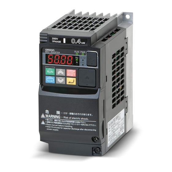
240 VAC or 480 VAC power input versions. The main features are: • 200 V and 400 V class, 0.1 to 15 kW inverters having dual rating • EzSQ (simple programming function) integrated • Built-in RS485 MODBUS RTU as standard, other FieldBus optional •... - Page 24 1-1-2 Inverter Specification Label The Omron MX2 inverters have product labels located on the right side of the housing, as pictured below. Be sure to verify that the specifications on the labels match your power source, and application safety requirements.
-
Page 25: Mx2 Inverter Specifications
1-2-1 Model-specific tables for 200 V and 400 V class inverters The following tables are specific to MX2 inverters for the 200 V and 400 V class model groups. Note that General Specifications on page 7 in this chap- ter apply to both voltage class groups. Footnotes for all specification tables fol- low the table below. - Page 26 The frequency command is the maximum frequency at 9.8 V for input voltage 0 to 10 VDC, or at 19.6 mA for input current 4 to 20 mA. If this characteristic is not satisfactory for your application, contact your Omron representative.
- Page 27 (kVA) 240 V Rated input voltage Three-phase: 200 V-15% to 240 V+10%, 50/60 Hz±5% Rated output voltage *3 Three-phase: 200 to 240 V (proportional to input voltage) Rated output current 12.0 11.0 Starting torque *6 200% at 0.5 Hz 100%: ≤50 Hz...
- Page 28 (kVA) 480 V Rated input voltage Three-phase: 380 V-15% to 480 V+10%, 50/60 Hz±5% Rated output voltage *3 Three-phase: 380 to 480 V (proportional to input voltage) Rated output current 11.1 Starting torque *6 200% at 0.5 Hz 100%: ≤50 Hz 70%: ≤50 Hz...
-
Page 29: General Specifications
Operator Up and Down keys / Value settings panel External 0 to 10 VDC (input impedance 10 k Ohms), 4 to 20 mA (input impedance signal *8 100 Ohms), Potentiometer (1 k to 2 k Ohms, 2 W) Via network... - Page 30 48 functions assignable OTQ (over/under torque threshold), UV (under-voltage), TRQ (torque limit signal), RNT (run time expired), ONT (power ON time expired), THM (ther- mal warning), BRK (brake release), BER (brake error), ZS (0Hz detection), DSE (speed deviation excessive), POK (positioning completion), ODc...
- Page 31 (derates) the inverter's maximum current output capacity. An inverter up to 4.0 kW may be mounted individually in an enclosure or side- by-side with other inverter(s) as shown below. Side-by-side mounting causes greater derating than mounting inverters separately. Graphs for either mount- ing methods are included in this section.
- Page 32 – : Need no derating Use the following derating curves to help determine the optimal carrier fre- quency setting for your inverter and find the output current derating. Be sure to use the proper curve for your particular MX2 inverter model number.
- Page 33 MX2 Inverter Specifications Section 1-2 MX2-AB004 CT (3.0 A) VT (3.5 A) output current 8 10 12 16 kH 8 10 12 14 kH Carrier frequency Carrier frequency MX2-A2004 CT (3.0 A) VT (3.5 A) 40°C individual 40°C side-by-side 40°C individual output current 40°C side-by-side...
- Page 34 VT (11.1 A) 40°C individual 40°C individual 40°C side-by-side 40°C side-by-side output current 8 10 12 16 kH 8 10 12 14 kH Carrier frequency Carrier frequency MX2-A2075 CT (33.0 A) VT (40.0 A) 40°C individual 40°C side-by-side output current...
- Page 35 MX2-A4110 CT (24.0 A) VT (31.0 A) 50°C individual output current 40°C side-by-side 8 10 12 16 kH 8 10 12 14 kH Carrier frequency Carrier frequency MX2-A2150 CT (60.0 A) VT (69.0 A) output current 50°C individual 40°C side-by-side 50°C individual...
-
Page 36: Introduction To Variable-Frequency Drives
The drive first converts incoming AC power to DC through a rectifier bridge, creating an internal DC bus voltage. Then the inverter circuit converts the DC back to AC again to power the motor. The special inverter can vary its output frequency and voltage according to the desired motor speed. - Page 37 With the free-setting torque curve feature, you can specify a series of data points that will define a custom torque curve to fit your appli- cation.
- Page 38 1-3-7 Braking In general, braking is a force that attempts to slow or stop motor rotation. So it is associated with motor deceleration, but may also occur even when the load attempts to drive the motor faster than the desired speed (overhauling). If you need the motor and load to decelerate quicker than their natural deceleration during coasting, we recommend installing a braking resistor.
- Page 39 FWD and REV commands determine the direction before the motion starts. Note The MX2 can move loads in both directions. However, it is not designed for use in servo-type applications that use a bipolar velocity signal that deter- mines direction.
-
Page 40: Frequently Asked Questions
Q. Although the MX2 inverter is a variable speed drive, can I use it in a fixed- speed application? A. Yes, sometimes an inverter can be used simply as a "soft-start" device, providing controlled acceleration and deceleration to a fixed speed. - Page 41 800V insulation for 200V class invert- ers, or 1600V insulation for 400V class. Motor size - In practice, it's better to find the right size motor for your ap- plication; then look for the inverter to match the motor.
- Page 42 Frequently Asked Questions Section 1-4...
-
Page 43: Inverter Mounting And Installation
1. Look for any damage that may have occurred during transportation. 2. Verify the contents of the box. 3. Inspect the specifications label on the side of the inverter. Make sure it matches the product part number you ordered. 2-1-2... - Page 44 Be sure to replace them afterward. Never operate the inverter with the partition removed or the front housing cover removed. The power input and motor 3-phase wiring connect to the lower row of the ter- minals. The upper row of power terminals connect to optional braking units or DC link choke.
- Page 45 (6) Optional board cover (3) Cooling fin (7) Backing plate (4) Main housing Note 3-phase 200 V/0.75 kW models come with a cooling fan. 1-phase 200 V/0.75 kW models and 3-phase 400 V/0.4 kW/0.75 kW models do not come with a cooling fan.
- Page 46 Orientation to Inverter Features Section 2-1 3-phase 200 V 3.7 kW 3-phase 400V 4.0 kW 3-phase 200 V 5.5, 7.5 kW 3-phase 400 V 5.5, 7.5 kW (1) Cooling fan cover (5) Terminal block cover (2) Cooling fan (6) Optional board cover...
- Page 47 Orientation to Inverter Features Section 2-1 3-phase 200 V 11 kW 3-phase 400 V 11, 15 kW 3-phase 200 V 15 kW (1) Cooling fan cover (5) Terminal block cover (2) Cooling fan (6) Optional board cover (3) Cooling fin...
-
Page 48: Basic System Description
If you are connecting a motor to the inverter on a test bench just to get started, that's all you may need for now. But a system can also have a variety of additional components. Some can be for noise suppression, while others may enhance the inverter's braking perfor- mance. -
Page 49: Step-By-Step Basic Installation
Make observations and check your installation. page 57 Note If the installation is in an EU country, study the EMC installation guidelines in Appendix D CE-EMC Installation Guidelines. Choosing a Mounting Location Study the following caution messages associated with mounting the inverter. - Page 50 Otherwise, there is the danger of fire. !Caution Be sure to install the inverter in a place that can bear the weight according to the specifications in the text (Chapter 1, Specifications Tables). Otherwise, it may fall and cause injury to personnel.
- Page 51 The terminal block cover is secured with one screw at the bottom right for 3.0 kW and smaller models, or with two screws on both sides for 3.7 kW and...
-
Page 52: Installation Method
2-3-3-2 Installation method Follow the removal procedure in reverse. Set the top side of the terminal block cover onto the main unit and push in the cover until you hear a "click" sound. Optional board cover 8.8.8.8. 8.8.8.8. - Page 53 MX2-A2002 MX2-A2004 122.5 MX2-A2007 145.5 Note Some inverter housing require two mounting screws, while other requires four. Be sure to use lock washers or other means to ensure screws do not loosen due to vibration. 2-φ4.5 8.8.8.8. Power Type W (mm)
- Page 54 Step-by-Step Basic Installation Section 2-3 2-φ4.5 8.8.8.8. Power Type W (mm) H (mm) D (mm) D1 (mm) 3-phase 200 V MX2-A2037 170,5 3-phase 400 V MX2-A4040...
- Page 55 Step-by-Step Basic Installation Section 2-3 2-φ6 8.8.8.8. Power Type W (mm) H (mm) D (mm) D1 (mm) 3-phase 200 V MX2-A2055 73.3 MX2-A2075 3-phase 400 V MX2-A4055 MX2-A4075...
- Page 56 Step-by-Step Basic Installation Section 2-3 2-φ7 8.8.8.8. Power Type W (mm) H (mm) D (mm) D1 (mm) 3-phase 200 V MX2-A2110 3-phase 400 V MX2-A4110 MX2-A4150...
- Page 57 Step-by-Step Basic Installation Section 2-3 8.8.8.8. Power Type W (mm) H (mm) D (mm) D1 (mm) 3-phase 200 V MX2-A2150...
- Page 58 100,000 rms symmetrical amperes, 480 volts maximum." For 400V models. !HIGH VOLTAGE Be sure to ground the unit. Otherwise, there is a danger of electric shock and/ or fire. !HIGH VOLTAGE Wiring work shall be carried out only by qualified personnel.
- Page 59 Be sure to consider the capacity of the circuit breaker to be used. Note 3 Be sure to use a larger wire gauge if power line length exceeds 66 ft. (20 m). Note 4 Use 18 AWG / 0.75 mm² wire for the alarm signal wire ([AL0], [AL1], [AL2] ter-...
- Page 60 1-phase input may be causing a trip (due to undervoltage, overcurrent, etc.) or damage to the Inverter. Do not turn on the power and then turn it off again more than once every 3 minutes. Doing so may damage the Inverter.
- Page 61 Inverter to trip or cause damage to the capacitor or surge absorber. If the cable length exceeds 20 m (particularly, with 400 V class), a surge volt- age may be generated at the motor terminal depending on stray capacitance or inductance of the cable, causing the motor to risk his isolation (depending on motor isolation class and conditions).
- Page 62 Step-by-Step Basic Installation Section 2-3 Single-phase 200 V 0.75 to 2.2 kW Three-phase 200 V 1.5, 2.2 kW Three-phase 400 V 0.4 to 3.0 kW Single-phase Three-phase RB PD/+1 P/+ N/- RB PD/+1 P/+ N/- N U/T1 V/T2 W/T3 R/L1...
- Page 63 • Single-phase 200 to 240 V 50/60 Hz(0.1 kW~2.2 kW) for MX2-AB models • Three-phase 200 to 240 V 50/60 Hz (0.1 kW~15 kW) for MX2-A2 models • Three-phase 380 to 480 V 50/60 Hz (0.4 kW~15 kW) for MX2-A4 models !Caution Be sure not to power a three-phase-only inverter with single phase power.
- Page 64 • Ground fault interrupters in the power input wiring of an inverter are not an absolute protection against electric shock. !Caution Be sure to install a fuse in each phase of the main power supply to the inverter. Otherwise, there is the danger of fire.
- Page 65 The process of motor selection is beyond the scope of this manual. However, it must be an AC induction motor with three phases. It should also come with a chassis ground lug. If the motor does not have three power input leads, stop the installation and verify the motor type.
- Page 66 This includes material over the side ven- tilation ports. !WARNING Make sure the input power to the inverter is OFF. If the drive has been powered, leave it OFF for ten minutes before continuing. Ventilation holes...
-
Page 67: Powerup Test
However, do not turn OFF power during inverter operation un- less it is an emergency. !Caution The heat sink fins will have a high temperature. Be careful not to touch them. Otherwise, there is the danger of getting burned. - Page 68 • The Hz LED will be ON. If the motor starts running unexpectedly or any other problem occurs, press the STOP key. Only if necessary should you remove power to the inverter as a remedy. Note If the inverter has been previously powered and programmed, the LEDs (other than the POWER LED) may illuminate differently than as indicated above.
-
Page 69: Using The Front Panel Keypad
(6) Monitor LED [A] Turns ON (Green) when the displayed data is current related. (7) Run command LED Turns ON (Green) when a Run command is set to the operator. (Run key is effective.) (8) 7-seg LED Shows each parameter, monitors etc. - Page 70 Using the Front Panel Keypad Section 2-5 2-5-1 Keys, Modes, and Parameters The purpose of the keypad is to provide a way to change modes and parameters. The term function applies to both monitoring modes and parameters. These are all acces- sible through function codes that are primary 4-character codes.
- Page 71 Keypad Navigation Map The MX2 Series inverter drives have many programmable functions and parameters. Chapter 3 will cover these in detail, but you need to access just a few items to perform the powerup test. The menu structure makes use of function codes and parameter codes to allow programming and monitoring with only a 4-digit display and keys and LEDs.
- Page 72 Note Keep pressing for more than 1 second leads to d001 display, regardless the display situation. But note that the display will circulates while keep pressing key because of the original function of the key. (e.g. F001 –> A001 –> b001 –> C001 –> … –> displays 50.00 after 1 second)
- Page 73 Section 2-5 2-5-3 Selecting Functions and Editing Parameters To prepare to run the motor in the powerup test, this section will show how to configure the necessary parameters: 1. Select the digital operator as the source of motor speed command (A001=02).
- Page 74 Note After completing the steps above, the Run Key Enable LED will be ON. This does not mean the motor is trying to run; it means that the RUN key is now enabled. DO NOT press the RUN key at this time – complete the parameter setup first.
- Page 75 This protection depends on using correct current rating for your motor. The level of electronic thermal setting, parameter B012, is adjustable from 20% to 100% of the inverter's rated current. A proper con- figuration will also help prevent unnecessary inverter trip events.
- Page 76 !Tip If you became lost during any of these steps, first observe the state of the PRG LED. Then study the "Keypad Navigation Map" on page 49 to determine the current state of the keypad controls and display. As long as you do not press the key, no parameter will be changed by keypad entry errors.
-
Page 77: Running The Motor
1. Verify the power LED is ON. If not, check the power connections. 2. Verify the Run Key Enable LED is ON. If it is OFF, check the A002 setting. 3. Verify the PRG LED is OFF. If it is ON, review the instructions above. - Page 78 2-5-6 Single-Digit Edit Mode If a target function code or data is far from current data, using the single-digit edit mode makes it quicker. Pressing the up key and down key at the same time leads you to go into the digit-to-digit changing mode.
- Page 79 10 seconds. You can observe this by setting the frequency F001 at about half speed before running the motor. Then press RUN, and the motor will take 5 seconds to reach a steady speed. Press the STOP key to see a 5 second deceleration to a STOP.
- Page 80 Using the Front Panel Keypad Section 2-5...
-
Page 81: Configuring Drive Parameters
- inverter are now a complex industrial automation component. And this can make a prod- uct seem difficult to use, but the goal of this chapter is to make this easier for you. -
Page 82: Using The Keypad Devices
• Run Key Enable LED - This LED is ON when the inverter is ready to respond to the Run key, OFF when the Run key is disabled. • Run Key - Press this key to run the motor (the Run Enable LED must be ON first). Parameter F004, Keypad Run Key Routing, determines whether the Run key generates a Run FWD or Run REV command. -
Page 83: Operational Modes
Run Mode and turn OFF its output to the motor. In the Trip Mode, any request to run the motor is ignored. You must clear the error by pressing the Stop/Reset switch. See 6-2 Monitoring Trip Events, History, & Conditions on page 238. - Page 84 Using the Keypad Devices Section 3-2 3-2-5 Dual Rating Selection The MX2 series inverter has Dual Rating, so that it can work in two different types of load condition, Constant torque application and Variable torque appli- b049 cation. Select parameter depending on your application.
- Page 85 Speed limit of Torque control (FW) C057 Over/under-torque level (RV,PW) P040 Speed limit of Torque control (RV) When ND is selected, following functions are not displayed in intelligent termi- nals. Intelligent input terminals Intelligent output terminals 40:TL Torque Limit Selection...
-
Page 86: D" Group: Monitoring Functions
"D" Group: Monitoring Functions You can access important parameter values with the "D" Group monitoring functions, whether the inverter is in Run Mode or Stop Mode. After selecting the function code number for the parameter you want to monitor, press the D005 Function key once to show the value on the display. - Page 87 Elapsed power-on time monitor Displays total time the inverter has been pow- – hours ered up in hours. Range is 0 to 9999 / 1000 to 9999 / 100 to 999 (10,000 to 99,900) D018 Heat sink temperature monitor Temperature of the cooling fin, range is - –...
- Page 88 • When external keypad is connected, the inverter keypad will also display error codes for inverter trip events. Use the Stop key or inverter Reset function to clear the error. Refer to 6-2-2 Error Codes on page 239 to interpret the error codes.
-
Page 89: F" Group: Main Profile Parameters
. The motor direction selec- F004 tion ( ) determines the direction of rotation as commanded only from the keypad. This setting applies to any motor profile (1st or 2nd) in use at t partic- ular time. "F" Function Defaults Mode Func. -
Page 90: A" Group: Standard Functions
Parameter sets the source selection for A002 the inverter's output frequency. Parameter selects the Run command source (for FW or RV Run commands). The default settings use the input ter- minals for Europe (EU). "A" Function Defaults Mode Func. - Page 91 The inverter also has other control sources that can temporarily override the A002 parameter setting, forcing a different Run command source. The follow- ing table lists all Run command setting methods and their relative priority ("1" is the highest priority). Priority A002 Run Command Setting Method Refer to page…...
- Page 92 Frequency calculate function Note 1: You can set the inverter output frequency with function F001 only when you have specified “02” for the frequency source setting A001. If the setting of function A001 is other than “02”, function F001 operates as the frequency command monitoring function. And by setting the frequency set in...
- Page 93 Frequency Maximum Frequency Note The "2nd motor" settings in the table in this chapter store an alternate set of parameters for a second motor. The inverter can use the 1st set or 2nd set of parameters to generate the output frequency to the motor. See "Configuring the Inverter for Multiple Motors"...
- Page 94 When the input voltage is greater than the A102 ending value, the inverter outputs the ending frequency specified by Adjusting [VR-L] characteristics - This is used when an optional operator is A161 A165 used. Refer to parameters for the details.
- Page 95 [OI] input terminals for external frequency control. When intelligent input [AT] is ON, you can set the output frequency by applying a current input signal at [OI]-[L]. When the [AT] input is OFF, you can apply a voltage input signal at A001 [O]-[L] to set the output frequency.
- Page 96 Example appli- cation: A grinding machine uses a remote potmeter for operator speed input. After a setting change, the grinder maintains a very stable speed to deliver a uniform finished surface.
- Page 97 Speed 14 A034 Speed 15 A035 Note When choosing a subset of speeds to use, always start at the top of the table, and with the least-significant bit: CF1, CF2, etc The example with eight speeds in the figure below shows how input switches configured for CF1-CF3 functions can change the motor speed in real time.
- Page 98 • When programming the multi-speed settings, be sure to press key each time and then set the next multi-speed set- ting. Note that when the key is not pressed, no data will be set. • When a multi-speed setting more than 50 Hz (60 Hz) is to be See I/O specs on page 9 and page 169.
- Page 99 Note that when the key is not pressed, no data will be set. • When a multi-speed setting more than 50Hz (60 Hz) is to be set, it is necessary to program the maximum frequency A004 high enough to allow that speed Jog Frequency - The jog speed setting is used whenever the Jog command is active.
- Page 100 Jog stop mode A038 jogging frequency to 5 Hz or less to prevent tripping To enable the Run key on the digital operator for jog input, set the value 01 A002 (terminal mode) in (Run command source). Option Terminal...
- Page 101 ) for the seven points on the V/F characteristic curve. The free V/F frequencies 1 to 7 set by this function must always be in the col- lating sequence of "1<2<3<4<5<6<7". Since all the free V/F frequencies are set to 0 Hz as default (factory setting), specify their arbitrary values (being set with free-setting V/F frequency 7).
- Page 102 Up to 1000Hz for High frequency mode (d060 set to "2") Even if the voltage higher than input is set as a free-setting V/F voltage 1 to 7, the inverter output voltage cannot exceed the inverter input voltage or that specified by the AVR voltage selection. Carefully note that selecting an inappropriate control system (V/F characteristics) may result in overcurrent during motor acceleration or deceleration or vibration of the motor or other machine driven by the inverter.
- Page 103 After the setting is done, please be sure to reset (terminal RS on/off) to recalculate the motor constant. Refrain from change the setting value suddenly (within 10%). Inverter may overvoltage trip due to the rapid change of output voltage.
- Page 104 V/f characteristic curve, – motor 01... Reduced torque (1.7) 02... Free V/F 03... Sensorless vector (SLV) A045 V/f gain Sets voltage gain of the inverter, 100. range is 20. to 100.% A245 V/f gain, 2 motor 100. a046 Voltage compensation gain for Sets voltage compensation gain 100.
- Page 105 OFF. Example 2, (above right) shows a gradually changing frequency reference, for example by analog input. In this case, there will be a DC braking period at starting because the frequency set point is lower than the value specified in...
- Page 106 "A" Group: Standard Functions Section 3-5 a057 a058 DC braking performance at start can also be set separately ( And carrier frequency of DC braking performance can also be set separately a059 "A" Function Defaults Mode Func. Name Description Units...
- Page 107 Required settings: Notes: • Do not use the [DB] input continuously or for a long time when the DC braking force setting A054 is high (depends on the motor application). • Do not use the [DB] feature for continuous or high duty cycle as a holding brake.
- Page 108 Use this function if the inverter trips because of overcurrent when starting or decelerating the motor.
-
Page 109: Pid Control
When enabled, the built-in PID loop calculates an ideal inverter output value to cause a loop feedback process variable (PV) to move closer in value to the set point (SP). The frequency command serves as the SP. The PID loop algo- rithm will read the analog input for the process variable (you specify the cur- rent or voltage input) and calculate the output. - Page 110 When enabled, the PID loop calculates the ideal output frequency to minimize the loop error. This means we no longer command the inverter to run at a par- ticular frequency, but we specify the ideal value for the process variable. That ideal value is called the setpoint, and is specified in the units of the external process variable.
- Page 111 "A" Group: Standard Functions Section 3-5 !Caution Be careful not to turn PID Clear ON and reset the integrator sum when the inverter is in Run Mode (output to motor is ON). Otherwise, this could cause the motor to decelerate rapidly, resulting in a trip.
- Page 112 "A" Group: Standard Functions Section 3-5 process results in a decreasing PV. In this case, the Loop Error = -(SP - PV). A077 to configure the error term. A077 A077 Error Freq. Error Freq. Σ Σ calculation calculation PV from process with...
- Page 113 This can be useful if the installation is subject to input voltage fluctuations. However, the inverter cannot boost its motor output to a voltage higher than the power input voltage. If you enable this feature, be sure to select the proper voltage class setting for your motor.
- Page 114 Note If the load exceeds the rating of the inverter, the acceleration time may be increased. Note If using a motor with a capacity that is one size smaller than the inverter rat- b021 ing, enable the Overload Restriction function (...
- Page 115 (and for 2nd motor settings), if you set a very rapid Acc1 or Dec1 time (less than 1.0 second), the inverter may not be able to change rates to Acc2 or Dec2 before reaching the target frequency. In that case, the inverter decreases the rate of Acc1 or Dec1 in order to achieve the second ramp to the target frequency.
- Page 116 Valid for inputs: A092, A093, A094=00 Required settings: Notes: • Function A094 selects the method for second stage acceleration. It must be set = 00 to select the input terminal method in order for the [2CH] terminal assignment to operate. 3-5-13 Accel/Decel...
- Page 117 Effective for prevent- Effective for the tension control of winding Effective for lift appli- ing the collapse of machine, to prevent cutting the object to be cation because of cargo carried by lift wound, for example. the shock less start or conveyor for and stop.
- Page 118 2 A150 acceleration 1 For use of EL-S curve be sure to use select multi-speed as frequency source to avoid nuisance change of frequency during acceleration and deceleration. 3-5-14 Additional Analog Input Settings Input Range Settings - The parameters in the following table adjust the input characteristics of the analog current input.
- Page 119 Refer to parameter A011 to A015 for analog voltage input. Analog Input Calculate Function - The inverter can mathematically combine two input sources into one value. The Calculate function can either add, sub- tract, or multiply the two selected sources. This provides the flexibility needed by various applications.
- Page 120 01... SUB (A input - B input) 02... MUL (A input * B input) Add Frequency - The inverter can add or subtract on offset value to the out- put frequency setting which is specified by A001 (will work with any of the five possible sources).
- Page 121 "A" Group: Standard Functions Section 3-5 the inputs to command the inverter output frequency, these parameters adjust the starting and ending ranges of POT, as well as the output frequency range. Related characteristic diagrams are located in "Analog Input Settings" in this chapter.
-
Page 122: B" Group: Fine Tuning Functions
Overload restriction (B021~B028) is not valid when active frequency matching is activated. If the actual power failure time is longer than the B002 set value, the inverter does not resume and the motor will coast to stop. - Page 123 Range is 1 to 3 times times age / over current trip b011 Retry wait time on over voltage Range is 0.3 to 100 sec. / over current trip Up to 1000Hz for High frequency mode (d060 set to "2")
- Page 124 If the current exceeds the level you specify, the inverter will trip and log an event (error E 05) in the history table. The inverter turns the motor output OFF when tripped. Separate settings are available for the second motor (if applicable) as shown in the following table.
- Page 125 Up to 1000Hz for High frequency mode (d060 set to "2") Up to 1000Hz for High frequency mode (d060 set to "2") When parameter B012, level of electronic thermal setting, is set to motor FLA !WARNING rating (Full Load Ampere nameplate rating), the inverter provides solid state motor overload protection at 115% of motor FLA or equivalent.
- Page 126 "C061". To output the warning signal, assign parameter "13" (THM) to one of the intel- ligent output terminals [11] to [12] (C021 to C022), or to the relay output termi- nal (C026). 3-6-4...
- Page 127 ON/OFF. When the inverter detects an overload, it must decelerate the motor to reduce the current until it is less than the threshold. You can choose the rate of decel- eration that the inverter uses to lower the output current.
- Page 128 OC suppression selection * Two option codes: – Disabled Enabled This digital input allows you to change the parameter sets of overload restric- tion. (Please refer to chapter 3 for the detailed description of the overload restriction function.) Option Terminal...
- Page 129 High level access Note Since the software lock function B031 is always accessible, this feature is not the same as password protection used in other industrial control devices. So if you want to use password function, use parameter B037 together with the B031.
- Page 130 "B" Group: Fine Tuning Functions Section 3-6 When the terminal [SFT] is turned ON, the data of all the parameters and B031 functions (except the output frequency, depending on the setting of ) is locked (prohibited from editing). When the data is locked, the keypad keys cannot edit inverter parameters.
- Page 131 The reduced voltage start function enables you to make the inverter increase the output voltage gradually when starting the motor. Set a small value for the reduced voltage start selection (b036) if you intend to increase the start torque. On the other hand, setting a small value will cause the inverter to perform full-voltage starting and to easily trip because of over- current.
- Page 132 "B" Group: Fine Tuning Functions Section 3-6 3-6-10 Display related parameters Function code display restriction: b037 – The function code display restriction allows you to arbitrarily switch the display mode or the display content on the integrated operator. "B" Function Defaults Mode Func.
- Page 133 MX2 via RS-422 port, the display is locked and shows only one parameter configured by B150. Automatic return to the initial display: b164 – 10 min. after the last key operation, display returns to the initial parameter set by b038.
- Page 134 Ex. operator com. loss action Five option codes: Trip Trip after deceleration to a stop Ignore Coasting (FRS) Decelerates to a stop Note If the power is off with displaying "000" after the set, b038 comes when power is on again.
- Page 135 1 to 4 (b041 to b044), respectively. 2. Terminal-switching mode(b040=01) In this mode, the torque limit values set in the torque limits 1 to 4 (b041 to b044) are switched from one another according to the combination of the states of torque limit switch terminals 1 and 2 (TRQ1 and TRQ2) assigned to intelligent input terminals.
- Page 136 Section 3-6 3. Analog voltage input mode(b040=02) In this mode, the torque limit value is set by a voltage applied to the control cir- cuit terminal O. The voltage range 0 to 10V corresponds to the torque limit value range 0 to 200%. A single selected torque limit is valid in all the operat- ing states.
- Page 137 Regeneration When "00" is specified for the b043 b044 torque limit selection (b040), the torque limit 1 to 4 are set Torque as shown to the bottom right. The torque limit 1 to 4 are switched by the torque limit...
- Page 138 UV level.) 2. The inverter then continues deceleration according to the value set in B053. If the DC bus voltage rises up to the set value of B052, the inverter stops deceleration to avoid OV tripping.
- Page 139 360.0 decel. controlled decel. operation. Range is 0.0 to 1000.0 B053 Deceleration time of ctrl. decel. Range is 0.01 to 3600.0 B054 Initial freq. drop of ctrl. decel. Setting of initial freq. drop. Range is 0.0 to 10.0 Hz Value is double for 400V type inverter...
- Page 140 You can also specify limit levels and a hys- teresis width individually for analog inputs O and OI. You can fix the analog input data to be applied to an arbitrary value when WCO or WCOI is output. For this purpose, specify a desired value as the operation level at O/OI disconnection (b070/b071/b072).
- Page 141 Watt-hour gain setting ( The watt-hour input gain can be set within the range 1 to 1000 in step of 1. You can clear the watt-hour data by specifying "01" for the watt-hour clearance function (b078) and pressing the Stop/Reset key. You can also clear the watt- hour data at an intelligent input terminal by assigning parameter "53"...
- Page 142 (b083); the minimum limit is 3 kHz. Note If 3 kHz or less freq. has been specified for b083, this function is disabled regardless of the setting of b089. [Remark: Above graph is for schematic concept and the profile is a subject to change reflecting the temperature test.
- Page 143 Cooling Fan Control: B092 – You can select the performance of the cooling fan (if your inverter model includes a fan). This function controls whether the cool- ing fan stops or keeps on running after the inverter stops the motor. This can result in an additional energy saving and extends fan life.
- Page 144 Note When 01 is set on b180, and key is pressed, initialization starts immedi- ately and there is not any way to restore the previous parameter setting. MX2 doesn't have a method to trigger the initialization by key action as others Omron inverter models have.
- Page 145 B088=00, can cause trip events when the inverter attempts to force the load quickly to zero speed. Note Other events can cause (or be configured to cause) a free-run stop, such as power loss (see 3-6-1 Automatic Restart Mode on page 100), or an intelligent input terminal [FRS] signal.
- Page 146 3-6-21 Brake Control Function Related The brake control function allows you to make the inverter control an external brake used for a lift or other machines. To enable this function, specify "01" (enabling the brake control function) for the Brake Control Enable (b120). This function operates as described below.
- Page 147 (b124) is invalid. In such cases, the inverter proceeds to the operation described in item (4) after the output of the brake release signal. 4. After the input of the braking confirmation signal (or the output of the brake release signal [when the BOK signal function is disabled]), the inverter waits for the Brake Wait Time for Acceleration (b122), and then starts ac- celerating the motor up to the set frequency.
- Page 148 When using the brake control function, assign the following signal functions to intelligent input and output terminals as needed. 1. To input a signal indicating that the brake is released from the external brake to the inverter, assign the braking confirmation signal (44: BOK) to one of the terminal 1~7 (C001~C007) 2.
- Page 149 Besides Dual rating selection (b049), MX2 supports two different operation modes, standard mode and high frequency IM mode. In high frequency IM mode, the max. output frequency is up to 1000 Hz. Be sure to set HD mode (b049=00) at first before switching to high frequency mode.
- Page 150 Actual inverter mode can be monitored with d060. Once high frequency mode is set, initialization can be done just by setting b084, b085, b094 and setting b180, it is not needed to set b171 . "B" Function Defaults Mode Func.
- Page 151 3-6-25 Password Function The MX2 inverter has password function to prevent from changing parameters or to hide a part of parameters. There are two passwords for b037 (Function Code Display Restriction) and b031 (Software Lock) corresponding to pass- word A and password B.
-
Page 152: C" Group: Intelligent Terminal Functions
Note Terminal [5] has the ability to be a logical input, and to be an analog input for a thermistor device when PTC function (option code 19) is assigned to that ter- minal. - Page 153 [FW]. The physical label on the terminal block connector is sim- ply 1, 2, 3, 4, 5, 6, or 7. However, schematic examples in this manual also use the terminal symbol (such as [FW]) to show the assigned option. The option codes for C011 to C017 determines the active state of the logical input (active high or active low).
- Page 154 Binary encoded speed select, Bit 3, logical 1 Bit 3 (MSB) Binary encoded speed select, Bit 3, logical 0 Jogging Inverter is in Run Mode, output to motor runs at jog parameter frequency Inverter is in Stop Mode External DC braking...
- Page 155 Symbol FWD, REV Selects the direction of motor rotation: ON = FWD. While the motor is rotating, a change of F/R will start (3-wire interface) a deceleration, followed by a change in direction Selects the direction of motor rotation: OFF = REV.
- Page 156 Maintain the position deviation data Adds the A145 (add frequency) value to the output ADD frequency enable frequency Does not add the A145 value to the output frequency F-TM Force Terminal Mode Force inverter to use input terminals for output fre-...
- Page 157 Only a parameter configured in b038 is shown All the monitors can be shown No function (input ignored) (input ignored) 3-7-3 Output Terminal Configuration The inverter provides configuration for logic (discrete) and analog outputs, shown in the table below. "C" Function Defaults Mode Func. Name...
- Page 158 The open-collector output terminal [11] and [12] defaults to normally open (active low), but you can select normally closed (active high) for the terminal in order to invert the sense of the logic. You can invert the log- ical sense of the alarm relay output as well.
- Page 159 "C" Group: Intelligent Terminal Functions Section 3-7 Output Function Summary Table - This table shows all functions for the log- ical outputs (terminals [11], [12] and [AL]) at a glance. Detailed descriptions of these functions, related parameters and settings, and example wiring dia- grams are in 4-6 Using Intelligent Output Terminals on page 198.
- Page 160 When output to motor is at the set frequency, during 5-Set frequency accel (C045) and decel (C046). When output to motor is OFF, or is not at a level of the set frequency Overload Advance When output current is more than the set threshold...
- Page 161 Symbol Starting Contact Signal Either FW or RV command is given to the inverter No FW or RV command is given to the inverter, or both are given to the inverter Heat Sink Overheat Temperature of the heat sink exceeds a specified...
- Page 162 This function is for generating an early warning logic output, without causing either a trip event or a restriction of the motor current (those effects are available on other functions). "C" Function Defaults Mode Func.
- Page 163 "A044" or "A244" is the sensorless vector control. With any other V/F charac- teristic curve selected the output of the OTQ signal is unpredictable. When using the inverter for a lift, use the OTQ signal as the trigger to stop braking. Use the frequency arrival signal as the trigger to start braking.
- Page 164 °C C111 Overload warning level 2 Sets the overload warning signal Rated current level between 0% and 200% (from 0 to two times the rated current of the inverter) Up to 1000Hz for High frequency mode (d060 set to "2")
- Page 165 (such as 3G3AX-OP05), as well as a ModBus network (for networked inverter applications). The settings cannot be edited via the net- work, in order to ensure network reliability. Refer to Appendix B ModBus Net- work Communications on page 261 for more information on controlling any monitoring your inverter from a network.
- Page 166 Scale factor of PTC input. 100.0 calibration Range is 0.0 to 200% Note When you restore factory default settings, the values will change to those listed above. Be sure to manually reconfigure the values for your application, if needed, after restoring factory defaults. 3-7-8...
- Page 167 These functions are for adjustment of analog output FM and AM. The outputs are adjusted at factory before the shipment, and therefore basically no need to adjust at the customer. But in case you need to change the gain depending on your system (i.e. analog meter specification), you can use these functions for the adjustment.
- Page 168 Select any two operands out of all intelligent output options and their operator out of AND, OR, or XOR (exclusive OR). The terminal symbol for the new out- put is [LOG]. Use C021, C022 or C026 to route the logical result to terminal [11], [12] or the relay terminals.
- Page 169 Set range is 0. to 200. (x 10ms) determination time To avoid the miss-input of the multi-speed due to the time rug, waiting time to fix the multi-speed can be set by C169. When input is detected, data is fixed...
-
Page 170: H" Group: Motor Constants Functions
The "H" Group parameters configure the inverter for the motor characteristics. You must manually set H003 and H004 values to match the motor. Parameter H006 is factory-set. If you want to reset the parameters to the factory default settings, use the procedure in 6-3 Restoring Factory Default Settings on page 245. - Page 171 *2) In the SLV modes, inverter may give out reverse to given operation com- mand in the low speed range as a nature of those controls. In case there is a specific inconvenience for example reverse rotation damages the machine,...
-
Page 172: Sensorless Vector Control
When using this function, observe the following precautions: 1. If you use the inverter to drive a motor of which the capacity is two class lower than the maximum applicable capacity of the inverter, you may not be able to obtain adequate motor characteristics. - Page 173 8. If auto-tuning with motor rotation (H001=02) is used, check the followings points. a) The motor rotates up to 80% of base frequency. Check if it is no prob- lem for the application. b) The motor should not be driven by any other external force.
- Page 174 "H" Group: Motor Constants Functions Section 3-8 10. When performing the auto-tuning with one lower size of motor, enable the overload restriction function, and set the overload restriction level to 150% of the rated current of the motor. 11. When deceleration over-voltage suppress integral time (b134) is small, auto-tuning may result in over-voltage trip.
- Page 175 If inverter is stopped during auto-tuning by stop command (by STOP key or deactivate RUN input), measured constants could remain. Be sure to execute auto-tuning again. Note 7 If auto-tuning is attempted in free V/f setting, auto-tuning will fail with error dis- play. 3-8-4 Permanent Magnet motor When PM mode is selected on b171=03 and after initialization b180=01 new motor parameters appears on the "H"...
- Page 176 Never use for transportation machine and specially for vertical loads such elevators. 3. Drive is able to control up to 50 times the motor moment of Inertia. 4. Two or more motors could not be driven with one inverter 5. Be careful not exceed the demagnetization current of the motor From functionality point of view several functions and parameters are not available when PM mode is selected, next table show which ones.
-
Page 177: P" Group: Other Parameters
(pulse train input) settings, torque command, positioning command, EzSQ and communication (CompoNet, DeviceNet, EtherCat, ProfiBus, CAN Open) related. 3-9-1 Option Card Error You can select how the inverter reacts when an error results from a built-in option card. "P" Function Defaults Mode Func. - Page 178 "P" Group: Other Parameters Section 3-9 3-9-3 Speed control Related Settings Set "15" in C027 and "00" in P003, then output frequency is controlled by single phase pulse train input to EA terminal. "P" Function Defaults Mode Func. Name Description...
- Page 179 Wire phase-A to EA terminal and phase-B to EB terminal. Since common ter- minal of EB is same as other inputs, use all the input terminals as source logic (PNP open collector or voltage output type). Voltage of EB should be 18 to 24 VDC.
- Page 180 Wire phase-A to EA terminal and direction signal to EB terminal. Both sink or source logic are available for EB terminal by changing position of the short bar. Assign EB in input terminal 7. ON input is forward and OFF input is reverse direction.
- Page 181 POK: Positioning competion Note 1 If 7/EB terminal is used (P004=01~03), set 85 (EB) in input 7 (C007). ON is forward and OFF is reverse direction. Note 2 When 2-phase pulse is used, maximum frequency of phase-A and B are dif- ferent (32kHz for A-phase, 2kHz for B-phase).
- Page 182 • In simple positioning mode, the rotation direction setting (FW or RV) of the operation command is ignored. The operation command simply functions as the signal to run or stop the motor. The motor runs in the forward direc- tion when the value of "target position" -(minus) "current position" is posi- tive, or in the reverse position when the value is negative.
- Page 183 When functions "66 (CP1)" to "68 (CP3)" are assigned to input terminal [1] to [7] (C001 to C007), you can select multistage positions 0 to 7. Preset position data 0 to 7 in P060 to P067. If no assignment is set in terminals, position com- mand will be position-0 (P060).
- Page 184 • When trigger signal of homing (70: ORG), the inverter starts homing oper- ation. When homing is completed, current position data is reset (0). • Direction of homing is specified in P069. • If homing is not operated, position at power up is regarded as home posi- tion (0). Code...
- Page 185 [5] DC braking when ORL signal OFF Home position Position Low speed (P070) 3-9-9 EzSQ User Parameter Related Settings Please refer to SECTION 4 Operations and Monitoring on page 165 for the detailed description of the function. "P" Function Defaults Mode Func.
- Page 186 "P" Group: Other Parameters Section 3-9...
-
Page 187: Operations And Monitoring
Caution Messages for Operating Procedures Before continuing, please read the following Caution messages. !Caution The heat sink fins will have a high temperature. Be careful not to touch them. Otherwise, there is the danger of getting burned. !Caution The operation of the inverter can be easily changed from low speed to high speed. - Page 188 Otherwise, it may cause injury to personnel. !WARNING If the power supply is cut OFF for a short period of time, the inverter may restart operating after the power supply recovers if the Run command is active. If a restart may pose danger to personnel, so be sure to use a lock-out circuit so that it will not restart after power recovery.
-
Page 189: Connecting To Plcs And Other Devices
(PLC) as the system controller, with several connections to the inverter. It is not possible to cover all the possible types of application in this manual. It will be necessary for you to know the electrical characteristics of the devices you want to connect to the inverter. -
Page 190: Example Wiring Diagram
The schematic diagram below provides a general example of logic connector wiring, in addition to basic power and motor wiring converted in Chapter 2. The goal of this chapter is to help you determine the proper connections for the various terminals shown below for your application needs. -
Page 191: Control Logic Signal Specifications
Control Logic Signal Specifications Section 4-3 Control Logic Signal Specifications The control logic connectors are located just behind the front housing cover. The relay contacts are just to the left of the logic connectors. Connector label- ing is shown below. RS485 comm. - Page 192 Note 1 The two terminals [L] are electrically connected together inside the inverter. Note 2 We recommend using [L] logic GND (to the right) for logic input circuits and [L] analog GND (to the left) for analog I/O circuits. Note 3 Default relay N.O./N.C.
- Page 193 Wire size for control and relay terminals Use wires within the specifications listed below. For safe wiring and reliability, it is recommended to use ferrules, but if solid or stranded wire is used, strip- ping length should be 8 mm.
-
Page 194: Intelligent Terminal Listing
Section 4-4 4-3-5 How to connect? 1. Push down the cable in the inputan orange actuating lever by a slotted screwdriver (width 2.5 mm max.). 2. Plug in the conductor making pressure. 3. To remove the wire push down the orange actuating lever by a slotted screwdriver (width 2.5 mm max.) Then pull out the cable while pressing the... -
Page 195: Table Of Contents
Rotation direction detection (phase B) 157, 197 DISP Display limitation No assign 4-4-2 Intelligent Outputs Use the following table to locate pages for intelligent output material in this chapter. Input Function Summary Table Symbol Code Function Name Page Run Signal... - Page 196 44~46 General Output 1~3 IRDY Inverter Ready Signal Forward Operation Reverse Operation Major Failure Signal Window Comparator for Analog Voltage Input 118, 221 WCOI Window Comparator for Analog Current Input 118, 221 FREF Frequency Command Source Run Command Source SETM...
-
Page 197: Using Intelligent Input Terminals
!Caution Be sure to turn OFF power to the inverter before changing the short circuit bar position. Otherwise, damage to the inverter circuitry may occur. [PLC] Terminal Wiring – The... - Page 198 +24 V supply. Each diagram shows the connection for simple switches, or for a field device with transistor outputs. Note that in the lower diagram, it is nec- essary to connect terminal [L] only when using the field device with transis- tors.
- Page 199 "Sinking Inputs, External Supply" in below wiring diagram, be sure to remove the short bar, and use a diode (*) with the external supply. This will prevent a power supply contention in case the short bar is accidentally placed in the incorrect position.
- Page 200 Except driving motor, it is possible read and write the parameters by keypad and via communication even the drive itself is not powered. By having ability inverter doesn't block the current flowing into itself when it is not powered. This may cause the closed circuit when two or more inverters are connected to common I/O wiring as shown below to result in unexpected turning the on the input.
- Page 201 [FW] and [RV] input terminal operation. !WARNING If the power is turned ON and the Run command is already active, the motor starts rotation and is dangerous! Before turning power ON, confirm that the Run command is not active.
- Page 202 When changing the state of the [SET] input terminal, the change will not take effect until the inverter is stopped. When you turn ON the [SET] input, the inverter operates per the second set of parameters. When the terminal is turned OFF, the output function returns to the original settings (first set of motor parameters).
- Page 203 B003, B088, C011 to C017 Required settings: Notes: • When you want the [FRS] terminal to be active low (normally closed logic), change the setting (C011 to C017) that corresponds to the input (C001 to C007) that is assigned the [FRS] function.
-
Page 204: External Trip
[EXT] terminal. Even if the [EXT] input is turned OFF, the inverter remains in the trip state. You must reset the inverter or cycle power to clear the error, returning the inverter to the Stop Mode. - Page 205 (none) Notes: • Note that when a USP error occurs and it is canceled by a reset from a [RS] termi- nal input, the inverter restarts running immediately. • Even when the trip state is canceled by turning the terminal [RS] ON and OFF after an under voltage protection E09 occurs, the USP function will be performed.
-
Page 206: Reset Inverter
Reset inverter The [RS] terminal causes the inverter to execute the reset operation. If the inverter is in Trip Mode, the reset cancels the Trip state. When the signal [RS] is turned ON and OFF, the inverter executes the reset operation. -
Page 207: Thermistor Thermal Protection
• The Stop/Reset key on the inverter is only operational for a few seconds after inverter powerup when a hand-held remote operator is connected to the inverter. • If the [RS] terminal is turned ON while the motor is running, the motor will be free running (coasting). - Page 208 A002 = 01 Required settings: Notes: • The STP logic is inverted. Normally the switch will be closed, so you open the switch to stop. In this way, a broken wire causes the motor to stop automatically (safe design). • When you configure the inverter for 3-wire interface control, the dedicated [FW] ter- minal is automatically disabled.
- Page 209 Confirm A001 is set to 02. • This function is not available when [JG] is in use. • The range of output frequency is 0 Hz to the value in A004 (maximum frequency setting). • This setting modifies the inverter speed from using F001 output frequency setting...
-
Page 210: Overload Restriction Source Changeover
[OPE] state takes effect. • If the [OPE] input turns ON and the digital operator gives a Run command while the inverter is already running, the inverter stops the motor. Then the digital operator can control the motor. -
Page 211: Brake Confirmation
C021~C022 Required settings: 4-5-16 LAD Cancellation This function is for canceling the set ramp time and changes the output speed immediately according to the set speed. (Please refer to chapter 3 for the detailed description of the function.) Option... -
Page 212: Add Frequency Enable
The output frequency retains its normal value C001~C007 Valid for inputs: A001, A145, A146 Required settings: Notes: • A001 may specify any source; the Add Frequency will be added to or subtracted from that value to yield output frequency value. -
Page 213: Force Terminal Mode
Using Intelligent Input Terminals Section 4-5 4-5-19 Force Terminal Mode The purpose of this intelligent input is to allow a device to force the inverter to allow control of the following two parameters via the control terminals: A001 • – Frequency source setting (... - Page 214 Clear the cumulative power data hour data Does not clear the data C001~C007 Valid for inputs: Required settings: 4-5-22 General Purpose Input (1)~(7) These functions are used with EzSQ function. Refer to a description of EzSQ for the details. Option Terminal Function State Description...
-
Page 215: Analog Command Hold
This function allows you to make the inverter hold the analog command input via the external analog input terminal when the AHD terminal is made ON. While the AHD is turned ON, the up/down function can be used based on the analog signal held by this function as reference data. - Page 216 Multistage position 6 P067 Multistage position 7 You can specify a delay to be applied at multistage position setting input, until the relevant terminal input is determined. Use this specification to prevent the application of fluctuating terminal input before it is determined.
- Page 217 Section 4-5 4-5-25 Limit signal of homing, Trigger signal of zero-return These functions are used for homing performance. One of three types of homing operations can be selected by homing mode P068 selection ( ). When a homing operation ends, the current position counter P069 is cleared (to 0).
-
Page 218: Speed/Position Changeover
(Speed control operation is switched to position control operation.) If the position setting is 0 at this time, the inverter stops the motor at that posi- tion. (Hunting may occur if a certain position loop gain value has been set.) While the SPD terminal is on, the rotating direction depends on the operation command. -
Page 219: Permission Of Run Command
Run command can be accepted of Run Run command is ignored command C001~C007 Valid for inputs: Required settings: 4-5-31 Rotation direction detection Input terminal (7) is for inputting "B pulse", which is used for detecting the rotation direction. Option Terminal Function State Description Code... -
Page 220: Using Intelligent Output Terminals
(form C – nor- mally open and normally closed contacts). The relay is assigned the alarm function by default, but you can assign it to any of the functions that the open- collector output uses. - Page 221 • [AL2] – Normally closed contact The relay itself can be configured as "normally open or closed." Parameter C036, Alarm Relay Active State, is the setting. This setting determines whether or not the relay coil is energized when its output signal is OFF: C036 •...
- Page 222 • Original signal – This example signal waveform consists of three sepa- rate pulses named "A," "B," and "C." • ...with ON delay – Pulse A is delayed by the duration of the ON delay time. Pulses B and C do not appear at the output, because they are shorter than the ON delay.
-
Page 223: Run Signal
ON. • The example circuit for terminal [11] drives a relay coil. Note the use of a diode to prevent the negative going turn-off spike generated by the coil from damaging the inverter's output transistor. - Page 224 • The output turns OFF as the output frequency moves away from the threshold, delayed by 0.5 Hz • The example circuit for terminal [11] drives a relay coil. Note the use of a diode to prevent the negative going...
- Page 225 (parameter F001) as the threshold for switching. In the figure to the right, Frequency Arrival [FA1] turns ON when the output frequency gets within Fon Hz below or Fon Hz above the target constant frequency, where Fon signal is 1% of the set maximum frequency Fon = 1% of max.
-
Page 226: Overload Advance Notice Signal
[FM] terminal (see Analog Output Operation on page 225). • The example circuit for terminal [11] drives a relay coil. Note the use of a diode to prevent the negative-going turn-off spike generated by the coil from damaging the... -
Page 227: Output Deviation For Pid Control
• The default difference value is set to 3%. To change this value, change parameter C044 (deviation level). • The example circuit for terminal [11] drives a relay coil. Note the use of a diode to prevent the negative-going turn-off spike generated by the coil from damaging the... -
Page 228: Alarm Signal
ON as long as the external control circuit has power. • When the relay output is set to normally closed, a time delay of less than 2 seconds occurs after powerup before the contact is closed. - Page 229 [AL0] and [AL1]. After powerup and short delay (< 2 seconds), the relay energizes and the alarm circuit is OFF. Then, either an inverter trip event or an inverter power loss will de-energize the relay and open the alarm circuit •...
- Page 230 "03 (SLV mode)". With any other V/F characteristic curve selection, the out- put of the OTQ signal is unpredictable. • When using the inverter for a lift, use the OTQ signal as the trigger to stop braking. Use the frequency arrival signal as the trigger to start braking.
-
Page 231: Torque Limited Signal
A044=03, b040~b044 Required settings: Notes: • The example circuit for terminal [11] drives a relay coil. Note the use of a diode to prevent the negative-going turn-off spike generated by the coil from damaging the inverter's output transistor. 4-6-13 Running Time and Power On Time Over Signal The inverter outputs the operation time expiration signal and power on time expiration signal. - Page 232 C061 Required settings: Notes: • The example circuit for terminal [11] drives a relay coil. Note the use of a diode to prevent the negative-going turn-off spike generated by the coil from damaging the inverter's output transistor. 4-6-15 External Brake Related Output Signals These signals are used with brake control function.
-
Page 233: Zero Hz Speed Detection Signal
11, 12, AL0 - AL2 C063 Required settings: Notes: • The example circuit for terminal [11] drives a relay coil. Note the use of a diode to prevent the negative-going turn-off spike generated by the coil from damaging the inverter's output transistor. - Page 234 P027 Required settings: Notes: • The example circuit for terminal [11] drives a relay coil. Note the use of a diode to prevent the negative-going turn-off spike generated by the coil from damaging the inverter's output transistor. 4-6-18 Positioning Completion Signal Inverter gives out the positioning signal when positioning performance is done.
-
Page 235: Analog Input Disconnect Detect
• The [Dc] output can indicate an analog signal disconnect when the inverter is in Stop Mode, as well as Run Mode. • The example circuit for terminal [11] drives a relay coil. Note the use of a diode to prevent the negative-going turn-off spike generated by the coil from damaging the... -
Page 236: Pid Second Stage Output
Process Variable (PV) at or near the Setpoint (SP). And, the output of the first stage is in satura- tion. A simple solution is to add a second stage, which puts an additional and constant amount of energy into the system under control. - Page 237 OFF the [FBV] output to Stage #2, since the boost is no longer needed. 4. When the PV begins decreasing, only Stage #1 is operating, and it is in the linear control range. This region is where a properly configured system will operate most often.
- Page 238 Terminal [FBV] does not provide a PID alarm function. • The example circuit for terminal [11] drives a relay coil. Note the use of a diode to prevent the negative-going turn-off spike generated by the coil from damaging the inverter's output transistor.
-
Page 239: Logic Output Function
Section 4-6 4-6-22 Logic Output Function The inverter has a built-in logic output feature. Select any two operands out of all intelligent output options except LOG1~LOG3 and their operator out of AND, OR, or XOR (exclusive OR). The terminal symbol for the new output is... - Page 240 . If the WAC signal is given out, it is recommended to replace the main PCB and control PCB. Cooling fan warning signal – If the signal is given out, check the cooling fan d022 cover for clogging. You can also monitor the state of WAF signal in...
-
Page 241: Low Load Detection Signal
C039 Valid for inputs: 11, 12, AL0 - AL2 C038, C039 Required settings: 4-6-27 General Input (1)~(3) The functions are for EzSQ. Refer to a manual of EzSQ for detailed descrip- tion. Option Terminal Function State... - Page 242 • The inverter can recognize only the operation command is given while the IRDY signal is given out • If the IRDY signal is not given out, check whether the input power supply voltage (connect to the R, S, and T terminals) is within the range of specification 4-6-29 Forward Rotation, Reverse Rotation Signals Forward Rotation signal –...
- Page 243 Valid for inputs: 11, 12, AL0 - AL2 b060~b065, b070, b071 Required settings: Notes: • Output values of ODc and OIDc are the same as those of WCO and WCOI, respectively. 4-6-32 Frequency Command Source, Run Command Source Option Terminal...
-
Page 244: Sto Performance Monitor
This function allows you to switch the inverter setting to control two different types of motors. To use this function, assign function " " to one of the input terminal and make it on or off. When 2nd motor parameters are selected, out- put signal SETM turns on. No. Codes Description No. -
Page 245: Analog Input Operation
Note If no logic input terminal is configured for the [AT] function, then inverter rec- ognizes that [AT]=OFF and MCU recognizes [O]+[OI] as analog input. In case either (O) or (OI) is to be refered, please ground the other. - Page 246 (feedback) for PID control, and simple positioning. The dedicated terminal is called "EA" and "EB". Termi- nal "EA" is a dedicated terminal, and the terminal "EB" is an intelligent termi- nal, that has to be changed by a parameter setting.
-
Page 247: Analog Output Operation
In this case you need to set . Only "EA" input terminal is to be used. 3. Simple positioning by pulse train input This is to use the pulse train input like an encoder signal. You can select three types of operation. Analog Output Operation... -
Page 248: Safe Stop Function
Safe Stop Function Section 4-9 The graph below shows the effect of the gain and offset setting. To calibrate the [AM] output for your application (analog meter), follow the steps below: 1. Run the motor at the full scale speed, or most common operating speed. -
Page 249: Inverter System Accessories
A motor control system will obviously include a motor and inverter, as well as fuses for safety. If you are connecting a motor to the inverter on a test bench just to get started, that's all you may need for now. But a fully developed sys- tem can also have a variety of additional components. -
Page 250: Component Descriptions
= 205 V, V = 203 V, V = 197 V, where VRS is R-S line voltage, VST is S-T line voltage, VTR is T-R line volt- Unbalance factor of voltage = Max. line voltage (min.) − Mean Line voltage ×... -
Page 251: Dynamic Braking
Dynamic Braking 5-3-1 Introduction • The purpose of dynamic braking is to improve the ability of the inverter to stop (decelerate) the motor and load. This becomes necessary when an application has some or all of the following characteristics: • High load inertia compared to the available motor torque •... - Page 252 • When mounting an external dynamic braking unit, set the usage ratio (b090) to 0.0 and remove the external resistors. • The cable from the external resistor to the inverter must not exceed 5 m length. • The individual wires from the resistor to the inverter must not be bundled together.
- Page 253 Dynamic Braking Section 5-3 Inverter Braking resistor unit Inverter mounted type Max. Inverter MX2@ Connectable min. (3 %ED, 10 sec max) Voltage motor resistance Ω Resist Ω 3-phase 1-phase Type AX- 0.12 2001 B001 REM00K1400-IE 0.25 2002 B002 0.55 2004...
- Page 254 Dynamic Braking Section 5-3...
-
Page 255: Troubleshooting And Maintenance
6-1-2 General Precautions and Notes • Always keep the unit clean so that dust or other foreign matter does not enter the inverter. • Take special care in regard to breaking wires or making connection mis- takes. -
Page 256: Troubleshooting Tips
Troubleshooting Section 6-1 6-1-4 Troubleshooting Tips The table below lists typical symptoms and the corresponding solution(s). 1. Inverter does not power up. Possible Cause(s) Corrective Action Power cable is incorrectly wired. Check input wiring Short bar or DCL between [P] and Install short bar or DCL between [P] and [PD] [PD] is disconnected. - Page 257 Excess load. Remove excess load. Motor is locked. Unlock the motor. 4. Inverter does not respond to changes in frequency setting from operator. Possible Cause(s) Corrective Action Incorrect frequency source is Check frequency source (A001=02).
- Page 258 Set free V/f in V/F characteristic curve selection (A044/A244=02) Overload restriction (b021) Enable overload restriction (b021=01/02/03). is disabled (00). Despite overload restriction is enabled, the inverter trips due to Overcurrent (E03). Overload restriction level Set overload restriction level (b022/b025) lower. (b022/b025) is high. Deceleration rate at overload...
- Page 259 Over voltage suppression during Enable over voltage suppression (b130=01/02). deceleration (b130) is disabled (00). In case the inverter trips due to over voltage, despite over voltage suppression is enabled. Improper overvoltage suppression Check overvoltage suppression propotional gain propotional gain (b134) or integral (b134) and integral time (b135).
-
Page 260: Monitoring Trip Events, History, & Conditions
The inverter output turns OFF, or "trips" similar to the way a circuit breaker trips due to an over-current condition. Most faults occur when the motor is running (refer to the diagram to the right). -
Page 261: Error Codes
6-2-2 Error Codes An error code will appear on the display automatically when a fault causes the inverter to trip. The following table lists the cause associated with the error. Erro... - Page 262 Option errors (error in con- These errors are reserved for the option board. nected option board, the Each option board can show the errors for a dif- meanings change upon ferent meaning .. To check the specific mean- the connected option).
- Page 263 Code Excessive speed If the motor speed rises to "maximum fre- quency (A004) x over-speed error detection level (P026)" or more, the inverter will shut off its output and display the error code shown on the right. Positioning range error...
- Page 264 Note Reset is not allowed in 10 second after trip. Note When error E08, E14 and E30 occur, reset operation by RS terminal or STOP/ RESET key is not accepted. In this case, reset by cycling power. If still same error occurs, perform initialization.
- Page 265 Monitoring Trip Events, History, & Conditions Section 6-2 Warning Warning conditions code Free setting V/f frequency 7 > Frequency upper limit (A061) Free setting V/f frequency 7 > Frequency lower limit (A062) Free setting V/f frequency 7 > Output Frequency setting (F001) Multi-speed freq.
-
Page 266: Trip History/Inverter Status
6-2-4 Trip History and Inverter Status We recommend that you first find the cause of the fault before clearing it. When a fault occurs, the inverter stores important performance data at the moment of the fault. To access the data, use the monitor function (... -
Page 267: Restoring Factory Default Settings
After initializing the inverter, use the powerup test in Chapter 2 to get the motor running again. If operation mode (std. or high fre- quency) mode is changed, inverter must be initialized to activate new mode. -
Page 268: Maintenance And Inspection
Note 1 The life of a capacitor is affected by the ambient temperature. See page 252. Note 2 Designed life of a cooling fan is.10 years. However, it is affected by the ambi- ent temperature and other environmental conditions. Note 3 The inverter must be cleaned periodically. - Page 269 4. Use a bare wire and short terminals [R, S, T, PD/+1, P/+, N/-, U, V, and W] together as shown in the diagram. 5. Connect the megger to the inverter Earth GND and to the shorted power terminals as shown.
- Page 270 3. Use a Digital Volt Meter (DVM) and set it for 1 Ω resistance range. You can check the status of the charging state of terminals [R, S, T, U, V, W, +, and –] of the inverter and the probe of the DVM by measuring the charging state.
- Page 271 Section 6-4 6-4-4 General Inverter Electrical Measurements The following table specifies how to measure key system electrical parame- ters. The diagrams on the next page show inverter-motor systems and the location of measurement points for these parameters. Parameter Circuit location of...
- Page 272 Section 6-4 The figures below show measurement locations for voltage, current, and power measurements listed in the table on the previous page. The voltage to be measured is the fundamental wave effective voltage. The power to be measured is the total effective power.
- Page 273 Inverter Output Voltage Measurement Techniques Taking voltage measurements around drives equipment requires the right equipment and a safe approach. You are working with high voltages and high- frequency switching waveforms that are not pure sinusoids. Digital voltmeters will not usually produce reliable readings for these waveforms. And, it is usu- ally risky to connect high voltage signals to oscilloscopes.
- Page 274 6-4-6 Capacitor Life Curves The DC bus inside the inverter uses a large capacitor as shown in the dia- gram below. The capacitor handles high voltage and current as it smoothes the power for use by the inverter. So, any degradation of the capacitor will affect the performance of the inverter.
-
Page 275: Warranty
Warranty Terms The warranty period under normal installation and handling conditions is two (2) years from the date of manufacture, or one (1) year from the date of instal- lation, whichever occurs first. The warranty shall cover the repair or replace- ment, at Omron's sole discretion, of ONLY the inverter that was installed. - Page 276 Warranty Section 6-5...
-
Page 277: Glossary And Bibliography
In a control system, the range of input change for which there is no percepti- ble change in the output. In PID loops, the error term may have a dead band associated with it. Deadband may or may not be desirable; it depends on the... - Page 278 The percent of time a square wave of fixed frequency is ON (high) versus OFF (low). The ratio of operating time of a device such as a motor to its resting time. This parameter usually is specified in association with the allowable ther- mal rise for the device.
- Page 279 A ratio that expresses a phase difference (timing offset) between current and voltage supplied by a power source to a load. A perfect power factor = 1.0 (no phase offset). Power factors less than one cause some energy loss in power...
- Page 280 Omron inverter model families) to rotate the force vector in the motor without the use of a shaft position sensor (angular). Benefits include an increase in torque at the lowest speed and the cost savings from the lack of a shaft posi- tion sensor.
- Page 281 A "nick-name" for the appearance of the rotor frame assembly for an AC induction motor. Stator The windings in a motor that are stationary and coupled to the power input of the motor. See also Rotor. Tachometer A signal generator usually attached to the motor shaft for the purpose of providing feedback to the speed controlling device of the motor.
-
Page 282: Bibliography
Bibliography Section A-2 Bibliography Title Author and Publisher Variable Speed Drive Fundamentals, 2nd Ed. Phipps, Clarence A. The Fairmont Press, Inc./Prentice-Hall, Inc. 1997 Electronic Variable Speed Drives Brumbach, Michael E. Delmar Publishers 1997 ISBN 0-8273-6937-9... -
Page 283: Modbus Network Communications
The network diagram below shows a series of inverters communicating with a host computer. Each inverter must have a unique address, from 1 to 32, on the network. In a typical application, a host computer or controller is the mas-... -
Page 284: Connecting The Inverter To Modbus
Terminate Network Wiring – The RS-485 wiring must be terminated at each physical end to suppress electrical reflections and help decrease transmission errors. MX2 has a built-in 200 resistor activated by a dip switch. Select termi- nation resistors that match the characteristic impedance of the network cable. - Page 285 ModBus communications. The table below lists them together. The Required column indicates which parameters must be set properly to allow communica- tions. You may need to refer to the host computer documentation in order to match some of its settings.
-
Page 286: Network Protocol Reference
B-3-2 Message Configuration: Query Slave address: • This is a number of 1 to 32 assigned to each inverter (slave). (Only the inverter having the address given as a slave address in the query can receive the query.) • When slave address "0" is specified, the query can be addressed to all inverters simultaneously. - Page 287 16 registers (in bytes) Error check: Modbus-RTU uses CRC (Cyclic Redundancy Check) for error checking. • The CRC code is 16-bit data that is generated for 8-bit blocks of arbitrary length. • The CRC code is generated by a generator polynomial CRC-16 (X16+ X15+ X2+ 1).
- Page 288 • You can check the error by the function code in the response. The function code of the exception response is the sum of the function code of the query and 80h.
- Page 289 • When receiving a broadcasting query • When detecting a transmission error in reception of a query • When the slave address set in the query is not equal to the slave address of the inverter • When a time interval between data elements constituting a message is shorter than 3.5 characters...
- Page 290 CRC-16 (low order) Note 1 Broadcasting is disabled. Note 2 When 0 or more than 31 is specified as a number of coils, error code "03h" is returned. Note 3 Data is transferred by the specified number of data bytes (data size).
- Page 291 Note 1 Broadcasting is disabled. Note 2 Data is transferred by the specified number of data bytes (data size). In this case, 6 bytes are used to return the content of three holding registers. Note 3 The PDU Register Number are addressed starting at zero. Therefore register numbered "0012h"...
- Page 292 DC-bus voltage (284V) When the Read Holding Register command cannot be executed normally, refer to the exception response. Write in Coil [05h]: This function writes data in a single coil. Coil status changes are as follows: Data Coil Status OFF to ON...
- Page 293 Write in Holding Register [06h]: This function writes data in a specified holding register. An example follows: • Write "50 Hz" as the first Multi-speed 0 (A020) in an inverter having slave address "5." • This example uses change data "500 (1F4h)" to set "50 Hz" as the data resolution of the register "1029h"...
- Page 294 Data (high order) Data (low order) Data (low order) CRC-16 (high order) CRC-16 (high order) CRC-16 (low order) CRC-16 (low order) Note 1 Broadcasting is disabled. When test subcode is for echo (00h, 00h) only and not available to the other commands.
- Page 295 The change data is a set of high-order data and low-order data. So when the size (in bytes) of data to be changed is an odd start coil number ("7"), add "1" to the data size (in bytes) to make it an even number.
- Page 296 Write in Holding Registers [10h]: This function writes data in consecutive holding registers. An example follows: • Write "3000 seconds" as the first acceleration time 1 (F002) in an inverter having a slave address "8." • This example uses change data "300000 (493E0h)" to set "3000 sec- onds"...
- Page 297 This function is to read and write data in consecutive holding registers. An example follows: • Write "50.0 Hz" as the set frequency (F001) in an inverter having a slave address "1" and then to read out the output frequency (d001).
- Page 298 CRC-16 The content of each field is explained below. The function code of the excep- tion response is the sum of the function code of the query and 80h. The exception code indicates the factor of the exception response. Function Code...
- Page 299 Registers command (10h), new data is temporary and still outside the storage element of the inverter. If power to the inverter is shut off, this new data is lost and the previous data returns. The ENTER command is used to store this new data in the storage element of the inverter.
- Page 300 Note 2 The command to change a master from 01 to 02 is issued after the data is sent from master inverter 01 to slave and silent interval plus communication wait time (C078) passed.
-
Page 301: Network Protocol Reference
Section B-3 Note 4 Please set the communication timeout as it is valid (C077=0.01~99.99). If it is disabled (C077=0.0), EzCOM function is interrupted in case the data from master inverter was not received. In case it is interrupted, please turn on/off the power or reset (reset terminal on/off). - Page 302 In case the establishment of the inverter to be assigned as master of delays and fail to receive the com- mand to change the master, the data cannot be sent from master and admin- istrative inverter time-outs.
-
Page 303: Modbus Data Listing
ModBus Data Listing B-4-1 ModBus Coil List The following tables list the primary coils for the inverter interface to the net- work. The table legend is given below. • Coil Number – The network register address offset for the coil. The coil data is a single bit (binary) value. - Page 304 Normally, this coil is turned on when the corresponding intelligent input termi- nal on the control circuit terminal block is turned on or the coil itself is set to on. In this regard, the operation of the intelligent input terminal has priority over the operation of the coil.
- Page 305 • Reg. – The network register address offset for the value. Some values have a high-byte and low-byte address. • Range – The numerical range for the network value that is sent and/or received !Tip The network values are binary integers. Since these values cannot have an embedded decimal point, for many parameters it represents the actual value (in engineering units) multiplied by a factor of 10 or 100.
- Page 306 0 to 65530 1 [time] 0012h Trip info. 1 (factor) d081 See the list of inverter trip factors below – 0013h Trip info. 1 (inverter status) See the list of inverter trip factors below – 0014h Trip info. 1 (frequency) (high) 0 to 100000 0.01[Hz]...
- Page 307 Note 1 Assume that the rated current of the inverter is "1000". Note 2 If a number not less than "1000" (100.0 seconds) is specified, the second value after the decimal point will be ignored. Note 3 0902h setting is referred for one time when following 06H command is exe-...
- Page 308 Operator connection Modbus communication error Easy sequence error (invalid instruction) Easy sequence error (invalid nesting count) Easy sequence execution error 1 Easy sequence user trip 0 to 9 50 to 59 Option error 0 to 9 60 to 69 Encoder disconnection...
- Page 309 0 to 1000000 back monitoring 1006h d004 (low) 1007h Intelligent input terminal status d005 2^0: Terminal 1 to 2^6: Terminal 7 1 bit 1008h Intelligent output terminal status d006 2^0: Terminal 11 to 2^1: Terminal 12/ 1 bit 2^2: Relay Terminal...
- Page 310 0 or "start frequency" to "maximum 0.01 [Hz] frequency" 1223h A026 (low) 1224h Multi-speed freq. 7 A027 (high) 0 or "start frequency" to "maximum 0.01 [Hz] frequency" After changing the setting, keep the time 40 ms or longer before actually give run command...
- Page 311 0 (free-running after jogging stops [disabled during operation]) 1 (deceleration and stop after jogging stops [disabled during operation]) 2 (DC braking after jogging stops [dis- abled during operation]) 3 (free-running after jogging stops [enabled during operation]) 4 (deceleration and stop after jogging...
- Page 312 1263h PV scale conversion A075 1 to 9999 0.01 1264h PV source A076 0 (input via OI), 1 (input via O), 2 (exter- – nal communication), 3 (pulse train frequency input), 10 (operation result output) 1265h Reverse PID A077 00 (disabling), 01 (enabling) –...
- Page 313 12AFh Operation-target frequency A141 0 (digital operator), 1 (keypad potenti- – selection 1 ometer), 2 (input via O), 3 (input via OI), 4 (external communication), 5 (option ), 7 (pulse train frequency input) 12B0h Operation-target frequency A142 0 (digital operator), 1 (keypad potenti- –...
- Page 314 Data code resolution 1301h Restart mode on power failure/ b001 0 (tripping), 1 (starting with 0 Hz), 2 (start- – under-voltage trip ing with matching frequency), 3 (tripping after deceleration and stopping with matching frequency), 4 (restarting with active matching frequency)
- Page 315 0. to 100. (lower limit : b060 - b062*2) (%) 1 [%] comparators O 1341h Hysteresis width of window b062 0. to 10. (lower limit : b061 - b062 / 2) (%) 1 [%] comparators O 1342h Maximum-limit level of window b063 0.
- Page 316 Initialization mode (parameters b084 0,1 (clearing the trip history), 2 (initializ- – or trip history) ing the data), 3 (clearing the trip history and initializing the data), 4 (clearing the trip history and initializing the data and EzSQ program) 1358h...
- Page 317 0 (Read/Write OK), 1 (Protected) – 13AAh to (Reserved) – – – – 13ADh 13AEh Inverter mode selection b171 0 (disabling), 1 (IM mode), 2 (High Freq. – mode), 3 (PM mode) 13AFh to (Reserved) – – – – 13B6h 13B7h Initialization trigger...
- Page 318 (CF2: Multispeed 2 setting), 4 (CF3: Mul- tispeed 3 setting), 5 (CF4: Multispeed 4 setting), 6 (JG: Jogging), 7 (DB: external DC braking), 8 (SET: Set 2nd motor data), 9 (2CH: 2-stage acceleration/decelera- tion), 11 (FRS: free-run stop), 12 (EXT:...
- Page 319 2 (FA2: set frequency overreached), 3 (OL: overload notice advance signal (1)), 4 (OD: output devi- ation for PID control), 5 (AL: alarm sig- nal), 6 (FA3: set frequency reached), 7 (OTQ: over-torque), 9 (UV: undervolt- age), 10 (TRQ: torque limited), 11...
- Page 320 (output only during constant-speed operation) 1429h Overload warning level C041 0 to 2000 0.1 [%] 142Ah Frequency arrival setting for accel. C042 (high) 0 to 40000 0.01 [Hz] 142Bh C042 (low) 142Ch Frequency arrival setting for decel. C043 (high) 0 to 40000 0.01 [Hz]...
- Page 321 – 1 (storing the frequency data) 146Ah Reset mode selection C102 0 (resetting the trip when RS is on), – 1 (resetting the trip when RS is off), 2 (enabling resetting only upon tripping [resetting when RS is on]), 3(resetting...
- Page 322 ModBus Data Listing Section B-4 Register Function name Function Monitoring and setting items Data code resolution 14ADh Multistage speed/position C169 0 to 200 determination time 14A4h to unused – – Inaccessible – 1500h...
- Page 323 1503h Motor capacity, 1st motor H003 00(0.1kW)- 15 (18.5kW) – 1504h Motor poles setting, 1st motor H004 0 (2 poles), 1 (4 poles), 2 (6 poles), – 3 (8 poles), 4 (10 poles 1505h (Reserved) – – – –...
- Page 324 PM Starting Method Select H123 (disabling) – (enabling) 158Ah PM Initial Magnet Position H131 0 to 255 – Estimation 0 V Wait Times 158Bh PM Initial Magnet Position H132 0 to 255 – Estimation Detect Wait Times 158Ch PM Initial Magnet Position H133 0 to 255 –...
- Page 325 Torque bias value P037 -200 to +200 1 [%] 1626h Torque bias polarity selection P038 0 (as indicated by the sign), 1 (depend- – ing on the operation direction), 05(Option) 1627h Speed limit for torque-controlled P039 (high) 0 to 12000 0.01 [Hz]...
- Page 326 1633h Motor poles setting for RPM P049 0 (0 pole), 1 (2 poles), 2 (4 poles), – 3 (6 poles), 4 (8 poles), 5 (10 poles), 6 (12 poles), 7 (14 poles), 8 (16 poles), 9 (18 poles), 10 (20 poles),11 (22 poles),...
- Page 327 Section B-4 Register Function name Function Monitoring and setting items Data code resolution 1673h EzSQ user parameter U (13) P113 0 to 65530 1674h EzSQ user parameter U (14) P114 0 to 65530 1675h EzSQ user parameter U (15) P115...
- Page 328 2102h Note 1 Above register (coil data 0 to 5) is consisted with 16 coil data. EzCOM com- munication (inverter to inverter) doesn't support coil, but only register is sup- porte, in case of need to access coil, please use above registers.
- Page 329 2nd motor 2106h F203 (low) 2107h to unused – – Inaccessible – 2200h (vii) List of registers (function modes for the 2nd control settings) Register Function name Function Monitoring and setting items Data code resolution 2201h Frequency source, 2nd motor...
- Page 330 Motor capacity, 2nd motor H203 00(0.1kW)- 15 (18.5kW) – 2504h Motor poles setting, 2nd motor H204 0 (2 poles), 1 (4 poles), 2 (6 poles), – 3 (8 poles), 4 (10 poles) 2505h Motor speed constant, 2nd H205 1 to 1000...
- Page 331 Monitoring and setting items Data code resolution 251Fh to (Reserved) – – – – 2524h 2525h Auto constant R1, 2nd motor H230 (high) 1 to 65530 0.001 [O] 2526h (Reserved) – – – – 2527h Auto constant R2, 2nd motor...
- Page 332 ModBus Data Listing Section B-4...
-
Page 333: Drive Parameter Setting Tables
This appendix lists the user-programmable parameters for the MX2 series inverters and the default values for European and U.S. product types. The right-most column of the tables is blank, so you can record values you have changed from the default. This involves just a few parameters for most appli- cations. - Page 334 Parameter Settings for Keypad Entry Section C-2 C-2-2 Standard Functions Note Mark "✓" in B031=10 shows the accessible parameters when B031 is set "10", high level access. "A" Group Parameters Default Setting B031=10 User Setting Func. Name (EU) Code ✕...
- Page 335 ✓ A054 DC braking force for deceleration ✓ A055 DC braking time for deceleration ✓ A056 DC braking / edge or level detection for [DB] input ✓ A057 DC braking force at start ✓ A058 DC braking time at start ✓...
- Page 336 0.00 ✓ A155 Deceleration hold time ✓ A156 PID sleep function action threshold 0.00 ✓ A157 PID sleep function action delay time 0.0 ✓ A161 [VR] input active range start 0.00 frequency ✓ A162 [VR] input active range end 0.00 frequency ✓...
- Page 337 B003 Retry wait time before motor restart ✓ B004 Instantaneous power failure / under- voltage trip alarm enable ✓ B005 Number of restarts on power failure / under-voltage trip events ✓ B007 Restart frequency threshold 0.00 ✓ B008 Restart mode on over voltage / over current ✓...
- Page 338 Current level of active freq. Rated current matching ✓ B029 Deceleration rate of active freq. matching ✓ B030 Start freq. of active freq. matching ✓ B031 Software lock mode selection ✓ B033 Motor cable length parameter ✓ B034 Run/power ON warning time ✕...
- Page 339 ✓ B145 GS input mode ✓ B150 Display ex.operator connected ✓ B160 1st parameter of Dual Monitor ✓ B161 2nd parameter of Dual Monitor ✓ B163 Freq. set in monitoring ✓ B164 Automatic return to the initial display 00...
- Page 340 Parameter Settings for Keypad Entry Section C-2 "B" Group Parameters Default Setting B031=10 User Setting Func. Name (EU) Code ✓ B165 Ex. operator com. loss action ✕ B166 Data R/W select ✕ B171 Inverter mode selection ✕ B180 Initialization trigger ✕...
- Page 341 Output [11] active state ✓ C032 Output [12] active state ✓ C036 Alarm relay active state ✓ C038 Output mode of low current detec- tion ✓ C039 Low current detection level Rated current for each inverter model ✓ C040 Output mode of overload warning ✓...
- Page 342 Parameter Settings for Keypad Entry Section C-2 "C" Group Parameters Default Setting B031=10 User Setting Func. Name (EU) Code ✓ C056 Over/under-torque level 100. (Reverse regen. mode) ✓ C057 Over/under-torque level 100. (Reverse powering mode) ✓ C058 Over/under-torque level 100.
- Page 343 Auto constant J kW dependent ✕ H234 Auto constant J, 2nd motor ✕ H050 Slip compensation P gain for V/f 0.20 control with FB ✕ H051 Slip compensation I gain for V/f con- trol with FB ✕ H102 PM motor code setting...
- Page 344 PM Initial Magnet Position Estimation Detect Times ✕ H134 PM Initial Magnet Position Estimation Voltage Gain C-2-6 Expansion Card Functions "P" parameters will be appeared when the expansion option is connected. "P" Group Parameters Default Setting B031=10 User Setting Func. Name...
- Page 345 ✕ P045 Inverter action on network comm error ✕ P046 Polled I/O output instance number ✕ P048 Inverter action on network idle mode 01 ✕ P049 Network motor poles setting for 0.00 ✓ P055 Pulse train frequency scale ✓ P056 Time constant of pulse 0.10...
- Page 346 0000 ✓ P168 Option I/F command register to write 9 0000 ✓ P169 Option I/F command register to write 10 0000 ✓ P170 Option I/F command register to read 1 0000 ✓ P171 Option I/F command register to read 2 0000 ✓...
- Page 347 Parameter Settings for Keypad Entry Section C-2 "P" Group Parameters Default Setting B031=10 User Setting Func. Name (EU) Code ✕ P181 Profibus Clear Node address ✕ P182 Profibus Map selection ✕ P190 CompoNet node address ✕ P192 DeviceNet MAC ID...
- Page 348 Parameter Settings for Keypad Entry Section C-2...
-
Page 349: Ce-Emc Installation Guidelines
You are required to satisfy the EMC directive (2004/108/EC) when using an MX2 inverter in an EU country. To satisfy the EMC directive and to comply with standard, you need to use a dedicated EMC filter suitable for each model, and follow the guidelines in this section. - Page 350 CE-EMC Installation Guidelines Section D-1 • Allow the effective shield area of these lines to remain as large as possi- ble; i.e., do not strip away the shield (screen) further away from the cable end than absolutely necessary. • With integrated systems (for example, when the adjustable frequency...
- Page 351 0.25 m from the adjustable frequency inverter. 8. Follow safety measures in the filter installation. • If using external EMC filter, ensure that the ground terminal (PE) of the fil- ter is properly connected to the ground terminal of the adjustable fre- quency inverter.
- Page 352 CE-EMC Installation Guidelines Section D-1 D-1-2 Installation for MX2 series Model 3-ph. 200 V class and 3-ph. 400 V class are the same concept for the installation. Power supply 1-ph. 200 V Metal plate (earth) The filter is a footprint type, so it is located between the inverter and the metal plate.
-
Page 353: Omron Emc Recommendations
• Frequency variation ±4% or less • Voltage distortion THD =10% or less 2. Installation measure: • Use a filter designed for MX2 inverter. Refer to the instruction of the appli- cable external EMC filter. 3. Wiring: • Shielded wire (screened cable) is required for motor wiring, and the length must be 20 meter or less. - Page 354 Omron EMC Recommendations Section D-2...
-
Page 355: Safety (Iso 13849-1)
Removing the voltage from both terminals GS1 and GS2 disables the drive output, i.e. the power supply to the motor is cut by stopping the switching of the output transistors in a safe way. EDM output is activated when GS1 and GS2 is given to the drive. -
Page 356: Periodical Check
PL=d of the inverter is to be achieved. Periodical check Since the drive stops even one of the GS1 or GS2 is interrupted, it is to be reconfirmed that there is not faiure in the path of GS1 and GS2 periodically.