Sign In
Upload
Manuals
Brands
Omron Manuals
Inverter
Q2V Series
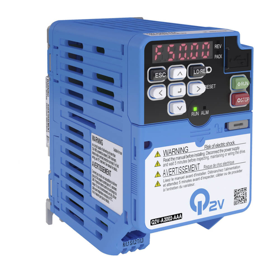
Omron Q2V Series Manuals
Manuals and User Guides for Omron Q2V Series. We have
1
Omron Q2V Series manual available for free PDF download: Technical Manual
Omron Q2V Series Technical Manual (734 pages)
Driving Quality, 200 V Class, Three-Phase: 0.1 to 22 kW, 200 V Class, Single-Phase: 0.1 to 4.0 kW, 400 V Class, Three-Phase: 0.37 to 30 kW
Brand:
Omron
| Category:
Inverter
| Size: 28.4 MB
Table of Contents
Table of Contents
3
Preface and General Precautions
13
Safety Information
14
General Safety Precautions
14
I.1 Safety Information
14
Warning Label Content and Location
16
Legal Information
17
Exclusion of Liability
17
About Registered Trademarks
17
I.2 Legal Information
17
1 Receiving
19
Model Number and Nameplate Check
20
Nameplate
20
How to Read Model Numbers
20
Features and Advantages of Control Methods
23
2 Mechanical Installation
27
Safety Precautions
28
Installation Environment
29
Installation Position and Distance
30
Moving the Drive
32
Removing/Reattaching Covers
33
Remove the
33
Reattach the
33
Remove and Reattach the Keypad
35
Remove the Keypad
35
Reattach the Keypad
35
Install the Keypad to a Control Panel or Another Device
36
Installation Methods
37
Standard Installation
37
External Heatsink
37
3 Electrical Installation
39
Safety Precautions
40
Standard Connection Diagram
42
Main Circuit Wiring
45
Motor and Main Circuit Connections
45
Configuration of Main Circuit Terminal Block
46
Main Circuit Terminal Functions
50
Wire Selection
50
Main Circuit Terminal and Motor Wiring
67
Main Circuit Terminal Block Wiring Procedure
71
Notes on Wiring the Main Circuit Terminal Block
71
3.4 Main Circuit Terminal Block Wiring Procedure
72
Control Circuit Wiring
74
Control Circuit Connection Diagram
74
Control Circuit Terminal Block Functions
75
Control Circuit Terminal Configuration
77
Wiring the Control Circuit Terminal
78
Switches and Jumpers on the Terminal Board
80
Control I/O Connections
81
Set Sinking Mode/Sourcing Mode
81
Pulse Train Output
81
Set the Input Signal for the MFAI Terminal AI2
82
Set the Output Signal for the MFAO Terminal AO
83
Switch on Termination Resistor for Modbus Communications
83
Connect the Drive to a PC
84
External Interlock
85
Braking Resistor Installation
86
Install a Braking Resistor: ERF-Type
86
Install a Braking Resistor Unit: LKEB-Type
86
Dynamic Braking Option Overload Protection
87
Drive Wiring Protection
88
Installing a Earth Leakage Circuit Breaker (RCM/RCD)
88
(Rcm/Rcd)
88
Dynamic Braking Option, Motor Protection
89
Install an Electromagnetic Contactor (MC) at the Input Side of the Drive
89
Install a Thermal Overload Relay on the Drive Output
89
Improve the Power Factor
91
Connect an AC Reactor
91
Connect a DC Reactor
91
Prevent Switching Surge
92
Decrease Noise
93
Connect a Noise Filter to the Input Side (Primary Side)
93
Connect a Noise Filter to the Output Side (Secondary Side)
93
Protect the Drive During Failures
95
Three-Phase 200 V Class
95
Single-Phase 200 V Class
95
Three-Phase 400 V Class
96
Wiring Checklist
97
Motor Application Precautions
99
Precautions for Existing Standard Motors
99
Precautions for PM Motors
100
Precautions for Specialized Motors
100
Notes on the Power Transmission Mechanism
101
4 Startup Procedure and Test Run
103
Safety Precautions
104
Component Names and Functions
105
LED Flashing Statuses
106
Keypad Mode and Menu Displays
107
Set up the Drive with Manual Setup Mode
108
Drive Mode and Programming Mode
109
Drive Mode
110
Programming Mode
110
Change Parameter Settings
110
Verify and Set the Changed Parameters (Verify Menu)
111
How to Switch between LOCAL and REMOTE
111
Start-Up Procedures
113
Flowchart A: Connect and Run the Motor with Minimal Setting Changes
113
Sub-Chart A-1: Induction Motor Auto-Tuning and Test Run Procedure
114
Sub-Chart A-2: PM Motor Auto-Tuning and Test Run Procedure
114
Sub-Chart A-3: EZ Open Loop Vector Control Test Run Procedure
115
Items to Check before Starting up the Drive
117
Check before You Energize the Drive
117
Check after You Energize the Drive
117
Keypad Operation
118
Digital Character Mapping Table
118
Show the Monitor
118
Check Modified Parameters
118
Set and View Necessary Parameters
119
Change Parameter Settings
119
Save a Backup of Parameters
120
Write Backed-Up Parameters to the Drive
121
Verify Keypad Parameters and Drive Parameters
121
Delete Parameters Backed up to the Keypad
122
Automatic Parameter Settings Optimized for Specific Applications
123
Presets)
123
Automatic Parameter Settings Optimized for Specific Applications (Application Presets)
123
Auto-Tuning
124
Auto-Tuning for Induction Motors
124
Auto-Tuning for PM Motors
125
Auto-Tuning in EZ Open Loop Vector Control Method
126
ASR and Inertia Tuning
127
Precautions before Auto-Tuning
128
Test Run
130
No-Load Test Run
130
Do a No-Load Test Run
130
Actual-Load Test Run
130
Do an Actual-Load Test Run
131
Fine Tuning During Test Runs (Adjust the Control Function)
132
V/F Control
132
Open Loop Vector Control Method
132
Fine-Tuning Open Loop Vector Control for PM Motors
134
Advanced Open Loop Vector Control Method for PM
135
EZ Open Loop Vector Control Method
135
Test Run Checklist
136
5 Standards Compliance
139
Safety Precautions
140
European Standards
142
EU Declaration of Conformity
143
CE Low Voltage Directive Compliance
147
EMC Directive
158
UL Standards
166
Area of Use
166
Wire the Main Circuit Terminal Block
166
Low Voltage Wiring for Control Circuit Terminals
177
Drive Motor Overload and Overheat Protection
177
对应中国Rohs指令
178
本产品中含有有害物质的信息
178
China Rohs Compliance
179
Information on Hazardous Substances in this Product
179
Safe Disable Input
180
Safe Disable Specifications
180
Safety Precautions
181
Safe Disable Circuit
181
Connect Safe Disable Input Contacts to Multiple Drives
182
Enabling and Disabling the Drive Output ("Safe Torque Off")
184
Safe Disable Monitor Output Function and Keypad Display
185
Validating the Safe Disable Function
186
6 Network Communications
187
Safety Precautions
188
Field Bus Network Support
189
Modbus Communications
190
Configure Master/Slave
190
Communication Specifications
190
Communication with the PLC
190
Modbus Drive Operations
192
Communications Timing
192
Message Format
193
Examples of Messages for Commands/Responses
195
Enter Command
199
Self-Diagnostics
199
Communications Data Table
200
Error Codes
211
7 Troubleshooting
213
Safety Precautions
214
Types of Faults, Minor Faults, Alarms, and Errors
216
List of Fault, Minor Fault, Alarm, and Error Codes
217
Faults
222
Minor Faults/Alarms
238
Parameter Setting Errors
247
Auto-Tuning Errors
251
Backup Function Operating Mode Display and Errors
255
Diagnosing and Resetting Faults
257
Fault Occurs Without Power Loss
257
Fault Reset Procedure
257
Troubleshooting Without Fault Display
258
Typical Problems
258
The Parameter Settings will Not Change
258
The Motor Does Not Rotate after Entering Run Command
259
The Motor Rotates in the Opposite Direction from the Run Command
260
The Motor Rotates in Only One Direction
260
The Motor Is too Hot
260
The Correct Auto-Tuning Mode Is Not Available
261
The Motor Stalls During Acceleration or Accel/Decel Time Is too Long
261
Command
262
The Motor Speed Is Not Stable When Using a PM Motor
262
There Is too Much Motor Oscillation and the Rotation Is Irregular
262
Deceleration Takes Longer than Expected When Dynamic Braking Is Enabled
262
The Load Falls When a Brake Is Applied
263
Energized
263
Residual Current Monitoring/Detection (RCM/RCD) Trips During Run
263
Motor Rotation Causes Unexpected Audible Noise from Connected Machinery
263
Motor Rotation Causes Oscillation or Hunting
263
PID Output Fault
264
The Starting Torque Is Not Sufficient
264
The Motor Rotates after the Drive Output Is Shut off
264
The Output Frequency Is Lower than the Frequency Reference
264
The Motor Is Making an Audible Noise
264
The Motor will Not Restart after a Loss of Power
265
8 Periodic Inspection and Maintenance
267
Safety Precautions
268
Inspection
270
Recommended Daily Inspection
270
Recommended Periodic Inspection
270
Maintenance
272
Replace Cooling Fans
274
Replace the Cooling Fan
274
Replace the Cooling Fan
276
Replace the Drive
279
About the Control Circuit Board
279
Storage Guidelines
283
9 Disposal
285
Safety Precautions
286
Disposal Instructions
287
WEEE Directive
288
10 Specifications
289
Safety Precautions
290
Drive Duty Modes
291
Model Specifications (Three-Phase 200 V Class)
292
Model Specifications (Single-Phase 200 V Class)
295
Model Specifications (Three-Phase 400 V Class)
296
Drive Specifications
298
Drive Derating
301
Carrier Frequency Settings and Rated Current Values
301
Derating Depending on Ambient Temperature
303
Altitude Derating
303
Drive Models and Drive Watt Loss
304
Drive Watt Loss
304
Drive Exterior and Mounting Dimensions
307
IP20/UL Open Type (Models 2001 to 2006, B001 to B004)
307
IP20/UL Open Type (Models 2010 to 2021, B006 to B018, 4001 to 4012)
308
IP20/UL Open Type (Models 2030 to 2082, 4018 to 4060)
309
10.10 Peripheral Devices and Options
311
11 Parameter List
313
How to Read the Parameter List
314
Icons and Terms that Identify Parameters and Control Modes
314
Parameter Groups
315
A: Initialization
316
A1: Initialization
316
A2: Manual Selection
317
B: APPLICATION
318
B1: OPERATION MODE SELECT
318
B2: DC INJ / SHORT CKT BRAKE
319
B3: SPEED SEARCH
319
B4: TIMER
321
B5: PID CONTROL
322
B6: DWELL FUNCTION
325
B8: ENERGY SAVING
325
C: Tuning
327
C1: Accel / Decel
327
C2: Jerk Control
327
C3: Slip Compensation
328
C4: Torque Compensation
329
C5: Asr - Speed Regulation
329
C6: Duty and Carrier
330
D: REFERENCE
331
D1: FREQUENCY REFERENCE
331
D2: REFERENCE LIMITS
332
D3: JUMP FREQUENCY
332
D4: FREQUENCY UP/DOWN
333
D6: FIELD WEAKENING / FORCING
334
D7: OFFSET FREQUENCY
334
E: Motor
335
E1: V/F Parameter Motor 1
335
E2: Motor 1 Parameters
336
E3: V/F Parameter Motor 2
336
E4: Motor 2 Parameters
337
E5: Pm Motor Settings
338
E9: Simple Vector Settings
338
F: Options
340
F1: Encoder
340
F6: Communications
341
F7: Ethernet
344
H: Terminals
348
H1: Digital Inputs
348
H2: Digital Outputs
353
H3: Analog Inputs
358
H4: Analog Outputs
360
H5: Modbus Ports
361
H6: Pulse Input Output
362
H7: Virtual Input Output
363
11.10 L: Protection
365
L1: Motor Protection
365
L2: Power Loss Ride through
366
L3: Stall Prevention
367
L4: Speed Detection
369
L5: Fault Restart
369
L6: Torque Detection
370
L7: Torque Limit
372
L8: Drive Protection
372
11.11 N: SPECIAL
375
N1: HUNTING PREVENTION
375
N2: AFR - AUTO FREQ REGULATION
375
N3: HIGHSLIP/OVEREXCITATION BRAKE
375
N5: FEED FORWARD CONTROL
376
N6: ONLINE TUNING
376
N7: SIMPLE VECTOR TUNING
376
N8: PM MOTOR CONTROL TUNING
377
Na: PM MOTOR CONTROL TUNING
380
11.12 O: KEYPAD
381
O1: KEYPAD DISPLAY
381
O2: KEYPAD OPERATION
383
O3: COPY FUNCTION
384
O4: MAINTENANCE MONITORS
384
O5: DATA LOGGER
385
11.13 Q: Q2PACK PARAMETERS
387
Q1-01 to Q8-40: Q2Pack Parameters
387
11.14 R: Q2PACK JOINTS
388
R1: Q2PACK JOINTS
388
11.15 T: Autotuning
389
T0: Tune Mode
389
T1: Induction Motor
389
T2: Pm Motor
390
T3: Asr
391
T4: Simple Vector
391
11.16 U: Monitors
392
U1: Status
392
U2: Fault
394
U3: Fault History
396
U4: Maintenance
396
U5: Pid
399
U6: Advanced
400
U8: Q2Pack Monitors
402
Parameters that Change from the Default Settings with A1-02
403
Method]
403
Parameters that Change from the Default Settings with A1-02 [Control Method]
403
Parameters that Change from the Default Settings with E3-01
407
Method Selection]
407
Parameters that Change from the Default Settings with E3-01 [M2 Control Method Selection]
407
Parameters Changed by E1-03 [V/F Pattern Selection]
408
11.20 Defaults by Drive Model and Duty Rating ND/HD
409
Three-Phase 200 V Class
409
Single-Phase 200 V Class
413
Three-Phase 400 V Class
416
11.21 Parameters Changed by PM Motor Code Selection
421
Yaskawa SMRA Series SPM Motors
421
Yaskawa SMRD Series SPM Motors
422
Yaskawa SSR1 Series IPM Motors (Derated Torque)
423
12 Parameter Details
431
A: Initialization
432
A1: Initialization
432
A2: Manual Selection
436
Notes for Elevator Applications
437
B: APPLICATION
444
B1: OPERATION MODE SELECT
444
B2: DC INJ / SHORT CKT BRAKE
454
B3: SPEED SEARCH
456
B4: TIMER
464
B5: PID CONTROL
466
B6: DWELL FUNCTION
482
B8: ENERGY SAVING
483
C: Tuning
488
C1: Accel / Decel
488
C2: Jerk Control
493
C3: Slip Compensation
494
C4: Torque Compensation
498
C5: Asr - Speed Regulation
499
C6: Duty and Carrier
504
D: REFERENCE
508
D1: FREQUENCY REFERENCE
508
D2: REFERENCE LIMITS
514
D3: JUMP FREQUENCY
514
D4: FREQUENCY UP/DOWN
516
D6: FIELD WEAKENING / FORCING
522
D7: OFFSET FREQUENCY
522
E: Motor
524
E1: V/F Parameter Motor 1
524
E2: Motor 1 Parameters
531
E3: V/F Parameter Motor 2
534
E4: Motor 2 Parameters
536
E5: Pm Motor Settings
538
E9: Simple Vector Settings
541
F: Options
544
F1: Encoder
544
F6: Communications, F7: Ethernet
546
H: Terminals
566
H1: Digital Inputs
566
MFDI Setting Values
569
H2: Digital Outputs
587
MFDO Setting Value
595
H3: Analog Inputs
608
MFAI Setting Values
613
H4: Analog Outputs
618
H5: Modbus Ports
620
H6: Pulse Input Output
624
H7: Virtual Input Output
627
L: Protection
631
L1: Motor Protection
631
L2: Power Loss Ride through
637
L3: Stall Prevention
647
L4: Speed Detection
656
L5: Fault Restart
658
L6: Torque Detection
660
L7: Torque Limit
665
L8: Drive Protection
668
N: SPECIAL
675
N1: HUNTING PREVENTION
675
N2: AFR - AUTO FREQ REGULATION
676
N3: HIGHSLIP/OVEREXCITATION BRAKE
677
N5: FEED FORWARD CONTROL
680
N6: ONLINE TUNING
683
N7: SIMPLE VECTOR TUNING
683
N8: PM MOTOR CONTROL TUNING
685
Na: PM MOTOR CONTROL TUNING
692
12.10 O: KEYPAD
694
O1: KEYPAD DISPLAY
694
O2: KEYPAD OPERATION
701
O3: COPY FUNCTION
705
O4: MAINTENANCE MONITORS
706
O5: DATA LOGGER
709
12.11 T: Autotuning
715
T0: Tune Mode
715
T1: Induction Motor
715
T2: Pm Motor
718
T3: Asr
720
T4: Simple Vector
720
13 Glossary
723
Index
724
Revision History
732
Advertisement
Advertisement
Related Products
Omron Q2A-A4004-AAA
Omron Q2A-A4009-AAA
Omron Q2A-A4007-AAA
Omron Q2A-A4018-AAA
Omron Q2A-A4060-AAA
Omron Q2A-A4075-AAA
Omron Q2A-A4208-AAA
Omron Q2A-A4168-AAA
Omron Q2A-A4250-AAA
Omron Q2A-A4453-AAA
Omron Categories
Blood Pressure Monitor
Controller
Accessories
Switch
Inverter
More Omron Manuals
Login
Sign In
OR
Sign in with Facebook
Sign in with Google
Upload manual
Upload from disk
Upload from URL