Omron RX Series User Manual
High-function general-purpose inverter
Hide thumbs
Also See for RX Series:
- User manual (414 pages) ,
- System configuration manual (19 pages) ,
- User manual (88 pages)

Related Manuals for Omron RX Series


Summary of Contents for Omron RX Series
- Page 1 High-function General-purpose Inverter RX Series Type V1 User’s Manual 3G3RX--V1 I578-E1-01...
- Page 2 OMRON. No patent liability is assumed with respect to the use of the information contained herein. Moreover, because OMRON is constantly striving to improve its high-quality products, the information contained in this manual is subject to change without notice.
-
Page 3: Introduction
Introduction Introduction Thank you for purchasing the High-function General-purpose Inverter (Model: 3G3RX--V1). This manual describes the installation and wiring methods of the 3G3RX-V1 Series Inverter, and parameter setting methods which are required for the operation, as well as troubleshooting and inspection methods. -
Page 4: Manual Configuration
Manual Configuration Manual Configuration This manual is compiled section by section for user’s convenience as follows. Section/Title Outline This section provides the features of this product, Section 1 Overview specifications, external dimensions, and part names. This section describes the installation and wiring Section 2 Design methods for this product. -
Page 5: Manual Structure
Manual Structure Manual Structure Page Structure and Symbol Icons The following page structure and symbol icons are used in this manual. Level 1 heading 2 Design Level 2 heading Removal of Each Part Level 2 heading Level 3 heading Shows which Level 3 heading 2-2-1 Removing Covers... -
Page 6: Special Information
Manual Structure Special Information Special information in this manual is classified as follows: Precautions for Safe Use Precautions on what to do and what not to do to ensure safe usage of the product. Precautions for Correct Use Precautions for Correct Use Precautions on what to do and what not to do to ensure proper operation and performance. -
Page 7: Sections In This Manual
Sections in this Manual Sections in this Manual Overview Troubleshooting Maintenance and Design Inspection Operation and Test Run Options Parameter List Appendices Basic Settings Index Vector Control Detailed Functions Communications Functions Overview of DriveProgramming High-function General-purpose Inverter 3G3RX-V1 User’s Manual (I578-E1) -
Page 8: Read And Understand This Manual
PROFITS OR COMMERCIAL LOSS IN ANY WAY CONNECTED WITH THE PRODUCTS, WHETHER SUCH CLAIM IS BASED ON CONTRACT, WARRANTY, NEGLIGENCE, OR STRICT LIABILITY. In no event shall the responsibility of OMRON for any act exceed the individual price of the product on which liability is asserted. - Page 9 Application Considerations SUITABILITY FOR USE OMRON shall not be responsible for conformity with any standards, codes, or regulations that apply to the combination of products in the customer’s application or use of the products. At the customer’s request, OMRON will provide applicable third party certification documents identifying ratings and limitations of use that apply to the products.
- Page 10 Performance data given in this manual is provided as a guide for the user in determining suitability and does not constitute a warranty. It may represent the result of OMRON’s test conditions, and the users must correlate it to actual application requirements.
-
Page 11: Safety Precautions
Safety Precautions Safety Precautions To ensure that the High-function General-purpose Inverter (Model: 3G3RX--V1) is used safely and correctly, be sure to read this Safety Precautions section and the main text before using the product. Learn all items you should know before use, regarding the equipment as well as required safety information and precautions. -
Page 12: Explanation Of Symbols
Safety Precautions Explanation of Symbols This symbol indicates a prohibited item (an item you must not do). The specific instruction is indicated using an illustration or text inside or near The symbol shown to the left indicates “disassembly prohibited.” This symbol indicates danger and caution. The specific instruction is indicated using an illustration or text inside or near The symbol shown to the left indicates “beware of electric shock.”... - Page 13 Safety Precautions WARNING Turn off the power supply and implement wiring correctly. Not doing so may result in a serious injury due to an electric shock. Wiring work must be carried out only by qualified personnel. Not doing so may result in a serious injury due to an electric shock. Do not change wiring and slide switches (SW1), put on or take off Operator and optional devices, replace cooling fans while the input power is being supplied.
-
Page 14: Precautions For Safe Use
Precautions for Safe Use Precautions for Safe Use Installation and Storage Do not store or use the product in the following places. • Locations subject to direct sunlight. • Locations subject to ambient temperature exceeding the specifications. • Locations subject to relative humidity exceeding the specifications. •... -
Page 15: Operation And Adjustment
Precautions for Safe Use Operation and Adjustment • Be sure to confirm the permissible range of motors and machines before operation because the inverter speed can be changed easily from low to high. • Provide a separate holding brake if necessary. •... -
Page 16: Precautions For Correct Use
Precautions for Correct Use Precautions for Correct Use Installation Mount the product vertically on a wall with the product’s longer sides upright. The material of the wall must be noninflammable such as a metal plate. Restart Selection Function • Do not come close to the machine when using the Restart Selection function (b001, b008) because the machine may abruptly start when stopped by an alarm. -
Page 17: Warning Label
Precautions for Correct Use Warning Label • This product bears a warning label at the following location to provide handling warnings. • Be sure to follow the instructions. The appearance differs depending on the capacity of the inverter. Warning Description High-function General-purpose Inverter 3G3RX-V1 User’s Manual (I578-E1) -
Page 18: Regulations And Standards
Regulations and Standards Regulations and Standards To export (or provide to nonresident aliens) any part of this product that falls under the category of goods (or technologies) for which an export certificate or license is mandatory according to the Foreign Exchange and Foreign Trade Control Law of Japan, an export certificate or license (or service transaction approval) according to this law is required. -
Page 19: Trademarks
Trademarks Trademarks • Windows, Windows 98, Windows XP, Windows Vista, and Windows 7 are registered trademarks of Microsoft Corporation in the USA and other countries. • DeviceNet is a registered trademark of ODVA (Open DeviceNet Vendor Association). • CompoNet is a registered trademark of ODVA (Open DeviceNet Vendor Association). •... -
Page 20: Items To Check After Unpacking
Items to Check after Unpacking Items to Check after Unpacking After unpacking, check the following items. • Is this the model you ordered? • Was there any damage sustained during shipment? Checking the Nameplate The nameplate is affixed to the product. Inverter model Input specifications Output specifications... -
Page 21: Checking The Accessories
Items to Check after Unpacking Checking the Accessories This manual is the only accessory included in the High-function General-purpose Inverter (Model: 3G3RX--V1). Mounting screws and other necessary parts must be provided by the user. High-function General-purpose Inverter 3G3RX-V1 User’s Manual (I578-E1) -
Page 22: Related Manuals
CX-Drive Operation Manual W453 LCD Digital Operator 3G3AX-OP05 User’s Manual I579 DriveProgramming User’s Manual I580 MX2/RX Series EtherCAT Communication Unit User's Manual I574 MX2/RX Series CompoNet Communications Unit User’s Manual I582 MX2/RX Series DeviceNet Communications Unit User’s Manual I581 High-function General-purpose Inverter 3G3RX-V1 User’s Manual (I578-E1) -
Page 23: Revision History
Revision History Revision History The manual revision code is a number appended to the end of the catalog number found in the bottom right-hand corner of the front and back covers. Example I578-E1-01 Cat.No. Revision code Revision code Revision date Revised Content November 2012 Original production... -
Page 24: Table Of Contents
CONTENTS CONTENTS Introduction ....................... 1 Intended Readers ............................1 Notice................................1 Manual Configuration ....................2 Manual Structure ....................... 3 Page Structure and Symbol Icons ....................... 3 Special Information ............................4 Sections in this Manual .................... 5 Read and Understand this Manual ................6 Safety Precautions .................... - Page 25 CONTENTS Appearance and Part Names ....................1-8 Specifications .......................... 1-9 1-3-1 Standard Specifications ......................1-9 1-3-2 External Dimensions......................... 1-14 Restrictions..........................1-23 Comparison with Previous Model ..................1-24 Section 2 Design Safety Information ............................3 Installation..........................2-4 2-1-1 Inverter Installation ........................2-4 2-1-2 Installation Environment ......................
- Page 26 CONTENTS 4-3-4 Group H: Motor Control Parameters ..................4-39 4-3-5 Group P: Option Parameters..................... 4-42 4-3-6 Group U: User Setting Display Parameters................4-49 Section 5 Basic Settings Parameter Display and Parameter Initialization..............5-3 5-1-1 Display Selection......................... 5-3 5-1-2 Parameter Initialization........................ 5-6 V/f Control Settings .........................
- Page 27 CONTENTS 5-12-2 Regenerative Braking Function ....................5-70 Section 6 Vector Control Overview of Vector Control..................... 6-2 Sensorless Vector Control...................... 6-4 6-2-1 Sensorless Vector Control Parameter Settings................6-4 6-2-2 0-Hz Sensorless Vector Control Parameter Settings ..............6-4 6-2-3 Auto-tuning of Motor Parameters....................6-5 6-2-4 Motor Parameter Settings ......................
- Page 28 CONTENTS Section 8 Communications Functions Communication Specifications ....................8-2 Modbus Method ........................8-6 Explanation of Each Function Code ..................8-10 Saving a Change to Holding Register (Enter Command) ..........8-20 Modbus Communication Register Number List ..............8-22 8-5-1 Coil Number List........................8-22 8-5-2 Monitor Function/Enter Command Register List ...............
- Page 29 CONTENTS 12-2-1 Specifications..........................12-5 12-2-2 External Dimensions......................... 12-7 12-2-3 Connection Examples......................12-11 12-3 Braking Resistor (Model: 3G3AX-RBA/RBB/RBC)..........12-12 12-3-1 Specifications.......................... 12-12 12-3-2 External Dimensions....................... 12-13 12-3-3 Connection Example....................... 12-15 12-4 Regenerative Braking Unit and Braking Resistor Combination Selection Table ..12-16 12-5 DC Reactor (Model: 3G3AX-DL) ................
- Page 30 CONTENTS A-2 Life Alarm Output ........................A-3 A-3 Packing Dimensions and Weight ...................A-4 A-4 Overview of Inverter Selection ....................A-5 Index High-function General-purpose Inverter 3G3RX-V1 User’s Manual (I578-E1)
-
Page 31: Overview
Overview This section provides an overview of the 3G3RX-V1 Series features, standard specifications, and external dimensions by inverter capacity. It also shows the differences of this inverter from the conventional inverter for those who use the previous model. 1-1 Overview of Functions ......... . 1-2 1-1-1 Features of 3G3RX-V1 Series Inverter . -
Page 32: Overview Of Functions
1 Overview Overview of Functions The High-function General-purpose Inverter (Model: 3G3RX--V1) is a human- and environmental-friendly inverter suitable for a variety of applications. It provides various features, such as convenient functions intended for ease of use, network support, and diverse I/O. In addition, the 3G3RX-V1 Series complies as standard with both the EC Directives and UL/cUL Standards. -
Page 33: Stall Prevention Function
1 Overview Implementation of the vector control functions With sensorless vector control, the inverter realizes a high starting torque at 200% of the motor rating in 0.3 Hz. With 0-Hz sensorless vector control, the inverter can also output a high starting torque at 150% of the motor rating in even lower frequencies. -
Page 34: Ease Of Use
1 Overview Ease of Use The 3G3RX-V1 Series Inverter contributes to the reduction of man-hours in all phases of inverter-related work: from wiring, parameter setting, operation, through to maintenance. Removable Digital Operator as standard equipment This inverter has a removable Digital Operator as standard equipment. By connecting the optional special cable, it is possible to operate the Digital Operator at hand or install it to the front face of the control panel. -
Page 35: Compliance With Safety Standards
• DeviceNet Communications Unit (Model: 3G3AX-RX-DRT-E) Environmental Consideration OMRON gives consideration to not only the inverter, but also the service life and energy efficiency of the connected motor. This inverter, as a standard product, complies with the RoHS directive and international standards to realize an environmental-friendly inverter. -
Page 36: Classes Of 3G3Rx-V1 Series Inverter
1 Overview 1-1-2 Classes of 3G3RX-V1 Series Inverter There are two voltage classes for 3G3RX-V1 Series Inverters: 3-phase 200 VAC and 3-phase 400 VAC. The applicable motor capacity is 0.4 to 132 kW. All models comply as standard with the EC Directives and UL/cUL Standards. Max. -
Page 37: Compliance With International Standards (Ec Directives And Ul/Cul Standards)
1 Overview Checking the Model 3 G 3 R X – A 2 0 5 5 – V 1 Maximum applicable motor capacity 0.4 kW 0.75 kW 1.5 kW 2.2 kW 3.7 kW 5.5 kW 7.5 kW 11 kW 15 kW 18.5 kW 22 kW 30 kW... -
Page 38: Appearance And Part Names
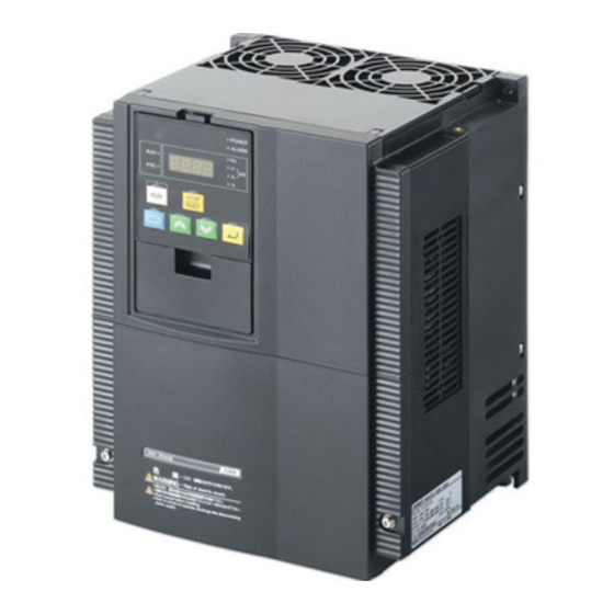
1 Overview Appearance and Part Names The following shows the front view when the product is unpacked (an example of 3G3RX-A2055-V1/A2075-V1/A2110-V1/A4055-V1/A4075-V1/A4110-V1). Digital Operator Use this to set parameters, view various monitor data, run/stop the inverter, etc. Data Display This displays the frequency reference value, output frequency, parameter set value, or other relevant data. -
Page 39: Specifications
1 Overview Specifications 1-3-1 Standard Specifications 3-phase 200-V Class CT: Heavy load mode, VT: Light load mode Model (3G3RX) Item A2004-V1 A2007-V1 A2015-V1 A2022-V1 A2037-V1 A2055-V1 A2075-V1 A2110-V1 0.75 Maximum applicable motor capacity [kW] 0.75 11.0 15.9 200 V 10.3 15.2 20.0 Rated output capacity... - Page 40 1 Overview 3-phase 400-V Class CT: Heavy load mode, VT: Light load mode Model (3G3RX) Item A4004 A4007 A4015 A4022 A4037 A4055 A4075 A4110 A4150 A4185 A4220 0.75 18.5 Maximum applicable motor capacity [kW] 0.75 18.5 13.1 17.3 22.1 26.3 33.2 400 V 11.0...
-
Page 41: Common Specifications
1 Overview Common Specifications Item Specifications IP20 (0.4 to 55 kW) Enclosure rating IP00 (75 to 132 kW) Control method Phase-to-phase sinusoidal modulation PWM Output frequency range 0.1 to 400 Hz Digital command: ±0.01% of the maximum frequency, Analog command: ±0.2% of Frequency precision the maximum frequency (25±10°C) Digital setting:... - Page 42 1 Overview Item Specifications Standard Digital Setting via keys Operator Frequency Ω 0 to 10 VDC, –10 to 10 VDC (Input impedance: 10 k ), 4 to 20 mA (Input settings External signal Ω impedance: 100 External port Setting through RS485 communications Standard Digital RUN/STOP (Forward/reverse switched via parameter settings) Forward...
- Page 43 1 Overview Item Specifications Encoder Feedback Board 3G3AX-PG01 for sensor vector control EtherCAT 3G3AX-RX-ECT Communications Unit Options CompoNet 3G3AX-RX-CRT-E Communications Unit DeviceNet 3G3AX-RX-DRT-E Communications Unit Braking resistor, AC reactor, DC reactor, Digital Operator cables, Noise filter, Other options Braking unit, etc. *1.
-
Page 44: External Dimensions
1 Overview 1-3-2 External Dimensions 3G3RX-A2004-V1/A2007-V1/A2015-V1/A2022-V1/A2037-V1/A4004-V1/ A4007-V1/A4015-V1/A4022-V1/A4037-V1 2-φ6 Mounting dimensions 4-M5 1 - 14 High-function General-purpose Inverter 3G3RX-V1 User’s Manual (I578-E1) - Page 45 1 Overview 3G3RX-A2055-V1/A2075-V1/A2110-V1/A4055-V1/A4075-V1/A4110-V1 2-φ7 24.5 Mounting dimensions 4-M6 High-function General-purpose Inverter 3G3RX-V1 User’s Manual (I578-E1) 1 - 15...
- Page 46 1 Overview 3G3RX-A2150-V1/A2185-V1/A2220-V1/A4150-V1/A4185-V1/A4220-V1 2-φ7 24.5 Mounting dimensions 4-M6 1 - 16 High-function General-purpose Inverter 3G3RX-V1 User’s Manual (I578-E1)
- Page 47 1 Overview 3G3RX-A2300-V1/A4300-V1 2-φ10 Mounting dimensions 4-M8 High-function General-purpose Inverter 3G3RX-V1 User’s Manual (I578-E1) 1 - 17...
- Page 48 1 Overview 3G3RX-A2370-V1/A2450-V1/A4370-V1/A4450-V1/A4550-V1 2-φ12 Mounting dimensions 4-M10 1 - 18 High-function General-purpose Inverter 3G3RX-V1 User’s Manual (I578-E1)
- Page 49 1 Overview 3G3RX-A2550-V1 2-φ12 Mounting dimensions 4-M10 High-function General-purpose Inverter 3G3RX-V1 User’s Manual (I578-E1) 1 - 19...
- Page 50 1 Overview 3G3RX-B4750-V1/B4900-V1 2-φ12 2-12 Mounting dimensions 4-M10 1 - 20 High-function General-purpose Inverter 3G3RX-V1 User’s Manual (I578-E1)
- Page 51 1 Overview 3G3RX-B411K-V1/B413K-V1 2-φ12 2-12 Mounting dimensions 4-M10 High-function General-purpose Inverter 3G3RX-V1 User’s Manual (I578-E1) 1 - 21...
- Page 52 1 Overview Built-in LED Digital Operator 26.5 POWER 3G3RX INVERTER ALARM STOP RESET 2-ø4 2-M3 depth 3.5 1 - 22 High-function General-purpose Inverter 3G3RX-V1 User’s Manual (I578-E1)
-
Page 53: Restrictions
1 Overview Restrictions Restriction on Light Load Mode Selecting the light load mode disables the following controls. • 0-Hz sensorless vector control • Sensor vector control Therefore, functions associated with these controls such as position and torque control functions are unavailable. -
Page 54: Comparison With Previous Model
1 Overview Comparison with Previous Model The following describes the changes and additions from the conventional 3G3RX Series. Use this information when replacing the previous model. Change in Colors of Digital Operator Keys The color scheme for Digital Operator keys was reviewed thoroughly based on a global concept that “run- and start-related keys are green”... - Page 55 1 Overview Change of Default Parameter Setting The default parameter setting of the conventional 3G3RX Series Inverter were reviewed and were changed according to the user’s usage. Some functions are enabled by default for reducing the workload of the user. The default parameter setting changed in the 3G3RX-V1 Series are shown in Section 4 Parameter List.
- Page 56 This saves time when you set the same parameter or write the same program to more than one inverter. DI Board Not Supported The 3G3RX-V1 Series Inverter does not support the OMRON DI Board (Model: 3G3AX-DI01). Do not connect the DI Board (Model: 3G3AX-DI01). 1 - 26...
- Page 57 Design This section describes the installation and wiring methods. 2-1 Installation ........... 2-4 2-1-1 Inverter Installation .
- Page 58 2 Design WARNING Turn off the power supply and implement wiring correctly. Not doing so may result in a serious injury due to an electric shock. Wiring work must be carried out only by qualified personnel. Not doing so may result in a serious injury due to an electric shock. Do not change wiring and the slide switch (SW1), install/remove the Digital Operator and optional devices, or replace the cooling fan while the input power is being supplied.
-
Page 59: Safety Information
2 Design Safety Information Installation and Storage Do not store or use the product in the following places. • Locations subject to direct sunlight. • Locations subject to ambient temperature exceeding the specifications. • Locations subject to relative humidity exceeding the specifications. •... -
Page 60: Installation
2 Design Installation 2-1-1 Inverter Installation Mount the 3G3RX-V1 Series Inverter vertically on a wall with the product’s longer sides upright. The material of the wall must be noninflammable such as a metal plate. For the mounting dimensions, refer to 1-3-2 External Dimensions on page 1-14. 2-1-2 Installation Environment Operating Environment Conditions... -
Page 61: Installation Conditions
2 Design Installation Conditions Keep the inverter clear of heating elements such as a braking resistor or reactor. If the inverter is installed in a control panel, take into consideration dimensions and ventilation to keep the ambient temperature within the range of the specifications. To allow heat dispersion from inside the inverter, provide the clearance specified in the figure below during installation. - Page 62 2 Design Loss according to the Inverter Capacity For the calculation of heat radiation from a cabinet, the following table shows the amount of heat generation (loss) according to the inverter capacity. Voltage 200-V class/400-V class Heavy load Light load Capacity Loss at 70% Loss at 100%...
- Page 63 2 Design Derating at the heavy load Voltage 200-V class 400-V class Heavy load mode Heavy load mode Capacity Max. carrier Max. carrier Derating at Necessity Derating at Necessity of [kW] frequency fc frequency fc fc = 15 kHz (10 kHz of derating fc = 15 kHz derating...
- Page 64 2 Design Derating at the light load Voltage 200-V class 400-V class Light load mode Light load mode Capacity Max. carrier Max. carrier Derating at Necessity Derating at Necessity of [kW] frequency fc frequency fc fc = 12 kHz (8 kHz of derating fc = 12 kHz derating...
-
Page 65: Removal Of Each Part
2 Design Removal of Each Part 2-2-1 Removing Covers Before wiring each terminal block, you need to remove the terminal block cover and the backing plate. In addition, to install a PG Board or communications unit, you must remove the Digital Operator, spacer cover, terminal block cover, and front cover beforehand. -
Page 66: Removing Front Cover
2 Design Removing Front Cover After removing the terminal block cover, Digital Operator, and spacer cover, loosen the front cover fixation screws. There are two front cover fixation screws, one for each side of the cover. Remove the front cover in the direction of (a) while holding it from the bottom. -
Page 67: Terminal Blocks
2 Design 2-2-2 Terminal Blocks Before wiring each terminal block, remove the terminal block cover and the backing plate. Mounting position of option board 1 Mounting position of option board 2 Charge indicator RS485 communications Control circuit terminal block terminal block Slide switch SW1 Main circuit terminal block Ground terminal with... - Page 68 2 Design Removing Control Circuit Terminal Block The following is the procedure for removing the control circuit terminal block. To reinstall it, reverse the removal procedure. Loosen the control circuit terminal block PCB guide pin PCB guide pin fixation screws. Connector (60 pins) There are two control circuit terminal block...
-
Page 69: Preparing Backing Plate
2 Design 2-2-3 Preparing Backing Plate Inverter with 22 kW or Lower Capacity When wiring cables, cut the points between the backing plate and unnecessary portions with nippers or a wire cutter, and remove. Connecting points Unnecessary portion Inverter with 30 kW or Higher Capacity ... -
Page 70: Wiring
2 Design Wiring 2-3-1 Standard Connection Diagram DC reactor Braking resistor (option) (option) MCCB P/+2 N/– R/L1 U/T1 V/T2 S/L2 T/L3 W/T3 3-phase 200 VAC 3-phase 400 VAC Short-circuit wire To wire the control circuit power supply and main circuit power supply separately, be Multi-function relay output sure to remove the J51... -
Page 71: Arrangement And Function Of Main Circuit Terminal Block
2 Design 2-3-2 Arrangement and Function of Main Circuit Terminal Block The table below shows the arrangement of the main circuit terminal block and description of each terminal. Main Circuit Terminal Block Charge indicator R/L1 S/L2 T/L3 P/+2 U/T1 V/T2 W/T3 +1–P/+2 short-circuit bar When not using the DC... -
Page 72: Arrangement And Function Of Control Circuit Terminal Block
2 Design 2-3-3 Arrangement and Function of Control Circuit Terminal Block The table below shows the arrangement of the control circuit terminal block, and description and specifications of each terminal. Control Circuit Terminal Block Terminal screw size M3 Terminal Terminal Terminal Description Specifications... - Page 73 2 Design Terminal Terminal Terminal Description Specifications symbol name This terminal outputs a signal selected from the “0 to 10 VDC Voltage Output” monitor items: Output frequency, Output Multi-function current, Output torque (with/without Max. allowable current: analog output sign), Output voltage, Input power, 2 mA (Voltage) Electronic thermal load rate, LAD...
- Page 74 2 Design Terminal Terminal Terminal Description Specifications symbol name Forward RUN When the FW signal is ON, the motor [Contact input ON command runs forward. When it is OFF, the motor condition] command terminal decelerates and stops. Voltage between each input terminal and the terminal PSC: 18 VDC or more...
- Page 75 2 Design Terminal Terminal Terminal Description Specifications symbol name Connect an external thermistor to this terminal, to cause the inverter to trip Allowable input voltage when a temperature error occurs. The range: 0 to 8 VDC terminal SC functions as the common terminal.
-
Page 76: Wiring For Main Circuit Terminals
2 Design RS-485 Communications Terminal Block The table below shows the arrangement of the RS485 communications terminal block and description of each terminal. RS– RS– Terminal Terminal Terminal name Description Specifications symbol RS485 communications Positive side send/receive signal for send/receive terminal, RS485 communications. - Page 77 2 Design Main Circuit Configuration Diagram The diagram below shows the configuration of the inverter main circuit. The function of each peripheral component is also described. Name Function (a) (b) (c) Refer to Recommended Cable Size, Wiring Power supply Device, and Crimp Terminal on page 2-26. (d) AC reactor This is used as a harmonic suppression measure.
- Page 78 2 Design Arrangement of Main Circuit Terminals The arrangement of the inverter main circuit terminals is shown below. Terminal arrangement Applicable model 3G3RX-A2004-V1 to A2037-V1 3G3RX-A4004-V1 to A4037-V1 R/L1 S/L2 T/L3 U/T1 V/T2 W/T3 Ro, To: M4 P/+2 N/– Ground terminal: M4 Others: M4 Charge indicator When not using the DC reactor,...
- Page 79 2 Design Terminal arrangement Applicable model 3G3RX-A2150-V1 to A2185-V1 3G3RX-A4150-V1 to A4220-V1 Charge indicator R/L1 S/L2 T/L3 P/+2 N/– U/T1 V/T2 W/T3 Ro, To: M4 Ground terminal: M6 Others: M6 +1–P/+2 short-circuit bar When not using the DC reactor, keep the +1–P/+2 short-circuit Ground terminal with short-circuit bar (shaded area) bar attached.
- Page 80 2 Design Terminal arrangement Applicable model 3G3RX-A2450-V1 Ro To 3G3RX-A4450-V1 Charge indicator 3G3RX-A4550-V1 R/L1 S/L2 T/L3 P/+2 N/– U/T1 V/T2 W/T3 Ro, To: M4 Ground terminal: M8 Others: M8 +1–P/+2 short-circuit bar Ground terminal with short-circuit bar (shaded area) When not using the DC reactor, for EMC filter function switching keep the +1–P/+2 short-circuit bar attached.
- Page 81 2 Design Terminal arrangement Applicable model 3G3RX-B4750-V1 Ro To 3G3RX-B4900-V1 Charge indicator 3G3RX-B411K-V1 3G3RX-B413K-V1 R/L1 S/L2 T/L3 P/+2 N/– U/T1 V/T2 W/T3 Ro, To: M4 Ground terminal: M8 Others: M10 +1–P/+2 short-circuit bar When not using the DC reactor, keep the +1–P/+2 short-circuit bar attached.
- Page 82 2 Design Recommended Cable Size, Wiring Device, and Crimp Terminal For inverter wiring, crimp terminal, and terminal screw tightening torque, refer to the table below. 200-V class External Max. Molded Power cable Heavy/ Rated Ground braking applicable Terminal case Light input Crimp...
- Page 83 2 Design External Max. Molded Power cable Heavy/ Rated Ground braking applicable Terminal case Light input Crimp Tightening cable resistor Model motor screw circuit load current terminal torque [N·m] R, S, T, U, V, W, between +1 capacity size breaker mode +1, P/+2, N/–...
- Page 84 2 Design 400-V class External Max. Molded Power cable Heavy/ Rated Ground braking applicable Terminal case Light input Crimp Tightening cable resistor Model motor screw circuit load current terminal torque [N·m] R, S, T, U, V, W, between +1 capacity size breaker...
- Page 85 2 Design External Max. Molded Power cable Heavy/ Rated Ground braking applicable Terminal case Light input Crimp Tightening cable resistor Model motor screw circuit load current terminal torque [N·m] R, S, T, U, V, W, between +1 capacity size breaker mode +1, P/+2, N/–...
- Page 86 2 Design Installing Main Circuit Terminal Block Screws For the 3G3RX-A2055-V1/A2075-V1/A4055-V1/A4075-V1, be sure to install the main circuit terminal block washers with their recessed portions aligned vertically, as shown below. Not doing so may result in a contact failure or fire. (Applicable terminals: R/L1, S/L2, T/L3, +1, P/+2, N/–, U/T1, V/T2, W/T3, RB) Terminal block screw washer Wiring for Main Power Supply Input Terminals (R/L1, S/L2, T/L3)
- Page 87 2 Design Installing earth leakage breaker When selecting the earth leakage breaker to use between the power supply and the main power supply input terminals (R/L1, S/L2, T/L3), consider the following two points. High-frequency leakage current from inverter The inverter produces a high-frequency leakage current due to its high-speed output switching. In general, a leakage current of approximately 100 mA will flow for the power cable length of 1 m per inverter.
- Page 88 2 Design Inrush current flow when the inverter power supply is turned ON When the inverter power supply is turned ON, the charging current, which is called inrush current, flows in the main circuit board capacitor. The table below shows the reference values at a power supply voltage of 240 V or 480 V when the power supply impedance is low.
- Page 89 2 Design Installing input surge absorber When using an inductive load (such as a magnetic contactor, magnetic relay, magnetic valve, solenoid, or electromagnetic brake), use a surge absorber or diode together. Installing input noise filter The inverter performs high-speed output switching, which may cause the noise flow from the inverter to power supply lines that negatively affects on peripheral equipment.
- Page 90 2 Design Harmonic Current Measures and DC/AC Reactor Wiring (+1, P/2) In recent years, there is an increasing concern about harmonic currents generated from industrial machinery. The following provides an overview of harmonics and measures against harmonics implemented in this inverter.
-
Page 91: Before Wiring
2 Design DC/AC reactor To suppress harmonic currents, use the DC (direct current) and AC (alternating current) reactors. The DC/AC reactor functions to suppress a steep change in the current. The DC reactor has a higher harmonics suppression ability, so even higher suppression ability can be expected when used in conjunction with the AC reactor. - Page 92 2 Design Effect of reactors Through the use of the DC/AC reactor, the rate of harmonic current occurrences can be reduced as shown in the table of typical examples below. Harmonic current occurrence rate [%] Measure against harmonics 11th 13th 17th 19th...
- Page 93 2 Design Precautions for connecting more than one motors to inverter’s output terminals If connecting more than one motors to the output terminals of the inverter, note the following three points. • Make sure that the rated current of the inverter is higher than the sum of the rated current values of the connected motors.
- Page 94 2 Design Measures against radio noise Besides the I/O wires, radio noise is radiated from the inverter itself. This radio noise can be reduced by installing noise filters on both the input and output sides of the inverter and by installing and shielding the inverter body in a grounded iron enclosure etc.
- Page 95 2 Design External Braking Resistor Connection Terminal (P/+2, RB)/ Regenerative Braking Unit Connection Terminal (P/+2, N/–) When driving a load with a large inertia or a vertical axis, regenerated energy is fed back to the inverter when it is decelerating or generating downward movement. If the amount of regenerative energy exceeds the amount allowable for the inverter, an overvoltage is detected.
- Page 96 2 Design • Wiring diagram for connecting one Regenerative Braking Unit (Model: 3G3AX-RBU23) Fuse Inverter MCCB R/L1 U/T1 S/L2 V/T2 Motor T/L3 W/T3 3G3AX-RBA /RBB/RBC SL1 SL2 AL1 AL2 RB P/+2 3-phase 200 V 3G3AX-RBU23 N/– 1(AL1) Master 2(AL2) MA1 MA2 Regenerative braking unit *1.
- Page 97 2 Design Precautions for Correct Use Precautions for Correct Use • Each braking resistor has alarm contact (thermal relay output) terminals as shown below. Be sure to perform wiring for these terminals. Model Alarm contact terminals 3G3AX-RBA/RBB Between terminal 1 and terminal 2 3G3AX-RBC...
- Page 98 2 Design Connection for Separating Inverter Control Circuit Power Supply from Main Power Supply If the inverter protection circuit is activated to shut off the magnetic contactor of the input power supply, the power to the inverter control circuit is also turned off, and the alarm signal cannot be retained. If the alarm signal must be retained, use control circuit power supply terminals Ro and To.
-
Page 99: Wiring For Control Circuit Terminals
2 Design 2-3-5 Wiring for Control Circuit Terminals Wiring for Control Circuit Terminals • The terminals FC and SC are insulated from each other via the input and output signal common terminals. Do not short-circuit or ground these common terminals. Do not ground these common terminals via external equipment. - Page 100 2 Design Arrangement of Control Circuit Terminal The arrangement of the control circuit terminal block is shown below. Terminal screw size M3 Tightening torque 0.7 N·m (0.8 max.) Changing Input Control Logic By factory default, the terminal FW and the multi-function input terminal are set to sink logic (NPN). To change the input control logic to source logic (PNP), remove the short-circuit bar between the terminals P24 and PSC on the control circuit terminal block, and connect it between the terminals PSC and SC.
- Page 101 2 Design Source logic When external power supply is used When inverter’s internal interface power supply is (Remove the short-circuit bar from the control used terminal block) 24 VDC Short-circuit 24 VDC 24 VDC Output unit etc. Inverter Output unit etc. Inverter ...
- Page 102 2 Design Multi-function Output Terminals and Programmable Controller Connection Sink logic Input 1 Input 2 Input common Inverter Input unit : Current-flow Source logic Input 1 Input 2 Input common Inverter Input unit : Current-flow 2 - 46 High-function General-purpose Inverter 3G3RX-V1 User’s Manual (I578-E1)
- Page 103 2 Design Precaution for Wiring Control Circuit Terminals Precaution for using more than one inverter If more than one inverter uses a common input (such as a switch), and their power-on timing is different, a sneak current will flow in the circuit as shown below. This may cause the inverters to falsely recognize the input signal is ON even if it is OFF.
- Page 104 2 Design For source logic Power ON Power ON Short-circuit wire Input Input Add a diode Power OFF Power OFF Short-circuit wire Switch OFF Switch OFF With no diode inserted, the input turns In place of short-circuit bar, insert a ON due to sneak current even when diode to prevent sneak current.
-
Page 105: Wiring For Pg Board
2 Design 2-3-6 Wiring for PG Board To use PG vector control with this inverter, you need to mount and wire the PG Board. Then, install a detector (encoder) to the motor rotating shaft and wire it to the PG Board. For the detector (encoder), use a line-driver output type encoder. -
Page 106: Input Terminals
2 Design Terminal Arrangement on PG Board The arrangement of the terminals on the PG Board is shown below. DIP Switch DIP Switch SWENC Connector to the inverter TM1 Terminal arrangement TM2 Terminal arrangement EP5 EG5 EAP EAN EBP EBN EZP EZN SAP SAN SBP SBN AP AN BP BN ... - Page 107 2 Design Output terminal Terminal Terminal Functional description Electrical specifications symbol name Encoder 5 VDC line-driver output Output pulses in a ratio 1 to 1 to encode signal input pulses. (RS-422 compliant) output Encoder power +5 VDC power supply 150 mA max.
- Page 108 2 Design Wiring for PG Board Available to allocate to PG board Inverter control terminal multi-function input Encoder signal terminals 1 to 8 5 VDC (LAD cancel) Input PCLR (Position deviation clear) terminal (Orientation) Photocoupler STAT (Pulse train position command permission) Photocoupler (Position ready) Photocoupler...
-
Page 109: Wiring For Rs485 Communications Terminals
2 Design 2-3-7 Wiring for RS485 Communications Terminals The 3G3RX-V1 Series has an RS485 communications capability that enables the inverter to communicate with an external controller from its RS485 communications terminal block on the control terminal block PCB. For the communications protocol, the inverter supports the Modbus communication and the ASCII format. -
Page 110: Wiring Method
2 Design Wiring method (1) Loosen the terminal screw with a thin flat-blade screwdriver. (2) Insert the wire through the bottom of the terminal block. (3) Tighten the terminal screw securely. Be sure to tighten the terminal screws to the tightening torque specified in the table on the previous page. -
Page 111: Wiring For Digital Operator
2 Design 2-3-8 Wiring for Digital Operator In addition to the standard Digital Operator, this inverter can be operated via the optional Digital Operator (Model: 3G3AX-OP01) or LCD Digital Operator (Model: 3G3AX-OP05). To use these options with the standard Digital Operator removed from the inverter, you need the optional Digital Operator Cable (Model: 3G3AX-OPCN1 (1 m)/3G3AX-OPCN3 (3 m)). -
Page 112: Wiring For Emergency Shutoff Function
2 Design 2-3-9 Wiring for Emergency Shutoff Function Slide Switch (SW1) Setting The built-in slide switch is used to enable or disable the emergency shutoff function. This function is disabled by factory default. For the location of the slide switch, refer to the figure below. For how to remove the control circuit terminal block, refer to Removing Control Circuit Terminal Block on page 2-12. - Page 113 2 Design Precautions for Correct Use Precautions for Correct Use • Although this function stops switching of the main element, the circuit is not electrically shut off. While the power supply is ON, do not touch the inverter terminals and power cable (e.g. motor cable).
-
Page 114: Conformance To Ec Directives
EC Directive compliant products are incorporated. This does not allow OMRON to verify the compliance under your usage conditions. Please perform the final verification on the EMC compliance of your machines or the entire system at your own responsibility. -
Page 115: Measures Against Noise
2 Design Wiring for power supply Keep the ground cable as short as possible. Place the inverter and the noise filter on the same earth (ground) plate. Always connect the power supply input terminals (R/L1, S/L2, T/L3) of the inverter to the power supply via an EMC noise filter. -
Page 116: Reference Manuals For Options
2 Design 2-3-11 Reference Manuals for Options This section provides an outline of options and peripheral equipment used with this inverter and information on their reference manual. Regenerative Braking Unit (Model: 3G3AX-RBU) This option is used in conjunction with a braking resistor to shorten the motor deceleration time. Name Catalog No. -
Page 117: Operation And Test Run
Operation and Test Run This section describes the operations of the Digital Operator and this product as well as the test run procedure. 3-1 Operation of Digital Operator ........3-4 3-1-1 Part Names and Descriptions . -
Page 118: Precautions For Safe Use
3 Operation and Test Run WARNING Do not change wiring and slide switches (SW1), put on or take off Operator and optional devices, replace cooling fans while the input power is being supplied. Doing so may result in a serious injury due to an electric shock. -
Page 119: Precautions For Correct Use
3 Operation and Test Run Precautions for Correct Use Restart Selection Function • Do not come close to the machine when using the Restart Selection function (b001, b008) because the machine may abruptly start when stopped by an alarm. • Be sure to confirm the RUN signal has turned OFF before resetting the alarm because the machine may abruptly start. -
Page 120: Operation Of Digital Operator
3 Operation and Test Run Operation of Digital Operator The Digital Operator is a display operation panel equipped as standard on the 3G3RX-V1 Series Inverter. 3-1-1 Part Names and Descriptions The table below shows the name and function of each part of the Digital Operator. Data display RUN command LED indicator Operation keys... - Page 121 3 Operation and Test Run Part Name Function Mode key When parameter is displayed: Moves to the beginning of the next function mode. When data is displayed: Cancels the setting and returns to the parameter display. In individual input mode: Moves the blinking position one digit to the left, if not located at the left end.
-
Page 122: Key Operation Method
3 Operation and Test Run 3-1-2 Key Operation Method This section explains how to use the Digital Operator keys in a typical operation (when the Display Selection is “Complete display”) and in the extended function mode U as operation examples. This operation will be the same even if you select a different setting in the Display Mode (b037), although the number of parameters that you will see on the display differs. -
Page 123: Data Display
3 Operation and Test Run Transition of Parameter Display The following figure shows how to operate the Digital Operator to reach the intended parameter display. On the parameter display Monitor Mode “d” : Moves to Data display. Data cannot be changed in Note Parameter display the monitor mode “d”. - Page 124 3 Operation and Test Run Transition of Parameter Display and Key Operation in Function Group U In the extended function mode U, you can operate the Digital Operator in the same way as in other modes. However, do not be confused although each parameter number is displayed again for the set value. Press the Enter key to enter the selected parameter number.
-
Page 125: Parameter Initialization
3 Operation and Test Run Parameter Initialization You can initialize the changed parameters and also clear the fault monitor data. As a measure to prevent inadvertent parameter initialization, the inverter is designed to force the user to set several parameters to execute initialization. For details on parameter initialization, refer to 5-1 Parameter Display and Parameter Initialization on page 5-3. - Page 126 3 Operation and Test Run Individual Input Mode (Direct Input or Selection) If the parameter number or data is far away from the current value on the display, using the individual input mode is efficient for changing the parameter data. In the individual input mode, you can change the parameter number or data by selecting and entering a value digit by digit.
- Page 127 3 Operation and Test Run (2) Change to the extended function mode. • In the left-end digit (4th digit), “d” starts blinking. • Press twice. (“A001” is displayed.) Note If you press when the left-end digit is blinking, the selected value is canceled and it returns to the display on which you pressed simultaneously.
- Page 128 3 Operation and Test Run (4) Change the 2nd digit of the extended function parameter number. • In the 2nd digit, “0” is blinking. • Press twice. (“A021” is displayed.) • In the 2nd digit, “2” is blinking. • Press to enter the value blinking in the digit.
- Page 129 3 Operation and Test Run (6) The extended function parameter number setting is completed. • The parameter number “A029” is selected. Precautions for Correct Use Precautions for Correct Use If the set parameter number is not listed in the Parameter List, or if the parameter number is hidden in the Display Selection setting, “A”...
- Page 130 3 Operation and Test Run Changes in Operation Method from Previous Model For the 3G3RX-V1, the operation method was changed from the conventional 3G3RX Series. The following table shows the changes and simplified operation method according to the 3G3MX2 Series. ...
-
Page 131: Overview Of Lcd Digital Operator
3 Operation and Test Run Overview of LCD Digital Operator The LCD Digital Operator (Model: 3G3AX-OP05) is an optional Digital Operator with a 5-line LCD screen. This LCD Digital Operator is newly supported in the 3G3RX-V1 Series and cannot be used with the previous model. -
Page 132: Connections And Functions Of Cx-Drive
The inverter/Servo support tool CX-Drive is support software to edit the inverter parameter settings. Installing the OMRON CX-One software on your PC also installs the CX-Drive simultaneously. The 3G3RX-V1 Series Inverter is supported in the following or higher versions of the CX-Drive product: •... - Page 133 3 Operation and Test Run CX-Drive Connection Procedure There are two methods to connect the CX-Drive with the inverter. The step-by-step procedure for each method is provided below. Connecting by registering inverter connection method beforehand Create a new inverter project, set the connecting method, and connect with the inverter. Follow the steps below.
- Page 134 3 Operation and Test Run In the [New Drive] window, set the type of connection to the inverter. Under [Connection Type], select [Direct] and click the [Settings] button to the right. On the [Driver] tab, set the Port Selection to the port name of the computer on which the CX-Drive is installed.
- Page 135 3 Operation and Test Run On the [Autodetect] tab, under [Drive Type Selection], check the [Inverter] box. Then, under [Connection Type Selection], check the [Direct] box and click the [Advanced Options: Direct] button to the right. Additional Information For the reduction of the automatic search time, deselect unnecessary check boxes to narrow down the scope of autodetection.
-
Page 136: Outline Of Cx-Drive
3 Operation and Test Run 3-3-2 Outline of CX-Drive The Inverter/Servo support tool CX-Drive enables you to edit inverter parameters and monitor the inverter status. This section provides a functional outline of CX-Drive. Screen Structure of CX-Drive The screen structure of the CX-Drive is as shown below. The workspace shows a list of registered drive projects. - Page 137 3 Operation and Test Run Editing Device Parameters Using CX-Drive Double-clicking [Parameter Editor] in the project opens a window in which all inverter parameters are listed (in ascending order). You can edit inverter parameters in this window. To upload/download inverter parameters, use the [Transfer] buttons in the toolbar. •...
- Page 138 3 Operation and Test Run Status Function of CX-Drive Open the Status folder in the project and double-click the status information. The window corresponding to the selected status information opens. Status icon category Description Displays the current ON/OFF status information, including the input [Digital Inputs] function settings for the selected inverter.
- Page 139 3 Operation and Test Run Monitor Function of CX-Drive Open the Monitor folder in the project and double-click Real Time Trace. The Real Time Trance window opens, in which you can monitor the operation status of the inverter. • Up to 8 signals can be traced. •...
-
Page 140: Flow Of Test Run
3 Operation and Test Run Flow of Test Run Perform a test run of the inverter according to the following flow. Item Description Reference Installation Install the inverter according to the installation conditions. Section 2, Wiring and Connect the inverter to the power supply and peripheral equipment. Section 2, connections Power-on... -
Page 141: Test Run Procedure
3 Operation and Test Run Test Run Procedure The following describes the test run procedure. Installation Check that the inverter meets the installation conditions. For details on installing the inverter, refer to 2-1 Installation on page 2-4. Wiring and Connections Select peripheral equipment according to the specifications and wire the cables securely. - Page 142 3 Operation and Test Run Display Status Checks If no problem is found at power-on, the display status will be as follows. Name Display status POWER LED ALARM LED Not lit RUN LED Not lit (Lit during RUN) RUN command LED indicator Data display LED (Hz) Data display Displays d001 setting.
-
Page 143: Parameter Setting
3 Operation and Test Run Precautions for Correct Use Precautions for Correct Use • The following parameters are not initialized: the settings of the DriveProgramming User Parameters U00 to U31 (P100 to P131), Total RUN Time Monitor (d016), Total Power ON Time Monitor (d017), Initialization Data Selection (b085), Heavy Load/Light Load Selection (b049), Thermistor Adjustment (C085), and analog adjustment parameters (C081 to C083, C121 to C123). -
Page 144: No-Load Run
3 Operation and Test Run No-load Run Rotate the motor with no-load (in a state not connected to the mechanical system) via the Digital Operator. Forward/reverse rotation via Digital Operator Follow the steps below to run the motor in the forward or reverse rotation. (1) Set the Output Frequency Setting/Monitor (F001). -
Page 145: Load Run
3 Operation and Test Run Load Run If no problem is found during no-load run, connect the mechanical system and run the inverter with load via the Digital Operator. Mechanical system connection Make sure that the motor has stopped completely before connecting the mechanical system. Then, connect the mechanical system with the motor shaft securely to prevent the screws from loosening. - Page 146 3 Operation and Test Run 3 - 30 High-function General-purpose Inverter 3G3RX-V1 User’s Manual (I578-E1)
-
Page 147: Parameter List
Parameter List This section describes the parameters used with this inverter. 4-1 Monitor Mode ..........4-2 4-1-1 Group d . -
Page 148: Monitor Mode
4 Parameter List Monitor Mode The inverter by default displays the content of the parameter d001at power-on. To monitor the desired parameter, change the setting in the Initial Screen Selection (b038). 4-1-1 Group d Changes during Parameter Default operation Function name Monitor or data range Unit Page... - Page 149 4 Parameter List Changes during Parameter Default operation Function name Monitor or data range Unit Page data Normal b031 = 10 d014 Input Power 0.0 to 999.9 – – – Monitor d015 Integrated Power 0. to 9999. – – – Monitor 1000 to 9999 (10000 to 99990)
- Page 150 4 Parameter List Changes during Parameter Default operation Function name Monitor or data range Unit Page data Normal b031 = 10 Current Time mm/dd hh: mm – – – – 7-11 d031 Monitor (Month/Day and Hours/Minutes, 12 characters) d060 Inverter Mode Displays currently set mode –...
-
Page 151: Basic Function Mode
4 Parameter List Basic Function Mode The table below lists the basic function mode parameters. 4-2-1 Group F: Basic Function Parameters Changes during Parameter Default operation Function name Monitor or data range Unit Page data Normal b031 = 10 F001 Output Frequency 0.0/Starting frequency to –... -
Page 152: Extended Function Mode
4 Parameter List Extended Function Mode In the extended function mode, inverter parameters are categorized in five groups: A, b, C, H, and P. This section provides the parameter list for each group. Note that the parameters displayed on the Digital Operator depend on the setting in the Display Selection (b037). -
Page 153: Group A: Standard Function Parameters
4 Parameter List 4-3-1 Group A: Standard Function Parameters Changes during Parameter Default operation Function name Monitor or data range Unit Page data Normal b031 = 10 A001 Frequency 00: Digital Operator (Volume Disabled Disabled – 7-17 Reference adjuster) Selection (Enabled when 3G3AX-OP01 is connected) 01: Control circuit terminal block... - Page 154 4 Parameter List Changes during Parameter Default operation Function name Monitor or data range Unit Page data Normal b031 = 10 A005 FV/FI Selection 00: Switching between FV Disabled Disabled – 7-21 (Voltage) and FI (Current) via terminal AT 02: Switching between FV and volume adjuster via terminal AT 03: Switching between FI and volume adjuster via terminal AT...
- Page 155 4 Parameter List Changes during Parameter Default operation Function name Monitor or data range Unit Page data Normal b031 = 10 A019 Multi-step Speed 00: Binary (16-step selection with Disabled Disabled – 7-26 Selection 4 terminals) 01: Bit (8-step selection with 7 terminals) A020 1st Multi-step...
- Page 156 4 Parameter List Changes during Parameter Default operation Function name Monitor or data range Unit Page data Normal b031 = 10 A039 Jogging Stop 00: Free running during jogging Disabled Enabled – 7-30 Selection stop/Disabled during operation 01: Deceleration stop during jogging stop/Disabled during operation 02: DC injection braking during...
- Page 157 4 Parameter List Changes during Parameter Default operation Function name Monitor or data range Unit Page data Normal b031 = 10 A041 1st Torque Boost 00: Manual torque boost Disabled Disabled – 7-31 Selection 01: Automatic torque boost A241 2nd Torque Boost 00: Manual torque boost Selection 01: Automatic torque boost...
- Page 158 4 Parameter List Changes during Parameter Default operation Function name Monitor or data range Unit Page data Normal b031 = 10 A244 2nd Control Heavy 00: Constant torque Disabled Disabled – 7-34 Method load characteristics (VC) (CT) 01: Reduced torque characteristics (VP 1.7th power (VC at low speed))
- Page 159 4 Parameter List Changes during Parameter Default operation Function name Monitor or data range Unit Page data Normal b031 = 10 A051 DC Injection 00: Disabled Disabled Enabled – 7-38 Braking Selection 01: Enabled 02: Enabled (Operates only at set frequency) A052 DC Injection...
- Page 160 4 Parameter List Changes during Parameter Default operation Function name Monitor or data range Unit Page data Normal b031 = 10 A061 1st Frequency 0.00: Disabled (Function not 0.00 Disabled Enabled 7-42 Upper Limit active) 1st Frequency Lower Limit (A062) to 1st Maximum Frequency (A004) A261 2nd Frequency...
- Page 161 4 Parameter List Changes during Parameter Default operation Function name Monitor or data range Unit Page data Normal b031 = 10 A071 PID Selection 00: Disabled Disabled Enabled – 7-45 01: Enabled 02: Reverse output enabled A072 PID P Gain 0.2 to 5.0 Enabled Enabled...
- Page 162 4 Parameter List Changes during Parameter Default operation Function name Monitor or data range Unit Page data Normal b031 = 10 A085 Operation Mode Heavy 00: Normal operation Disabled Disabled – 7-53 Selection load 01: Energy-saving (CT) operation 02: Automatic operation Light 00: Normal operation Disabled...
- Page 163 4 Parameter List Changes during Parameter Default operation Function name Monitor or data range Unit Page data Normal b031 = 10 A101 FI Start 0.00 to 99.9 0.00 Disabled Enabled 7-24 Frequency 100.0 to 400.0 A102 0.00 Disabled Enabled FI End Frequency A103 FI Start Ratio 0.
- Page 164 4 Parameter List Changes during Parameter Default operation Function name Monitor or data range Unit Page data Normal b031 = 10 A141 Calculation 00: Digital Operator Disabled Enabled – 7-59 Frequency 01: Digital Operator (Volume Selection 1 adjuster) A142 Calculation Disabled Enabled –...
-
Page 165: Group B: Detailed Function Parameters
4 Parameter List 4-3-2 Group b: Detailed Function Parameters Changes during Parameter Default operation Function name Monitor or data range Unit Page data Normal b031 = 10 b001 Power 00: Trip Disabled Enabled – 7-61 Interruption/Under 01: 0-Hz restart voltage Restart 02: Frequency matching restart Selection 03: Trip after frequency matching... - Page 166 4 Parameter List Changes during Parameter Default operation Function name Monitor or data range Unit Page data Normal b031 = 10 b012 1st Electronic 0.20 x Rated current to 1.00 x Rated Disabled Enabled 7-66 Thermal Level Rated current current value b212 2nd Electronic...
- Page 167 4 Parameter List Changes during Parameter Default operation Function name Monitor or data range Unit Page data Normal b031 = 10 b021 Overload Limit 00: Disabled Disabled Enabled – 7-72 Selection 01: Enabled during acceleration and constant speed 02: Enabled during constant speed 03: Enabled during acceleration and constant speed (Accelerated during...
- Page 168 4 Parameter List Changes during Parameter Default operation Function name Monitor or data range Unit Page data Normal b031 = 10 b031 Soft Lock 00: Data other than b031 cannot Disabled Enabled – 7-75 Selection be changed when terminal SFT is ON. 01: Data other than b031 and the set frequency cannot be changed when terminal SFT is...
- Page 169 4 Parameter List Changes during Parameter Default operation Function name Monitor or data range Unit Page data Normal b031 = 10 b040 Torque Limit 00: Four-quadrant separate setting Disabled Enabled – 7-82 Selection (b041 to b044) 01: Terminal switching 02: Analog voltage input 03: Option 1 04: Option 2 b041...
- Page 170 4 Parameter List Changes during Parameter Default operation Function name Monitor or data range Unit Page data Normal b031 = 10 b052 Deceleration Hold 0.0 to 999.9 360.0/ Disabled Disabled 7-88 Level on Power 720.0 1000. Interruption b053 Deceleration Time 0.01 to 99.99 1.00 Disabled...
- Page 171 4 Parameter List Changes during Parameter Default operation Function name Monitor or data range Unit Page data Normal b031 = 10 b068 Window Set the hysteresis width for the Enabled Enabled 7-92 Comparator FE upper and lower limit levels. Hysteresis Width Setting range: 0.
- Page 172 4 Parameter List Changes during Parameter Default operation Function name Monitor or data range Unit Page data Normal b031 = 10 b092 Cooling Fan 00: Always enabled Disabled Enabled – 7-103 Operation 01: Enabled only during RUN (including 5 minutes after power on/stop) b095 Regenerative...
- Page 173 4 Parameter List Changes during Parameter Default operation Function name Monitor or data range Unit Page data Normal b031 = 10 b120 Brake Control 00: Disabled Disabled Enabled – 7-104 Function 01: Enabled Selection b121 Brake Release 0.00 to 5.00 0.00 Disabled Enabled...
-
Page 174: Group C: Multi-Function Terminal Function Parameters
4 Parameter List 4-3-3 Group C: Multi-function Terminal Function Parameters Changes during Parameter Default operation Function name Monitor or data range Unit Page data Normal b031 = 10 C001 Multi-function 01: RV (Reverse) Disabled Enabled – 5-51 Input S1 Selection 02: CF1 (Multi-step speed setting binary 1) 03: CF2 (Multi-step speed setting binary 2) 04: CF3 (Multi-step speed setting binary 3) - Page 175 4 Parameter List Changes during Parameter Default operation Function name Monitor or data range Unit Page data Normal b031 = 10 C007 Multi-function 56: MI1 (General-purpose input 1) Disabled Enabled – 5-51 Input S7 Selection 57: MI2 (General-purpose input 2) 58: MI3 (General-purpose input 3) 59: MI4 (General-purpose input 4) 60: MI5 (General-purpose input 5)
- Page 176 4 Parameter List Changes during Parameter Default operation Function name Monitor or data range Unit Page data Normal b031 = 10 C021 Multi-function 00: RUN (Signal during RUN) Disabled Enabled – 5-59 Output P1 01: FA1 (Constant speed arrival signal) Selection 02: FA2 (Set frequency exceeded signal) 03: OL (Overload warning)
- Page 177 4 Parameter List Changes during Parameter Default operation Function name Monitor or data range Unit Page data Normal b031 = 10 C027 MP Selection 00: Output frequency Disabled Enabled – 7-140 01: Output current 02: Output torque (Only in the heavy load mode) 03: Digital output frequency 04: Output voltage 05: Input power...
- Page 178 4 Parameter List Changes during Parameter Default operation Function name Monitor or data range Unit Page data Normal b031 = 10 C031 Multi-function 00: NO (NO contact at MA; NC Disabled Enabled – 5-60 Output P1 contact at MB) Operation 01: NC (NC contact at MA;...
- Page 179 4 Parameter List Changes during Parameter Default operation Function name Monitor or data range Unit Page data Normal b031 = 10 C038 Low Current 00: Enabled during Disabled Enabled – 7-136 Signal Output acceleration/deceleration and Mode constant speed 01: Enabled only during constant speed C039 Low Current...
- Page 180 4 Parameter List Changes during Parameter Default operation Function name Monitor or data range Unit Page data Normal b031 = 10 C044 PID Deviation 0.0 to 100.0 Disabled Enabled 7-45 Excessive Level C045 Arrival Frequency 0.00 to 99.99 0.00 Disabled Enabled 7-127 During...
- Page 181 4 Parameter List Changes during Parameter Default operation Function name Monitor or data range Unit Page data Normal b031 = 10 C071 Communication 02: Loop-back test Disabled Enabled – Speed Selection 03: 2,400 bps (Baud Rate 04: 4,800 bps Selection) 05: 9,600 bps 06: 19,200 bps C072...
- Page 182 4 Parameter List Changes during Parameter Default operation Function name Monitor or data range Unit Page data Normal b031 = 10 C105 MP Gain Setting 50. to 200. 100. Enabled Enabled 7-141 C106 AM Gain Setting 50. to 200. 100. Enabled Enabled 7-144...
- Page 183 4 Parameter List Changes during Parameter Default operation Function name Monitor or data range Unit Page data Normal b031 = 10 C139 Multi-function 0.0 to 100.0 Disabled Enabled 5-60 Output P5 OFF Delay Time C140 Multi-function 0.0 to 100.0 Relay Output ON Delay Time C141 Multi-function...
- Page 184 4 Parameter List Changes during Parameter Default operation Function name Monitor or data range Unit Page data Normal b031 = 10 C153 Logic Output 00: AND Disabled Enabled – 7-132 Signal 4 Operator 01: OR Selection 02: XOR C154 Logic Output Signal Same as options for C021 to C026 5 Selection 1 (33 (LOG1), 34 (LOG2), 35...
-
Page 185: Group H: Motor Control Parameters
4 Parameter List 4-3-4 Group H: Motor Control Parameters Changes during Parameter Default operation Function name Monitor or data range Unit Page data Normal b031 = 10 H001 Auto-tuning 00: Disabled Disabled Disabled – Selection 01: Enabled (No motor rotation) 02: Enabled (Motor rotation) H002 1st Motor... - Page 186 4 Parameter List Changes during Parameter Default operation Function name Monitor or data range Unit Page data Normal b031 = 10 H024 1st Motor 0.001 to 9.999 Depends on Disabled Disabled 6-11 kg/m Parameter J the motor 10.00 to 99.99 capacity.
- Page 187 4 Parameter List Changes during Parameter Default operation Function name Monitor or data range Unit Page data Normal b031 = 10 H061 1st Boost Amount 0. to 50. Enabled Enabled at SLV Startup, 0 Hz H261 2nd Boost Amount at SLV Startup, 0 Hz H070 For PI 0.0 to 999.9...
-
Page 188: Group P: Option Parameters
4 Parameter List 4-3-5 Group P: Option Parameters Changes during Parameter Default operation Function name Monitor or data range Unit Page data Normal b031 = 10 P001 Operation 00: Trip Disabled Enabled – 7-147 Selection on 01: Continues operation Option 1 Error P002 Operation 00: Trip... - Page 189 4 Parameter List Changes during Parameter Default operation Function name Monitor or data range Unit Page data Normal b031 = 10 P027 Speed Deviation 0.00 to 99.99 7.50 Disabled Enabled 6-17 Excessive Level 100.0 to 120.0 P028 Motor Gear Ratio 1.
- Page 190 4 Parameter List Changes during Parameter Default operation Function name Monitor or data range Unit Page data Normal b031 = 10 P049 Number of Poles 0/2/4/8/10/12/14/16/18/20/22/24/ Disabled Disabled – 7-147 for Rotation 26/28/30/32/34/36/38 Speed Setting P055 Pulse Train 1.0 to 50.0 25.0 Disabled Enabled...
- Page 191 4 Parameter List Changes during Parameter Default operation Function name Monitor or data range Unit Page data Normal b031 = 10 P070 Origin Search 0.00 to 10.00 Enabled Enabled 6-40 5.00 Mode 1 Frequency P071 Origin Search 0.00 to 99.99 Enabled Enabled 5.00...
- Page 192 4 Parameter List Changes during Parameter Default operation Function name Monitor or data range Unit Page data Normal b031 = 10 P106 DriveProgramming 0. to 9999. Enabled Enabled – 7-148 User Parameter 1000 to 65535 (10000 to 65535) P107 DriveProgramming 0.
- Page 193 4 Parameter List Changes during Parameter Default operation Function name Monitor or data range Unit Page data Normal b031 = 10 P124 DriveProgramming 0. to 9999. Enabled Enabled – 7-148 User Parameter 1000 to 65535 (10000 to 65535) P125 DriveProgramming 0.
- Page 194 4 Parameter List Changes during Parameter Default operation Function name Monitor or data range Unit Page data Normal b031 = 10 P171 Option I/F Flexible 0000 to FFFF 0000 Enabled Enabled – 7-147 Format Input Register 2 P172 Option I/F Flexible 0000 to FFFF 0000 Enabled...
-
Page 195: Group U: User Setting Display Parameters
4 Parameter List 4-3-6 Group U: User Setting Display Parameters Changes during Parameter Default operation Function name Monitor or data range Unit Page data Normal b031 = 10 U001 User Selection 1 no: No registration Enabled Enabled – 7-149 d001 to P196: Select the parameter number you want to display. - Page 196 4 Parameter List 4 - 50 High-function General-purpose Inverter 3G3RX-V1 User’s Manual (I578-E1)
-
Page 197: Basic Settings
Basic Settings This section describes the basic parameter settings. 5-1 Parameter Display and Parameter Initialization ..... 5-3 5-1-1 Display Selection ..........5-3 5-1-2 Parameter Initialization . - Page 198 5 Basic Settings 5-9-5 Multi-step Speed Operation Function ....... 5-53 5-9-6 Jogging (JG) .
-
Page 199: Parameter Display And Parameter Initialization
5 Basic Settings Parameter Display and Parameter Initialization 5-1-1 Display Selection • You can select the parameters to be displayed on the Digital Operator. • To display all parameters, set the Display Selection to 00 (Complete display). Default Parameter No. Function name Data Unit... - Page 200 5 Basic Settings Display condition Parameters displayed when display condition is met d004, A005, A006, A011 to A016, A072 to A078 A071 = 01, 02 A101, A102, A111 to A114, C044, C052, C053, C081 to C083, C121 to C123 A076 = 10 A141 to A143 A094 = 01, 02 A095, A096...
- Page 201 5 Basic Settings User Setting (b037 = 02) • Displays only the parameters set in U001 to U012. • In addition to U001 to U012, the parameter d001, F001, and b037 are displayed. Data Comparison Display (b037 = 03) • Displays only the changed parameters from the factory default settings. However, the parameters for analog input adjustment (C081 to C083, C121 to C123) and Thermistor Adjustment (C085) are not displayed.
-
Page 202: Parameter Initialization
5 Basic Settings 5-1-2 Parameter Initialization • The parameter initialization function restores the changed parameters to the factory default settings. • It also can clear the fault monitor data. • As a measure to prevent inadvertent parameter initialization, you need to set several parameters to execute initialization. - Page 203 5 Basic Settings Clearing Fault Monitor Data Step1: Press the Enter key to Step2: Press the Enter key to Step3: Clear is completed set b084 to “01” . set b180 to “01” . when the clearing display disappears. Clearing Clear completes. Precautions for Correct Use Precautions for Correct Use •...
-
Page 204: V/F Control Settings
5 Basic Settings V/f Control Settings 5-2-1 Control Method (V/f Characteristics) • V/f control is the control mode used for the conventional general-purpose inverter and can be used easily. • You can set the following V/f (output voltage/output frequency) characteristics. Default Parameter No. - Page 205 5 Basic Settings Constant Torque Characteristics (VC) This setting is suitable for cart, conveyor, overhead traveling crane, and other applications where a constant torque is required, independent of the motor rotation speed. The output voltage is generated in proportion to the output frequency to realize the output of a constant torque.
- Page 206 5 Basic Settings Free V/f Setting • The free V/f setting function is suitable for the applications below. The output voltage of the inverter can be adjusted according to your application. Application Adjustment method If the motor and the brake share the same power supply, a large Motor integrated with a brake (that uses voltage is required at low frequencies to release the brake.
- Page 207 5 Basic Settings Parameter Default Function name Data Description Unit data b101 Free V/f Voltage 1 (V1) b103 Free V/f Voltage 2 (V2) b105 Free V/f Voltage 3 (V3) Set the voltage at b107 Free V/f Voltage 4 (V4) 0. to 800.0 each break point.
-
Page 208: Heavy Load/Light Load Selection
5 Basic Settings 5-2-2 Heavy Load/Light Load Selection The 3G3RX-V1 Series Inverter supports dual load ratings (heavy load mode and light load mode). This enables the efficient utilization of the inverter according to your application. • According to your application, select one of the two modes: heavy load mode and light load mode. •... - Page 209 5 Basic Settings Parameters whose Setting Ranges and Default Settings are Switched between Heavy Load and Light Load Mode Initialization at Setting range Default data mode switching Parameter name Heavy load Light load Heavy Light to Heavy load (CT) Light load (VT) (CT) (VT)
- Page 210 5 Basic Settings Initialization at Setting range Default data mode switching Parameter name Heavy load Light load Heavy Light to Heavy load (CT) Light load (VT) (CT) (VT) to Light Heavy Overload 0.20 x Heavy-load rated 0.20 x Light-load rated b022 Limit Level current to 2.00 x Heavy-load...
- Page 211 5 Basic Settings Initialization at Setting range Default data mode switching Parameter name Heavy load Light load Heavy Light to Heavy load (CT) Light load (VT) (CT) (VT) to Light Heavy Overtorque level C055 (Forward Power Running) Overtorque C056 level (Reverse Percentage of heavy-load Percentage of light-load Regeneration)
- Page 212 5 Basic Settings In the light load mode, 0-Hz sensorless vector control, sensor vector control and brake control are disabled. Therefore, the following parameters and function options are not displayed. Parameter Parameter Function name Function name d008 Real Frequency Monitor P024 Position Bias Amount d009...
- Page 213 5 Basic Settings Similarly, in the light load mode, the following function options are not displayed. Function options for Multi-function Input S1 to S8 Selection (C001 to C008) 44: BOK Brake confirmation 45: ORT Orientation 47: PCLR Position deviation clear 48: STAT Pulse train position command input permission 52: ATR...
-
Page 214: Motor Parameter Settings
5 Basic Settings Motor Parameter Settings 5-3-1 Motor Capacity/Pole Number Selection Set the following parameters according to your motor. Parameter Function name Data Default data Unit 0.1/0.2/0.4/0.55/0.75/1.1/1.5/2.2/3.0/3.7/ Maximum H003 1st Motor Capacity 4.0/5.5/7.5/11.0/15.0/18.5/22/30/37/45/55/ applicable 75/90/110/132 motor capacity 0.1/0.2/0.4/0.55/0.75/1.1/1.5/2.2/3.0/3.7/ Maximum H203 2nd Motor Capacity 4.0/5.5/7.5/11.0/15.0/18.5/22/30/37/45/55/ applicable... - Page 215 5 Basic Settings Parameter Function name Data Default data Unit 1st Electronic Thermal b012 Level Rated 2nd Electronic Thermal 0.20 x Rated current to 1.00 x Rated b212 current of *1 *2 Level current inverter 3rd Electronic Thermal b312 Level 1st Electronic Thermal 00: Reduced torque characteristics (for b013...
- Page 216 5 Basic Settings Electronic Thermal Characteristics The electronic thermal function enables you to change the overload detection characteristics by setting the 1st/2nd/3rd Electronic Thermal Characteristics Selection (b013/b213/b313) according to the motor in use. This section first describes the basic electronic thermal characteristics and then provides the details of individual detection characteristics.
- Page 217 5 Basic Settings Reduced Torque Characteristics Use the reduced torque characteristics setting for general-purpose (standard) motors. In an air-cooled motor that uses the rear fan coupled directly to the motor shaft, the cooling effect degrades as the motor rotation speed decreases. This characteristics setting enables overload detection that takes into account such degradation of the cooling effect at low speeds.
-
Page 218: Base Frequency And Maximum Frequency Of Motor
5 Basic Settings Examples of Actual Electronic Thermal Characteristics Electronic thermal characteristics are as shown in the graphs below under the following four conditions. • The inverter (Model: G3RX-A2150-V1) is used. (Rated output current: 64 A in the heavy load mode, 73 A in the light load mode) 1st Electronic Thermal Level (b012) is set to 64 A in the heavy load mode, and 73 A in the light load mode. -
Page 219: Run Command Settings
5 Basic Settings RUN Command Settings 5-4-1 RUN Command Selection Select the input method for the RUN command. Parameter Function name Data Default data Unit RUN Command 01: Control circuit terminal block Selection 02: Digital Operator (F001) A002 03: Modbus communication –... -
Page 220: Frequency Reference Settings
5 Basic Settings Frequency Reference Settings 5-5-1 Frequency Reference Selection • Select the input method for the frequency reference. • When the multi-step speed reference function is used (by setting the multi-function input terminals for the Multi-step Speed Reference 0 to 15), the value set in A001 is effective only for the Frequency Reference 0. - Page 221 5 Basic Settings Precautions for Correct Use Precautions for Correct Use The Output Frequency Setting/Monitor (F001) shows the frequency reference configured in the internal memory (RAM). F001 displays the frequency reference value selected at that time. If you change the frequency reference value displayed in F001 and save it (by pressing the Enter key), the data will be stored with the frequency reference selected at that time.
- Page 222 5 Basic Settings The frequency reference methods that are used generally are shown below. Using Digital Operator (Volume Adjuster) Set the frequency reference via the volume adjuster for frequency setting on the Digital Operator (Model: 3G3AX-OP01). Data display RUN command LED indicator Operation keys Volume adjuster...
- Page 223 5 Basic Settings Using an Analog Voltage Input or Analog Current Input To use an analog voltage input or analog current input to set the inverter frequency reference, set the parameters as follows. This enables the frequency reference input (voltage reference) or frequency reference input (current directive) terminal.
- Page 224 5 Basic Settings Using an Analog Voltage Input or Analog Current Input by Switching To switch between analog voltage and analog current inputs to set the frequency reference, set the parameters as follows. This enables switching between the frequency reference input (voltage reference) and frequency reference input (current reference) terminals.
- Page 225 5 Basic Settings Using Two Analog Voltage Inputs by Switching To switch between two analog voltage inputs to set the frequency reference, set the parameters as follows. This enables switching between the frequency reference input (voltage reference) terminal and auxiliary frequency reference input (voltag reference) terminal.
- Page 226 5 Basic Settings Using Sum of Multiple Analog Inputs To use a sum of multiple analog inputs to set the frequency reference, set the parameters as follows. This enables the sum of three analog inputs to the frequency reference input (voltage reference), frequency reference input (current reference), and auxiliary frequency reference input (Voltage reference) terminals to be set as the frequency reference inverter.
- Page 227 5 Basic Settings Using a Positive/Negative Analog Voltage Input To use a positive/negative analog voltage input to set the frequency reference of inverter, set the parameters as follows. This enables inputs to the auxiliary frequency reference input (voltage reference) terminal only. If a negative voltage is input to the auxiliary frequency reference input (voltage reference) terminal, the motor will rotate in a reverse direction to the RUN command.
- Page 228 5 Basic Settings Using Multi-step Speed Reference Allocate one of the Multi-function Input S1 to S8 Selection (C001 to C008) to 02 to 05 or 21 to 38 (Multi-step speed) and turn ON that terminal. This enables the inverter to perform multi-step speed operation, independent of Frequency Reference Selection (A001) settings.
-
Page 229: Frequency Limit
5 Basic Settings 5-5-2 Frequency Limit • Use this function to set the upper and lower limits of the output frequency. The set limits will be applied if the input frequency reference is beyond the upper/lower limit(s). • Set the upper limit first. Be sure that the value set in the 1st/2nd Frequency Upper Limit (A061/A261) must be larger than the value set in the 1st/2nd Frequency Lower Limit (A062/A262). - Page 230 5 Basic Settings When Using FE-FC When an input is made to FE with the lower limit set, the rotation frequency at 0 V is fixed to the forward-side lower limit (A062/A262) or the reverse-side lower limit setting (A062/A262), as shown below.
-
Page 231: Acceleration/Deceleration Time Settings
5 Basic Settings Acceleration/Deceleration Time Settings 5-6-1 Acceleration/Deceleration Time Settings • Set the motor acceleration/deceleration time. To accelerate/decelerate slowly, set a large value. To accelerate/decelerate quickly, set a small value. • The set time here indicates the acceleration/deceleration time from 0 Hz to the maximum frequency. The actual acceleration/deceleration time varies depending on the frequency reference value. - Page 232 5 Basic Settings Parameter Default Function name Data Unit data F002 1st Acceleration Time 1 Acceleration time from 0 to maximum frequency F202 2nd Acceleration Time 1 0.01 to 99.99 10.00 100.0 to 99.99 F302 3rd Acceleration Time 1 1000 to 3600 F003 1st Deceleration Time 1 Deceleration time from maximum...
-
Page 233: Acceleration/Deceleration Pattern
5 Basic Settings 5-6-2 Acceleration/Deceleration Pattern • Use this function to set the acceleration/deceleration pattern for each system. • Select the acceleration and deceleration patterns in the Acceleration Pattern Selection (A097) and Deceleration Pattern Selection (A098), respectively. • The acceleration pattern and the deceleration pattern can be set independently. •... - Page 234 5 Basic Settings Pattern Selection Select an acceleration/deceleration pattern with reference to the following table. Set value Parameter Line S shape U shape Inverted U shape EL-S shape A097 (Acceleration) Time Time Time Time Time A098 (Deceleration) Time Time Time Time Time The motor...
-
Page 235: Automatic Optimum Acceleration/Deceleration
5 Basic Settings EL-S-shape Curve Ratio With the EL-S-shape pattern, you can set the EL-S Shape Acceleration/Deceleration Curve Ratio parameters (A151 to A153) independently. Setting all of these parameters to 50 [%] is equivalent to selecting the S-shape pattern. Output frequency ratio [%] Deceleration Acceleration Curve Ratio 1... - Page 236 5 Basic Settings Precautions for Correct Use Precautions for Correct Use • This function is not intended for machines that require a constant acceleration/deceleration time. The acceleration/deceleration time changes constantly based on the size of the load and inertia. • If the inertia of the machine is more than approximately 20 times that of the motor shaft, a trip error may occur.
-
Page 237: 2-Step Acceleration/Deceleration Function
5 Basic Settings 5-6-4 2-step Acceleration/Deceleration Function • Use this function to switch between two acceleration/deceleration time settings or change the acceleration/deceleration time on the way during acceleration/deceleration. • The acceleration/deceleration time switching method can be selected from the following three. •... - Page 238 5 Basic Settings (Example 1) When 1st/2nd 2-step (Example 2) When 1st/2nd 2-step Acceleration/Deceleration Selection Acceleration/Deceleration Selection (A094/A294) is set to 00 (Switched (A094/A294) is set to 01 (Switched by 2CH terminal) by setting) Acceleration 2 Deceleration 2 A095/A295 A096/A296 Acceleration 1 Output Output...
-
Page 239: Stop Method Settings
5 Basic Settings Stop Method Settings 5-7-1 Stop Selection • Select whether the motor is stopped by a deceleration stop according to the deceleration time setting or a free-run stop, when the STOP command is input via the Digital Operator or the control circuit terminal block. - Page 240 5 Basic Settings This enables a smooth restart independent of the voltage between motor terminals. Use this setting when the inverter is in free-run state for a long time due to a large load inertia. • When the Frequency Matching Lower Limit Frequency (b007) is set, executing the frequency pull-in restart function causes the inverter to restart at 0 Hz if the set frequency or less is detected.
- Page 241 5 Basic Settings (Example 1) 0-Hz restart (b088 = 00) (Example 2) Frequency matching start (b088 = 01) Free running 0-Hz start Free running Motor Motor rotation rotation speed speed b003 Frequency matching start • The inverter restarts at 0 Hz independent of the •...
-
Page 242: Stop Key Selection
5 Basic Settings 5-7-3 STOP Key Selection • Enable/disable the STOP/RESET key on the Digital Operator or LCD Digital Operator. • This setting is enabled when the RUN Command Selection (A002) is not set to 02 (Digital Operator). However, when the RUN Command Selection (A002) is set to 02 (Digital Operator), the STOP/RESET key is enabled independent of this setting. -
Page 243: Reset Method Settings
5 Basic Settings Reset Method Settings 5-8-1 Reset • Use the reset function to reset the trip status of the inverter. This function is used also when the inverter operates normally to shut off the inverter output. To disable the reset function when the inverter operates normally, set the Reset Selection (C102) to 02 (Enabled only during trip) or 03 (Reset only during trip). -
Page 244: Restart After Resetting
5 Basic Settings Precautions for Correct Use Precautions for Correct Use The reset function clears calculated electronic thermal function data, calculated regenerative braking usage rate data, and other data. Therefore, if the reset function is often used, the motor overload protection and braking resistor overheat protection cannot be performed properly. - Page 245 5 Basic Settings (Example 1) Frequency matching restart Setting Reset Restart Selection (C103) to 01 (Frequency matching restart) causes the inverter to perform frequency matching restart also after the power supply is turned off and then on again. Also, when it is set to 00 (0-Hz restart), the Restart Standby Time (b003) will be ignored. However, even when the Setting Reset Restart Selection is set to 01 (Frequency matching start), the inverter may restart at 0 Hz in the following cases.
- Page 246 5 Basic Settings Additional Information • If the reset signal is input during the restart standby time, the frequency at shutoff value stored in the inverter will be cleared, resulting in a 0-Hz start. • The details of the Starting Frequency Selection at Frequency Pull-in Restart (b030) are shown below.
-
Page 247: Multi-Function Input Settings
5 Basic Settings Multi-function Input Settings 5-9-1 Multi-function Input Selection • You can allocate any of the following functions to the multi-function input terminals S1 to S8 to use them. To do so, set the Multi-function Input S1 to S8 Selection (C001 to C008) according to the table below. •... -
Page 248: Multi-Function Input Operation Selection
5 Basic Settings 5-9-2 Multi-function Input Operation Selection The multi-function input terminals can be set to either NO (Normally open contact) or NC (Normally closed contact) individually. Parameter No. Function name Data Default data Unit Multi-function Input S1 C011 Operation Selection Multi-function Input S2 C012 Operation Selection... -
Page 249: Multi-Step Speed Operation Function
5 Basic Settings 5-9-5 Multi-step Speed Operation Function • Use this function to switch the frequency reference set in the Multi-step Speed Reference 0 to 15 based on the combination of inputs to multi-function input terminals. • For multi-step speed operation, you can select either 4-terminal binary operation (in 16 steps maximum) or 7-terminal bit operation (in 8 steps maximum). - Page 250 5 Basic Settings Binary Operation • Setting the Multi-function Input S1 to S8 Selection (C001 to C008) to 02 (CF1) to 05 (CF4) enables the selection of the Multi-step Speed Reference 0 to 15. • Use the Multi-step Speed Reference 1 to 15 (A021 to A035) to set the frequency for the 1st to 15th multi-step speeds.
- Page 251 5 Basic Settings Bit Operation • Setting the Multi-function Input S1 to S8 Selection (C001 to C008) to 32 (SF1) to 38 (SF7) enables the selection of the 0th to 7th multi-step speed. • Use the Multi-step Speed Reference 1 to 7 (A021 to A027) to set the frequency for SF1 to SF7. •...
-
Page 252: Jogging (Jg)
5 Basic Settings 5-9-6 Jogging (JG) • When the jogging function is enabled, jogging operation starts when the RUN command is input. • To enable the jogging function, set the Multi-function Input S1 to S8 Selection (C001 to C008) to 06 (JG: Jogging). -
Page 253: 2-Step Acceleration/Deceleration (2Ch)
5 Basic Settings Enabled during Operation When the Jogging Stop Selection (A039) is set to 03, 04, or 05, jogging operation will occur even if the FW signal turns ON first. However, if the JG signal turns OFF first, the motor will make a free-run stop. Deceleration Normal Jogging... -
Page 254: 3-Wire Input Function (Sta, Stp, F/R)
5 Basic Settings 5-9-9 3-wire Input Function (STA, STP, F/R) • Use this function to start and stop the inverter via an automatic reset contact such as a pushbutton switch. • Set the Multi-function Input S1 to S8 Selection (C001 to C008) to 20 (STA), 21 (STP), and 22 (F/R). •... -
Page 255: Multi-Function Output Settings
5 Basic Settings 5-10 Multi-function Output Settings 5-10-1 Multi-function Output Selection • Use this function to allocate the functions listed below to the multi-function output P1 to P5 terminals and the multi-function relay output (MA, MB) terminals. • The multi-function output P1 to P5 terminals are for open collector output and the multi-function relay output (MA, MB) terminals are for relay output. -
Page 256: Multi-Function Output Operation Selection
5 Basic Settings 5-10-2 Multi-function Output Operation Selection • Set the multi-function output P1 to P5 terminals and the multi-function relay output (MA, MB) terminal to either NO (Normally open contact) or NC (Normally closed contact) individually. Parameter Function name Data Default data Unit... -
Page 257: Signal During Run (Run)
5 Basic Settings 5-10-4 Signal during RUN (RUN) • The RUN signal is output during inverter operation. • Allocate one of the Multi-function Output P1 to P5 Selection (C021 to C025) or Multi-function Relay Output (MA, MB) Function Selection (C026) to 00 (RUN). •... -
Page 258: Alarm Signal (Al)
5 Basic Settings 5-10-6 Alarm Signal (AL) • If an overcurrent, overvoltage, or some other error occurs, the inverter shuts off its output and generates an alarm signal. This is called a “trip.” • A trip state can be cancelled by resetting the inverter, by which the alarm signal also turns OFF. To reset the inverter, press the STOP/RESET key on the Digital Operator or turn ON the reset terminal. -
Page 259: 0-Hz Detection Signal (Zs)
5 Basic Settings 5-10-7 0-Hz Detection Signal (ZS) • Use this function to output a detection signal when the output frequency of the inverter falls below the 0 Hz Detection Level (C063). • Allocate one of the Multi-function Output P1 to P5 Selection (C021 to C025) or the Multi-function Relay Output (MA, MB) Function Selection (C026) to 21 (ZS) to enable this function. -
Page 260: Forward Run Signal (Fwr)
5 Basic Settings 5-10-9 Forward Run Signal (FWR) • This signal is output while the inverter performs the forward operation. • While the inverter performs the reverse operation or when stopped, this signal is not output. • Allocate one of the Multi-function Output P1 to P5 Selection (C021 to C025) or the Multi-function Relay Output (MA, MB) Function Selection (C026) to 51 (FWR) to enable this function. -
Page 261: Torque Boost Function Settings
5 Basic Settings 5-11 Torque Boost Function Settings 5-11-1 Torque Boost • Use the torque boost function to adjust the output torque if it is not sufficient at low speeds. • This inverter provides two torque boost options: Manual torque boost for manual adjustment and Automatic torque boost for automatic adjustment. -
Page 262: Automatic Torque Boost
5 Basic Settings Automatic Torque Boost • In the 3G3RX-V1 Series Inverter, the automatic torque boost function is enabled by default (A041/A241 = 01). With this setting, the inverter adjusts the output voltage automatically, depending on the load condition. However, the actual control must be provided in conjunction with the manual torque boost function. -
Page 263: Manual Torque Boost
5 Basic Settings Manual Torque Boost • The manual torque boost function sets the starting voltage for the output voltage of the inverter. The automatic torque boost function starts the adjustment of the output voltage and the output frequency from the value set in the manual torque boost function. •... -
Page 264: Measures Against Overvoltage
5 Basic Settings 5-12 Measures against Overvoltage 5-12-1 Overvoltage Suppression Function during Deceleration • Use this function to prevent overvoltage trip caused by the regenerative energy from the motor during deceleration. • Enable or disable the function in the Overvoltage Suppression Function Selection During Deceleration (b130). - Page 265 5 Basic Settings (Example 1) When DC voltage is kept constant (b130 = 01) (Example 2) When acceleration is enabled (b130 = 02) Main circuit DC voltage [V] Main circuit DC voltage [V] Overvoltage Overvoltage protection level protection level (b131) (b131) Time [s] Time [s]...
-
Page 266: Regenerative Braking Function
5 Basic Settings 5-12-2 Regenerative Braking Function • When decelerating, generating downward movement, or being rotated by an external load (that is, when the output torque direction and the rotation direction are opposite), the motor serves as a generator and the regenerated energy is fed back to the inverter. However, if the motor load inertia is large, the amount of regeneration may become large, which causes an overvoltage in the inverter during rapid deceleration or when driving an elevating axis. - Page 267 5 Basic Settings Parameter Function name Data Default data Unit 200-V class: 200-V class: 330 to 380 VDC 360 V Regenerative b096 Braking ON Level 400-V class: 400-V class: 660 to 760 VDC 720 V *1.Regenerative Braking ON Level refers to the voltage setting for the internal converter (DC unit) of the inverter. Precautions for Correct Use Precautions for Correct Use •...
- Page 268 5 Basic Settings 5 - 72 High-function General-purpose Inverter 3G3RX-V1 User’s Manual (I578-E1)
-
Page 269: Vector Control
Vector Control This section describes the vector control. 6-1 Overview of Vector Control ........6-2 6-2 Sensorless Vector Control . -
Page 270: Overview Of Vector Control
6 Vector Control Overview of Vector Control Induction motors have a characteristic that their output torque and rotation speed change depending on the load. The vector control function enables to output the output torque and rotation speed of induction motors as the target values. -
Page 271: Sensor Vector Control
6 Vector Control Sensor Vector Control Using sensor vector control with a speed sensor (PG) realizes even more accurate speed and torque control. Sensor vector control provides the following control modes. Speed control Sensor vector control, when enabled, automatically uses a speed sensor (PG) as the source of speed feedback to configure a speed control loop. -
Page 272: Sensorless Vector Control
6 Vector Control Sensorless Vector Control 6-2-1 Sensorless Vector Control Parameter Settings • Set the 1st/2nd Control Method (A044/A244) to 03 (Sensorless vector control). • Set the 1st/2nd Motor Capacity (H003/H203) and the 1st Motor Pole Number (H004/H204) according to your motor. •... -
Page 273: Auto-Tuning Of Motor Parameters
6 Vector Control Parameter Function name Data Default data Unit A044/A244 04: 0-Hz sensorless vector control – 1st/2nd Control Method 0.2/0.4/0.55/0.75/1.1/1.5/2.2/3.0/3.7/4.0/ Maximum H003/H203 1st/2nd Motor Capacity 5.5/7.5/11.0/15.0/18.5/22/30/37/45/55/ applicable 75/90/110/132 motor capacity 1st/2nd Motor Pole H004/H204 2/4/6/8/10 pole Number 30. to 1st/2nd Maximum Frequency A003/A203 1st/2nd Base Frequency (A004/A204) - Page 274 6 Vector Control Parameter Function name Data Default data Unit 1st/2nd Motor Parameter H030/H230 R1 (Auto-tuning Data) 0.001 to 9.999 10.00 to 65.53 1st/2nd Motor Parameter H031/H231 R2 (Auto-tuning Data) 1st/2nd Motor Parameter H032/H232 L (Auto-tuning Data) 0.01 to 99.99 Dependent on 100.0 to 655.3 1st/2nd Motor Parameter...
- Page 275 6 Vector Control Parameter Function name Data Default data Unit 0.1/0.2/0.4/0.55/0.75/1.1/1.5/2.2/3.0/3.7/ Maximum H003/H203 1st/2nd Motor Capacity 4.0/5.5/7.5/11.0/15.0/18.5/22/30/37/45/ applicable 55/75/90/110/132 motor capacity 1st/2nd Motor Pole H004/H204 2/4/6/8/10 pole Number 30. to 1st/2nd Maximum Frequency A003/A203 1st/2nd Base Frequency (A004/A204) A045 Output Voltage Gain 20.
- Page 276 6 Vector Control 1st AC excitation (Motor does not rotate.) ↓ 2nd AC excitation (Motor does not rotate.) ↓ 1st DC excitation (Motor does not rotate.) ↓ V/f operation (Motor accelerates up to 80% of base frequency.) ↓ SLV operation (Motor accelerates up to X% of base frequency.) ↓...
- Page 277 6 Vector Control Operations after auto-tuning • After normal completion of auto-tuning, set the 1st Motor Parameter selection (H002) to 01 (Auto-tuning). This enables the 1st/2nd motor parameters (H030 to H034/H230 to H234) set by the auto-tuning function. • At the end of auto-tuning, the inverter automatically resets the Auto-tuning Selection (H001) to 00 (Disabled).
- Page 278 6 Vector Control Operations in case of error If auto-tuning is aborted by an error, review the preset parameters and check the rated motor torque ratio of the inverter to that of the motor. If the load is too heavy, disconnect the load and retry auto-tuning.
-
Page 279: Motor Parameter Settings
6 Vector Control Operating Procedure Set the 1st Motor Parameter selection (H002) to 02 (Online auto-tuning enabled). The Auto-tuning Selection (H001) must be set to 00 (Disabled). Input the RUN command. The inverter will perform online auto-tuning automatically during the stop. Secondary Resistance Compensation Function (Temperature Compensation) •... - Page 280 6 Vector Control Parameter Function name Data Default data Unit 00: Constant torque characteristics (VC) 01: Reduced torque characteristics 02: Free V/f setting A044/A244 1st/2nd Control Method – 03: Sensorless vector control 04: 0-Hz sensorless vector control 05: Sensor vector control (V2) 00: Standard motor parameter 1st/2nd Motor Parameter 01: Auto-tuning...
-
Page 281: Adjustment For Sensorless Vector Control
6 Vector Control 6-2-5 Adjustment for Sensorless Vector Control • To use the sensorless vector control method, perform offline auto-tuning. If you cannot perform offline auto-tuning, set the motor parameters appropriately according to 6-2-4 Motor Parameter Settings on page 6-11. •... -
Page 282: Adjustment For 0 Hz Sensorless Vector Control
6 Vector Control 6-2-6 Adjustment for 0 Hz Sensorless Vector Control • To use the 0-Hz sensorless vector control method, perform offline auto-tuning. If you cannot perform offline auto-tuning, set the motor parameters appropriately according to 6-2-4 Motor Parameter Settings on page 6-11. •... -
Page 283: Sensor Vector Control
6 Vector Control Sensor Vector Control Follow the steps below to set the sensor vector control function. • Sensor vector control parameter settings • PG Board settings • Auto-tuning • Adjustment 6-3-1 Sensor Vector Control Parameter Settings • Set the 1st Control Method (A044) to 05 (Sensor vector control). •... -
Page 284: Overview Of
6 Vector Control 6-3-2 Overview of PG Board The PG Board 3G3AX-PG01 enables the inverter capture the feedback signal from an encoder. In addition, the use of the PG Board enables the following controls. • Sensor vector control • Pulse train frequency input (Frequency Reference Selection (A001) = 06) The PG Board has the following functions. -
Page 285: Pg Board Function Settings
6 Vector Control 6-3-3 PG Board Function Settings • Set the number of actual encoder pulses in the Number of Encoder Pulses (P011). In P011, set the number of pulses (after x1 multiplication). • Allocate one of the Multi-function Input S1 to S8 Selection (C001 to C008) to 22 (DSE) to output the excessive speed deviation signal. -
Page 286: Auto-Tuning Of Motor Parameters
6 Vector Control Example Gear/Load Encoder Motor (1:10) (1,024 pulse) For a motor-to-encoder reduction ratio of 1 to 10, set the following parameters values. • Number of Encoder Pulses (P011): 1,024 • Motor Gear Ratio Numerator (P028): 1 • Motor Gear Ratio Denominator (P029): 10 6-3-4 Auto-tuning of Motor Parameters •... - Page 287 6 Vector Control Parameter Function name Data Default data Unit 00: Disabled DC Injection Braking 01: Enabled A051 – Selection 02: Enabled (Operates only at set frequency) 200-V class: 200V/215V/220V/230V/ 240 V Motor Rated Voltage A082 Selection 400-V class: 380 V/400 V/415 V/440 V/ 460 V/480 V Offline Auto-Tuning Steps Offline auto-tuning consists of the following five steps:...
- Page 288 6 Vector Control Selection of motor rotation during auto-tuning In the Auto-tuning Selection (H001), select whether the motor rotates during auto-tuning. Set value Description The motor does not rotate during auto-tuning. The motor rotates during auto-tuning. Motor rotation Description selection Measures motor parameter values without rotating the motor.
- Page 289 6 Vector Control 3 The auto-tuning result will be displayed as follows. Normal Abnormal If auto-tuning is aborted by an error, retry it. To clear the above display, press the STOP/RESET key. Precautions for Correct Use Precautions for Correct Use •...
- Page 290 6 Vector Control Precautions for Correct Use Precautions for Correct Use • To operate the inverter with the auto-tuned data after normal completion of auto-tuning, be sure to change the 1st Motor Parameter selection (H002) setting to 01. • Adjust the DC Injection Braking Selection (A051) and Output Voltage Gain (A045) values according to the user environment.
-
Page 291: Operating Procedure
6 Vector Control Precautions for Correct Use Precautions for Correct Use • If a trip error occurs during auto-tuning, the auto-tuning process will be force-terminated. In this case, the inverter displays the alarm code for the trip error in preference to the abort display. -
Page 292: Motor Parameter Settings
6 Vector Control Secondary Resistance Compensation Function (Temperature Compensation) • This function provides compensation for suppressing the variation of the rotation speed due to temperature changes in the motor. It is enabled when sensorless vector control, 0-Hz sensorless vector control, or sensor vector control is selected as the control method. Use the thermistor PB-41E (from SHIBAURA ELECTRONICS). - Page 293 6 Vector Control Parameter Function name Data Default data Unit 00: Constant torque characteristics (VC) 01: Reduced torque characteristics 02: Free V/f setting A044 1st Control Method – 03: Sensorless vector control 04: 0-Hz sensorless vector control 05: Sensor vector control (V2) 00: Standard motor parameter 1st Motor Parameter 01: Auto-tuning...
-
Page 294: Adjustment For Sensor Vector Control (Speed Control)
6 Vector Control 6-3-6 Adjustment for Sensor Vector Control (Speed Control) • To use the sensor vector control method, perform offline auto-tuning. If you cannot perform offline auto-tuning, set the motor parameters appropriately according to 6-3-5 Motor Parameter Settings on page 6-24. •... -
Page 295: Speed Control
6 Vector Control Speed Control Sensorless vector control, 0-Hz sensorless vector control, or Sensor vector control, when enabled, configures a speed control loop inside the inverter. By configuring a speed control loop, it improves the accuracy of speed control. To improve the responsiveness in load operation, adjust the following speed control loop gain parameters. -
Page 296: P/Pi Switching Function
6 Vector Control Precautions for Correct Use Precautions for Correct Use Before adjusting these parameters, adjust the motor parameters with no load. For details, refer to 6-2-3 Auto-tuning of Motor Parameters on page 6-5. 6-4-2 P/PI Switching Function • This function is enabled when sensorless vector control, 0-Hz sensorless vector control, or sensor vector control is selected as the control method. -
Page 297: Control Gain Switching Function
6 Vector Control Normally, for speed control, the inverter uses the P control PI control proportional integral (PI) control method, which controls Torque so that the difference between the frequency reference and the actual rotation speed becomes 0. However, in order to drive a single load with more than one motor, proportional (P) control may be used. -
Page 298: Torque Bias Function Settings
6 Vector Control • When the Multi-function Input S1 to S8 Selection (C001 to C008) is set to 26 (CAS: Control gain switching), turning OFF/ON the signal switches the control method as follows. H050/H250/H051/H251/H052/H252 H070/H071/H072 • When the Multi-function Input S1 to S8 Selection (C001 to C008) is not set to 26 (CAS: Control gain switching), the inverter uses the same parameter settings as when the signal is OFF. -
Page 299: Torque Limit Function
6 Vector Control Torque Limit Function 6-5-1 Torque Limit Function Settings • Use the torque limit function to limit the output torque of motor. This function is enabled when the 1st/2nd Control Method (A044/A244) is set to 03 (Sensorless vector control), 04 (0-Hz sensorless vector control), or 05 (Sensor vector control). Default Parameter No. - Page 300 0 to 10 V corresponds to the torque limit value of 0% to 200%. The selected torque limit values are effective for all RUN modes. Option (option 1, Use this mode to set the torque limit value from optional equipment. At present, OMRON option 2) mode provides no options that support this mode.
-
Page 301: Torque Ladstop Function Settings
6 Vector Control • The following figure shows the Torque Limit 1 to 4 (b041 to b044) when the Torque Limit Selection (b040) is set to 00 (Four-quadrant separate setting). Torque Regeneration Power running b042 b041 Reverse (RV) Forward (FW) Power running Regeneration b043... -
Page 302: Pulse Train Position Control Mode
6 Vector Control Pulse Train Position Control Mode 6-6-1 Pulse Train Position Control Mode Settings • To use this function, set the 1st Control Method (A044) to 05 (Sensor vector control) and the V2 Control Mode Selection (P012) to 01 (Pulse train position control). Under sensor vector control, select the heavy load mode (b049 = 00). - Page 303 Precautions for Correct Use Precautions for Correct Use To provide pulse train position control via an OMRON Programmable Controller, use the Position Control Unit (Model: CJ1W-NC3/CS1W-NC3). After connecting the unit, set the Pulse Train Input Selection (P013) to 01 (Mode 1: Forward/Reverse command + pulse train) on the inverter and then perform the pulse/direction output setting on the Position Control Unit.
-
Page 304: Electronic Gear Function
6 Vector Control • Mode 2: Forward/pulse train + Reverse pulse train (Forward pulse train input) (Reverse pulse train input) Detected pulses Forward Reverse Time Note 1 To input a forward or reverse pulse train, the other pulse train input must be kept in a High state. When the other pulse train input in a Low state, pulse train input will not be recognized because it is judged as disconnected. - Page 305 6 Vector Control Below are the block diagrams of the electronic gear function. Setting in P019 Description Position control First-order lag filter feedforward gain P022 1+sT Position loop gain Position Speed 00 (FB) P023 command command Electronic gear Position feedback Position control First-order lag filter feedforward gain...
-
Page 306: Position Bias Function
6 Vector Control Setting Example Item Setting Main motor Number of encoder pulses = 1,024 Sub motor Number of encoder pulses = 3,000 Ratio of main motor rpm to sub motor rpm = 2:1 To operate the inverter under the above conditions, set the following data on the slave inverter. Item Setting Pulse Train Input Selection (P013) -
Page 307: Speed Bias Function
6 Vector Control 6-6-4 Speed Bias Function • Use this function to apply speed command bias to the speed command in the pulse train position control mode. • It adds the set speed command bias value at the start of the positioning process to enable quick startup. -
Page 308: Absolute Position/High-Resolution Absolute Position Control Mode
6 Vector Control Absolute Position/High-resolution Absolute Position Control Mode 6-7-1 Absolute Position/High-resolution Absolute Position Control Mode Parameter Settings • To use the absolute position control mode, set the 1st Control Method (A044) to 05 (Sensor vector control) and the V2 Control Mode Selection (P012) to 02 (APR2: Absolute position control mode). •... - Page 309 6 Vector Control Parameter Function name Data Default data Unit Position range specification (reverse side) to Multi-step Position position range specification (forward side) P066 – Command 6 Displays MSB 4 digits (1 digit for “–”) Position range specification (reverse side) to Multi-step Position position range specification (forward side) P067...
- Page 310 6 Vector Control Parameter Function name Data Default data Unit –268435455 to 268435455 (P012 = 02) d030 Current Position Monitor –1073741823 to 1073741823 – – (P012 = 03) (Displays MSB 4 digits including “–”) 45: ORT (Orientation) 54: SON (Servo ON) 66: CP1 (Position command selection 1) 67: CP2 (Position command selection 2) 68: CP3 (Position command selection 3)
-
Page 311: Operation Sequences
6 Vector Control 6-7-2 Operation Sequences Servo ON Function • This function is enabled when the 1st Control Method (A044) is set to 05 (Sensor vector control) to set the motor shaft in a speed servo lock state. Set the Multi-function Input S1 to S8 Selection (C001 to C008) to 54 (SON: Servo ON). Once the SON function is allocated, the inverter does not accept the RUN command unless the SON terminal turns ON. - Page 312 6 Vector Control Precautions for Correct Use Precautions for Correct Use Inputting the servo ON (SON) signal causes the motor shaft to be locked in a speed servo lock state. However, because this is not the position servo lock function, the stop position will be misaligned when the speed is offset.
- Page 313 6 Vector Control • In the absolute position control mode, the direction of RUN command (FW or RV) does not mean the rotating direction. It serves as a start or stop signal. The motor rotates in the forward or reverse direction based on whether the result of the subtraction, Target position –...
- Page 314 6 Vector Control Multi-step Position Switching Function (CP1/CP2/CP3) • Setting the Multi-function Input S1 to S8 Selection (C001 to C008) to 66 (CP1: Position command selection 1) to 68 (CP3: Position command selection 3) enables the selection of the Multi-step Position Command 0 to 7.
- Page 315 6 Vector Control Speed/Position Switching Function (SPD) • Use this function to switch between speed control and position control. • Allocate one of the Multi-function Input S1 to S8 Selection (C001 to C008) to 73 (SPD: Speed/Position switching). • While the SPD terminal is ON, the current position counter value remains 0. From the moment when the terminal SPD turns OFF during operation, the inverter starts position control (which is referred to as “speed/position switching”).
-
Page 316: Origin Search Function
6 Vector Control 6-7-3 Origin Search Function In the Origin Search Mode (P068), select one of the three origin search modes. When origin search is completed, a new origin is established with the Current Position Monitor (d030) cleared (= 0). Allocate one of the Multi-function Input S1 to S8 Selection (C001 to C008) to 54 (SON: Servo ON) and turn ON that terminal SON. - Page 317 6 Vector Control Low-speed Origin Search (P068 = 00: Origin Search Mode 1) (a) Accelerates to Origin ORG Terminal Search Mode 1 Frequency according to Acceleration ORL Terminal Time settings. Output (b) Runs at Origin Search Frequency Mode 1 Frequency. Origin Search Mode 1 (c) Performs positioning when Frequency (P070)
-
Page 318: Teaching Function
6 Vector Control 6-7-4 Teaching Function • Use this function to start/stop the motor at the desired position and store that position as position command data in the specified position command area. • Set the Multi-function Input S1 to S8 Selection (C001 to C008) to 45 (ORT: Orientation). •... -
Page 319: Forward/Reverse Driving Stop And Position Limit Setting Functions
6 Vector Control Precautions for Correct Use Precautions for Correct Use The teaching function is available as long as the power is supplied to the power supply input terminals Ro and To of the inverter control circuit. Because the current position counter is always active, you can perform teaching by moving the workpiece via external equipment etc. -
Page 320: Position Limit Setting Function
6 Vector Control Position Limit Setting Function • Set the forward/reverse position limit of the control range in the Position Limit Setting (Forward Side) (P072)/Position Limit Setting (Reverse Side) (P073). If the current position counter exceeds the set value, a Position control range error (E63.*/E73.*) will occur, which causes the inverter to fall into a free-run state. -
Page 321: Orientation Function
6 Vector Control Orientation Function 6-8-1 Orientation Function Parameter Settings • Use this function to stop the motor at any point in one rotation. It is useful for applications such as tool change on the main spindle of a machine tool. •... - Page 322 6 Vector Control (1) Set the Multi-function Input S1 to S8 Selection (C001 to C008) to 45 (ORT: Orientation) and turn ON that terminal. In this state, turning ON the RUN command causes the inverter to accelerate to the speed set in the Orientation Speed Setting (P015) and perform constant speed operation.
- Page 323 6 Vector Control Precautions for Correct Use Precautions for Correct Use • Do not set the Orientation Speed Setting to a high frequency value because the inverter decelerates and completes positioning within 2 rotations. Decelerating to stop in approximately 1 to 2 rotations causes a rapid movement, having a large impact on the equipment.
-
Page 324: Torque Control
6 Vector Control Torque Control 6-9-1 Torque Control Parameter Settings • The inverter also provides torque control, in addition to speed control and pulse train position control. • To use this function, set the 1st Control Method (A044) to 05 (Sensor vector control) and the V2 Control Mode Selection (P012) to 00 (Speed control mode). -
Page 325: Control Block Diagram
6 Vector Control Control Block Diagram Torque Bias Value Torque Limit (P037) ATR Terminal Torque Reference Torque Reference Input (Reference value for current control) Speed Control (P control) Speed The Speed Control (P control) operates when a Monitor Speed Limit Value Speed Detection Value exceeds the limit value. - Page 326 6 Vector Control 6 - 58 High-function General-purpose Inverter 3G3RX-V1 User’s Manual (I578-E1)
-
Page 327: Detailed Functions
Detailed Functions This section describes each function (parameter) in detail. 7-1 Monitor Mode (Group d) ........7-2 7-2 Basic Functions (Group F) . -
Page 328: Monitor Mode (Group D)
7 Detailed Functions Monitor Mode (Group d) This section describes the output frequency, trip monitor, and other monitor function of the inverter. Output Frequency Monitor [d001] Use this function to display the output frequency of the inverter. The value is 0.00 when the inverter is stopped. - Page 329 7 Detailed Functions Generally, the forward rotation is defined as the direction in which the motor rotates counterclockwise when viewed from the shaft. Forward PID Feedback Value Monitor [d004] Use this function to display the PID feedback value when the PID Selection (A071) is set to 01 (Enabled) or 02 (Reverse output enabled).
- Page 330 7 Detailed Functions Multi-function Output Monitor [d006] Use this function to display the output status of each multi-function output terminal, based on whether the corresponding 7-segment LED is lit or not lit. Each LED shows the output status detected by the built-in CPU. It is not the status of the control circuit terminals.
- Page 331 7 Detailed Functions Real Frequency Monitor [d008] Use this function to display the real frequency of the motor when a motor with an encoder is connected to a load and the PG Board (Model: 3G3AX-PG01) is used. This parameter does not depend on the control method setting.
- Page 332 7 Detailed Functions Output Torque Monitor [d012] Use this function to display the estimated output torque value of the inverter. The data display LED “%” is lit while the value of d012 is displayed. Parameter No. Function name Data Default data Unit –200.
- Page 333 7 Detailed Functions Integrated Power Monitor [d015] Use this function to display the integrated power (integrated input power value) of the inverter. The monitor value can be converted and displayed with a different scale factor by setting the Integrated Power Display Scale (b079) d015 = Calculated input power value [kWh]/Integrated Power Display Scale (b079) (Example) With the Integrated Power Display Scale (b079) set to 100, the actual integrated power is 100,000 [kWh] when the displayed value is 1,000.
- Page 334 7 Detailed Functions Total Power ON Time Monitor [d017] Use this function to display the total power ON time of the inverter. Parameter No. Function name Data Default data Unit 0. to 9999. (Displayed in increments of 1 hour) Total Power ON Time 1000 to 9999 (10000 to 99990) d017 –...
- Page 335 7 Detailed Functions Precautions for Correct Use Precautions for Correct Use • The inverter calculates the capacitor life once every 10 minutes. If the power supply is turned on/off more frequently than this cycle, the inverter cannot evaluate the capacitor life successfully.
- Page 336 7 Detailed Functions Pulse Counter Monitor [d028] Use this function to monitor the total pulse count of the pulse counter (74: PCNT), which is allocated to one of the Multi-function Input S1 to S8 Selection (C001 to C008). Parameter No. Function name Data Default data...
- Page 337 7 Detailed Functions Current Time Monitor [d031] Use this function to monitor the current time only when the inverter is connected with the optional LCD Digital Operator (Model: 3G3AX-OP05). This monitor function is not available with the built-in Digital Operator. Parameter No.
- Page 338 7 Detailed Functions Fault Monitor 1 to 6 [d081 to 086] Use these functions to display the fault history of up to the last six faults. To display the latest fault history, set the Fault Monitor 1 (d081). <Displayed Items> (a) Error code (Fault factor) (Displayed in E01 to E79.)* (b) Output frequency at the trip [Hz] (c) Output current at the trip [A]...
- Page 339 7 Detailed Functions DC Voltage Monitor [d102] Use this function to display the inverter DC voltage called “P-N voltage” (the DC voltage between the P/+2 and N/– terminals of the inverter.) During operation, the monitor value changes according to the actual DC voltage of the inverter. Parameter No.
-
Page 340: Basic Functions (Group F)
7 Detailed Functions Basic Functions (Group F) This section describes the output frequency setting, acceleration/deceleration time, and other basic parameters. Output Frequency Setting/Monitor • Use these parameters to set the output frequency of the inverter. • F001 can be used to set the output frequency only when the Frequency Reference Selection (A001) is set to 02 (Digital Operator). - Page 341 7 Detailed Functions Precautions for Correct Use Precautions for Correct Use The Output Frequency Setting/Monitor (F001) shows the frequency reference configured in the internal memory (RAM). F001 displays the frequency reference value selected at that time. If you change the frequency reference value displayed in F001 and save it (by pressing the Enter key), the data will be stored with the frequency reference selected at that time.
-
Page 342: Run Direction Selection
7 Detailed Functions • The set time here indicates the acceleration/deceleration time from 0 Hz to the maximum frequency. • Depending on the maximum frequency and output frequency settings, the actual acceleration/ deceleration time may be shorter than the set acceleration/deceleration time, as shown below. Output frequency Max. -
Page 343: Basic Functions (Group A)
7 Detailed Functions Basic Functions (Group A) This section describes the Frequency Reference Selection, RUN Command Selection, and other basic parameters commonly used for the inverter. Frequency Reference Selection • Select the frequency reference selection method. • When the multi-step speed reference function is used (by setting the multi-function input terminals for the Multi-step Speed Reference 0 to 15), the value set in A001 is effective only for the Multi-step Speed Reference 0. - Page 344 7 Detailed Functions Precautions for Correct Use Precautions for Correct Use The Output Frequency Setting/Monitor (F001) shows the frequency reference configured in the internal memory (RAM). F001 displays the frequency reference value selected at that time. If you change the frequency reference value displayed in F001 and save it (by pressing the Enter key), the data will be stored with the frequency reference selected at that time.
-
Page 345: Base Frequency
7 Detailed Functions Base Frequency Set the inverter output (frequency and voltage) according to the motor rating. Note in particular that setting the base frequency to lower than 50 Hz may cause motor burnout. Be sure to set the rated frequency of the motor. Parameter No. - Page 346 7 Detailed Functions • Set the maximum frequency to the maximum motor rotation speed or lower. Output voltage Motor rated voltage selection (A082) Base frequency Max. frequency (A004/A204/A304) Parameter No. Function name Data Default data Unit A004 1st Maximum Frequency 30.
- Page 347 7 Detailed Functions Analog Input (FV, FE, FI) The inverter has the following three types of external analog input terminals. By default, these analog input terminals are set to reach the maximum frequency at 9.8 V or 19.8 mA. • FV-FC terminal: 0 to 10 V (Voltage input) •...
- Page 348 7 Detailed Functions • When 16 (AT: analog input switching) is allocated to a multi-function input terminal Multi-function Auxiliary input Frequency Reversibility Setting frequency Setting in A006 16: Terminal AT reference input Enabled/ in A005 reference input (Analog input terminal Disabled terminal switching)
- Page 349 7 Detailed Functions • When 16 (AT: analog input switching) is not allocated to a multi-function input terminal If any of Multi-function Input Selection parameters is not set to 16 (AT), the input values of FV (voltage input) and FI (current input) will be added. Therefore, the operations are as follows. Multi-function Auxiliary input...
- Page 350 7 Detailed Functions Analog Input (Voltage or Current) Adjustment Set the following external analog input (frequency reference): • FV-FC terminal: 0 to 10 V (Voltage input) • FI-FC terminal: 4 to 20 mA (Current input) • FE-FC terminal: –10 to 10 V (Voltage input) And the output frequency for the volume adjuster on the Digital Operator.
- Page 351 7 Detailed Functions (Example 1) A015/A105: 00 (Start frequency) (Example 2) A015/A105: 01 (0 Hz) Max. Max. frequency frequency A012/A102 A012/A102 The output The output frequency from frequency from 0% to A013/A103 0% to A013/A103 is A011/A101. is 0 Hz. A011/A101 A011/A101 A013/A103...
-
Page 352: Analog Input Filter
7 Detailed Functions Analog Input Filter • Set the built-in filter applied to the frequency setting signals via external voltage/current input. • This function is effective for removing noise in the frequency setting circuit. • Set a larger data value if stable operation cannot be secured because of noise. However, setting a large data value results in a slow response. - Page 353 7 Detailed Functions Parameter No. Function name Data Default data Unit 00: Binary (16-step selection with 4 Multi-step Speed terminals) A019 – Selection 01: Bit (8-step selection with 7 terminals) 0.00 1st Multi-step Speed A020 Starting Frequency (b082) to 1st Reference 0 Maximum Frequency (A004) 0.00...
- Page 354 7 Detailed Functions Binary Operation • Setting the Multi-function Input S1 to S8 Selection (C001 to C008) to 02 (CF1) to 05 (CF4) enables the selection of the Multi-step Speed Reference 0 to 15. • Use the Multi-step Speed Reference 1 to 15 (A021 to A035) to set the frequency for the 1st to 15th multi-step speeds.
- Page 355 7 Detailed Functions With determination time (C169) Without determination time (C169) Frequency reference Determination time (C169) Bit Operation • Setting the Multi-function Input S1 to S8 Selection (C001 to C008) to 32 (SF1) to 38 (SF7) enables the selection of the Multi-step Speed Reference 0 to 7. •...
- Page 356 7 Detailed Functions Jogging Operation Function (JG) • When the jogging function is enabled, jogging operation starts when the RUN command is input. • To enable the jogging function, set the Multi-function Input S1 to S8 Selection (C001 to C008) to 06 (JG: Jogging).
- Page 357 7 Detailed Functions Enabled during Operation When the Jogging Stop Selection (A039) is set to 03, 04, or 05, jogging operation will occur even if the FW signal turns ON first. However, if the JG signal turns OFF first, the motor will make a free-run stop. JG input FW input Deceleration...
- Page 358 7 Detailed Functions Parameter No. Function name Data Default data Unit 1st Automatic Torque A046 Boost Voltage Compensation Gain 0. to 255. 100. 2nd Automatic Torque A246 Boost Voltage Compensation Gain 1st Automatic Torque Boost A047 Slip Compensation Gain 0. to 255. 2nd Automatic Torque Boost A247 Slip Compensation Gain...
- Page 359 7 Detailed Functions Manual Torque Boost • The manual torque boost function sets the starting voltage for the output voltage of the inverter. The automatic torque boost function starts the adjustment of the output voltage and the output frequency from the value set in the manual torque boost function. •...
- Page 360 7 Detailed Functions Control Method (V/f Characteristics) You can set the following V/f (output voltage/output frequency) characteristics. Parameter Function name Data Default data Unit 00: Constant torque characteristics (VC) 01: Reduced torque characteristics Heavy 02: Free V/f setting load 03: Sensorless vector control (SLV) (CT) 04: 0-Hz sensorless vector control 1st Control...
- Page 361 7 Detailed Functions Constant Torque Characteristics (VC) This setting is suitable for cart, conveyor, overhead traveling crane, and other applications where a constant torque is required, independent of the motor rotation speed. The output voltage is generated in proportion to the output frequency to realize the output of a constant torque.
- Page 362 7 Detailed Functions Free V/f Setting • The free V/f setting function is suitable for the applications below. • The output voltage of the inverter can be adjusted according to your application. Application Adjustment method If the motor and the brake share the same power supply, a large voltage is Motor integrated with a brake required at low frequencies to release the brake.
- Page 363 7 Detailed Functions Parameter No. Function name Data Description Default data Unit b101 Free V/f Voltage 1 (V1) b103 Free V/f Voltage 2 (V2) b105 Free V/f Voltage 3 (V3) Set the voltage b107 Free V/f Voltage 4 (V4) 0.0 to 800.0 at each break point.
-
Page 364: Output Voltage Gain
7 Detailed Functions Output Voltage Gain • Use this function to adjust the inverter output voltage as 100% of the voltage set in the Motor Rated Voltage Selection (A082). • You can avoid motor hunting by decreasing the value set in the Output Voltage Gain. Parameter No. -
Page 365: Dc Injection Braking Carrier Frequency
7 Detailed Functions Parameter No. Function name Data Default data Unit 0.5 to 15.0 (0.4 to 55 kW) Heavy load (CT) DC Injection 0.5 to 10.0 (75 to 132 kW) A059 Braking Carrier 0.5 to 12.0 (0.4 to 55 kW) Frequency Light load (VT) 0.5 to 8.0 (75 to 132 kW) - Page 366 7 Detailed Functions (a) Edge operation (b) Level operation (i) During startup (Example 4-a) (i) During startup (Example 4-b) Output Output frequency frequency A057 A057 A058 A058 (ii) During stop (Example 5-a) (ii) During stop (Example 5-b) Free running Free running Output Output frequency...
-
Page 367: External Dc Injection Braking
7 Detailed Functions • If the reference frequency is 0 during startup via analog input etc., the inverter starts operating with DC injection braking. (Example 7-b) If the RUN command turns ON when the frequency reference is higher than the DC Injection Braking Frequency (A052), the inverter starts operating with normal output. - Page 368 7 Detailed Functions (a) Edge operation (A056 = 00) (b) Level operation (A056 = 01) (Example 1-a) (Example 1-b) Output Output frequency frequency A055 (Example 2-a) (Example 2-b) Output Output frequency frequency A055 (Example 3-a) (Example 3-b) Free running Output Free running Output frequency...
- Page 369 7 Detailed Functions Parameter No. Function name Data Default data Unit 0.00: Disabled (Function not active) A061 1st Frequency Upper Limit 1st Frequency Lower Limit to 1st Maximum Frequency 0.00: Disabled (Function not active) 2nd Frequency Upper A261 2nd Frequency Lower Limit to 2nd Limit Maximum Frequency 0.00...
-
Page 370: Frequency Jump Function
7 Detailed Functions Terminal Rotation when FE = 0 V FW (ON) A062 (Forward side) RV (ON) A062 (Reverse side) • When RUN Command Selection (A002) is set to 02 (Digital Operator) RUN Direction Selection Rotation when FE = 0 V (F004) setting 00: Forward A062 (Forward side) -
Page 371: Pid Function
7 Detailed Functions Acceleration Stop Function • If the moment of inertia of a load machine is large, use this function to delay the acceleration of the motor until the amount of motor slip during startup becomes small. This function is useful if the inverter cannot start the motor or detects an overcurrent during startup. •... - Page 372 7 Detailed Functions Parameter No. Function name Data Default data Unit PID Deviation Excessive C044 0.0 to 100.0 Level Feedback Comparison C052 0.0 to 100.0 100.0 Signal Off Level Feedback Comparison C053 0.0 to 100.0 Signal On Level Related functions d004, A001, A005, A006, C001 to C008, C021 to C025 •...
- Page 373 7 Detailed Functions (2) I Operation In this operation, the control volume is proportional to the time integral value of the deviation. The P operation is less effective as the current value approaches the target value due to smaller deviation, taking a long time to reach the target value.
-
Page 374: Feedforward Selection
7 Detailed Functions <Modbus (C078 = 01)> Write data in the holding register address 0006 hex. (100% = 10,000) Parameter Data Register No. Function name Monitor or setting data resolution 0006hex PID feedback – 0 to 10000 0.01 [%] Precautions for Correct Use Precautions for Correct Use Although the PID feedback function supports reading/writing of data, you can write data only when PID Feedback Selection is set to Modbus communication. -
Page 375: Pid Deviation Reverse Output
7 Detailed Functions PID Deviation Reverse Output Depending on the system configuration, sensor characteristics, etc., the polarity of deviation between the target and feedback values may not match the inverter’s command. In this case, you can invert the deviation polarity by setting the PID Deviation Reverse Output (A077) to 01. (Example) To control a refrigerator compressor If you are using a temperature sensor designed for use in a temperature range of 0 to 100°C at 0 to... -
Page 376: Feedback Comparison Signal
7 Detailed Functions PID Gain Adjustment If PID control does not provide a stable response, adjust the appropriate gain setting according to the table below. Changes in target value are not reflected quickly on feedback value. Increase PID P Gain (A072). Changes are reflected quickly on feedback value, but not stable. - Page 377 7 Detailed Functions PID Integral Reset (PIDC) • Use this function to clear the integral value of PID operation. • Set the Multi-function Input S1 to S8 Selection (C001 to C008) to 24 (PIDC). • The integral value is cleared every time the PIDC terminal is turned ON. Never turn ON the PIDC terminal during PID operation.
- Page 378 7 Detailed Functions (Example 1) AVR = OFF Output voltage 220 V (C) High incoming power supply voltage (220 V) 200 V (A) Normal (200 V) (B) Low incoming power supply voltage (180 V) 180 V 60 Hz Output frequency Base frequency: 60 Hz Incoming voltage: set to 200 V If the incoming voltage fluctuates, the output voltage also fluctuates.
- Page 379 7 Detailed Functions Automatic Energy-saving Operation Function • This function automatically adjusts the inverter output power during constant speed operation to the minimum level. It is suitable for fan, pump, or other load that has reduced torque characteristics. Parameter Function name Data Default data Unit...
- Page 380 7 Detailed Functions Parameter Function name Data Default data Unit 00: Normal operation Heavy 01: Energy-saving operation – load (CT) Operation Mode 02: Automatic operation A085 Selection 00: Normal operation Light load (VT) 01: Energy-saving operation Related functions A044, A244, A344, b021, b024, b022, b025 Precautions for Correct Use Precautions for Correct Use •...
- Page 381 7 Detailed Functions 2-step Acceleration/Deceleration Function • Use this function to switch between two acceleration/deceleration time settings or change the acceleration/deceleration time on the way during acceleration/deceleration. • The acceleration/deceleration time switching method can be selected from the following three. Switching via a multi-function input terminal Automatic switching at a specific frequency Automatic switching only during forward/reverse switching...
- Page 382 7 Detailed Functions (Example 1) When 1st/2nd 2-step Acceleration/ (Example 2) When 1st/2nd 2-step Acceleration/ Deceleration Selection (A094/A294) Deceleration Selection (A094/A294) is set to 00 (Switched via terminal is set to 01 (Switched by setting) 2CH) Acceleration 2 Deceleration 2 A095/A295 A096/A296 Acceleration 1...
- Page 383 7 Detailed Functions Acceleration/Deceleration Pattern • Use this function to set the acceleration/deceleration pattern for each system. • Select the acceleration/deceleration pattern in the Acceleration Pattern Selection (A097)/ Deceleration Pattern Selection (A098). • The acceleration pattern and the deceleration pattern can be set independently. •...
- Page 384 7 Detailed Functions Pattern Selection Select the acceleration/deceleration pattern according to the following table. Set value Parameter Line S shape U shape Inverted U shape EL-S shape A097 (Acceleration) Time Time Time Time Time A098 (Deceleration) Time Time Time Time Time The motor This pattern is...
- Page 385 7 Detailed Functions EL-S-shape Curve Ratio With the EL-S-shape pattern, you can set the EL-S Shape Acceleration/Deceleration Curve Ratio parameters (A151 to A153). Setting all of these parameters to 50 [%] is equivalent to selecting the S-shape pattern. Output frequency ratio [%] Curve ratio 1 Curve ratio 2 during deceleration...
-
Page 386: Frequency Addition Function
7 Detailed Functions Frequency Addition Function • Use this function to add or subtract the value set in the Frequency Addition Amount Setting (A145) to the selected frequency reference value. • To use this function, allocate one of the multi-function input terminals to 50 (ADD). The value set in A145 will be added or subtracted when the ADD terminal is ON. -
Page 387: Detailed Functions (Group B)
7 Detailed Functions Detailed Functions (Group b) This section describes the detailed function parameters associated with operation or protection. Restart during Power Interruption, Undervoltage/Overvoltage, Overcurrent Restart during Power Interruption, Undervoltage/Overvoltage, Overcurrent • The Power Interruption/Undervoltage Restart Selection (b001) can be used to select whether the inverter trips or restarts if a momentary power interruption or undervoltage occurs. - Page 388 7 Detailed Functions Parameter Function name Data Default data Unit 00: Trip 01: 0-Hz restart Overvoltage/ Overcurrent b008 02: Frequency matching restart – Restart Selection 03: Trip after frequency matching deceleration stop 04: Frequency pull-in restart 00: 16 times Undervoltage b009 –...
- Page 389 7 Detailed Functions • Below is the timing charts for different cases when the Power Interruption/Undervoltage Restart Selection (b001) is set to 02. Note, however, that, regardless of the parameter setting, the inverter will be in the initial power ON state if the internal DC power is completely discharged.
- Page 390 7 Detailed Functions Alarm Output for Power Interruption/Undervoltage during Stop • In the Power Interruption/Undervoltage Trip Selection During Stop (b004), select conditions of the inverter judges the occurrence of a power interruption or undervoltage as a trip cause. • If the inverter judges this as a trip, it outputs an alarm. This alarm output will continue while the inverter’s control power supply is ON.
-
Page 391: Restart Options
7 Detailed Functions Restart Options • The inverter provides the following restart options. Select one that is suited to your application. [00: 0-Hz restart] Forces the inverter to restart at 0 Hz. Note that the inverter restarts suddenly while in a free-run state. Use this setting if the motor stops shortly due to the load. - Page 392 7 Detailed Functions Electronic Thermal Function • The electronic thermal function prevents the motor from overloading and burning. • Before setting the electronic thermal function, set the 1st/2nd Motor Capacity (H003/H203) and the 1st/2nd Motor Pole Number (H004/H204) according to your motor. This switches the parameters that can be set.
- Page 393 7 Detailed Functions Parameter No. Function name Data Default data Unit 1st Electronic Thermal b013 Characteristics 00: Reduced torque characteristics Selection (for general-purpose motor) 2nd Electronic Thermal 01: Constant torque characteristics Characteristics b213 (for dedicated Inverter motor) – Selection 02: Free setting 3rd Electronic Thermal (Select 00 or 01 according to your Characteristics...
- Page 394 7 Detailed Functions Electronic Thermal Characteristics The electronic thermal function enables you to change the overload detection characteristics by setting the 1st/2nd/3rd Electronic Thermal Characteristics Selection (b013/b213/b313) according to the motor in use. This section first describes the basic electronic thermal characteristics and then provides the details of individual detection characteristics.
- Page 395 7 Detailed Functions Reduced torque characteristics Use the reduced torque characteristics setting for general-purpose (standard) motors. In an air-cooled motor that uses the fan coupled directly to the motor shaft, the cooling effect degrades as the motor rotation speed decreases. This characteristics setting enables overload detection that takes into account such degradation of the cooling effect at low speeds.
-
Page 396: Free-Electronic Thermal Function
7 Detailed Functions Examples of Actual Electronic Thermal Characteristics Electronic thermal characteristics are as shown in the graphs below under the following four conditions. • The inverter (Model: G3RX-A2150-V1) is used. (Rated output current: 64 A in the heavy load mode, 73 A in the light load mode) 1st Electronic Thermal Level (b012) is set to 64 A in the heavy load mode, and 73 A in the light load mode. -
Page 397: Electronic Thermal Warning Function
7 Detailed Functions (Example) Examples of Free-Electronic Thermal Characteristics • Start by setting the Free-electronic Thermal Frequency 3 and the Free-electronic Thermal Current 3. • The reduction factor for frequencies of 5 Hz or less is defined independent of that for the free-electronic thermal function. -
Page 398: Overload Limit Function
7 Detailed Functions Overload Limit and Overload Warning Functions If the load value changes rapidly during acceleration and constant speed operation, the motor may stall (or step out), causing overload or overcurrent. This section describes the function that helps prevent the motor from stalling. - Page 399 7 Detailed Functions Parameter Function name Data Default data Unit 0.20 x Rated current to b022 Overload Limit Level 2.00 x Rated current (0.4 to 55 kW) Heavy Rated load (CT) current x 1.5 0.20 x Rated current to 1.80 x Rated current (75 to 132 kW) Overload Limit Level b025 Light...
-
Page 400: Overload Warning Function
7 Detailed Functions Overload Warning Function • The overload warning function can be set so that the inverter outputs an overload warning if the load is too large, before it causes an overload trip. This helps prevent mechanical damage to transfer machines etc. due to overweighed loading, or stoppage of transfer lines due to an overload. -
Page 401: Soft Lock Function
7 Detailed Functions Overcurrent Suppression Selection • This function suppresses the overcurrent caused by a steep current increase during rapid acceleration. • Enable or disable the function in the Overcurrent Suppression Selection (b027). Parameter No. Function name Data Default data Unit 00: Disabled Overcurrent... -
Page 402: Data Read/Write Selection
7 Detailed Functions Data Read/Write Selection The optional LCD Digital Operator provides the function to read and write all inverter parameters. In the Data Read/Write Selection (b166), you can set the parameter to protect data from the all Read/Write operations via the LCD Digital Operator. Parameter No. -
Page 403: Run Direction Limit Selection
7 Detailed Functions RUN Direction Limit Selection • Use this function to limit the RUN direction of the motor. • This function is effective for all settings provided in the RUN Command Selection (A002). • When the inverter receives a RUN command input with the RUN direction limit function enabled, is displayed on the Digital Operator. -
Page 404: Display Selection
7 Detailed Functions Display Selection • Use this function to set the parameters displayed on the Digital Operator. • To display all parameters, set this parameter to 00 (Complete display). Parameter No. Function name Data Default data Unit 00: Complete display 01: Individual display of functions b037 Display Selection... - Page 405 7 Detailed Functions Display condition Parameters displayed when display condition is met A097 = 01, 02, 03, 04 A131 A097 = 01, 02, 03, 04 A132 One or more of b012, b212, or b312 are b015 to b020 b021 = 01, 02, 03 b022, b023 b024 = 01, 02, 03 b025, b026...
- Page 406 7 Detailed Functions User Setting (b037 = 02) • Displays only the parameters set U001 to U012. • In addition to U001 to U012, d001, F001, and b037 are displayed. Data Comparison Display (b037 = 03) • Displays only the changed parameters from the factory default settings. However, the parameters for analog input adjustment (C081 C083 C121...
-
Page 407: User Parameter Automatic Setting Function
7 Detailed Functions Initial Screen Selection (Initial Screen after Power-on) Use the Initial Screen Selection parameter to select from the following the screen that appears on the Digital Operator at power-ON. By factory default, this is set to 001 (d001). Parameter No. - Page 408 7 Detailed Functions Torque Limit Function • This function is enabled when the 1st/2nd Control Method (A044/A244) is set to 03 (Sensorless vector control), 04 (0-Hz sensorless vector control), or 05 (Sensor vector control). It is used to set the upper limit of the motor output torque.
-
Page 409: Reverse Rotation Prevention Function
7 Detailed Functions Reverse Rotation Prevention Function • This function is enabled when the 1st/2nd Control Method (A044/A244) is set to 03 (Sensorless vector control), 04 (0-Hz sensorless vector control), or 05 (Sensor vector control). • Because of its control characteristics, the inverter may output a rotation signal opposite to the RUN command direction at low speeds. - Page 410 7 Detailed Functions The characteristics in the heavy load mode and the light load mode are as shown below. Item Heavy load (CT) Light load (VT) Loads that require a high torque during Loads that do not require frequent use Feature startup, acceleration/deceleration etc.
- Page 411 7 Detailed Functions Initialization at Setting range Default data mode switching Parameter name Heavy Light load Heavy to Light to Heavy load (CT) Light load (VT) load (CT) (VT) Light Heavy 1st Electronic b012 Thermal Level 0.20 x Heavy-load rated 0.20 x Light-load rated Heavy-load Light-load...
- Page 412 7 Detailed Functions Initialization at Setting range Default data mode switching Parameter name Heavy Light load Heavy to Light to Heavy load (CT) Light load (VT) load (CT) (VT) Light Heavy 0.00 x Heavy-load rated 0.00 x Light-load rated current to current to 2.00 x Heavy-load rated 1.50 x Light-load rated...
- Page 413 7 Detailed Functions In the light load mode, 0-Hz sensorless vector control, sensor vector control and brake control are disabled. Therefore, the following parameters and function options are not displayed. Parameter Parameter Function name Function name d008 Real Frequency Monitor P024 Position Bias Amount d009...
-
Page 414: Deceleration Stop On Power Interruption Function
7 Detailed Functions Function options for Multi-function Input S1 to S8 Selection (C001 to C008) 44: BOK Brake confirmation 45: ORT Orientation 47: PCLR Position deviation clear 48: STAT Pulse train position command permission 52: ATR Torque command input permission 54: SON Servo ON 55: FOC... - Page 415 7 Detailed Functions Parameter Function name Data Default data Unit 0.01 to 99.99 Deceleration Time on b053 1.00 100.0 to 999.9 Power Interruption 1000. to 3600. Deceleration Starting Width b054 0.00 to 10.00 0.00 on Power Interruption 0.00 to 2.55: Proportional Gain on Power b055 Proportional gain for DC voltage constant...
- Page 416 7 Detailed Functions Main circuit P-N voltage VPN [V] b052 b051 Undervoltage level Time [s] Output frequency [Hz] b054 b053 Time [s] Deceleration Stop on Power Interruption: b050 = 02 (Without Recovery), b050 = 03 (With Recovery) • If a power supply shutoff or undervoltage is detected during operation, the function causes the inverter to stop after deceleration so that the internal DC power of the inverter does not exceed the Deceleration Hold Level on Power Interruption (b052).
- Page 417 7 Detailed Functions • If this function is activated, the inverter will force the motor to stop even when the RUN command input is ON. To restart the inverter, make sure that the power is recovered and then input the RUN command again.
- Page 418 7 Detailed Functions Window Comparator (Disconnection Detection FVDc/FIDc/FEDc) • The window comparator function generates an output when the FV/FI/FV2 analog input value is between the set upper limit and lower limit levels, enabling the analog input monitoring at the desired level to detect a disconnection etc.
- Page 419 7 Detailed Functions Parameter No. Function name Data Default data Unit Set the upper limit level. Window Comparator FE Setting range: –100 to 100 b066 100. Upper Limit Level Minimum value: Lower limit level + Hysteresis width x 2 Set the lower limit level. Window Comparator FE Setting range: –100 to 100 b067...
-
Page 420: Starting Frequency
7 Detailed Functions Starting Frequency • Set the frequency at which the inverter starts to output when the RUN signal turns ON. • Normally, you need not adjust the Starting Frequency (b082). Decrease the default data if control must be provided at less than 1.5 Hz. •... - Page 421 7 Detailed Functions Carrier frequency: Low Carrier frequency: High Parameter Initialization • The parameter initialization function restores the changed parameters to the factory default settings. • It also can clear the fault monitor data. • As a measure to prevent inadvertent parameter initialization, the inverter is designed to force the user to set several parameters to execute initialization.
-
Page 422: Clearing Fault Monitor Methods
7 Detailed Functions Initializing the Parameter Settings (Clear Fault Monitor + Initialize Data + Clear DriveProgramming) Press the Enter key to Press the Enter key to Step3: Initialization is completed Step1: Step2: set b084 to “04” . set b180 to “01” . when the initialization display disappears. - Page 423 7 Detailed Functions STOP Key Selection • Enable/disable the STOP/RESET key on the Digital Operator or LCD Digital Operator. • This setting is enabled when the RUN Command Selection (A002) is not set to 02 (Digital Operator). However, when the RUN Command Selection (A002) is set to 02 (Digital Operator), the STOP/RESET key is enabled independent of this setting.
- Page 424 7 Detailed Functions Free-run Stop Selection • Free-run stop is a method of shutting off the inverter output to stop the motor rotation. Executing the free-run stop function causes the motor to fall a free-run state, in which it decelerates due to the load and friction forces exerted on the motor and/or machine and comes to a stop.
- Page 425 7 Detailed Functions Parameter Function name Data Default data Unit 00: 0-Hz restart b088 Free-run Stop Selection 01: Frequency matching restart – 02: Frequency pull-in restart b003 Restart Standby Time 0.3 to 100.0 0.00 to 99.99 Frequency Matching Lower b007 0.00 Limit Frequency 100.0 to 400.0...
-
Page 426: Automatic Carrier Frequency Reduction Function
7 Detailed Functions (Example 3) Frequency pull-in restart (b088 = 02) FW input (Forward) FRS input Decelerates according to b029 b028 Output current Inverter output frequency Frequency selected in b030 Motor rpm b003 • When the set Restart Standby Time (b003) elapses, the inverter starts to output at the frequency set in the Starting Frequency Selection at Frequency Pull-in Restart (b030). - Page 427 7 Detailed Functions Carrier frequency 15.0 kHz 12.0 kHz 9.0 kHz 6.0 kHz 3.0 kHz Output current [%] 72% 84% 96% • The carrier frequency reduction rate is 2 kHz per second. • The upper limit of the carrier frequency range in which this function operates is the value set in the Carrier Frequency (b083);...
- Page 428 7 Detailed Functions • To this function, set the Overvoltage Suppression Function Selection During Deceleration (b130) to 00 (Disabled). Parameter No. Function name Data Default data Unit 0.0: Regenerative braking not active 0.1 to 100.0 Set the usage rate of the regenerative braking function in units of 0.1%.
-
Page 429: Cooling Fan Control
7 Detailed Functions Cooling Fan Control Select whether to enable the inverter’s built-in cooling fan constantly or only during inverter operation. Parameter No. Function name Data Default data Unit 00: Always enabled 01: Enabled only during RUN b092 Cooling Fan Operation –... -
Page 430: Brake Control Function
7 Detailed Functions Brake Control Function Use this function to control the external brake used in an elevating system etc. from the inverter. The brake control function can be used independent of the 1st/2nd/3rd Control Method (A044/A244/A344) selection. When the Brake Control Function Selection (b120) is set to 01 (Enabled), the inverter operates as follows. - Page 431 7 Detailed Functions Precautions for Correct Use Precautions for Correct Use The above operation chart applies to a case where 44: BOK (Brake confirmation signal) is allocated to one of the Multi-function Input S1 to S8 Selection (C001 to C008). If BOK is not selected, the Acceleration Wait Time on Brake Control (b122) starts when the brake release signal turns ON and the Stop Wait Time on Brake Control (b123) starts when the brake release signal turns OFF.
- Page 432 7 Detailed Functions In the following cases, the inverter trips and outputs the brake error signal (BER). (Brake error: E36) • The output current remains lower than the brake release current when the Brake Release Wait Time (b121) has elapsed. •...
-
Page 433: Initial Screen Automatic Return Function
7 Detailed Functions (Example 1) When DC voltage is kept constant (b130 = 01) (Example 2) Before acceleration starts (b130 = 02) Main circuit DC voltage [V] Main circuit DC voltage [V] Overvoltage Overvoltage protection level protection level (b131) (b131) Time [s] Output Output... -
Page 434: Multi-Function Terminal Functions (Group C)
7 Detailed Functions Multi-function Terminal Functions (Group C) This section describes the multi-function input selection and other function parameters related to the I/O signals of the inverter. Multi-function Input Selection • You can allocate any of the following functions to the multi-function input terminals S1 to S8 to use them. To do so, set the Multi-function Input S1 to S8 Selection (C001 to C008) according to the table below. - Page 435 7 Detailed Functions Parameter No. Data Function name Reference item Page SF1: Multi-step speed setting bit 1 SF2: Multi-step speed setting bit 2 SF3: Multi-step speed setting bit 3 Multi-step Speed Operation 5-53 SF4: Multi-step speed setting bit 4 Function SF5: Multi-step speed setting bit 5 SF6: Multi-step speed setting bit 6 SF7: Multi-step speed setting bit 7...
- Page 436 7 Detailed Functions Multi-function Input Operation Selection • The multi-function input terminals can be set to either NO (Normally open contact) or NC (Normally closed contact) individually. Parameter No. Function name Data Default data Unit Multi-function Input S1 C011 Operation Selection Multi-function Input S2 C012 Operation Selection...
- Page 437 7 Detailed Functions 2nd/3rd Control Functions • Use this function to control three motors by switching. • To switch among three motors, set the Multi-function Input S1 to S8 Selection (C001 to C008) to 08 (SET) or 17 (SET3) and turn ON/OFF the terminal SET or SET3. The functions that support switching of motor via the SET/SET3 terminal are as follows.
- Page 438 7 Detailed Functions Precautions for Correct Use Precautions for Correct Use It is not possible to distinguish among the 1st/2nd/3rd control functions on the Digital Operator display. Check the ON/OFF status of each terminal to determine which control function is enabled.
- Page 439 7 Detailed Functions • To reset a trip, perform the reset operation, or turn OFF the RUN command. (Example 1) • If a trip is reset with the RUN command input, the inverter starts operating immediately after the trip is reset.
- Page 440 7 Detailed Functions Connection and timing diagrams for commercial switching operation THRY ELBC MCCB Motor Inverter-to-Commercial Commercial-to-Inverter switching operation timing diagram switching operation timing diagram Interlock time of MC2 and MC3 (0.5 to 1 s) Retry wait time b003 Inverter 0.5 to 1 s Operation output...
- Page 441 7 Detailed Functions Reset (RS) • Use the reset function to reset the trip status of the inverter. This function is used also when the inverter operates normally to shut off the inverter output. To disable the reset function when the inverter operates normally, set the Reset Selection (C102) to 02 (Enabled only during trip) or 03 (Reset only during trip).
- Page 442 7 Detailed Functions Precautions for Correct Use Precautions for Correct Use The reset function clears calculated electronic thermal function data, calculated regenerative braking usage rate data, and other data. Therefore, if the reset function is often used, the motor overload protection and braking resistor overheat protection cannot be performed properly. If you need to execute the reset function more than once, provide a few minutes of interval between each execution.
- Page 443 7 Detailed Functions FW input (Forward) RS input Decelerates according to b029 b028 Output current Inverter output frequency Frequency selected in b030 Motor rpm b003 Additional Information If the reset signal is input during the restart standby time, the “frequency at shutoff” value stored in the inverter will be cleared, which results in a 0-Hz start.
- Page 444 7 Detailed Functions • The operation timing is as follows. STOP SW RUN SW (NO) (NC) STA (3-wire start) STP (3-wire stop) Direction SW F/R (3-wire forward/reverse) SC (Input common) Output Forward frequency Reverse Control Gain Switching Function (CAS) • This function is enabled when the 1st/2nd Control Method (A044/A244) is set to 03 (Sensorless vector control), 04 (0-Hz sensorless vector control), or 05 (Sensor vector control).
- Page 445 7 Detailed Functions Up/Down Function (UP, DWN, UDC) • Use this function to change the inverter output frequency via the multi-function input terminals UP and DWN. • Set the Multi-function Input terminals S1 to S8 Selection (C001 to C008) to 27 (UP) and 28 (DWN). •...
- Page 446 7 Detailed Functions • The set frequency value after UP/DWN adjustment can be stored. Select whether to store the setting in the UP/DWN Storage Selection (C101). The set frequency value after adjustment will be stored when the power supply is turned off. Until stored, you can clear the set frequency value after adjustment and restore the value before adjustment.
- Page 447 7 Detailed Functions P/PI Switching Function (PPI) • This function is enabled when the 1st/2nd Control Method (A044/A244) is set to 03 (Sensorless vector control), 04 (0-Hz sensorless vector control), or 05 (Sensor vector control). It allows the control method in the speed control system to be switched between the proportional integral control and the proportional control.
- Page 448 7 Detailed Functions Preliminary Excitation Function (FOC) • This function is enabled when the 1st/2nd Control Method (A044/A244) is set to 03 (Sensorless vector control), 04 (0-Hz sensorless vector control), or 05 (Sensor vector control). It supplies a flow of excitation current to the selected input terminal to establish the magnetic flux in advance.
- Page 449 7 Detailed Functions AHD terminal Analog input value Frequency reference Precautions for Correct Use Precautions for Correct Use • If you switch the control via the terminal SET/SET3 (C001 to C008 = 08/17) with the terminal AHD ON, the set frequency remains “as is.” To switch the control function, turn OFF the terminal AHD and have the inverter hold the signal again.
- Page 450 7 Detailed Functions Multi-function Output Selection • Use this function to allocate the functions listed below to the multi-function output P1 to P5 terminals and the multi-function relay output (MA, MB) terminals. • The multi-function output P1 to P5 terminals are for open collector output and the multi-function relay output (MA, MB) terminals are for relay output.
- Page 451 7 Detailed Functions Parameter No. Data Function name Reference item Page LOG1: Logic operation output 1 LOG2: Logic operation output 2 LOG3: Logic operation output 3 Logic Output Signal Operator 7-132 LOG4: Logic operation output 4 LOG5: Logic operation output 5 LOG6: Logic operation output 6 WAC: Capacitor life warning signal Capacitor Life Warning Signal...
- Page 452 7 Detailed Functions Multi-function Output Operation Selection • Set the multi-function output P1 to P5 terminals and the multi-function relay output (MA, MB) terminal to output specifications either of NO (Normally open contact) or NC (Normally closed contact) individually. • The multi-function output P1 to P5 terminals are for open collector output. Parameter No.
- Page 453 7 Detailed Functions Frequency Arrival Signal (FA1 to FA5) • These frequency arrival signals will be output when the output frequency reaches the set level. • In applications such as an elevator, use this signal for applying the brake. To release the brake, use the overtorque (OTQ) signal (C021 to C025, C026 = 07).
- Page 454 7 Detailed Functions Constant Speed Arrival Signal (01: FA1) • This signal will be output when the frequency reaches the level set in the frequency settings (F001, A020, A220, and A320) or the multi-step speed settings (A021 to A035). • Set the Multi-function Output P1 to P5 Selection (C021 to C025) or the Multi-function Relay Output (MA, MB) Function Selection (C026) to 01 (FA1).
- Page 455 7 Detailed Functions Set-frequency Only Signal (06: FA3, 25: FA5) • FA3 will be output only when the output frequency exceed the Arrival Frequency During Acceleration/Deceleration 1 (C042/C043); FA5 will be output when the output frequency exceed the Arrival Frequency During Acceleration/Deceleration 2 (C045/C046). •...
- Page 456 7 Detailed Functions 0-Hz Detection Signal (ZS) • Use this function to output a detection signal when the output frequency of the inverter falls below the 0 Hz Detection Level (C063). • Allocate one of the Multi-function Output P1 to P5 Selection (C021 to C025) or the Multi-function Relay Output (MA, MB) Function Selection (C026) to 21 (ZS) to enable this function.
- Page 457 7 Detailed Functions • When the Alarm Code Selection (C062) is set to 01 (3 bits) or 02 (4 bits), the multi-function output terminals P1 to P3 or P1 to P4 are used forcedly for alarm code output. The following table shows the alarm codes that will be output.
- Page 458 7 Detailed Functions Logic Output Signal Operator (LOG1 to LOG3) • Use these signals to have the inverter internally perform logical operations with output signals. • All output signals can be used as operands. However, the logic operation outputs, LOG1 to LOG6, OPO, and no (No allocation) (C021 to C025, C026 = 33 to 38, 63, 255), cannot be used as operands.
- Page 459 7 Detailed Functions • The required parameters vary depending on the selected logic operation output. Use the following table as a reference to set the necessary parameters. Selected signal Operand 1 selection Operand 2 selection Operator selection 33: LOG1 (Logic operation output 1) C142 C143 C144...
- Page 460 7 Detailed Functions Capacitor Life Warning Signal (WAC) • Use this signal to determines the life expectancy of the capacitor on the option board based on the inverter’s internal temperature and conduction time. • The status of this signal can be monitored in the Life Assessment Monitor (d022). •...
- Page 461 7 Detailed Functions Starting Contact Signal (FR) • The starting contact signal will be output while the inverter is ready to accept the RUN command. • Set the Multi-function Output P1 to P5 Selection (C021 to C025) or Multi-function Relay Output (MA, MB) Function Selection (C026) to 41 (FR) to allocate the desired signal.
- Page 462 7 Detailed Functions Low Current Signal (LOC) • This signal will be output when the output current falls to or below the Low Current Detection Level (C039). • In the Low Current Signal Output Mode (C038), select whether to enable the function during acceleration and constant speed or only during constant speed.
- Page 463 7 Detailed Functions Operation Ready Signal (IRDY) • This signal will be output when the inverter becomes ready to accept the RUN command or ready to run. • When this command is not output, the inverter does not recognize the RUN command even if it is input.
- Page 464 7 Detailed Functions Forward Output frequency [Hz] Reverse Output during forward run (FWR) Output during reverse run (RVR) Fatal Fault Signal (MJA) • This signal will be output if any of the following trips occurs. It is different from the alarm signal AL (C021 to C025, C026 = 05) that will be output for all trips.
- Page 465 7 Detailed Functions Multi-function Output ON/OFF Delay Time • Each multi-function output terminal can be allocated with the ON/OFF delay time. • All output signals turn ON/OFF immediately when the set conditions are satisfied. However, depending on the selected signal, chattering may occur. In such a case, use this function to hold or delay the signal.
-
Page 466: Mp Selection
7 Detailed Functions Input Terminal Response Time • Set the response time for each multi-function input S1 to S8 terminal and the forward RUN command terminal FW independently. This function is effective for removing noise caused by chattering etc. • If stable terminal input is not possible due to chattering, increase the set value. However, increasing the set value results in a slow response. -
Page 467: Mp Gain Setting
7 Detailed Functions *1. 00 (Output frequency) represents a frequency value that takes into account the aspects of vector control compensation (such as sensorless vector control) and even stabilization control. 07 (LAD frequency) represents the frequency commanded by the inverter and is equivalent of the Output Frequency Monitor (d001) value. - Page 468 7 Detailed Functions Analog Output AM/AMI Terminals • The digital terminal AM/AMI on the control circuit terminal block enables the monitoring of the output frequency and the output current. The terminal AM provides an analog output of 0 to 10 V. The terminal AMI provides an analog output of 0 to 20 mA.
-
Page 469: Torque Monitor Function
7 Detailed Functions Torque Monitor Function This function allows you to monitor an estimated motor output torque, when Sensorless vector control, 0-Hz sensorless vector control, or Sensor vector control is selected as the control method. Parameter No. Function name Data Default data Unit 00: Constant torque characteristics... - Page 470 7 Detailed Functions AM/AMI Gain Setting • Use these parameters to set the output gain of the inverter according to the meter connected to the terminal AM/AMI. Parameter No. Function name Data Default data Unit 50. to 200. C106 AM Gain Setting Set AM monitor gain.
-
Page 471: Motor Parameters (Group H)
7 Detailed Functions Motor Parameters (Group H) This section describes the motor parameters and the related functions including the auto-tuning function. Offline Auto-Tuning Function • Use this function to measure and automatically set the motor parameter data required for the sensorless vector control, 0-Hz sensorless vector control, or sensor vector control. - Page 472 7 Detailed Functions Stabilization Parameters • Use this function to stabilize the motor in hunting. • If the motor is hunting, check first whether the 1st/2nd Motor Capacity (H003/H203) and 1st/2nd Motor Pole Number (H004/H204) settings match your motor and, if they do not, match them. If the motor’s primary resistance is smaller than that of the standard motor, increase the value set in the 1st/2nd/3rd Stabilization Parameter (H006/H206/H306) gradually.
-
Page 473: Option Functions (Group P)
7 Detailed Functions Option Functions (Group P) For the functions available when using the optional PG Board (Model: 3G3AX-PG01), refer to 6-2 Sensorless Vector Control on page 6-4 to 6-9 Torque Control on page 6-56. Operation Selection on Option Error Select whether to have the inverter trip or continue operation with the error from the option unit ignored, if an option error occurs. - Page 474 7 Detailed Functions • In the Operation Selection at Idle Mode Detection (P048), set how the inverter should operate when the network is in the Idle (communications standby) mode. Parameter No. Function name Data Default data Unit Communications Error P044 0.00 to 99.9 1.00 Detection Timer Setting...
-
Page 475: User Setting Display Functions (Group U)
7 Detailed Functions User Setting Display Functions (Group U) This section describes the user setting display functions. User Parameter Setting Functions In the User Selection 1 to 12 (U001 to U012), register up to 12 user parameters you want to display. When registration is done, set the Display Selection to 02 (User setting). - Page 476 7 Detailed Functions 7 - 150 High-function General-purpose Inverter 3G3RX-V1 User’s Manual (I578-E1)
-
Page 477: Communications Functions
Communications Functions This section describes the communications functions. 8-1 Communication Specifications ........8-2 8-2 Modbus Method . -
Page 478: Communication Specifications
8 Communications Functions Communication Specifications The 3G3RX-V1 Series has an RS485 communications capability that enables the inverter to communicate with an external controller from its communications terminal block TM2 on the control terminal block PCB. Communications Specifications Item ASCII format Modbus format Remarks Selectable via Digital... - Page 479 8 Communications Functions RS485 Port Specifications and Connections The RS485 communications function uses the communications terminal block TM2 located on the left side of the control terminal block. Wire the RS485 communications terminal block as follows. Terminal Terminal name Description symbol RS485 communications send/receive terminal, positive side...
- Page 480 8 Communications Functions Settings To configure the 3G3RX-V1 Series Inverter for RS485 communications, the following settings are required. Parameter No. Function name Data Default data Unit 02: Loop-back test 03: 2,400 bps Communication Speed Selection C071 04: 4,800 bps – (Baud Rate Selection) 05: 9,600 bps 06: 19,200 bps...
-
Page 481: Communications Test Mode
8 Communications Functions Communications Test Mode Use the communication test mode to check the RS485 communications line (hardware). Communications Test Procedure (1) To perform a loop-back test, disconnect the cables from the communications terminal block TM2. (2) Set the following parameters via the Digital Operator. •... -
Page 482: Modbus Method
8 Communications Functions Modbus Method Communications Procedure The inverter communicates with an external controller as follows. (1) Query (1) Query External controller Time Inverter (3) Response (2) Wait time (Silent interval + C078) (4) Communication Error Timeout (C077) (Operates according to Operation Selection on Communication Error (C076) when reception times out.) (1) Frame (Query) that is sent from the external control device to the inverter (2) After receiving a query frame, the inverter waits for the total time of the Silent Interval and the... - Page 483 8 Communications Functions Query Frame Configuration The format of a query frame (command) is as follows. Header (Silent interval) Slave address Function code Data Error check Trailer (Silent interval) <Slave Address> • A serial number from 1 to 32 preset for each inverter (slave). Only the inverter that matches the slave address specified in the query will capture that query.
- Page 484 8 Communications Functions CRC-16 Polynomial Calculation Example CRC-16 calculation CRC register (2 bytes) CRC = FFFFh Exists Target data CRC = CRC XOR target data All target data completed Completed 8-bit shift Bits left Interchange the Hi and Shift CRC = CRC by 1 bit to the right Lo bytes of CRC Overflow bit after shift...
- Page 485 8 Communications Functions <Abnormal Response> Field Configuration Slave address Function code Exception code CRC-16 • If an error (except for a communications error) is found in the query content, the inverter will return an exception response without performing any operation. •...
-
Page 486: Explanation Of Each Function Code
8 Communications Functions Explanation of Each Function Code Read Coil Status [01 hex] Reads the coil status (ON/OFF). Precautions for Correct Use Precautions for Correct Use In the 3G3RX-V1 Series Inverter, Read Coil Status function of Modbus communication was changed to use the same byte order as that of the 3G3MX2 Series when transferring data over 1 byte. - Page 487 8 Communications Functions Query Field name Example [hex] Remarks Slave address Function code Coil start number (MSB) (Coil address) = (Coil number) – 1 Coil start number (LSB) Number of coils (MSB) Number of coils (LSB) CRC-16 (MSB) CRC-16 (LSB) Response Field name Example [hex]...
- Page 488 8 Communications Functions Read from Holding Register [03 hex] Reads the contents of consecutive holding registers. From the specified holding register, the specified number of holding registers can be read. Example To read past trip data from the inverter with slave address 5. The inverter status for the past three trips is as follows.
- Page 489 8 Communications Functions Write to Coil [05 hex] Writes the ON/OFF status to a single coil. The coil status changes as shown in the table below. Coil status Data OFF to ON ON to OFF Written data (MSB) FF hex 00 hex Written data (LSB) 00 hex...
- Page 490 8 Communications Functions Write to Holding Register [06 hex] Writes data to the specified holding register. Example To write 50 Hz to the inverter with slave address 5 as the 1st Base Frequency (A003) value. Because the holding register 1203 hex for the 1st Base Frequency (A003) has a data resolution of 1 Hz, to set 50 Hz, set the written data to 50 (0032 hex).
- Page 491 8 Communications Functions Loop-back Test [08 hex] Checks the communications between the master and the slave. Any value can be used for test data. Example To perform a loop-back test on the inverter with slave address 1. Query Field name Example [hex] Slave address Function code...
- Page 492 8 Communications Functions Write to Multiple Coils [0F hex] Rewrites the ON/OFF status to consecutive multiple coils. Precautions for Correct Use Precautions for Correct Use In the 3G3RX-V1 Series Inverter, the Write to Multiple Coils function of Modbus communication was changed to use the same byte order as that of the 3G3MX2 Series when transferring data over 1 byte.
- Page 493 8 Communications Functions Query Field name Example [hex] Remarks Slave address Function code Coil start number (MSB) (Coil address) = (Coil number) – 1 Coil start number (LSB) Number of coils (MSB) Number of coils (LSB) Number of bytes 17 hex = 0 0 0 1 0 1 1 1 Change data (MSB) Input terminal S6 Input terminal S1...
- Page 494 8 Communications Functions Write to Multiple Holding Registers [10 hex] Writes data to consecutive multiple holding registers. Example To write 3,000 seconds to the inverter with slave address 1 as the 1st Acceleration Time 1 (F002) value. Because the holding registers 1103 hex to 1104 hex for the 1st Acceleration Time 1 (F002) has a data resolution of 0.01 seconds, to set 3,000 seconds, set the written data to 300000 (493E0 hex).
-
Page 495: Exception Response
8 Communications Functions Exception Response The broadcast and master request for response. Although the slave Inverter normally returns a response to the query, it will return an exception response if the query has an error. A exception response has the following field configuration. Field Configuration Slave address Function code... -
Page 496: Saving A Change To Holding Register (Enter Command)
8 Communications Functions Saving a Change to Holding Register (Enter Command) The Write to Holding Register (06 hex) or Write to Consecutive Holding Registers (10 hex) function is used to enable the new data. However, the new data is not stored in the EEPROM of the inverter and is restored to the previous value when the inverter power supply is shut off. - Page 497 8 Communications Functions Example To issue the Enter command (storing set value) for the inverter with slave address 8. Query Field name Example [hex] Remarks Slave address Function code Register start address (MSB) (Register address) = (Register number) – 1 Register start address (LSB) Written data (MSB) Written data (LSB)
-
Page 498: Modbus Communication Register Number List
8 Communications Functions Modbus Communication Register Number List 8-5-1 Coil Number List • R/W in the list shows whether data can be read from, or written to, the coil or holding register. R: Read only R/W: Read and Write enabled Precautions for Correct Use Precautions for Correct Use •... - Page 499 8 Communications Functions Modbus Coil No. coil Item Description spec. No. 1: ON 000B hex 000A hex Multi-function input terminal S5 0: OFF 1: ON 000C hex 000B hex Multi-function input terminal S6 0: OFF 1: ON 000D hex 000C hex Multi-function input terminal S7 0: OFF 1: ON...
- Page 500 8 Communications Functions Modbus Coil No. coil Item Description spec. No. 1: ON 001F hex 001E hex ONT (Power ON time over) 0: OFF 1: ON 0020 hex 001F hex THM (Electronic thermal warning) 0: OFF 0021 hex – Not used –...
- Page 501 8 Communications Functions Modbus Coil No. coil Item Description spec. No. 1: ON 0039 hex 0038 hex LOG6 (Logic operation output 6) 0: OFF 1: ON 003A hex 0039 hex WAC (Capacitor life warning signal) 0: OFF 1: ON 003B hex 003A hex WAF (Cooling fan life warning signal) 0: OFF...
- Page 502 8 Communications Functions Modbus Coil No. coil Item Description spec. No. 1: Error 004A hex 0049 hex CRC error 0: No error 1: Error 004B hex 004A hex Overrun error 0: No error 1: Error 004C hex 004B hex Framing error 0: No error 1: Error 004D hex...
-
Page 503: Monitor Function/Enter Command Register List
8 Communications Functions 8-5-2 Monitor Function/Enter Command Register List Precautions for Correct Use Precautions for Correct Use • The “Register No.” in the table header shows the resister number used inside the inverter. Use this resister number when setting communications or other options for the inverter. •... - Page 504 8 Communications Functions Modbus Register Parameter register Function name Monitor or setting data Resolution spec. No. 0: – 1: Stop 2: Deceleration 3: Constant speed 4: Acceleration 0005 hex 0004 hex Inverter Status C – 5: Forward – 6: Reverse 7: Forward to reverse 8: Reverse to forward 9: Forward run start...
- Page 505 8 Communications Functions Modbus Register Parameter register Function name Monitor or setting data Resolution spec. No. Refer to Inverter Fault Monitor 001C hex 001B hex Fault Monitor 2 Factor – Factor List on page 8-34. Fault Monitor 2 Inverter Refer to Inverter Fault Monitor 001D hex 001C hex –...
- Page 506 8 Communications Functions Modbus Register Parameter register Function name Monitor or setting data Resolution spec. No. Refer to Inverter Fault Monitor 0030 hex 002F hex Fault Monitor 4 Factor – Factor List on page 8-34. Fault Monitor 4 Inverter Refer to Inverter Fault Monitor 0031 hex 0030 hex –...
- Page 507 8 Communications Functions Modbus Register Parameter register Function name Monitor or setting data Resolution spec. No. Refer to Inverter Fault Monitor 0044 hex 0043 hex Fault Monitor 6 Factor – Factor List on page 8-34. Fault Monitor 6 Inverter Refer to Inverter Fault Monitor 0045 hex 0044 hex –...
- Page 508 8 Communications Functions Modbus Register Parameter register Function name Monitor or setting data Resolution spec. No. Time (o’clock and minutes) at which error was detected Fault Monitor 2 Detection 0058 hex 0057 hex d082 Date (Enabled when LCD Digital Operator is connected) 0059 to 0058 to Not used...
- Page 509 8 Communications Functions Modbus Register Parameter register Function name Monitor or setting data Resolution spec. No. Year in which error was detected Fault Monitor 6 Detection 006A hex 0069 hex d086 (Enabled when LCD Digital Year Operator is connected) Date (month and day) at which error was detected Fault Monitor 6 Detection 006B hex...
- Page 510 8 Communications Functions Inverter Fault Monitor Factor List Fault monitor factor Fault monitor Inverter status Name Code Actual data Name Code Actual data No trip factor 0 hex During reset 0 hex Overcurrent protection during 1 hex During stop 1 hex constant speed Overcurrent protection during 2 hex...
- Page 511 8 Communications Functions Modbus Register Parameter register Function name Monitor or setting data Resolution spec. No. d001 1001 hex 1000 hex (HIGH) Output Frequency Monitor 0 to 40000 0.01 [Hz] d001 1002 hex 1001 hex (LOW) 1003 hex 1002 hex Output Current Monitor d002 0 to 9999...
- Page 512 8 Communications Functions Modbus Register Parameter register Function name Monitor or setting data Resolution spec. No. : Capacitor on main circuit board 101D hex 101C hex Life Assessment Monitor d022 – : Cooling fan rotation speed reduced 101E to – Not used –...
-
Page 513: Group F Register List
8 Communications Functions 8-5-3 Group F Register List Precautions for Correct Use Precautions for Correct Use • The “Register No.” in the table header shows the resister number used inside the inverter. Use this register number when setting communications or other options for the inverter. •... -
Page 514: Group A/B/C/H/P Register List
8 Communications Functions 8-5-4 Group A/b/C/H/P Register List Precautions for Correct Use Precautions for Correct Use • The “Register No.” in the table header shows the resister number used inside the inverter. Use this register number when setting communications or other options for the inverter. •... - Page 515 8 Communications Functions Modbus Register Parameter register Function name Monitor or setting data Resolution spec. No. A012 120D hex 120C hex (HIGH) FV End Frequency 0 to 40000 0.01 [Hz] A012 120E hex 120D hex (LOW) 120F hex 120E hex FV Start Ratio A013 0 to FV End Ratio...
- Page 516 8 Communications Functions Modbus Register Parameter register Function name Monitor or setting data Resolution spec. No. A027 1224 hex 1223 hex (HIGH) Multi-step Speed Reference 7 0.01 [Hz] Starting frequency to Max. A027 frequency 1225 hex 1224 hex (LOW) A028 1226 hex 1225 hex (HIGH)
- Page 517 8 Communications Functions Modbus Register Parameter register Function name Monitor or setting data Resolution spec. No. 00: Free-run stop/Disabled in operation 01: Deceleration stop/Disabled in operation 02: DC injection braking stop/Disabled in operation 1239 hex 1238 hex Jogging Stop Selection A039 –...
- Page 518 8 Communications Functions Modbus Register Parameter register Function name Monitor or setting data Resolution spec. No. 00: Edge operation DC Injection Braking 124A hex 1249 hex A056 – Edge/Level Selection 01: Level operation 0 to 100 (0.4 to 55 kW) 0 to 80 (75 to 132 kW) Startup DC Injection Braking 124B hex...
- Page 519 8 Communications Functions Modbus Register Parameter register Function name Monitor or setting data Resolution spec. No. 1263 hex 1262 hex PID Scale A075 1 to 9999 0.01 00: FI (Current) 01: FV (Voltage) 1264 hex 1263 hex PID Feedback Selection A076 –...
- Page 520 8 Communications Functions Modbus Register Parameter register Function name Monitor or setting data Resolution spec. No. 0: Switched via terminal 2CH 1st 2-step 1: Switched by setting 1278 hex 1277 hex Acceleration/Deceleration A094 – 2: Switched only during Selection forward/reverse switching A095 1279 hex 1278 hex...
- Page 521 8 Communications Functions Modbus Register Parameter register Function name Monitor or setting data Resolution spec. No. 1293 to – Not used – – – – 12A4 hex 01 (Small curve) to 10 (Large 12A5 hex 12A4 hex Acceleration Curve Parameter A131 –...
- Page 522 8 Communications Functions Modbus Register Parameter register Function name Monitor or setting data Resolution spec. No. 00: Trip 01: 0-Hz restart Power 02: Frequency matching restart 1301 hex 1300 hex Interruption/Undervoltage b001 – 03: Trip after frequency Restart Selection matching deceleration stop 04: Frequency pull-in restart Allowable Power Interruption 1302 hex...
- Page 523 8 Communications Functions Modbus Register Parameter register Function name Monitor or setting data Resolution spec. No. Free-electronic Thermal Free-electronic Thermal 1314 hex 1313 hex b019 1 [Hz] Frequency 3 Frequency 2 to 400 Free-electronic Thermal 1315 hex 1314 hex b020 0 to Rated current 0.1 [A] Current 3...
- Page 524 8 Communications Functions Modbus Register Parameter register Function name Monitor or setting data Resolution spec. No. 00: Data other than b031 cannot be changed when terminal SFT is ON. 01: Data other than b031 and set frequency cannot be changed when terminal SFT is ON.
- Page 525 8 Communications Functions Modbus Register Parameter register Function name Monitor or setting data Resolution spec. No. 0 to 200 (0.4 to 55 kW) 0 to 180 (75 to 132 kW) 255 (no) Torque Limit 1 (Four-quadrant 132B hex 132A hex Mode Forward Power b041 (In the light mode)
- Page 526 8 Communications Functions Modbus Register Parameter register Function name Monitor or setting data Resolution spec. No. 133C to – Not used – – – – 133E hex Set an upper limit level. Window Comparator FV Setting range: 0 to 100 133F hex 133E hex b060...
- Page 527 8 Communications Functions Modbus Register Parameter register Function name Monitor or setting data Resolution spec. No. 1351 hex 1350hex Integrated Power Clear b078 Clear by writing 1 – Integrated Power Display 1352 hex 1351 hex b079 1 to 1000 Scale 1353 hex –...
- Page 528 8 Communications Functions Modbus Register Parameter register Function name Monitor or setting data Resolution spec. No. 00: Disabled 1365 hex 1364 hex Thermistor Selection b098 01: PTC enabled – 02: NTC enabled 1366 hex 1365 hex Thermistor Error Level b099 0 to 9999 1 [Ω] 1367 hex...
- Page 529 8 Communications Functions Modbus Register Parameter register Function name Monitor or setting data Resolution spec. No. Overvoltage Suppression 1387 hex 1386 hex Parameter During b132 10 to 3000 0.01 [s] Deceleration Overvoltage Suppression 1388 hex 1387 hex Proportional Gain During b133 0 to 255 0.01...
- Page 530 8 Communications Functions Modbus Register Parameter register Function name Monitor or setting data Resolution spec. No. 01: RV (Reverse) 02: CF1 (Multi-step speed setting binary 1) 03: CF2 (Multi-step speed setting binary 2) Multi-function Input S1 04: CF3 (Multi-step speed setting binary 3) 1401 hex 1400 hex C001...
- Page 531 8 Communications Functions Modbus Register Parameter register Function name Monitor or setting data Resolution spec. No. 1409 hex – Not used – – – – 140A hex – Not used – – – – Multi-function Input S1 140B hex 140A hex C011 –...
- Page 532 8 Communications Functions Modbus Register Parameter register Function name Monitor or setting data Resolution spec. No. 00: RUN (Signal during RUN) 01: FA1 (Constant speed arrival signal) 02: FA2 (Set frequency exceeded signal) Multi-function Output P1 03: OL (Overload warning) 1415 hex 1414 hex C021...
- Page 533 8 Communications Functions Modbus Register Parameter register Function name Monitor or setting data Resolution spec. No. 00: Output frequency 01: Output current 02: Output torque (only in the heavy load mode) 03: Digital output frequency 04: Output voltage 05: Input power 06: Electronic thermal load rate 141B hex 141A hex...
- Page 534 8 Communications Functions Modbus Register Parameter register Function name Monitor or setting data Resolution spec. No. Multi-function Output P1 141F hex 141E hex C031 – Operation Selection Multi-function Output P2 1420 hex 141F hex C032 – Operation Selection Multi-function Output P3 00: NO (NO contact at MA;...
- Page 535 8 Communications Functions Modbus Register Parameter register Function name Monitor or setting data Resolution spec. No. 1433 to – Not used – – – – 1437 hex Feedback Comparison Signal 1438 hex 1437 hex C052 0 to 1000 0.1 [%] Off Level Feedback Comparison Signal 1439 hex...
- Page 536 8 Communications Functions Modbus Register Parameter register Function name Monitor or setting data Resolution spec. No. 1: 1 bit Communication Stop Bit 144F hex 144E hex C075 – Selection 2: 2 bits 00: Trip 01: Trip after deceleration stop Operation Selection on 1450 hex 144F hex C076...
- Page 537 8 Communications Functions Modbus Register Parameter register Function name Monitor or setting data Resolution spec. No. 147D hex 147C hex FV Zero Adjustment C121 0 to 65530 147E hex 147D hex FI Zero Adjustment C122 0 to 65530 147F hex 147E hex FE Zero Adjustment C123...
- Page 538 8 Communications Functions Modbus Register Parameter register Function name Monitor or setting data Resolution spec. No. 00: AND Logic Output Signal 3 149A hex 1499 hex C150 01: OR – Operator Selection 02: XOR Same as C021 to C026 Logic Output Signal 4 149B hex 149A hex C151...
- Page 539 8 Communications Functions Modbus Register Parameter register Function name Monitor or setting data Resolution spec. No. 00: Standard motor parameter 01: Auto-tuning 1502 hex 1501 hex 1st Motor Parameter selection H002 – 02: Auto-tuning data (Online auto-tuning enabled) 1503 hex 1502 hex 1st Motor Capacity H003...
- Page 540 8 Communications Functions Modbus Register Parameter register Function name Monitor or setting data Resolution spec. No. H033 152A hex 1529 hex 1st Motor Parameter Io (HIGH) 1 to 65535 0.01 [A] (Auto-tuning Data) H033 152B hex 152A hex (LOW) H034 152C hex 152B hex 1st Motor Parameter J...
- Page 541 8 Communications Functions Modbus Register Parameter register Function name Monitor or setting data Resolution spec. No. 00: Forward 1610 hex 160F hex Orientation Direction Setting P016 – 01: Reverse Positioning Completion 1611 hex 1610 hex P017 0 to 10000 Range Setting Positioning Completion Delay 1612 hex 1611 hex...
- Page 542 8 Communications Functions Modbus Register Parameter register Function name Monitor or setting data Resolution spec. No. –200 to 200 (0.4 to 55 kW) 1625 hex 1624 hex Torque Bias Value P037 1 [%] –180 to 180 (75 to 132 kW) 00: As per sign 1626 hex 1625 hex...
- Page 543 8 Communications Functions Modbus Register Parameter register Function name Monitor or setting data Resolution spec. No. 1634 to 1633 hex Not used – – – – 1638 hex 10 to 500 1639 hex 1638 hex Pulse Train Frequency Scale P055 0.1 [kHz] * Input frequency at maximum frequency...
- Page 544 8 Communications Functions Modbus Register Parameter register Function name Monitor or setting data Resolution spec. No. 0: Forward side Origin Search Direction 164F hex 164E hex P069 – Selection 1: Reverse side Origin Search Mode 1 1650 hex 164F hex P070 0 to 1000 0.01 [Hz]...
- Page 545 8 Communications Functions Modbus Register Parameter register Function name Monitor or setting data Resolution spec. No. DriveProgramming User 1677 hex 1676 hex P117 0 to 65535 Parameter U17 DriveProgramming User 1678 hex 1677 hex P118 0 to 65535 Parameter U18 DriveProgramming User 1679 hex 1678 hex...
- Page 546 8 Communications Functions Modbus Register Parameter register Function name Monitor or setting data Resolution spec. No. Option I/F Flexible Format 16AC hex 16AB hex P170 0000 to FFFF hex Input Register 1 Option I/F Flexible Format 16AD hex 16AC hex P171 0000 to FFFF hex Input Register 2...
-
Page 547: 2Nd Control Register Number List
8 Communications Functions 8-5-5 2nd Control Register Number List Precautions for Correct Use Precautions for Correct Use • The “Register No.” in the table header shows the resister number used inside the inverter. Use this register number when setting communications or other options for the inverter. •... - Page 548 8 Communications Functions Modbus Register Parameter register Function name Monitor or setting data Resolution spec. No. 00: Constant torque characteristics 01: Reduced torque characteristics 223E hex 223D hex 2nd Control Method A244 02: Free V/f setting – 03: Sensorless vector control 04: 0-Hz sensorless vector control (only in the heavy load mode)
- Page 549 8 Communications Functions Modbus Register Parameter register Function name Monitor or setting data Resolution spec. No. 00: Reduced torque characteristics 2nd Electronic Thermal 230D hex 230C hex b213 01: Constant torque – Characteristics Selection characteristics 02: Free setting 230E to –...
- Page 550 8 Communications Functions Modbus Register Parameter register Function name Monitor or setting data Resolution spec. No. H231 2526 hex 2525 hex (HIGH) 2nd Motor Parameter R2 1 to 65535 0.001 [Ω] (Auto-tuning Data) H231 2527 hex 2526 hex (LOW) H232 2528 hex 2527 hex (HIGH)
-
Page 551: 3Rd Control Register Number List
8 Communications Functions 8-5-6 3rd Control Register Number List Precautions for Correct Use Precautions for Correct Use • The “Register No.” in the table header shows the resister number used inside the inverter. Use this register number when setting communications or other options for the inverter. •... - Page 552 8 Communications Functions Group A/b/C/H/P Modbus Register Parameter register Function name Monitor or setting data Resolution spec. No. 3203 hex 3202 hex 3rd Base Frequency A303 30 to 3rd Maximum Frequency 1 [Hz] 3204 hex 3203 hex 3rd Maximum Frequency A304 30 to 400 1 [Hz]...
-
Page 553: Ascii Method
8 Communications Functions ASCII Method 8-6-1 Communications Procedure The inverter communicates with an external controller as follows. External controller Inverter Time C078 Communication wait time (Set via the Digital Operator.) (1): Frame that is sent from external controller to Inverter (2): Frame that is sent back from Inverter to external controller Frame (2) will be output as a response from the inverter after it receives frame (1) and is not an active output. -
Page 554: Communications Commands
8 Communications Functions 8-6-2 Communications Commands This section describes each command. Command 00 Inputs forward/reverse/stop command. (To use this command, set the RUN Command Selection (A002) to 03 (RS485).) • Transmission Frame Frame format Station Command Data Description Data size Setting Control code (Start of Text) 1 byte... - Page 555 8 Communications Functions Command 01 Sets frequency reference. (To use this command, set the Frequency Reference Selection (A001) to 03 (RS485).) • Transmission Frame Frame format Station Command Data Description Data size Setting Control code (Start of Text) 1 byte STX (0x02) Station 01 to 32, and FF (Broadcast to all...
- Page 556 8 Communications Functions Command 02 Sets multi-function input terminal status. • Transmission Frame Frame format Station Command Data Description Data size Setting Control code (Start of Text) 1 byte STX (0x02) Station Station No. of target Inverter 2 bytes 01 to 32, and FF (Broadcast to all stations) Command Transmission command 2 bytes Data...
- Page 557 8 Communications Functions * Multi-function terminal setting data (hexadecimal) and descriptions (For details, refer to Multi-function Input Selection on page 7-108.) Data [hex] Description Data [hex] Description 0000000000000001 FW : Forward 0000000100000000 SF1 : Multi-step speed setting bit 1 0000000000000002 RV : Reverse 0000000200000000 SF2 : Multi-step speed setting bit 2...
- Page 558 8 Communications Functions * Multi-function terminal setting data (hexadecimal) and descriptions for 12 commands (For details, refer to Brake Control Function on page 7-104.) Data [hex] Description Data [hex] Description 0000000000000001 – 0000000100000000 – 0000000000000002 AHD: Analog command held 0000000200000000 –...
- Page 559 8 Communications Functions Command 03 Reads all monitor data. • Transmission Frame Frame format Station Command Description Data size Setting Control code (Start of Text) 1 byte STX (0x02) Station Station No. of target Inverter 2 bytes 01 to 32 Command Transmission command 2 bytes Exclusive OR of frame segments from...
- Page 560 8 Communications Functions * Monitor values Monitor item Unit Magnification Data size Description Output frequency × 100 8 bytes Decimal ASCII code Output current × 10 8 bytes Decimal ASCII code Rotation direction – – 8 bytes 0: Stop, 1: Forward, 2: Reverse PID feedback monitor ×...
- Page 561 8 Communications Functions Command 04 Reads inverter status. • Transmission Frame Frame format Station Command Description Data size Setting Control code (Start of Text) 1 byte STX (0x02) Station Station No. of target Inverter 2 bytes 01 to 32 Command Transmission command 2 bytes Exclusive OR of frame segments from Block check code...
- Page 562 8 Communications Functions Inverter status data consists of the following three elements (A, B, and C). Data Status A Status B Status C (Reserved) Inverter status A Inverter status B Inverter status C Code Status Code Status Code Status Initial status During stop –...
- Page 563 8 Communications Functions • Response frame Frame format Station Data Description Data size Setting Control code (Start of Text) 1 byte STX (0x02) Station Station No. of target Inverter 2 bytes 01 to 32 Each monitor’s data at the time of Data 440 bytes trip...
- Page 564 8 Communications Functions Command 06 Reads a parameter setting. • Transmission Frame Frame format Station No. Command Parameter Description Data size Setting Control code (Start of Text) 1 byte STX (0x02) Station No. Station No. of target Inverter 2 bytes 01 to 32 Command Transmission command...
- Page 565 8 Communications Functions * If Data is a selection parameter value, the corresponding code data will be sent/received. For example, the code data for the data set in the 1st/2nd Motor Capacity (H003/H203) are as follows. Code data Domestic 0.2 kW –...
- Page 566 8 Communications Functions Command 08 Restores all parameters to the default datas. The function of this command depends on the value set in the Initialization Selection (b084). If b084 is set to 00, the trip data will be cleared. • Transmission Frame Frame format Station Command...
-
Page 567: Command 0A
8 Communications Functions • Response frame Frame format Station Data Description Data size Setting Control code (Start of Text) 1 byte STX (0x02) Station Station No. of target Inverter 2 bytes 01 to 32 Control code (ACKnowledge) 1 byte ACK (0x06) Data Data 2 bytes... -
Page 568: Command 0B
8 Communications Functions Command 0B Recalculates internal parameters. The recalculation is required if the base frequency or motor parameters (H***) are changed via RS485 communications. • Transmission Frame Frame format Station Command Description Data size Setting Control code (Start of Text) 1 byte STX (0x02) Station... - Page 569 8 Communications Functions <Negative Response> • Response frame Frame format Station No. Error code Description Data size Setting Control code (Start of Text) 1 byte STX (0x02) Station No. Station No. of target Inverter 2 bytes 01 to 32 Control code (Negative 1 byte NAK (0x15) AcKnowledge)
- Page 570 8 Communications Functions BCC (Block Check Code) Calculation Method Example. To set the frequency reference to 5 Hz by using command 01 (Target station No. = 01) Transmission Frame Structure Station No. Command Data ASCII code (0x 02) (0x 30 31) (0x 30 31) 000500 (0x 30 30 30 35 30 30)
-
Page 571: Overview Of Driveprogramming
Overview of DriveProgramming This section describes the features of the DriveProgramming. 9-1 Overview of DriveProgramming ........9-2 High-function General-purpose Inverter 3G3RX-V1 User’s Manual (I578-E1) 9 - 1... - Page 572 9 Overview of DriveProgramming Overview of DriveProgramming The 3G3RX-V1 Series Inverter has the buit-in simple sequence function (DriveProgramming), which enables a stand-alone inverter to perform simple sequence control. You can create programs easily by using the CX-Drive. The user programs you created can be downloaded onto the inverter for programmed inverter operation.
- Page 573 9 Overview of DriveProgramming DriveProgramming Function The details of the main DrvieProgramming function are as follows. Item Specifications Programming Flowchart and text language method language Windows computer Input device (The supported operating systems are Windows XP SP3, Windows Vista, and Windows 7.) 1024 steps max.: 6 KB Program capacity (1024 steps max.
- Page 574 9 Overview of DriveProgramming Monitoring software CX-Drive Ver. 2.7 or higher (DriveProgramming) Programming Creation, editing and saving of user programs Connect directly 3G3RX-V1 Series Inverter or via communications Compilation Transmission Upload User Programs Download Debugging support Program execution Ver. 2.0 or higher Monitor Parameter changed 9 - 4...
-
Page 575: Troubleshooting
Troubleshooting This section describes how to analyze the cause and take countermeasures based on the alarm code, and how to check when a trip error occurs. 10-1 Alarm Codes and Remedies ........10-2 10-1-1 Alarm Display . -
Page 576: Alarm Codes And Remedies
10 Troubleshooting 10-1 Alarm Codes and Remedies This section describes how to deal with troubles that may occur after the start of the inverter operation. 10-1-1 Alarm Display If an error occurs, the inverter shuts off its output (“trip”), turns ON the ALARM LED, and displays an alarm code. -
Page 577: Alarm Code List
10 Troubleshooting Precautions for Correct Use Precautions for Correct Use The status information displayed on the inverter in the event of an alarm may not match the apparent operation of the motor. For example, under PID control or in applications where the frequency is input via the analog signal, the inverter may accelerate and decelerate slightly in a repetitive manner due to fluctuation of the analog signal etc. - Page 578 10 Troubleshooting Alarm code on Name Description Check and remedy Digital Operator This function monitors the inverter output Is the load too heavy? (Reduce the load current and, if the built-in electronic thermal rate.) function detects a motor overload, causes Overload the inverter to shut off the output and Is the thermal level correct?
- Page 579 10 Troubleshooting Alarm code on Name Description Check and remedy Digital Operator The inverter shuts off its output if the Is the power supply voltage decreased? incoming voltage drops below the specified (Check the power supply.) level and the control circuit fails to work properly.
- Page 580 10 Troubleshooting Alarm code on Name Description Check and remedy Digital Operator The inverter shuts off its output if a momentary power interruption occurs for 15 ms or more. Is the power supply voltage decreased? Momentary (Restore the power supply.) If the shutoff time is long, it is normally power E16....
- Page 581 10 Troubleshooting Alarm code on Name Description Check and remedy Digital Operator Is there any output short-circuit? (Check the The inverter shuts off its output to output wires.) protect the main element if a momentary overcurrent, temperature Is there any ground fault? (Check the output error in the main element, or drop in wires and the motor.) Servo Drive...
- Page 582 10 Troubleshooting Alarm code on Name Description Check and remedy Digital Operator Upload the program and check if it The terminal PRG was turned ON DriveProgramming actually exists in the inverter. Then, although no program was downloaded E43. Invalid command create the program again and download into the inverter.
-
Page 583: Option Board Protective Function List
10 Troubleshooting 10-1-3 Option Board Protective Function List E6*. (OP1-*) appears when the option board is mounted on option port 1 (Digital Operator connecter side), and E7*. (OP2-*) appears when it is mounted on option port 2 (control circuit terminal block side). - Page 584 A trip occurs when a timeout is generated in communication between the inverter and E79. option board. Additional Information Refer to the “MX2/RX Series EtherCAT Communication Unit User’s Manual (I574)”. Protective Function Display when CompoNet Communications Unit (Model: 3G3AX-RX-CRT-E) is Mounted Alarm code on...
- Page 585 This alarm appears if an option connection error or a fatal fault is detected when the E79. communications unit operates. Additional Information MX2/RX Series DeviceNet Communications Unit User’s Manual (I581)”. Refer to the “ High-function General-purpose Inverter 3G3RX-V1 User’s Manual (I578-E1) 10 - 11...
-
Page 586: Warning Function
10 Troubleshooting 10-2 Warning Function The following table shows the relationship between the displayed warning code and the parameter correction. Warning code Warning display conditions W001 1st Frequency Upper Limit (A061) > 1st Maximum Frequency (A004) W002 1st Frequency Lower Limit (A062) >... - Page 587 3 Troubleshooting Note 1 Modifying a parameter setting causes the base frequency to be rewritten. This may result in motor burnout depending on the value. If a warning occurs, be sure to change the parameter setting to a correct value. 2 The parameter settings will be checked even if the Frequency Reference Selection (A001) is set to other than 02 (Digital Operator).
-
Page 588: Other Indications On Digital Operator
10 Troubleshooting 10-3 Other Indications on Digital Operator Indication on Name Description Digital Operator Motor rotating This indication appears when the input terminal allocated to During reset the reset (RS) function is ON, or when a trip state is reset via the STOP/RESET key. -
Page 589: Troubleshooting
3 Troubleshooting 10-4 Troubleshooting If you feel that the inverter operation is strange or that the inverter does not operate as intended, use the following information as a reference, even if the inverter displays no alarm indication. If the inverter trips with an alarm indication, refer to 10-1 Alarm Codes and Remedies on page 10-2. Reference Symptom Possible cause... - Page 590 10 Troubleshooting Reference Symptom Possible cause Remedy page The RUN command is The analog voltage/current or Wire correctly. 2-14 input, but the motor does variable resistor input wiring • For the analog voltage or variable resistor input not rotate. for the frequency reference is wiring, measure the voltage between the incorrect.
- Page 591 3 Troubleshooting Reference Symptom Possible cause Remedy page The motor rotation speed The overload limit or Disable the function, or increase the level at which 7-72 does not increase. overcurrent suppression the function is activated. 7-75 function is active. The 1st/2nd/3rd Maximum Change the set value.
- Page 592 10 Troubleshooting Reference Symptom Possible cause Remedy page An Overvoltage protection The acceleration time is set Increase the value set in the 1st/2nd/3rd 7-15 alarm (E03) occurs while too short. Acceleration Time 1/2 the inverter operates. (F002/F202/F302/A092/A292/A392). Use the Acceleration Stop Frequency (A069) to enable the inverter to stop accelerating temporarily.
- Page 593 3 Troubleshooting Reference Symptom Possible cause Remedy page An Overvoltage protection The set deceleration time is Increase the value set in the 1st/2nd/3rd 7-15 alarm (E07) occurs during too short. Deceleration Time 1/2 deceleration. (F003/F203/F303/A093/A293/A393). The Overvoltage Suppression Set the Overvoltage Suppression Function 7-106 Function Selection During Selection During Deceleration (b130) to 01 or 02 to...
- Page 594 10 Troubleshooting 10 - 20 High-function General-purpose Inverter 3G3RX-V1 User’s Manual (I578-E1)
-
Page 595: Maintenance And Inspection
Maintenance and Inspection This section describes the maintenance and periodical inspection items. 11-1 Inspection ........... 11-4 11-1-1 Daily Inspection . -
Page 596: Precautions For Safe Use
11 Maintenance and Inspection WARNING Do not change wiring and the slide switch (SW1), install/remove the Digital Operator and optional devices, or replace the cooling fan while the input power is being supplied. Doing so may result in a serious injury due to an electric shock. Do not remove the terminal cover during the power supply and 10 minutes after the power shut off. -
Page 597: Precautions For Correct Use
11 Maintenance and Inspection • Do not short + and –, charge, disassemble, heat, put into the fire, or apply strong impact on the battery. The battery may leak, explode, produce heat, or fire. Never use the battery which was applied strong impact due to such as fall on the floor, it may leak. -
Page 598: Inspection
11 Maintenance and Inspection 11-1 Inspection 11-1-1 Daily Inspection Check the following during operation. • The motor operates according to the settings. • There are no faults in the installation environment. • There are no faults in the cooling system. •... -
Page 599: Inspection Items
11 Maintenance and Inspection 11-1-3 Inspection Items Inspection frequency Inspection Inspection Inspection Periodic Inspection method Criteria Meter category item point Daily year years Ambient temperature: –10 to 50°C, Check ambient Thermometer, no freezing Ambient temperature, Refer to 2-1 Installation hygrometer, environment humidity, and... - Page 600 *1 The replacement interval (in years or cycles) shown here and the smoothing capacitor life curve provided in Appendix A-1 are based on the expected design life and not guaranteed data. Note In case that you find any problems during inspection, contact your OMRON sales representative. Inspection...
- Page 601 *3. The replacement interval (in years or cycles) shown here and the smoothing capacitor life curve provided in Appendix A-1 are based on the expected design life and not guaranteed data. Note In case that you find any problems during inspection, contact your OMRON sales representative. High-function General-purpose Inverter 3G3RX-V1 User's Manual (SBCE-367)
-
Page 602: Cleaning
11 Maintenance and Inspection 11-2 Cleaning Always keep the inverter clean. Lightly wipe the exterior surfaces of the inverter with a soft cloth moistened with a neutral detergent to remove dirt. Do not use solutions such as acetone, benzene, toluene, or alcohol for cleaning. Doing so may cause the inverter surfaces to dissolve or its coating to come off. -
Page 603: Test Methods
11 Maintenance and Inspection 11-3 Test Methods 11-3-1 Megger Test • Before performing a megger test on external circuits, be sure to disconnect wires from all inverter terminals to prevent the test voltage from being applied to the inverter. • Use a 500 VDC megger for a megger test. •... -
Page 604: Inverter/Converter Unit Test
• The regenerative braking circuit is provided for Inverters with a capacity of 22 kW or lower. In case that you find any problems during inspection, contact your OMRON sales representative. 11 - 10 High-function General-purpose Inverter 3G3RX-V1 User's Manual (SBCE-367) - Page 605 11 Maintenance and Inspection Converter unit Regenerative braking circuit Converter unit +1 P/+2 Inverter unit R/L1 U/T1 S/L2 V/T2 W/T3 T/L3 N/– Tester polarity Measurement Measurement point result + (Red) – (Black) R/L1 No continuity R/L1 Continuity S/L2 No continuity S/L2 Continuity T/L3...
-
Page 606: I/O Voltage/Current/Electric Power Measurement Method
11 Maintenance and Inspection 11-3-4 I/O Voltage/Current/Electric Power Measurement Method Measuring instruments commonly used for input/output voltage, current, or electric power measurement are shown below. U / T1 R / L1 V / T2 Power Motor supply W / T3 Measurement Measuring Measurement point... - Page 607 2 The output waveform of the inverter has a margin of error, especially at low frequencies, because it was generated under PWM control. Note that many general-purpose testers may not be usable due to noise. 3 In case that you find any problems during inspection, contact your OMRON sales representative. <Output Voltage Measurement Method>...
- Page 608 11 Maintenance and Inspection 11 - 14 High-function General-purpose Inverter 3G3RX-V1 User's Manual (SBCE-367)
- Page 609 Options This section describes the specifications and external dimension of peripheral equipment. 12-1 Overview of Optional Equipment ....... . 12-3 12-1-1 Part Names and Descriptions .
- Page 610 12 Options 12-9 Radio Noise Filter (Model: 3G3AX-ZCL) ......12-45 12-9-1 Specifications ..........12-45 12-9-2 External Dimensions .
-
Page 611: Overview Of Optional Equipment
12 Options 12-1 Overview of Optional Equipment This section provides an overview of the optional equipment available with the 3G3RX-V1 Series Inverter. For details, refer to the manual for each optional product. 12-1-1 Part Names and Descriptions Regenerative Braking Unit (Model: 3G3AX-RBU)/ Braking Resistor (Model: 3G3AX-RBA/RBB/RBC) These products absorb the regenerative energy generated when a load decelerates or an elevating axis descends to prevent overvoltage trip of the inverter. - Page 612 EtherCAT Communications Unit (Model: 3G3AX-RX-ECT) This optional unit can control the inverter via EtherCAT communications. For details, refer to “MX2/RX Series EtherCAT Communication Unit User's Manual (I574)”. CompoNet Communications Unit (Model: 3G3AX-RX-CRT-E) This optional unit can control the inverter via CompoNet communications.
-
Page 613: Regenerative Braking Unit (Model: 3G3Ax-Rbu)
12 Options 12-2 Regenerative Braking Unit (Model: 3G3AX-RBU) 12-2-1 Specifications Built-in Resistor Type (Model: 3G3AX-RBU21/RBU22/RBU41) Applicable voltage class 3-phase 200-V class 3-phase 400-V class Model 3G3AX-RBU21 3G3AX-RBU22 3G3AX-RBU41 17 Ω min. 17 Ω min. 34 Ω min. Connection resistance ON: 725 ± 5 V ON: 362.5 ±... - Page 614 12 Options External Resistor Type (Model: 3G3AX-RBU23/RBU24/RBU42/RBU43) Applicable voltage class 3-phase 200-V class 3-phase 400-V class Model 3G3AX-RBU23 3G3AX-RBU24 3G3AX-RBU42 3G3AX-RBU43 6 Ω min. 4 Ω min. 24 Ω min. 12 Ω min. Continuous operation 4 Ω min. 2 Ω min. 10 Ω...
-
Page 615: External Dimensions
12 Options 12-2-2 External Dimensions 3G3AX-RBU21/RBU22/RBU41 2-φ5 Main circuit Control circuit terminal terminal Main circuit terminal Terminal width 9, M4 screw Ground terminal (M5) Control circuit terminal Terminal width 6, M3 screw SL1 SL2 MA1 MA2 Alarm terminal Ground terminal Terminal width 7, M3 screw AL1 AL2 High-function General-purpose Inverter 3G3RX-V1 User’s Manual (I578-E1) - Page 616 12 Options 3G3AX-RBU23 4-φ8 Control circuit terminal Ground terminal (M5) Main circuit terminal Terminal width 23, M8 screw Control circuit terminal Terminal width 6.4, M3 screw SL1 SL2 MA1 MA2 Alarm terminal Terminal width 5.9, M3 screw AL2 AL1 Main circuit Alarm terminal terminal 12 - 8...
- Page 617 12 Options 3G3AX-RBU24 4-φ8 Control circuit terminal Alarm terminal Ground terminal (M5) Main circuit terminal Terminal width 33, M10 screw Control circuit terminal Terminal width 6.4, M3 screw SL1 SL2 MA1 MA2 Alarm terminal Terminal width 7.5, M3 screw AL2 AL1 Main circuit terminal High-function General-purpose Inverter 3G3RX-V1 User’s Manual (I578-E1) 12 - 9...
- Page 618 12 Options 3G3AX-RBU42 2-φ5 Control circuit terminal Main circuit terminal Terminal width 13, M5 screw Ground terminal (M5) Control circuit terminal Terminal width 6, M3 screw SL1 SL2 MA1 MA2 AL1 AL2 Main circuit terminal 12 - 10 High-function General-purpose Inverter 3G3RX-V1 User’s Manual (I578-E1)
-
Page 619: Connection Examples
12 Options 3G3AX-RBU43 4-φ8 Control circuit terminal Ground terminal (M5) Main circuit terminal Terminal width 23, M8 screw Control circuit terminal Terminal width 6.4, M3 screw SL1 SL2 MA1 MA2 Alarm terminal Terminal width 5.9, M3 screw AL2 AL1 Alarm terminal Main circuit terminal 12-2-3 Connection Examples For how to connect regenerative braking unit(s), refer to External Braking Resistor Connection Terminal... -
Page 620: Braking Resistor (Model: 3G3Ax-Rba/Rbb/Rbc)
12 Options 12-3 Braking Resistor (Model: 3G3AX-RBA/RBB/RBC) 12-3-1 Specifications Compact type Standard type Medium capacity type (Model: 3G3AX-RBA) (Model: 3G3AX-RBB) (Model: 3G3AX-RBC) Model 1201 1202 1203 1204 2001 2002 3001 4001 4001 6001 12001 Capacity 120 W 200 W 300 W 400 W 400 W 600 W 1200 W Resistance Ω... -
Page 621: External Dimensions
12 Options 12-3-2 External Dimensions 3G3AX-RBA Label 3G3AX-RBB φ15 Terminal block Rated Dimensions [mm] Resistance Weight Terminal Model capacity Ω [kg] screw 3G3AX- 0.97 RBB2001 3G3AX- 0.97 RBB2002 M3.5 3G3AX- 1.68 RBB3001 3G3AX- 2.85 RBB4001 High-function General-purpose Inverter 3G3RX-V1 User’s Manual (I578-E1) 12 - 13... - Page 622 12 Options 3G3AX-RBC4001 Terminal block AL1 AL2 Terminal width 9 mm Terminal Screw M4 block 3G3AX-RBC6001 Terminal block AL1 AL2 Terminal width 9 mm Terminal Screw M4 block 12 - 14 High-function General-purpose Inverter 3G3RX-V1 User’s Manual (I578-E1)
-
Page 623: Connection Example
12 Options 3G3AX-RBC12001 Terminal block AL1 AL2 Terminal width 9 mm Terminal Screw M4 block 12-3-3 Connection Example For how to connect regenerative braking unit(s), refer to External Braking Resistor Connection Terminal (P/+2, RB)/ Regenerative Braking Unit Connection Terminal (P/+2, N/–) on page 2-39 in this manual. High-function General-purpose Inverter 3G3RX-V1 User’s Manual (I578-E1) 12 - 15... -
Page 624: Regenerative Braking Unit And Braking Resistor Combination Selection Table
12 Options 12-4 Regenerative Braking Unit and Braking Resistor Combination Selection Table Select the combination of the regenerative braking unit(s) and the braking resistor(s) as follows, according to your inverter. If the usage rate exceeds 10% ED, or if you need a torque larger than the approximate braking torque, you need to follow the instruction provided in Braking Resistor Selection on page A-8. - Page 625 12 Options Operating Inverter Braking unit Breaking resistor Restrictions conditions Max. Connection Min. applicable Approximate Allowable form Voltage connection motor Model braking Model Model continuous class resistance capacity torque [%] units units ON time [s] [Ω] [kW] 3G3AX- 3.0% 125% –...
- Page 626 12 Options Operating Inverter Braking unit Breaking resistor Restrictions conditions Max. Connection Min. applicable Approximate Allowable form Voltage connection motor Model braking Model Model continuous class resistance capacity torque [%] units units ON time [s] [Ω] [kW] 3G3AX- 3.0% 220% –...
- Page 627 12 Options Operating Inverter Braking unit Breaking resistor Restrictions conditions Max. Connection Min. applicable Approximate Allowable form Voltage connection motor Model braking Model Model continuous class resistance capacity torque [%] units units ON time [s] [Ω] [kW] 3G3AX- 3G3AX- 3.0% 130% RBU43 RBC12001...
- Page 628 12 Options Connection Form Table Connection form P/+2 Inverter Resistor 1 resistor unit P/+2 2 resistor units Inverter connected in parallel P/+2 Inverter 2 resistor units series-connected P/+2 3 resistor units Inverter connected in parallel P/+2 Inverter 2 groups of 2 parallel resistor units are series-connected...
- Page 629 12 Options Connection form P/+2 Inverter 1 breaking unit and 2 groups of 2 parallel resistor units are series-connected Voltage detection N/– P/+2 Inverter 1 breaking unit and 2 groups of 3 parallel resistor units are series-connected Voltage detection N/– P/+2 Inverter 1 breaking unit and...
- Page 630 12 Options Connection form P/+2 Inverter 1 breaking unit and 6 resistor units connected in Braking unit (Resistor mounted externally) Voltage parallel detection N/– P/+2 Inverter 1 breaking unit and 7 resistor units connected in Braking unit (Resistor mounted externally) Voltage parallel detection...
-
Page 631: Dc Reactor (Model: 3G3Ax-Dl)
12 Options 12-5 DC Reactor (Model: 3G3AX-DL) 12-5-1 Specifications Inverter DC reactor specifications Max. Max. Rated Operating applicable Heavy/ Heat Voltage applicable input Inductance ambient motor Model Light load Model generation Location class motor current [mH] temperature/ capacity mode capacity [kW] humidity [kW] 3G3AX-... - Page 632 12 Options Inverter DC reactor specifications Max. Max. Rated Operating applicable Heavy/ Heat Voltage applicable input Inductance ambient motor Model Light load Model generation Location class motor current [mH] temperature/ capacity mode capacity [kW] humidity [kW] 3G3AX- Heavy load 0.4 43.0 3G3RX- DL4004...
-
Page 633: External Dimensions
12 Options 12-5-2 External Dimensions Inverter Applicable Dimensions [mm] input Fig. motor Weight Standard Model power capacity [kg] applicable wire supply [kW] 3G3AX- – 5.2 × 8 1.25 mm min. DL2002 3G3AX- – 5.2 × 8 1.25 mm min. DL2004 3G3AX- 0.75 –... - Page 634 12 Options Inverter Applicable Dimensions [mm] input Fig. motor Weight Standard Model power capacity [kg] applicable wire supply [kW] 3G3AX- – 7 × 11 5.5 mm min. DL4110 Fig. 2 3G3AX- – 7 × 11 14 mm min. DL4150 3G3AX- 18.5, 22 7 ×...
- Page 635 12 Options Ground terminal (M5) Max. B Ground terminal (M4) Max. B Fig. 1 Fig. 2 Ground terminal (M6) Max. A Max. B Fig. 3 High-function General-purpose Inverter 3G3RX-V1 User’s Manual (I578-E1) 12 - 27...
-
Page 636: Connection Examples
12 Options 12-5-3 Connection Examples DC reactor (option) P/+2 MCCB Power supply R/L1 U/T1 S/L2 V/T2 T/L3 W/T3 3-phase 200 VAC 3-phase 400 VAC DC Reactor Connection Terminals (+1, P/+2) • These terminals are used to connect the optional DC reactor for power factor improvement. By factory setting, a short-circuit bar is connected between the terminals +1 and –P/+2. -
Page 637: Ac Reactor (Model: 3G3Ax-Al)
12 Options 12-6 AC Reactor (Model: 3G3AX-AL) 12-6-1 Specifications Inverter AC reactor specifications Max. Max. Rated Operating applicable Heavy/ Heat Voltage applicable input Inductance ambient motor Model Light load Model generation Location class motor current [mH] temperature/ capacity mode capacity [kW] humidity [kW] Heavy load 0.4... - Page 638 12 Options Inverter AC reactor specifications Max. Max. Rated Operating applicable Heavy/ Heat Voltage applicable input Inductance ambient motor Model Light load Model generation Location class motor current [mH] temperature/ capacity mode capacity [kW] humidity [kW] Heavy load 3G3RX- A4004-V1 Light load 0.75 3G3AX-...
-
Page 639: External Dimensions
12 Options 12-6-2 External Dimensions Inverter Applicable Dimensions [mm] input motor Weight Model power capacity [kg] supply [kW] 3G3AX- 0.2 to 1.5 AL2025 3G3AX- 2.2, 3.7 AL2055 3G3AX- 5.5, 7.5 12.0 AL2110 3-phase 3G3AX- 11, 15 16.5 10.0 200 VAC AL2220 3G3AX- 18.5, 22... -
Page 640: Connection Examples
12 Options 3G3AX-AL2110/AL2220/AL2330/AL2500/AL2750/AL4220/ AL4330/AL4500/AL4750 Terminal hole 6-Ø K A max. D max. E max. Y±1 X±1 C max. 4-φJ (Cutout) Ground terminal (M6) 12-6-3 Connection Examples DC reactor (option) AC reactor P/+2 (option) MCCB Power supply R/L1 U/T1 S/L2 V/T2 T/L3 W/T3 3-phase 200 VAC... -
Page 641: Input Noise Filter (Model: 3G3Ax-Nfi)
12 Options 12-7 Input Noise Filter (Model: 3G3AX-NFI) 12-7-1 Specifications Inverter Input noise filter specifications Max. Max. Rated Rated applicable Heavy/ Max. Heat Leakage Voltage applicable input input motor Model Light load Model input generation current class motor current current capacity mode voltage... - Page 642 12 Options Inverter Input noise filter specifications Max. Max. Rated Rated applicable Heavy/ Max. Heat Leakage Voltage applicable input input motor Model Light load Model input generation current class motor current current capacity mode voltage (at 60 Hz) capacity [kW] (at 50°C) [kW] Heavy load...
-
Page 643: External Dimensions
12 Options 12-7-2 External Dimensions Model Case, enclosure rating Terminal size Wire diameter Weight [kg] G3AX-NFI21 Plastic, IP00 1.25 mm 3G3AX-NFI22 Plastic, IP00 2 mm 3G3AX-NFI23 Plastic, IP00 2 mm , 3.5 mm 3G3AX-NFI24 Plastic, IP00 5.5 mm 3G3AX-NFI25 Plastic, IP00 8 mm 3G3AX-NFI26 Plastic, IP00... - Page 644 12 Options 3G3AX-NFI21/NFI22 (10) Inverter side L3' L2' L1' L3 L2 L1 Power supply side Ground terminal 2-φ5.0 12 - 36 High-function General-purpose Inverter 3G3RX-V1 User’s Manual (I578-E1)
- Page 645 12 Options 3G3AX-NFI23/NFI24/NFI41/NFI42/NFI43/NFI44 Inverter side L3' L2' L1' L3 L2 L1 Power supply side Ground terminal φ5 Dimensions [mm] Model 3G3AX-NFI23 3G3AX-NFI24 3G3AX-NFI24 3G3AX-NFI42 3G3AX-NFI43 3G3AX-NFI44 High-function General-purpose Inverter 3G3RX-V1 User’s Manual (I578-E1) 12 - 37...
- Page 646 12 Options 3G3AX-NFI25/NFI26/NFI45/NFI46/NFI47 Ground terminal 2-4.5×6 Power supply side L1 L2 L3 L1' L2' L3' Inverter side (16) 2-φ4.5 12 - 38 High-function General-purpose Inverter 3G3RX-V1 User’s Manual (I578-E1)
- Page 647 12 Options 3G3AX-NFI27/NFI28/NFI49/NFI48/NFI49/NFI4A Power supply side Inverter side Ground terminal P IN IN Dimensions [mm] Model 3G3AX- R2.75 NFI27 Length 7 dia. 3G3AX- R3.75 NFI28 Length 8 dia. 3G3AX- R3.75 NFI29 Length 8 dia. 3G3AX- R2.75 NFI48 Length 7 dia. 3G3AX- R3.75 NFI49...
-
Page 648: Connection Examples
12 Options 3G3AX-NFI2A/NFI2B/NFI2C Ground terminal L Inverter side Power supply side Dimensions [mm] Model 3G3AX-NFI2A (133) 3G3AX-NFI2B 3G3AX-NFI2C – (133) 12-7-3 Connection Examples Input noise filter for inverter For general: 3GAX-NFI For EMC: 3GAX-EFI 3G3RX-V1 MCCB Power Series L1’ supply L2’... -
Page 649: Output Noise Filter (Model: 3G3Ax-Nfo)
12 Options 12-8 Output Noise Filter (Model: 3G3AX-NFO) 12-8-1 Specifications Inverter Output noise filter specifications Max. Max. Rated Rated Heavy/ Voltage applicable applicable output Rated input Weight Model Light load Model class motor motor current voltage current [kg] mode capacity [kW] capacity [kW] Heavy load 3G3RX-A2004-V1... - Page 650 12 Options Inverter Output noise filter specifications Max. Max. Rated Rated Heavy/ Voltage applicable applicable output Rated input Weight Model Light load Model class motor motor current voltage current [kg] mode capacity [kW] capacity [kW] Heavy load 3G3RX-A4004-V1 Light load 0.75 Heavy load 0.75...
-
Page 651: External Dimensions
12 Options 12-8-2 External Dimensions 3G3AX-NFO01/NFO02 Ground terminal 2-φM Ground marking Dimensions [mm] Model 3G3AX-NFO01 2-R2.25 Length 6 3G3AX-NFO02 2-R2.75 Length 7 High-function General-purpose Inverter 3G3RX-V1 User’s Manual (I578-E1) 12 - 43... -
Page 652: Connection Example
12 Options 3G3AX-NFO03/NFO04/NFO05/NFO06/NFO07 Ground marking (Model: 3G3AX-NF003) Nameplate OUT 5 4-φM Ground marking (Model: 3G3AX-NF004 to NF007) Ground terminal N Ground terminal (Model: 3G3AX-NF003 only) Dimensions [mm] Model 3G3AX-NFO03 – 6.5 dia. – 3G3AX-NFO04 6.5 dia. M5 3G3AX-NFO05 6.5 dia. M6 3G3AX-NFO06 6.5 dia. -
Page 653: Radio Noise Filter (Model: 3G3Ax-Zcl)
12 Options 12-9 Radio Noise Filter (Model: 3G3AX-ZCL) 12-9-1 Specifications Select the radio noise filter according to the applicable motor capacity for the heavy/light load mode of the inverter. 3G3AX-ZCL1 Applicable 200-V class 400-V class motor Input side Output side Input side Output side capacity... -
Page 654: External Dimensions
12 Options 12-9-2 External Dimensions 3G3AX-ZCL1 φ7 Mounting hole 7×14 Oval mounting hole (23) 3G3AX-ZCL2 3-M4 max. 95 max. 2-φ5.5 80±0.5 12 - 46 High-function General-purpose Inverter 3G3RX-V1 User’s Manual (I578-E1) -
Page 655: Connection Example
12 Options 12-9-3 Connection Example Inverter Motor R/L1 U/T1 Power S/L2 V/T2 supply T/L3 W/T3 Install them as close as possible. Precautions for Correct Use Precautions for Correct Use • Wind the phase R/S/T wire in the same direction. • This noise filter can be used in the same manner on both the input and output side of the inverter. -
Page 656: Specifications
12 Options 12-10 EMC Noise Filter (Model: 3G3AX-EFI) 12-10-1 Specifications Inverter EMC noise filter specifications Max. Max. Rated Rated Leakage applicable Heavy/ applicable Max. Heat Voltage input input current motor Model Light load motor Model input generation Class class current current (at 480 VAC capacity... - Page 657 12 Options Inverter EMC noise filter specifications Max. Max. Rated Rated Leakage applicable Heavy/ applicable Max. Heat Voltage input input current motor Model Light load motor Model input generation Class class current current (at 480 VAC capacity mode capacity voltage 60 Hz) [kW] [kW]...
-
Page 658: External Dimensions
12 Options 12-10-2 External Dimensions 3G3AX-EFI41/EFI42 Model Case, enclosure rating Screw size Wire size Weight [kg] 3G3AX-EFI41 1.25 mm , 2 mm 3G3AX-EFI42 2 mm 3G3AX-EFI43 Plastic, IP00 2 mm , 3.5 mm 3G3AX-EFI44 5.5 mm 3G3AX-EFI45 8 mm 3G3AX-EFI46 14 mm 3G3AX-EFI47 14 mm... - Page 659 12 Options 3G3AX-EFI43/EFI44/EFI45 Ground terminal L1’ L2’ L3’ (16) 3G3AX-EFI46/EFI47/EFI48/EFI49/EFI4A Ground terminal P High-function General-purpose Inverter 3G3RX-V1 User’s Manual (I578-E1) 12 - 51...
-
Page 660: Connection Example
12 Options Dimensions [mm] Model 3G3AX-EFI46 R2.75, 3G3AX-EFI47 Length 7 dia. 3G3AX-EFI48 R3.25, 3G3AX-EFI49 Length 8 dia. R3.25, 3G3AX-EFI4A Length 8 dia. 3G3AX-EFI4B Ground terminal L Dimensions [mm] Model 3G3AX-EFI4B (133) 12-10-3 Connection Example Inverter Molded case noise filter circuit breaker L1' (Red) Motor R/L1... -
Page 661: Specifications
12 Options 12-11 Digital Operator (Model: 3G3AX-OP01/OP05) 12-11-1 Specifications 3G3AX-OP01 Item Specifications Display LED digital display External Dimensions 55 x 70 x 10 mm [H x W x D] Weight 100 g max. Operating ambient –10 to 50°C temperature Operating ambient humidity 20% to 90% (with no condensation) Storage ambient temperature –20 to 65°C... -
Page 662: External Dimensions
12 Options 12-11-2 External Dimensions 3G3AX-OP01 Data display RUN command LED indicator Operation keys Volume adjuster for frequency setting 2-M3 depth 3.5 20.5 2-φ4 Panel cut dimensions 12 - 54 High-function General-purpose Inverter 3G3RX-V1 User’s Manual (I578-E1) - Page 663 12 Options 3G3AX-OP05 26.5 2-ø4 2-M3 depth 3.5 High-function General-purpose Inverter 3G3RX-V1 User’s Manual (I578-E1) 12 - 55...
-
Page 664: Specifications
12 Options 12-12 Digital Operator Cable (Model: 3G3AX-OPCN) 12-12-1 Specifications Item Specifications Connector RJ45 connector Cable EIA568-compliant cable (UTP category 5) 12-12-2 External Dimensions Model Cable length [m] 3G3AX-OPCN1 3G3AX-OPCN3 12 - 56 High-function General-purpose Inverter 3G3RX-V1 User’s Manual (I578-E1) -
Page 665: Specifications
12 Options 12-13 PG Board (Model: 3G3AX-PG01) 12-13-1 Specifications Item Specifications Number of standard encoder pulses: 1024 pulses/rotation Encoder feedback Maximum number of input pulses: 100 Kpps Speed Control Speed control Proportional integral (PI)/Proportional (P) control method • The input mode of the pulse train is one of the following three types, which can be specified as an Inverter setting. -
Page 666: External Dimensions
12 Options 12-13-2 External Dimensions Nameplate DIP switch DIP switch SWENC Screw fixing hole Connector to the inverter Positioning hole TM1, TM2 M2, push-in type Applicable screwdriver: Flat-blade 0.4 x 2.5 Wire diameter 0.75 mm Screw tightening torque 0.2 to 0.25 N·m 12-13-3 Connection Examples Available to allocate Control terminal block on Inverter... -
Page 667: Specifications
12 Options 12-14 EtherCAT Communications Unit (Model: 3G3AX-RX-ECT) 12-14-1 Specifications Item Specifications Power supply Supplied from Inverter Enclosure rating Open type (IP20) Operating ambient –10 to 50°C temperature Storage ambient temperature –20 to 65°C Operating ambient humidity 20% to 90% (with no condensation) General specifications Vibration resistance... -
Page 668: External Dimensions
12 Options 12-14-2 External Dimensions Status Indicator Rotary switches for 79.8 node address setting 31.7 FG cable 32.7 66.5 48.1 (105) D *1 Communications Communications 35.1 10.3 10.3 connector (IN) connector (OUT) FG cable *1 After the EtherCAT Communication Unit is installed, dimension D of the inverter increases by 35.1 mm. (Dimension D of the inverter varies depending on the capacity. -
Page 669: Specifications
12 Options 12-15 CompoNet Communications Unit (Model: 3G3AX-RX-CRT-E) 12-15-1 Specifications Item Specifications Unit type RX Series CompoNet Communications Unit Model 3G3AX-RX-CRT-E Mounting Dimensions 80 × 67 × 49 mm [Width x Height x Depth] Weight Approx. 170 g Operating ambient –10 to 50°C (with no freezing or condensation) -
Page 670: External Dimensions
12 Options 12-15-2 External Dimensions Dimensions [mm] 35.1 79.8 43.9 66.5 66.1 31.7 32.7 48.1 68.9 *1. p indicates the depth of the inverter when a CompoNet Communications Unit is installed. 12 - 62 High-function General-purpose Inverter 3G3RX-V1 User’s Manual (I578-E1) -
Page 671: Specifications
12 Options 12-16 DeviceNet Communications Unit (Model: 3G3AX-RX-DRT-E) 12-16-1 Specifications Item Specifications Unit type RX Series DeviceNet Communications Unit Model 3G3AX-RX-DRT-E Mounting Dimensions 80 × 67 × 49 mm [Width x Height x Depth] Weight Approx. 170 g Operating ambient –10 to 50°C (with no freezing or condensation) -
Page 672: External Dimensions
12 Options 12-16-2 External Dimensions Dimensions [mm] 35.1 79.8 43.9 66.5 66.1 31.7 32.7 48.1 *1. p indicates the depth of the RX Inverter when a DeviceNet Communications Unit is installed. 12 - 64 High-function General-purpose Inverter 3G3RX-V1 User’s Manual (I578-E1) -
Page 673: Appendices
Appendices This section provides information on the capacitor life curve, life warning, and packing dimensions, and as well as an overview of inverter selection. A-1 Smoothing Capacitor Life Curve ....... . . A-2 A-2 Life Alarm Output . -
Page 674: Smoothing Capacitor Life Curve
Appendices Smoothing Capacitor Life Curve The following graph shows the relationship between the ambient temperature and the life expectancy of the smoothing capacitor that is built into the inverter. Ambient temperature [ºC] In case of electrification for 24 hours a day Capacitor life [Year] Additional Information •... - Page 675 Appendices Life Alarm Output The inverter can output an alarm by the self-diagnostic function when the service life of each consumable part incorporated in the inverter such as on-board smoothing capacitors and cooling fans (except for the main circuit smoothing capacitor) comes close to the end. Use this as a guide to know the time for the parts replacement.
- Page 676 Appendices Packing Dimensions and Weight The dimensions, weight, and material of the packing box for the inverter are shown in the table below. Max. Packing box Rated applicable Packing box Model dimensions Weight [kg] voltage motor material [W x D x H] capacity 0.4 kW 3G3RX-A2004-V1...
- Page 677 Appendices Overview of Inverter Selection Motor Capacity Selection • Example in conveyor application Before selecting an inverter, first the motor should be chosen. In [kg·m selecting the motor, calculate the load inertia appropriate to the application, and then calculate the required capacity and torque. ·D ·D ·...
- Page 678 Appendices Calculation of motor-shaft conversion torque and effective torque • Calculation of combined torque and effective torque [r/min] Calculate the acceleration torque from the motor-shaft conver- sion load inertia, the motor-rotor inertia, and the acceleration. Then, calculate the load torque from the external force (gravity and tension) and friction force applied to the load.
- Page 679 Appendices Overview of Braking Resistor Selection Simplified Braking Resistor Selection This is a simple method to select an appropriate braking resistor Requirement of Braking Resister based on the percentage of the time in which regenerative energy is produced in a normal operation pattern. If the regenerative energy generated in deceleration or descent in an application is too great, the main circuit voltage [r/min]...
- Page 680 Appendices Braking Resistor Selection Detailed Braking Resistor Selection When the usage rate of the braking resistor selected on Select a braking resistor from the required braking resistance the previous page exceeds 10% ED, or when an and the average regenerative energy on the left. extremely large braking torque is required, use the •...
- Page 681 Index High-function General-purpose Inverter 3G3RX-V1 User’s Manual (I578-E1) I - 1...
- Page 682 Index Index Numerics Command 03 ............... 8-83 Command 04 ............... 8-85 Command 05 ............... 8-86 0-Hz restart ..............7-65 Command 06 ............... 8-88 0-Hz sensorless vector control ........6-2 Command 07 ............... 8-89 1st control ..............5-7 Command 08 ............... 8-90 2nd control ..............
- Page 683 Index EL-S-shape curve ratio ..........7-59 EMC ............2-22, 2-23, 2-24 EMC Directive ............. 2-58 I operation ..............7-47 EMC Noise Filter ........2-31, 2-58, 12-4 Increment key ............3-5, 10-2 enabled during operation ..........7-31 Individual Display of Functions ......5-3, 7-78 enter command ............
- Page 684 Index multi-function input terminal ....7-3, 7-110, 7-120 multi-function output terminal .........7-4, 7-8 Multi-step Position Switching Function ......6-46 query frame ............8-6, 8-7 Multi-step Speed Reference ......5-24, 7-17, 7-26 radio noise ..............2-38 no response ..............8-9 Radio Noise Filter ..........2-21, 12-3 no-fuse breaker ............
- Page 685 Index stopping motor ............3-28 STP ................7-117 surge absorber ............2-33 SWENC ............... 10-9 SWR ................10-9 Teaching Function ............6-50 terminal block cover ............2-9 terminating resistor ............8-3 TH ................2-19 Torque Boost Function ..........5-65 torque control ..............6-3 Torque Limit Function ..........
- Page 686 Index I - 6 High-function General-purpose Inverter 3G3RX-V1 User’s Manual (I578-E1)
- Page 688 The Netherlands IL 60173-5302 U.S.A. Tel: (31)2356-81-300/Fax: (31)2356-81-388 Tel: (1) 847-843-7900/Fax: (1) 847-843-7787 © OMRON Corporation 2010 All Rights Reserved. OMRON (CHINA) CO., LTD. OMRON ASIA PACIFIC PTE. LTD. In the interest of product improvement, Room 2211, Bank of China Tower, No.