Omron MX2 Series User Manual
Mx2 series type v1 multi-function compact inverter
Hide thumbs
Also See for MX2 Series:
- User manual (612 pages) ,
- Instruction manual (14 pages) ,
- Datasheet (13 pages)

Related Manuals for Omron MX2 Series


Summary of Contents for Omron MX2 Series
- Page 1 Multi-function Compact Inverter MX2 Series Type V1 User’s Manual 3G3MX2-A-V1 I585-E1-01...
- Page 2 OMRON. No patent liability is assumed with respect to the use of the information contained herein. Moreover, because OMRON is constantly striving to improve its high-quality products, the information contained in this manual is subject to change without notice.
-
Page 3: Introduction
Introduction Introduction Thank you for purchasing the Multi-function Compact Inverter (Model: 3G3MX2- -V1). This manual describes the installation and wiring methods of the 3G3MX2-V1 Series Inverter, and parameter setting methods which are required for the operation, as well as troubleshooting and inspec- tion methods. -
Page 4: Manual Configuration
Manual Configuration Manual Configuration This manual is compiled section by section for user’s convenience as follows. Section Overview Section 1 Overview This section provides an overview of the 3G3MX2-V1 Series features, standard specifications, and external dimensions by inverter capacity. It also shows the differ- ences of this inverter from the conventional inverter for those who use the previous model. -
Page 5: Manual Structure
Manual Structure Manual Structure Page Structure and Symbol Icons The following page structure and symbol icons are used in this manual. Level 1 heading 2 Design Level 2 heading Removal of Each Part Level 3 heading Level 2 heading Shows which paragraph the content Level 3 heading 2-2-1... -
Page 6: Special Information
Manual Structure Special Information Special information in this manual is classified as follows: Precautions for Safe Use Precautions on what to do and what not to do to ensure safe usage of the product. Precautions for Correct Use Precautions on what to do and what not to do to ensure proper operation and performance. Additional Information Additional information to read as required. -
Page 7: Sections In This Manual
Sections in this Manual Sections in this Manual Overview Troubleshooting Maintenance and Design Inspection Operation and Test Run Options Parameter List Appendices Basic Settings Index Vector Control and Applied Functions Other Functions Communications Functions Overview of DriveProgramming Multi-function Compact Inverter 3G3MX2-V1 User’s Manual (I585-E1) -
Page 8: Terms And Conditions Agreement
Omron’s exclusive warranty is that the Products will be free from defects in materials and workman- ship for a period of twelve months from the date of sale by Omron (or such other period expressed in writing by Omron). Omron disclaims all other warranties, express or implied. - Page 9 Disclaimers Performance Data Data presented in Omron Company websites, catalogs and other materials is provided as a guide for the user in determining suitability and does not constitute a warranty. It may represent the result of Omron’s test conditions, and the user must correlate it to actual application requirements. Actual perfor- mance is subject to the Omron’s Warranty and Limitations of Liability.
-
Page 10: Safety Precautions
Safety Precautions Safety Precautions To ensure that the Multi-function Compact Inverter (Model: 3G3MX2- -V1) is used safely and correctly, be sure to read this Safety Precautions section and the main text before using the product. Learn all items you should know before use, regarding the equipment as well as required safety infor- mation and precautions. -
Page 11: Explanation Of Symbols
Safety Precautions Explanation of Symbols This symbol indicates a prohibited item (an item you must not do). The specific instruction is indicated using an illustration or text inside or near The symbol shown to the left indicates “disassembly prohibited.” This symbol indicates danger and caution. The specific instruction is indicated using an illustration or text inside or near The symbol shown to the left indicates “beware of electric shock.”... - Page 12 Safety Precautions WARNING Turn off the power supply and implement wiring correctly. Not doing so may result in a serious injury due to an electric shock. Wiring work must be carried out only by qualified personnel. Not doing so may result in a serious injury due to an electric shock. Do not change wiring and slide switches, put on or take off Operator and optional devices, replace cooling fans while the input power is being supplied.
- Page 13 Safety Precautions CAUTION Do not connect resistors to the terminals (+1, P/+2, N/–) directly. Doing so might result in a small-scale fire, heat generation, or damage to the unit. Install a stop motion device to ensure safety. Not doing so might result in a minor injury. * A holding brake is not a stop motion device designed to ensure safety.
-
Page 14: Precautions For Safe Use
Precautions for Safe Use Precautions for Safe Use Installation and Storage Do not store or use the product in the following places. • Locations subject to direct sunlight. • Locations subject to ambient temperature exceeding the specifications. • Locations subject to relative humidity exceeding the specifications. •... -
Page 15: Maintenance And Inspection
Precautions for Safe Use Maintenance and Inspection • Be sure to confirm safety before conducting maintenance, inspection or parts replacement. • The capacitor service life is influenced by the ambient temperature. Refer to “Smoothing Capacitor Life Curve” described in the manual. When a capacitor reaches the end of its service life and does not work as the product, you need to replace the capacitor. -
Page 16: Precautions For Correct Use
Precautions for Correct Use Precautions for Correct Use Installation Mount the product vertically on a wall with the product’s longer sides upright. The material of the wall must be noninflammable such as a metal plate. Restart Selection Function • Do not come close to the machine when using the restart selection function (b001, b008) because the machine may abruptly start when stopped by an alarm. -
Page 17: Warning Label
Precautions for Correct Use Warning Label • This product bears a warning label at the following location to provide handling warnings. • Be sure to follow the instructions. The appearance differs depending on the capacity of the inverter. Warning Description Multi-function Compact Inverter 3G3MX2-V1 User’s Manual (I585-E1) -
Page 18: Regulations And Standards
Regulations and Standards Regulations and Standards To export (or provide to nonresident aliens) any part of this product that falls under the category of goods (or technologies) for which an export certificate or license is mandatory according to the Foreign Exchange and Foreign Trade Control Law of Japan, an export certificate or license (or service transac- tion approval) according to this law is required. -
Page 19: Trademarks
Trademarks Trademarks • Windows, Windows 98, Windows XP, Windows Vista, and Windows 7 are registered trademarks of Microsoft Corporation in the USA and other countries. • EtherCAT® is registered trademark and patented technology, licensed by Beckhoff Automation GmbH, Germany. • DeviceNet is a registered trademark of ODVA (Open DeviceNet Vendor Association). •... -
Page 20: Items To Check After Unpacking
Items to Check after Unpacking Items to Check after Unpacking After unpacking, check the following items. • Is this the model you ordered? • Was there any damage sustained during shipment? Checking the Nameplate The nameplate is affixed to the product. Inverter model Input specifications Output specifications... -
Page 21: Checking The Accessories
Items to Check after Unpacking Checking the Accessories The instruction manual is the only accessory included in the Multi-function Compact Inverter (Model: 3G3MX2- -V1). Mounting screws and other necessary parts must be provided by the user. Multi-function Compact Inverter 3G3MX2-V1 User’s Manual (I585-E1) -
Page 22: Related Manuals
Related Manuals Related Manuals Please see the manuals below for related product information. Name Catalog No. CX-Drive Operation Manual W453 DriveProgramming User’s Manual I580 Regenerative Braking Unit 3G3AX-RBU User’s Manual I563 MX2/RX Series EtherCAT Communication Unit User's Manual I574 MX2/RX Series CompoNet Communications Unit User’s Manual I582 MX2/RX Series DeviceNet Communications Unit User’s Manual I581... -
Page 23: Revision History
Revision History Revision History The manual revision code is a number appended to the end of the catalog number found in the bottom right-hand corner of the front and back covers. Example I585-E1-01 Cat.No. Revision code Revision code Revision date Revised Content May 2013 Original production... -
Page 24: Table Of Contents
CONTENTS CONTENTS Introduction ......................1 Manual Configuration ....................2 Manual Structure ...................... 3 Sections in this Manual ................... 5 Terms and Conditions Agreement ................6 Safety Precautions ....................8 Precautions for Safe Use..................12 Precautions for Correct Use.................. 14 Regulations and Standards ................... 16 Trademarks ...................... -
Page 25: Contents
CONTENTS 2-3-1 Standard Connection Diagram....................2-10 2-3-2 Arrangement and Function of Main Circuit Terminal Block............2-11 2-3-3 Arrangement and Function of Control Circuit Terminal Block ........... 2-12 2-3-4 Wiring for Main Circuit Terminals ....................2-15 2-3-5 Wiring for Control Circuit Terminals ..................2-33 2-3-6 Wiring for RS485 Communications Terminals ................ - Page 26 CONTENTS 5-6-1 Acceleration/Deceleration Time Settings .................. 5-33 5-6-2 Acceleration/Deceleration Pattern..................... 5-34 5-6-3 2-step Acceleration/Deceleration Function ................5-37 Stop Method Settings......................5-39 5-7-1 Stop Selection ........................... 5-39 5-7-2 Free-run Stop Selection ......................5-39 5-7-3 STOP Key Selection ......................... 5-42 Reset Method Settings ......................5-43 5-8-1 Reset............................
- Page 27 CONTENTS Brake Control Function....................... 6-25 6-6-1 Operation Sequence of Brake Control Function ............... 6-25 6-6-2 Brake Control Function Settings ....................6-26 Simple Position Control...................... 6-28 6-7-1 Feedback Settings for Simple Position Control ................ 6-28 6-7-2 Recommended Encoder for Simple Position Control and Its Wiring ........6-29 6-7-3 Simple Position Control Operation and Settings...............
- Page 28 CONTENTS Multi-function Input/Output Functions ................7-18 7-2-1 Multi-function Input Selection ....................7-18 7-2-2 Multi-function Output Selection ....................7-20 Analog I/O Settings ......................7-22 7-3-1 Analog Input (FV, FI) ......................... 7-22 7-3-2 Analog Input Filter ........................7-24 7-3-3 Analog Command Hold Function (AHD) ................... 7-24 7-3-4 Analog Input Adjustment ......................
- Page 29 CONTENTS 7-8-11 Logic Operation Output Signal (LOG1 to LOG3) ..............7-83 7-8-12 Capacitor Life Warning Signal (WAC)..................7-84 7-8-13 Cooling Fan Operation......................7-84 7-8-14 Cooling Fan Life Warning Signal (WAF) ................... 7-85 7-8-15 Communication Disconnection Detection Signal (NDc)............7-85 7-8-16 Starting Contact Signal (FR) ..................... 7-86 7-8-17 Cooling Fin Overheat Warning (OHF) ..................
- Page 30 CONTENTS Modbus Communication Data Lists................... 8-37 8-9-1 Coil Number List........................8-37 8-9-2 Monitor Function/Enter Command Register List ............... 8-41 8-9-3 Group F Register List ........................ 8-50 8-9-4 Group A/b/C/H/P Register List ....................8-51 8-9-5 2nd Control Register Number List..................... 8-96 Section 9 Overview of DriveProgramming Overview of DriveProgramming...................
- Page 31 CONTENTS 12-7 Input Noise Filter (Model: 3G3AX-NFI ) ..............12-28 12-7-1 Specifications.......................... 12-28 12-7-2 External Dimensions....................... 12-29 12-7-3 Connection Examples......................12-33 12-8 Output Noise Filter (Model: 3G3AX-NFO ) ..............12-34 12-8-1 Specifications.......................... 12-34 12-8-2 External Dimensions....................... 12-35 12-8-3 Connection Examples......................12-36 12-9 Radio Noise Filter (Model: 3G3AX-ZCL )...............
- Page 32 CONTENTS Multi-function Compact Inverter 3G3MX2-V1 User’s Manual (I585-E1)
-
Page 33: Overview
Overview This section provides an overview of the 3G3MX2-V1 Series features, standard specifi- cations, and external dimensions by inverter capacity. It also shows the differences of this inverter from the conventional inverter for those who use the previous model. 1-1 Overview of Functions ......... . 1-2 1-1-1 Features of 3G3MX2-V1 Series Inverter . -
Page 34: Overview Of Functions
PM motors, which results in more efficient control than the conventional energy- saving control. This is combined with the OMRON’s unique auto-tuning function and initial pole position estimation function that estimates the magnetic pole position of a PM motor during startup to enable its smooth start. -
Page 35: Simple Position Control
1 Overview Precautions for Correct Use Derating of the rated output current of the inverter may be required depending on the heavy/light load mode selection, operating ambient temperature, side-by-side installation, and carrier frequency settings. Use the inverter in an appropriate environment according to A-1 Derating on page A-2. Simple position control This inverter provides simple position control that enables the control of up to 8 points with a single inverter unit. -
Page 36: Compliance With Safety Standards
Modbus communication. Environmental Consideration OMRON gives consideration to not only the functions inherent to the inverter, but also its service life and energy efficiency. This inverter, as a standard, complies with the RoHS directive and other international standards to real- ize an environmental-friendly inverter. -
Page 37: Ease Of Use
1 Overview Complies with RoHS Directive This inverter, as a standard product, complies with the RoHS Directive that restricts the use of six hazardous substances. Side-by-side installation This inverter can be installed side by side, which contributes to the reduction of the installation space. -
Page 38: Classes Of 3G3Mx2-V1 Series Inverter
1 Overview 1-1-2 Classes of 3G3MX2-V1 Series Inverter There are three voltage classes for 3G3MX2-V1 Series Inverters: Single-phase 200 VAC, 3-phase 200 VAC and 3-phase 400 VAC. The maximum applicable motor capacity for this inverter is 0.1 to 15 kW for the heavy load mode and 0.2 to 18.5 kW for the light load mode. -
Page 39: Compliance With International Standards (Ec Directives And Ul/Cul Standards)
1 Overview Checking the Model 3 G 3 M X 2 - A 2 0 5 5 - V 1 Type V1 Maximum applicable motor capacity (CT rating) 0.1 kW 0.2 kW 0.4 kW 0.75 kW 1.5 kW 2.2 kW 3.0 kW 3.7 kW 4.0 kW... -
Page 40: Appearance And Part Names
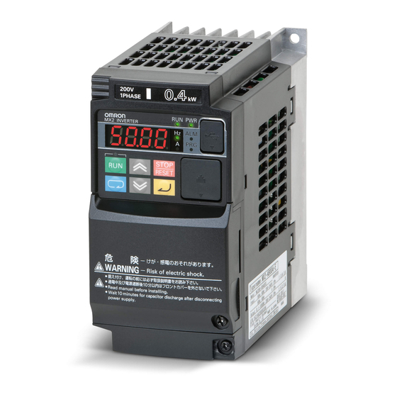
1 Overview Appearance and Part Names The following shows the front view when the product is unpacked (an example of 3G3MX2-A2001-V1/A2002-V1/A2004-V1/A2007-V1/AB2001-V1/AB2002-V1/AB2004-V1). Digital Operator Option Unit Cover Terminal Block Cover Open the terminal block cover to wire the main circuit terminal block and the control circuit terminal block. - Page 41 1 Overview The figures below show the components of each Inverter model. Single-phase 200 V, 0.1/0.2/0.4 kW 3-phase 200 V, 0.1/0.2/0.4/0.75 kW Single-phase 200 V, 0.75/1.5/2.2 kW 3-phase 200 V, 1.5/2.2 kW 3-phase 400 V, 0.4/0.75/1.5/2.2/3.0 kW (1) Cooling Fan Cover (5) Terminal Block Cover (2) Cooling Fan (6) Option Unit Cover...
- Page 42 1 Overview 3-phase 200 V, 3.7 kW 3-phase 400 V, 4.0 kW 3-phase 200 V, 5.5/7.5 kW 3-phase 400 V, 5.5/7.5 kW (1) Cooling Fan Cover (5) Terminal Block Cover (2) Cooling Fan (6) Option Unit Cover (3) Cooling Fin (7) Backing Plate (4) Inverter Case 1 - 10...
- Page 43 1 Overview 3-phase 200 V, 11 kW 3-phase 400 V, 11/15 kW 3-phase 200 V, 15 kW (1) Cooling Fan Cover (5) Terminal Block Cover (2) Cooling Fan (6) Option Unit Cover (3) Cooling Fin (7) Backing Plate (4) Inverter Case 1 - 11 Multi-function Compact Inverter 3G3MX2-V1 User’s Manual (I585-E1)
-
Page 44: Specifications
1 Overview Specifications 1-3-1 Standard Specifications 3-phase 200-V Class CT: Heavy load, VT: Light load Item 3-phase 200 V Model A2001 A2002 A2004 A2007 A2015 A2022 A2037 A2055 A2075 A2110 A2150 (3G3MX2- -V1) Maximum 0.75 applicable 0.75 18.5 motor 7 1/2 capacity 1 1/2 7 1/2... - Page 45 1 Overview 3-phase 400-V Class CT: Heavy load, VT: Light load Item 3-phase 400 V Model A4004 A4007 A4015 A4022 A4030 A4040 A4055 A4075 A4110 A4150 (3G3MX2- -V1) Maximum 0.75 applicable 0.75 18.5 motor 7 1/2 capacity 7 1/2 Rated out- 380 V 11.8 15.7...
- Page 46 1 Overview Single-phase 200-V Class CT: Heavy load, VT: Light load Item Single-phase 200 V Model AB001 AB002 AB004 AB007 AB015 AB022 (3G3MX2- -V1) Maximum 0.75 applicable 0.55 motor capacity 1 1/2 Rated out- 200 V put capac- ity [kVA] 240 V Single-phase 200 V −15% to 240 V +10%, 50/60 Hz ±5% Rated input voltage...
-
Page 47: Common Specifications
1 Overview Common Specifications Item Specifications Open type (IP20) Enclosure rating Control Control method Phase-to-phase sinusoidal modulation PWM 0.01 to 400 Hz Output frequency range Digital command: ±0.01% of the maximum frequency, Analog command: Frequency precision ±0.2% of the maximum frequency (25±10°C) Digital setting: 0.01 Hz, Analog setting: Maximum frequency ×... - Page 48 1 Overview Item Specifications Other AVR function, V/f characteristics switching, Upper/Lower limit, Multi-step speed (16 steps), Starting functions frequency adjustment, Jogging operation, Carrier frequency adjustment, PID control, Frequency jump, Analog gain/bias adjustment, S-shape acceleration/deceleration, Electronic thermal charac- teristics/level adjustment, Restart function, Torque boost function, Fault monitor, Soft lock function, Frequency conversion display, USP function, 2nd control function, UP/DOWN, Overcurrent sup- pression function, etc.
-
Page 49: External Dimensions
1 Overview 1-3-2 External Dimensions 68 (W) ϕ4.5 Power supply Model W [mm] H [mm] D [mm] D1 [mm] Single-phase 200 V 3G3MX2-AB001-V1 13.5 3G3MX2-AB002-V1 3G3MX2-AB004-V1 122.5 3-phase 200 V 3G3MX2-A2001-V1 13.5 3G3MX2-A2002-V1 3G3MX2-A2004-V1 122.5 3G3MX2-A2007-V1 145.5 1 - 17 Multi-function Compact Inverter 3G3MX2-V1 User’s Manual (I585-E1) - Page 50 1 Overview 108 (W) 2-ϕ4.5 Power supply Model W [mm] H [mm] D [mm] D1 [mm] Single-phase 200 V 3G3MX2-AB007-V1 3G3MX2-AB015-V1 170.5 3G3MX2-AB022-V1 3-phase 200 V 3G3MX2-A2015-V1 3G3MX2-A2022-V1 3-phase 400 V 3G3MX2-A4004-V1 143.5 3G3MX2-A4007-V1 3G3MX2-A4015-V1 170.5 3G3MX2-A4022-V1 3G3MX2-A4030-V1 *1. For the 3G3MX2-A4004-V1, this dimension is 4.3 mm. 1 - 18 Multi-function Compact Inverter 3G3MX2-V1 User’s Manual (I585-E1)
- Page 51 1 Overview 140 (W) 2-ϕ4.5 Power supply Model W [mm] H [mm] D [mm] D1 [mm] 3-phase 200 V 3G3MX2-A2037-V1 170.5 3-phase 400 V 3G3MX2-A4040-V1 1 - 19 Multi-function Compact Inverter 3G3MX2-V1 User’s Manual (I585-E1)
- Page 52 1 Overview 140 (W) 2-ϕ6 Power supply Model W [mm] H [mm] D [mm] D1 [mm] 3-phase 200 V 3G3MX2-A2055-V1 3G3MX2-A2075-V1 73.3 3-phase 400 V 3G3MX2-A4055-V1 3G3MX2-A4075-V1 1 - 20 Multi-function Compact Inverter 3G3MX2-V1 User’s Manual (I585-E1)
- Page 53 1 Overview 180 (W) 2-ϕ7 Power supply Model W [mm] H [mm] D [mm] D1 [mm] 3-phase 200 V 3G3MX2-A2110-V1 3-phase 400 V 3G3MX2-A4110-V1 3G3MX2-A4150-V1 1 - 21 Multi-function Compact Inverter 3G3MX2-V1 User’s Manual (I585-E1)
- Page 54 1 Overview 220 (W) 2-ϕ7 Power supply Model W [mm] H [mm] D [mm] D1 [mm] 3-phase 200 V 3G3MX2-A2150-V1 1 - 22 Multi-function Compact Inverter 3G3MX2-V1 User’s Manual (I585-E1)
-
Page 55: Restrictions
1 Overview Restrictions Restriction on PM Motor Mode Selecting the PM motor mode disables the following functions. • 2nd control • Torque control and torque limit functions • Encoder feedback function • Induction motor control function • Automatic Voltage Regulator (AVR) •... - Page 56 1 Overview Restriction on Modbus (RS-485) Communication When the inverter is used with any of the following communications units, the inverter’s RS-485 com- munications function cannot be used. Control the inverter from the host of each communications unit. • EtherCAT Communications Unit (Model: 3G3AX-MX2-ECT) •...
-
Page 57: Comparison With Previous Model
PM motors, which results in more efficient control than the conventional energy-saving control. This is combined with the OMRON’s unique auto-tuning function and initial pole position estimation function that estimates the magnetic pole position of a PM motor during startup to enable its smooth start. -
Page 58: Modbus Mapping Function
1 Overview DriveProgramming Function This inverter has the built-in DriveProgramming function as a simple sequence function. This enables a stand-alone inverter to perform simple sequence control. You can create programs easily in flowchart or text language method by using the CX-Drive. For details, refer to “DriveProgramming User’s Manual (I580)”. - Page 59 1 Overview Additions/Changes of Monitor Function The following monitor functions are added or improved to enhance the recognition of operations in your application. Parameter Parameter name Previous model d008 Real Frequency Monitor Improved to be displayed always when the Pulse Train Input RP Selection (P003) is set to 01 (Feedback pulse).
- Page 60 1 Overview Changes of Parameter Setting Range For the following parameters, the setting range is changed to expand the range of supported applications. Data range Parameter Parameter name Previous model 3G3MX2-V1 F002 1st Acceleration Time 1 F202 2nd Acceleration Time 1 F003 1st Deceleration Time 1 F203...
-
Page 61: Design
Design This section describes the installation environment and wiring methods. 2-1 Installation ........... 2-4 2-1-1 Inverter Installation . - Page 62 2 Design WARNING Turn off the power supply and implement wiring correctly. Not doing so may result in a serious injury due to an electric shock. Wiring work must be carried out only by qualified personnel. Not doing so may result in a serious injury due to an electric shock. Do not change wiring and slide switches, put on or take off Operator and optional devices, replace cooling fans while the input power is being supplied.
- Page 63 2 Design Precautions for Safe Use Installation and Storage Do not store or use the product in the following places. • Locations subject to direct sunlight. • Locations subject to ambient temperature exceeding the specifications. • Locations subject to relative humidity exceeding the specifications. •...
-
Page 64: Installation
2 Design Installation 2-1-1 Inverter Installation Mount the 3G3MX2-V1 Series Inverter vertically on a wall with the product’s longer sides upright. The material of the wall must be noninflammable such as a metal plate. For the mounting dimensions, refer to 1-3-2 External Dimensions on page 1-17. 2-1-2 Installation Environment Operating Environment Conditions... -
Page 65: Installation Conditions
2 Design Precautions for Correct Use Derating of the rated output current of the inverter may be required depending on the heavy/light load mode selection, operating ambient temperature, side-by-side installation, and carrier frequency setting. Use the inverter in an appropriate environment according to A-1 Derating on page A-2. Installation Conditions Keep the inverter clear of heating elements such as a braking resistor or reactor. - Page 66 2 Design Ambient Temperature Control To ensure reliable operation, use the inverter in an environment subject to minimal temperature rise as much as possible. If you install a ventilation fan in a control panel where several inverters are installed, be careful about the layout of the inverters and the air intake and ventilation apertures.
-
Page 67: Removal Of Each Part
2 Design Removal of Each Part 2-2-1 Removing Covers Before wiring each terminal block, you need to remove the terminal block cover and the backing plate. This section describes how to remove these covers. To install a communications option unit, you must remove the option unit cover beforehand. For how to install an option unit, refer to the user’s manual for each option unit. -
Page 68: Terminal Blocks
2 Design Installing Terminal Block Cover To install the terminal block cover, reverse the removal procedure. Install the terminal block cover on the inverter from the top and press it until you here a click. 2-2-2 Terminal Blocks Removing the terminal block cover and each connector cover reveals terminal blocks, connectors, and switches arranged as shown below. -
Page 69: Preparing Backing Plate
2 Design Name Description Charge Indicator Lights up even after power supply shutoff if the main circuit DC voltage (between the terminal P/+2 and terminal N/−) is approximately 45 V or higher. Make sure the charge indicator is not lit before wiring etc. Note For the description of the data display and operation keys, refer to Section 3 Operation and Test Run. -
Page 70: Wiring
2 Design Wiring 2-3-1 Standard Connection Diagram MCCB R/L1L (1) U/T1 S/L2 V/T2 T/L3 (N) W/T3 24 VDC For information on using external out- Short-circuit Motor put equipment or an external power Short-circuit bar supply, refer to Multi-function Input DC reactor Terminals and Programmable Con- troller Connection on page 2-36. -
Page 71: Arrangement And Function Of Main Circuit Terminal Block
2 Design 2-3-2 Arrangement and Function of Main Circuit Terminal Block The table below shows the arrangement of the main circuit terminal block and description of each terminal. Main Circuit Terminal Block The terminal arrangement shown on the left is P/+2 an example for the inverters with a capacity of 4.0 kW or lower. -
Page 72: Arrangement And Function Of Control Circuit Terminal Block
2 Design 2-3-3 Arrangement and Function of Control Circuit Terminal Block The table below shows the arrangement of the control circuit terminal block, and description and speci- fications of each terminal. Control Circuit Terminal Block Short-circuit bar (for sink logic) Terminal Terminal Item... - Page 73 2 Design Terminal Terminal Item Description Specifications symbol name Digital Power supply Input signal Common terminal for the internal common power supply, digital input, and analog I/O terminals. Input signal This is 24-VDC power supply for Allowable current: power sup- contact input signal.
- Page 74 2 Design Terminal Terminal Item Description Specifications symbol name Digital Output Open Multi-func- Select two functions from among Open collector output collector tion output 47 functions, and allocate them Between each termi- to terminals P1 and P2. These nal and PC terminals support both the sink Allowable voltage: logic and the source logic.
-
Page 75: Wiring For Main Circuit Terminals
2 Design Precautions for Correct Use The Multi-function Relay Output (MA, MB) Function Selection (C026) is, by default, set to 05 (AL: Alarm signal). However, this default data is based on different alarm output specifications from those of the previous models (3G3 V Series). The table below shows the relationship between the relay output status when the inverter input power supply is ON/OFF and the Multi-function Relay Output (MA, MB) Operation Selection (C036) setting. - Page 76 2 Design Main Circuit Configuration Diagram The diagram below shows the configuration of the inverter main circuit. The function of each peripheral component is also described. Name Function (a) (b) (c) Refer to Recommended Cable Size, Wiring Power supply Device, and Crimp Terminal on page 2-19. (d) AC reactor This is used as a harmonic suppression mea- sure.
- Page 77 2 Design Arrangement of Main Circuit Terminals The arrangement of terminals on the inverter main circuit terminal block is shown below. Applicable model Terminal arrangement 3G3MX2-A2001-V1 to A2007-V1 P/+2 N/− R/L1 S/L2 T/L3 U/T1 V/T2 W/T3 From power To motor supply Ground terminal (M4) x 2 3G3MX2-AB001-V1 to...
- Page 78 2 Design Applicable model Terminal arrangement 3G3MX2-A2037-V1 3G3MX2-A4040-V1 P/+2 N/− R/L1 S/L2 T/L3 U/T1 V/T2 W/T3 From power To motor supply Ground terminal (M4) x 2 3G3MX2-A2055-V1, A2075-V1 3G3MX2-A4055-V1, R/L1 S/L2 T/L3 U/T1 V/T2 W/T3 A4075-V1 P/+2 N/− From power To motor supply 3G3MX2-A2110-V1...
- Page 79 2 Design Recommended Cable Size, Wiring Device, and Crimp Terminal For inverter wiring, crimp terminal, and terminal screw tightening torque, refer to the table below. • Each table shows an example of connecting the standard 3-phase motor with four poles to an inverter.
- Page 80 2 Design 3-phase 400-V class Molded Maximum Rated Tightening Power cable, case Heavy/ applicable Terminal input torque ground cable circuit Model Light load motor screw current · *1*2 breaker mode capacity size [kW] (MCCB) Heavy load AWG16 (1.25) 3G3MX2-A4004-V1 Light load 0.75 AWG16 (1.25) Heavy load...
- Page 81 2 Design Wiring for Main Power Supply Input Terminals (R/L1, S/L2, T/L3) The following describes the wiring for the main power supply input terminals and for peripheral equip- ment. Installing molded case circuit breaker If the inverter’s protective function is activated, the inverter internal circuit may be damaged depend- ing on the condition.
- Page 82 For use with the phase S grounding, it is recommended to use the Input Noise Filter (Model: 3G3AX-NFI). • OMRON currently plans to support the EMC noise filters for the 3G3MX2-V1 Series. Installing magnetic contactor To shut off the main circuit power supply with a sequence, you can use a magnetic contactor (MC) on the inverter side closer than a molded case circuit breaker (MCCB).
- Page 83 2 Design Inrush current flow when the inverter power supply is turned ON When the inverter power supply is turned ON, the charging current, which is called inrush current, flows in the main circuit board capacitor. The table below shows the reference values at a power supply voltage of 200 V or 400 V when the power supply impedance is low.
- Page 84 2 Design Installing input noise filter The inverter performs high-speed output switching, which may cause the noise flow from the inverter to power supply lines that negatively affects on peripheral equipment. Therefore, it is recommended to use an input noise filter to reduce noise flowing out to power supply lines.
- Page 85 2 Design Harmonic Current Measures and DC/AC Reactor Wiring (+1, P/2) In recent years, there is an increasing concern about harmonic currents generated from industrial machinery. The following provides an overview of harmonics and measures against harmonics implemented in this inverter.
-
Page 86: Before Wiring
2 Design Causes of harmonics • General electrical equipment internally con- Voltage verts AC input power (commercial power) into DC power. At this time, harmonic currents occur because of the difference in the current Time flow direction between AC power and DC power. -
Page 87: Wiring Method
2 Design Wiring method With DC reactor DC reactor (optional) P/+2 Power MCCB supply R/L1 U/T1 S/L2 V/T2 T/L3 W/T3 3-phase 200 VAC Single-phase 200 VAC 3-phase 400 VAC *1. Connect to the terminals L1 and N on the single-phase 200-VAC inverter. With DC reactor and AC reactor DC reactor (optional) - Page 88 2 Design Wiring for Inverter Output Terminals (U/T1, V/T2, W/T3) The following describes the wiring for the inverter output terminals (U/T1, V/T2, W/T3). Never connect power supply to output terminals Never connect the power supply to the output terminals U/T1, V/T2, W/T3. The inverter is damaged internally if power supply voltage is applied to the output terminals.
- Page 89 2 Design Installing output noise filter Connecting a noise filter to the output side of the inverter enables the reduction of radio noise and inductive noise. 3G3AX-ZCL 3G3MX2-V1 Series 3G3AX-NFO Power MCCB supply Inverter Noise filter 3-phase 200 VAC 3-phase 400 VAC Inductive noise Radio noise Signal line...
- Page 90 2 Design Measures against radio noise Besides the I/O wires, radio noise is radiated from the inverter itself. This radio noise can be reduced by installing noise filters on both the input and output sides of the inverter and by installing and shielding the inverter body in a grounded iron enclosure etc. Keep the cables between the inverter and the motor as short as possible.
- Page 91 2 Design External Braking Resistor Connection Terminal (P/+2, RB)/ Regenerative Braking Unit Connection Terminal (P/+2, N/–) When driving a load with a large inertia or a vertical axis, regenerated energy is fed back to the inverter when it is decelerating or generating downward movement. If the amount of regenerative energy exceeds the amount allowable for the inverter, an overvoltage is detected.
- Page 92 2 Design • When using the Regenerative Braking Unit (Model: 3G3AX-RBU21/RBU22/RBU41) with a built-in braking resistor with the Braking Resistor (Model: 3G3AX-RBA/RBB/RBC), remove the built-in resistor according to the “Regenerative Braking Unit 3G3AX-RBU User’s Manual (I563)”. Using the Regenerative Braking Unit with the built-in resistor connected may cause damage to the built-in resistor.
-
Page 93: Wiring For Control Circuit Terminals
2 Design 2-3-5 Wiring for Control Circuit Terminals Wiring for Control Circuit Terminals • Although two terminals SC are internally connected, the terminal PC is a common terminal for input and analog signals and mutually isolated from them. Do not short-circuit or ground these common terminals. In addition, do not ground these common terminals via external equipment. - Page 94 2 Design Arrangement of Control Circuit Terminals The arrangement of terminals on the control circuit terminal block is shown below. Input common and Communications power supply Input RS-485 PSC P24 /GS2 /GS1 Short- Relay output circuit RS+ MP AM PC /EDM MB MA MC Communi-...
- Page 95 2 Design Wiring Method Push in the orange colored portion of the terminal with a flat-blade screwdriver (blade width: 2.5 mm max.) to open the wire insertion hole. With the flat-blade screwdriver pushed in, insert the wire or ferrule into the wire insertion (round) hole.
- Page 96 2 Design Multi-function Input Terminals and Programmable Controller Con- nection Sink logic When external power supply is used When inverter’s internal power supply for input (Remove the short-circuit bar from the control signal is used terminal block.) Short-circuit 24 VDC 24 VDC 24 VDC Output unit etc.
- Page 97 2 Design Multi-function Output Terminals and Programmable Controller Con- nection Sink logic Input 1 Input 2 Input common Input unit Inverter 24 VDC : Current flow Source logic Input 1 Input 2 24 VDC Input common Input unit Inverter : Current flow 2 - 37 Multi-function Compact Inverter 3G3MX2-V1 User’s Manual (I585-E1)
- Page 98 2 Design Precaution for Wiring Control Circuit Terminals Precaution for using more than one inverter If more than one inverter uses a common input (such as a switch), and their power-on timing is dif- ferent, a sneak current will flow in the circuit as shown below. This may cause the inverters to falsely recognize the input signal is ON even if it is OFF.
- Page 99 2 Design For source logic Power ON Power ON Short- circuit Input Input Add a diode Power OFF Power OFF Short- circuit Switch OFF Switch OFF In place of short-circuit bar, insert a diode With no diode inserted, the input turns ON to prevent sneak current.
-
Page 100: Wiring For Rs485 Communications Terminals
2 Design 2-3-6 Wiring for RS485 Communications Terminals This inverter has RS485 communications terminals on its control circuit terminal block. It uses the Modbus communication protocol to establish communications with external controllers. This section describes the wiring procedure for the RS485 communications terminal block and the installation of the terminating resistor. - Page 101 2 Design Terminating Resistor Setting Connect the inverters parallel to each other as shown below and, only on the terminal Inverter, turn ON the terminating resistor selector switch. Even if you have only one inverter connected, turn ON the terminating resistor selector switch. Selecting a terminating resistor appropriate to the cable impedance improves the terminating effect.
-
Page 102: Wiring For Digital Operator
2 Design 2-3-7 Wiring for Digital Operator In addition to the standard Digital Operator, this inverter can be operated via the optional Digital Opera- tor (Model: 3G3AX-OP01). To use the 3G3AX-OP01, you need the optional Digital Operator Cable (Model: 3G3AX-OPCN1 (1 m) or 3G3AX-OPCN3 (3 m)). -
Page 103: Safety Function (Under Application For Standards)
2 Design 2-3-8 Safety Function (Under Application for Standards) The safety function is designed so that the safety stop function of category 0 (uncontrolled stop) speci- fied in IEC 60204-1 is used to meet the safety standards of PLd under ISO 13849-1. Currently, this product is under application for safety standards. -
Page 104: Compliance With Ec Directives
Concepts of Compliance EMC Directive OMRON products are the electrical devices incorporated and used in various machines or manufac- turing equipment. For this reason, OMRON makes efforts to manufacture products that meet the related EMC standards so that the machines or equipment in which they are incorporated can easily comply with the EMC standards. - Page 105 2 Design EMC noise filters OMRON is currently preparing a line up of EMC noise filters. Wiring for power supply Keep the ground cable as short as possible. Place the inverter and the noise filter on the same earth (ground) plate.
- Page 106 2 Design • As a measure against harmonic distortion, an AC/DC reactor or harmonic suppression equipment is required. • Avoid placing noise-generating cables (such as power cables and motor cables of the inverter) in parallel with signal cables and allow a clearance of at least 25 cm between them. If you cannot avoid crossing two types of cables, keep them at right angles to each other.
- Page 107 2 Design Low-voltage directive The 3G3MX2-V1 Series Inverter complies with EN61800-5-1 when installed and wired to equipment according to the methods described below. • The 3G3MX2-V1 Series Inverter is an open type device. Be sure to install it inside the control panel. •...
- Page 108 2 Design 2 - 48 Multi-function Compact Inverter 3G3MX2-V1 User’s Manual (I585-E1)
- Page 109 Operation and Test Run This section describes the part names and key operation of the Digital Operator, and the operation method of this product as well as the test run procedure. 3-1 Operation of Digital Operator ........3-4 3-1-1 Part Names and Descriptions .
- Page 110 3 Operation and Test Run WARNING Do not change wiring and slide switches, put on or take off Operator and optional devices, replace cooling fans while the input power is being supplied. Doing so may result in a serious injury due to an electric shock.
- Page 111 3 Operation and Test Run Precautions for Correct Use Restart Selection Function Do not come close to the machine when using the Restart Selection function (b001, b008) because the machine may abruptly start when stopped by an alarm. Deceleration Stop Function Do not come close to the machine when selecting reset in Deceleration Stop Selection on Power Inter- ruption (b050) because the machine may abruptly start after the power is turned on.
-
Page 112: Operation Of Digital Operator
3 Operation and Test Run Operation of Digital Operator The Digital Operator is a display operation panel for the 3G3MX2-V1 Series Inverter. 3-1-1 Part Names and Descriptions The table below shows the name and function of each part of the Digital Operator. USB connector Data display RUN command... - Page 113 3 Operation and Test Run Display Name Description Mode key When parameter is displayed: Moves to the beginning of the next parameter group. When data is displayed: Cancels the setting and returns to the parameter display. In individual input mode: Moves the blinking position one digit to the left, if not located at the leftmost digit.
-
Page 114: Key Operation Method
3 Operation and Test Run 3-1-2 Key Operation Method This section explains how to use the Digital Operator keys in a typical operation (when the Display Selectionis “Complete display”) and in the extended function mode U as operation examples. This operation will be the same even if you select a setting other than Complete display in the Display Selection (b037), although the number of parameters that you will see on the display differs. -
Page 115: Transition Of Parameter Display
3 Operation and Test Run Transition of Parameter Display The following figure shows how to operate the Digital Operator to reach the intended parameter display. On the parameter display Moves to Data dis- Monitor Mode “d” play. Parameter display Data display d001: Output Frequency Monitor On the parame- Use the Increment/Decrement key to increase or... - Page 116 3 Operation and Test Run Transition of Parameter Display and Key Operation in Extended Function Mode U In the extended function mode U, you can operate the Digital Operator in the same way as in other modes. However, do not be confused although each parameter number is displayed again for the set value. Press the Enter key to enter the selected parameter number.
-
Page 117: Parameter Initialization
3 Operation and Test Run Parameter Initialization You can initialize the changed parameters and also clear the fault monitor data. As a measure to prevent inadvertent parameter initialization, the inverter is designed to force the user to set several parameters before execute initialization. For details on parameter initialization, refer to 5-1-2 Parameter Initialization on page 5-6. - Page 118 3 Operation and Test Run Individual Input Mode (Direct Input or Selection) If the parameter number or data is far away from the current value on the display, using the individual input mode is efficient for changing the parameter data. In the individual input mode, you can change the parameter number or data by selecting and entering a value digit by digit.
-
Page 119: Returning Display To D
3 Operation and Test Run Returning Display to d001 Regardless of the display mode of the Digital Operator, if you press (Mode key) for 3 seconds or more, the data of Output Frequency Monitor (d001) is displayed. However, the Digital Operator contin- ues to display the function mode and extended function mode in sequence as the normal operation if you press the Mode key for less than 3 seconds. - Page 120 3 Operation and Test Run This model: 3G3MX2 Series Name Previous model: 3G3JX Series etc. (both the previous 3G3MX2 and Type V1) Difference in key operation Cancels the setting and returns. Moves to the upper layer. Enters and stores the setting, and returns.
-
Page 121: Connections And Functions Of Cx-Drive
The Inverter/Servo support tool CX-Drive is support software to edit the inverter parameter settings. Installing the OMRON CX-One software on your PC also installs the CX-Drive simultaneously. The 3G3MX2-V1 Series Inverter is supported in the following or higher versions of the CX-Drive prod- uct: •... - Page 122 3 Operation and Test Run CX-Drive Connection Procedure There are two methods to connect the CX-Drive with the inverter. The step-by-step procedure for each method is provided below. Connecting by registering inverter connection method beforehand Create a new inverter project, set the connecting method, and connect with the inverter. Follow the steps below.
- Page 123 3 Operation and Test Run In the [New Drive] window, set the type of connection to the inverter. Under [Connection Type], select [Direct] and click the [Settings] button to the right. On the [Driver] tab, in [Port Selection], select the port name of the computer on which the CX-Drive is installed.
- Page 124 3 Operation and Test Run On the [Autodetect] tab, set the [Drive Type Selection], [Series Type Selection] and [Con- nection Type Selection]. Under [Drive Type Selection], select the [Inverter] box and click the [Inverter]. Then, under [Series Type Selection], select the [3G3MX2] box. Next, under [Connection Type Selection], select the [Direct] box and click the [Direct].
-
Page 125: Overview Of Cx-Drive Functions
3 Operation and Test Run After setting communications options, click the [OK] button and close all open windows. Then, click [Autodetect]. The Autodetect function starts to create new drive projects automatically. 3-2-2 Overview of CX-Drive Functions The Inverter/Servo support tool CX-Drive enables you edit the inverter parameters and monitor the inverter status. - Page 126 3 Operation and Test Run Precautions for Correct Use The CX-Drive, by default, does not allow connection to the inverter unless the software ver- sions match. • Software number of the inverter set in the CX-Drive project • Software number of inverter actually connected If you cannot connect to the inverter due to a software number mismatch, select [Tools] - [Options] in the menu bar and, in the [Online] tab, deselect the [Check Drive Software Compat- ibility] check box.
- Page 127 3 Operation and Test Run Status Function of CX-Drive Open the Status folder in the project and double-click the status information. The window corresponding to the selected status information opens. Display Description [Digital Inputs] Displays the current ON/OFF status information and function set to each input terminal.
- Page 128 3 Operation and Test Run Monitor Function of CX-Drive Open the Monitor folder in the project and double-click Real Time Trace. The Real Time Trance window opens, in which you can monitor the operation status of the inverter. • Up to 8 signals can be traced. •...
-
Page 129: Flow Of Test Run
3 Operation and Test Run Flow of Test Run Perform a test run of the inverter according to the following flow. Item Description Reference Installation Install the inverter according to the installation conditions. Section 2, Wiring and con- Connect the inverter to the power supply and peripheral equipment. Section 2, nections 2-10... -
Page 130: Operation Items For Test Run
3 Operation and Test Run Operation Items for Test Run The following describes the operation items for test run. Installation Check that the inverter meets the installation conditions. For details on installing the inverter, refer to 2-1 Installation on page 2-4. Wiring and Connections Select peripheral equipment according to the specifications and wire the cables securely. - Page 131 3 Operation and Test Run Display Status Checks If no problem is found at power-on, the display status will be as follows. Name Display status POWER LED ALARM LED Not lit RUN LED Not lit (Lit during RUN) RUN command LED indicator Data display LED (Hz) Data display Displays d001 setting.
-
Page 132: Parameter Setting
3 Operation and Test Run Precautions for Correct Use • The following parameters are not initialized: Total RUN Time Monitor (d016), Total Power ON Time Monitor (d017), Heavy Load/Light Load Selection (b049), Initialization Data Selection (b085), Initialization Target Setting (b094), FV/FI Adjustment (C081/C082), Thermistor Adjustment (C085), and Position Data at Power Off (P082). -
Page 133: No-Load Run
3 Operation and Test Run No-load Run Rotate the motor with no-load (in a state not connected to the mechanical system) via the Digital Oper- ator. Forward/reverse rotation via Digital Operator Follow the steps below to the motor in the forward or reverse rotation. (1) Set the Output Frequency Setting/Monitor (F001). -
Page 134: Load Run
3 Operation and Test Run Load Run If no problem is found during no-load run, connect the mechanical system and run the inverter with load via the Digital Operator. Mechanical system connection Make sure that the motor stopped completely before connecting the mechanical system. Then, connect the mechanical system with the motor securely to prevent the screws from loosening. -
Page 135: Parameter List
Parameter List This section provides the parameter lists that show monitor functions and available parameters for this inverter. 4-1 Monitor Mode ..........4-2 4-1-1 Group d . -
Page 136: Monitor Mode
4 Parameter List Monitor Mode The inverter by default displays the data of the parameter d001 after power-on. To monitor the desired parameter at power-on, change this default setting in the Initial Screen Selection (b038). The displayed parameters vary with the Display Selection (b037) setting. To display all parameters, set this parameter to 00 (Complete display). - Page 137 4 Parameter List Setting Changes Parameter Default Function name Monitor or data range during during Unit Page data −400. to −100. −99.9 to −10.0 Real Frequency − − − d008 P. 7-7 Monitor −9.99 to 99.99 100.0 to 400.0 Torque Reference −200.
- Page 138 4 Parameter List Setting Changes Parameter Default Function name Monitor or data range during during Unit Page data Digital Operator (F001) 01 to 15: Multi-step speed frequency 1 to 15 Jogging frequency Modbus communication Option Frequency Volume Reference Source − −...
-
Page 139: Function Mode
4 Parameter List Function Mode The table below lists the function mode parameters. The Monitor or data range column of the parameter list shows the range of parameters you can monitor or set on the Digital Operator (4-digit LED display) of the inverter. For the actual internal data range for this inverter, refer to 8-9 Modbus Communication Data Lists on page 8-37. -
Page 140: Extended Function Mode
4 Parameter List Extended Function Mode In the extended function mode, inverter parameters are categorized in six groups: A, b, C, H, P, and U. This section provides the parameter list for each group. Note that the parameters displayed on the Digital Operator vary with the setting in the Display Selection (b037). -
Page 141: Group A: Standard Function Parameters
4 Parameter List 4-3-1 Group A: Standard Function Parameters Setting Changes Parameter Default Function name Monitor or data range during during Unit Page data data 00: Digital Operator (Volume) 01: Control circuit terminal block 1st Frequency Refer- (Analog input) A001 Disabled Disabled ence Selection... - Page 142 4 Parameter List Setting Changes Parameter Default Function name Monitor or data range during during Unit Page data data 00: Binary (16-step selection with 4 terminals) Multi-step Speed − A019 Disabled Disabled Selection 01: Bit (8-step selection with 7 ter- minals) 0.00 1st Multi-step...
- Page 143 4 Parameter List Setting Changes Parameter Default Function name Monitor or data range during during Unit Page data data 00: Manual torque boost 1st Torque Boost − A041 Disabled Disabled Selection 01: Automatic torque boost 00: Manual torque boost 2nd Torque Boost −...
- Page 144 4 Parameter List Setting Changes Parameter Default Function name Monitor or data range during during Unit Page data data Startup DC Injec- 0. to 100./70. A057 Disabled Enabled tion Braking Power (Heavy load/Light load) Startup DC Injection A058 0.0 to 60.0 Disabled Enabled Braking Time...
- Page 145 4 Parameter List Setting Changes Parameter Default Function name Monitor or data range during during Unit Page data data 00: Disabled (Deviation = Target value − Feedback value) PID Deviation − A077 Disabled Enabled Reverse Output 01: Enabled (Deviation = Feedback value −...
- Page 146 4 Parameter List Setting Changes Parameter Default Function name Monitor or data range during during Unit Page data data A101 FI Start Frequency 0.00 to 99.99 0.00 Disabled Enabled A102 FI End Frequency 100.0 to 400.0 0.00 Disabled Enabled A103 FI Start Ratio 0.
- Page 147 4 Parameter List Setting Changes Parameter Default Function name Monitor or data range during during Unit Page data data 0.00 to Starting Frequency: Disabled Frequency above Starting Frequency Deceleration Stop A154 0.00 Disabled Enabled to 99.99 Frequency P. 7-37 100.0 to 400.0 0.0: Disabled Deceleration Stop A155...
-
Page 148: Group B: Detailed Function Parameters
4 Parameter List 4-3-2 Group b: Detailed Function Parameters Setting Changes Parameter Default Function name Monitor or data range during during Unit Page data data 00: Trip 01: 0-Hz restart Power Interruption/ 02: Frequency matching restart − b001 Undervoltage Disabled Enabled 03: Trip after frequency match- Restart Selection... - Page 149 4 Parameter List Setting Changes Parameter Default Function name Monitor or data range during during Unit Page data data Rated cur- 1st Electronic b012 rent of Disabled Enabled Thermal Level 0.20 × Rated current to 1.00 × inverter Rated current Rated cur- 2nd Electronic b212...
- Page 150 4 Parameter List Setting Changes Parameter Default Function name Monitor or data range during during Unit Page data data 00: Disabled 1st Overload Limit b021 Disabled Enabled 01: Enabled during acceleration Selection and constant speed 02: Enabled during constant − speed 2nd Overload Limit b221...
- Page 151 4 Parameter List Setting Changes Parameter Default Function name Monitor or data range during during Unit Page data data 00: Data other than b031 cannot be changed when terminal SFT is 01: Data other than b031 and the set frequency cannot be changed when terminal SFT is −...
- Page 152 4 Parameter List Setting Changes Parameter Default Function name Monitor or data range during during Unit Page data data 00: Four-quadrant separate setting 01: Terminal switching Torque Limit Selec- − b040 Disabled Enabled tion 02: Analog voltage input 03: Option (No applicable Option) Torque Limit 1 (Four-quadrant b041...
- Page 153 4 Parameter List Setting Changes Parameter Default Function name Monitor or data range during during Unit Page data data Set an upper limit level. Window Compara- Setting range: 0. to 100. b060 tor FV Upper Limit 100. Enabled Enabled Lower limit: Lower limit level + Hys- Level teresis width ×...
- Page 154 4 Parameter List Setting Changes Parameter Default Function name Monitor or data range during during Unit Page data data Ambient Tempera- −10 to 50 b075 Enabled Enabled °C P. 7-85 ture 00: Clear disabled Integrated Power − b078 Enabled Enabled Clear 01: Clear with the Enter key P.
- Page 155 4 Parameter List Setting Changes Parameter Default Function name Monitor or data range during during Unit Page data data 00: Disabled (Function not active) Regenerative 01: Enabled (Disabled during stop) − b095 Disabled Enabled Braking Selection 02: Enabled (Enabled during opera- tion and stop) 200-V class: 330.
- Page 156 4 Parameter List Setting Changes Parameter Default Function name Monitor or data range during during Unit Page data data 00: Disabled 01: Enabled (DC Injection Brak- Brake Control − b120 ing enabled during stop) Disabled Enabled Function Selection 02: Enabled (DC Injection Brak- ing disabled during stop) Brake Release Wait b121...
- Page 157 4 Parameter List Setting Changes Parameter Default Function name Monitor or data range during during Unit Page data data No trip (shut off by hardware) GS Input Operation − b145 Disabled Enabled P. 7-98 Selection Trip Inverter Display on 001 to 060 −...
-
Page 158: Group C: Multi-Function Terminal Function Parameters
4 Parameter List 4-3-3 Group C: Multi-function Terminal Function Parameters Setting Changes Parameter Function Default Monitor or data range during during Unit Page name data data 00: FW (Forward) 01: RV (Reverse) 02: CF1 (Multi-step speed setting binary 1) Multi-function 03: CF2 (Multi-step speed setting binary 2) C001 Input S1 Selec-... - Page 159 4 Parameter List Setting Changes Parameter Function Default Monitor or data range during during Unit Page name data data Multi-function C011 Input S1 Oper- Disabled Enabled ation Selection Multi-function C012 Input S2 Oper- Disabled Enabled ation Selection Multi-function C013 Input S3 Oper- Disabled Enabled ation Selection...
- Page 160 4 Parameter List Setting Changes Parameter Default Function name Monitor or data range during during Unit Page data data Output frequency Output current Output torque (Only in the sensorless vector control) Digital output frequency Output voltage Input power − C027 MP Selection Disabled Enabled...
- Page 161 4 Parameter List Setting Changes Parameter Default Function name Monitor or data range during during Unit Page data data 00: Enabled during acceleration/ deceleration and constant Low Current Signal − C038 Disabled Enabled speed Output Selection 01: Enabled during constant speed P.
- Page 162 4 Parameter List Setting Changes Parameter Default Function name Monitor or data range during during Unit Page data data 0.00: Not output arrival signal Arrival Frequency during acceleration. C042 During Acceleration 0.00 Disabled Enabled 0.01 to 99.99 100.0 to 400.0 P.
- Page 163 4 Parameter List Setting Changes Parameter Default Function name Monitor or data range during during Unit Page data data 03: 2400 bps 04: 4800 bps 05: 9600 bps Communication Speed 06: 19.2 kbps Selection − C071 Disabled Enabled P. 8-5 07: 38.4 kbps (Baud Rate Selection) 08: 57.6 kbps...
- Page 164 4 Parameter List Setting Changes Parameter Default Function name Monitor or data range during during Unit Page data data 00: Not store frequency data UP/DWN Storage − C101 Disabled Enabled P. 7-40 Selection 01: Store frequency data 00: Trip reset at power-on 01: Trip reset at power-off −...
- Page 165 4 Parameter List Setting Changes Parameter Default Function name Monitor or data range during during Unit Page data data Same as options for C021 (33 to 35: Logic Output Signal − C146 LOG1 to LOG3, 63: OPO, and 255: Disabled Enabled 2 Selection 2 no cannot be selected.)
-
Page 166: Group H: Motor Control Parameters
4 Parameter List 4-3-4 Group H: Motor Control Parameters Setting Changes Parameter Default Function name Monitor or data range during during Unit Page data data 00: Disabled 01: Enabled (No motor − H001 Auto-tuning Selection rotation) Disabled Disabled P. 6-4 02: Enabled (Motor rota- tion) 1st Motor Parameter... - Page 167 4 Parameter List Setting Changes Parameter Default Function name Monitor or data range during during Unit Page data data 1st Motor Parameter L Dependent H032 Disabled Disabled (Auto-tuning Data) on capacity 0.01 to 99.99 100.0 to 655.3 2nd Motor Parameter L Dependent H232 Disabled...
- Page 168 4 Parameter List Setting Changes Parameter Default Function name Monitor or data range during during Unit Page data data PM Motor Parameter R 0.001 to 9.999 Dependent Ω H111 Disabled Disabled (Auto-tuning Data) 10.00 to 65.53 on capacity PM Motor Parameter 0.01 to 99.99 Dependent H112...
-
Page 169: Group P: Option/Applied Function Parameters
4 Parameter List 4-3-5 Group P: Option/Applied Function Parameters Setting Changes Parameter Default Function name Monitor or data range during during Unit Page data data 00: Trip Operation Selection − P001 Disabled Enabled P. 7-101 on Option Error 01: Continue operation 00: Frequency setting (including PID) 01: Feedback pulse (enabled only Pulse Train Input... - Page 170 4 Parameter List Setting Changes Parameter Default Function name Monitor or data range during during Unit Page data data Communications Error P044 0.00 to 99.99 1.00 Disabled Disabled Detection Timer Setting 00: Trip 01: Trip after deceleration stop Operation Selection at P045 Host Communications 02: Ignore...
- Page 171 4 Parameter List Setting Changes Parameter Default Function name Monitor or data range during during Unit Page data data 0.0: Disconnection detection Encoder Disconnection disabled P077 Enabled Enabled P. 6-34 Detection Time 0.1 to 10.0 0. to 9999. Restarting Positioning P080 Disabled Disabled pulse P.
- Page 172 4 Parameter List Setting Changes Parameter Default Function name Monitor or data range during during Unit Page data data Number of Sent Data of − P140 All Stations in Co- 1 to 5 Enabled Enabled inverter Communication Recipient Station Num- ber of All Stations in Co- −...
- Page 173 4 Parameter List Setting Changes Parameter Default Function name Monitor or data range during during Unit Page data data P160 P161 P162 P163 Option I/F Flexible For- P164 − mat Output Register 1 0000 to FFFF hex 0000 Enabled Enabled P.
- Page 174 4 Parameter List Setting Changes Parameter Default Function name Monitor or data range during during Unit Page data data Standard Modbus address Modbus Mapping − P200 Disabled Disabled P. 8-25 Function Selection Modbus mapping enabled P201 P202 P203 P204 P205 Modbus Mapping Exter- −...
-
Page 175: Group U: User Parameters
4 Parameter List 4-3-6 Group U: User Parameters Setting Changes Parameter Default Function name Monitor or data range during during Unit Page data data U001 U002 U003 U004 U005 U006 U007 U008 U009 U010 U011 U012 U013 U014 U015 no: No registration U016 User Selection 1 to −... - Page 176 4 Parameter List 4 - 42 Multi-function Compact Inverter 3G3MX2-V1 User’s Manual (I585-E1)
-
Page 177: Basic Settings
Basic Settings This section describes the basic functions such as the Run command. 5-1 Parameter Display and Parameter Initialization ..... 5-3 5-1-1 Display Selection . - Page 178 5 Basic Settings 5-9-4 Forward RUN Command (FW) and Reverse RUN Command (RV) ..5-48 5-9-5 Multi-step Speed Operation Function ....... . 5-49 5-9-6 Jogging (JG) .
-
Page 179: Parameter Display And Parameter Initialization
5 Basic Settings Parameter Display and Parameter Initialization 5-1-1 Display Selection • You can select the parameters to be displayed on the Digital Operator. • To display all parameters, set this parameter to 00 (Complete display). Parameter No. Function name Data Default data Unit... - Page 180 5 Basic Settings Display condition Parameters displayed when condition is met To display parameters when 2nd Control Method C001 to C007 = 08 and A244 = is set to V/f control (con- A241 to A243, A246, A247 00 or 01 stant torque or reduced torque) To display parameters...
- Page 181 5 Basic Settings Basic Display (b037 = 04) • Displays only the basic parameters. • When this setting is selected, the following parameters are displayed. Parameter No. Function name Parameter No. Function name d001 to d155 Monitor function Power Interruption/Undervoltage b001 Restart Selection F001...
-
Page 182: Parameter Initialization
5 Basic Settings 5-1-2 Parameter Initialization • The parameter initialization function restores the changed parameters to the factory default settings. • It also can clear the fault monitor data. • As a measure to prevent inadvertent parameter initialization, you need to set several parameters to execute initialization. - Page 183 5 Basic Settings Precautions for Correct Use • Remember that it is impossible to undo the initialization once you press the Enter key ( to execute parameter initialization, with the Initialization Execution (b180) set to 01. • When the Soft Lock Selection (b031) is set to prohibit changes of the initialization-related parameters (b084, b094, b180), the initialization cannot be executed.
- Page 184 5 Basic Settings Clearing Fault Monitor Data Step 1: Press the Enter key Step 2: Press the Enter key Step 3: Clear is completed to set b084 to “04”. to set b180 to “01”. when the clearing display disappears. Clearing Clear completed Switching between 1st and 2nd Controls •...
-
Page 185: V/F Control Settings
5 Basic Settings V/f Control Settings 5-2-1 Control Method (V/f Characteristics) • V/f control is a method of controlling a motor by setting the output voltage and frequency of the inverter as V/f characteristics, which is effective for using the inverter easily. •... - Page 186 5 Basic Settings Reduced Torque Characteristics (VP 1.7th Power (VC at low speed)) This setting is suitable for fan, pump, and other applications that do not require large torque at low speeds. It provides high efficiency, reduced noise, and vibration, because the output voltage is reduced in the low speed range.
- Page 187 5 Basic Settings • The free V/f function is disabled by default. Even if you set 02 (Free V/f setting) in the 1st/2nd Control Method (A044/A244), the inverter cannot operate with the free V/f function. • If the free V/f function is enabled, the torque boost function (A041/A241, A042/A242, A043/A243), Base Frequency (A003/A203), and Maximum Frequency (A004/A204) settings are disabled.
-
Page 188: Heavy Load/Light Load Selection
5 Basic Settings Precautions for Correct Use Even if the Free V/f Frequency 1 to 7 are set to 800 V, the inverter cannot produce output voltage higher than the input voltage or the value of the 1st/2nd Motor Rated Voltage Selection (A082/A282). - Page 189 5 Basic Settings Changing the Heavy Load/Light Load Selection (b049) setting switches the setting ranges and default data of some parameters. Doing so also causes some parameter settings to be initialized at the same time. For these parameters, you must set data again after changing the b049 setting even if you configured them beforehand.
- Page 190 5 Basic Settings Initialization at Setting range Default data Para- mode switching Function meter name Heavy Light Heavy to Light to Heavy load (CT) Light load (VT) load (CT) load (VT) Light Heavy Carrier 2.0 to 15.0 [kHz] 2.0 to 10.0 [kHz] 10.0 [kHz] 2.0 [kHz] Enabled...
- Page 191 5 Basic Settings Parameter No. Function name Parameter No. Function name Overtorque/Undertorque Level C057 P036 Torque Bias Selection (Reverse Power Running) Overtorque/Undertorque Level C058 P037 Torque Bias Value (Forward Regeneration) Overtorque/Undertorque Signal C059 P038 Torque Bias Polarity Selection Operation Speed Limit Value in Torque Control H001 Auto-tuning Selection P039...
-
Page 192: Motor Parameter Settings
5 Basic Settings Motor Parameter Settings 5-3-1 Motor Capacity/Pole Number Selection Set the following parameters according to your motor. Parameter Function name Data Default data Unit 0.1/0.2/0.4/0.55/0.75/1.1/1.5/2.2/3.0/ Maximum applica- H003 1st Motor Capacity 3.7/4.0/5.5/7.5/11.0/15.0/18.5 ble motor capacity 0.1/0.2/0.4/0.55/0.75/1.1/1.5/2.2/3.0/ Maximum applica- H203 2nd Motor Capacity 3.7/4.0/5.5/7.5/11.0/15.0/18.5... -
Page 193: Additional Information
5 Basic Settings Parameter Function name Data Default data Unit b012 1st Electronic Thermal Level Rated 0.20 × Rated current to 1.00 × Rated current current of b212 2nd Electronic Thermal Level inverter 1st Electronic Thermal 00: Reduced torque characteristics (for b013 Characteristics Selection general-purpose motor) -
Page 194: Electronic Thermal Characteristics
5 Basic Settings Electronic Thermal Characteristics The electronic thermal function enables you to change the overload detection characteristics by setting the 1st/2nd Electronic Thermal Characteristics Selection (b013/b213) according to the motor in use. The reduced torque characteristics and the constant torque characteristics are achieved by setting the reduction factor for each output frequency of the inverter in the basic electronic thermal characteristics. -
Page 195: Constant Torque Characteristics
5 Basic Settings Constant torque characteristics Use the torque characteristics setting for dedicated inverter motors. Dedicated inverter motors are designed to prevent degradation of the cooling effect that arises as the motor speed increases, except at 5 Hz or less. For constant torque characteristics, the reduction factor is not defined for frequencies of 5 Hz or more. - Page 196 5 Basic Settings Electronic thermal detection of the inverter In the 3G3MX2-V1 Series Inverter, the electric thermal function is separated for the inverter and for the motor. The electronic thermal function for the inverter is fixed to the rated current value of the inverter, inde- pendent of the b012/b212 setting.
-
Page 197: Base Frequency And Maximum Frequency Of Motor
5 Basic Settings 5-3-3 Base Frequency and Maximum Frequency of Motor To configure the V/f control characteristics output to the motor, set the base frequency and maximum frequency of your motor. For the base frequency, set the rated frequency of the motor (the frequency listed on the motor rating nameplate). -
Page 198: Run Command Settings
5 Basic Settings RUN Command Settings 5-4-1 RUN Command Selection Select the input method for the RUN command. Parameter Function name Data Default data Unit Control circuit terminal block (DriveProgramming) 1st/2nd RUN Com- − Digital Operator A002/A202 mand Selection Modbus communication Option Forward RUN Direction... - Page 199 5 Basic Settings • An example of inverter operation with forward command (FW) input and reverse command (RV) input is shown below. Output frequency Output Frequency Setting Forward Time Reverse RUN indicator Forward command FW input Reverse command RV input 5 - 23 Multi-function Compact Inverter 3G3MX2-V1 User’s Manual (I585-E1)
-
Page 200: Frequency Reference Settings
5 Basic Settings Frequency Reference Settings 5-5-1 Frequency Reference Selection • Select the input method for the frequency reference in 1st/2nd Frequency Reference Selection (A001/A201). • When the multi-step speed reference function is used (by setting the multi-function input terminals for the Multi-step Speed Reference 0 to 15), the setting in A001/A201 is enabled only for the Multi-step Speed Reference 0. - Page 201 5 Basic Settings Below are the details of the data of A001/A201. Data Frequency reference source Sets the frequency reference via the volume control on the external Digital Operator (Model: 3G3AX-OP01). Sets the frequency reference via the control circuit terminal block (analog input signals). (FV-SC, FI-SC) Sets the frequency reference via the Digital Operator.
- Page 202 5 Basic Settings The frequency reference methods that are used generally are shown below. Using Digital Operator (Volume) Set the frequency reference via the volume control for frequency setting on the Digital Operator (Model: 3G3AX-OP01). Data display RUN command LED indicator Operation keys Volume control for frequency setting...
- Page 203 5 Basic Settings Parameter No. Function name Data Default data Unit 1st/2nd Frequency − A001/A201 Digital Operator (F001) Reference Selection Using an Analog Voltage Input or Analog Current Input To use an analog voltage input or analog current input to set the frequency reference, set the parame- ters as shown in the table below.
- Page 204 5 Basic Settings Using an Analog Voltage Input or Analog Current Input by Switching To switch between the analog voltage and analog current inputs to set the frequency reference, set the parameters as shown in the table below. This enables switching between the frequency reference input (voltage reference) and frequency refer- ence input (current reference) terminals.
- Page 205 5 Basic Settings Using Multi-step Speed Reference Allocate one of the Multi-function Input S1 to S7 Selection (C001 to C007) to 02 to 05 or 32 to 38 (Multi-step speed) and turn ON that terminal. This enables the inverter to perform multi-step speed operation, independent of Frequency Reference Selection (A001/A201) settings.
-
Page 206: Frequency Reference Correlation Chart
5 Basic Settings 5-5-2 Frequency Reference Correlation Chart To set the frequency reference, you need to set the 1st/2nd Frequency Reference Selection (A001/A201). Alternatively, you can switch the frequency reference via multi-function input or from a communications option unit. Below is a correlation chart among the priority, related parameters, and related multi-func- tion input terminals when the frequency reference is switched. -
Page 207: Frequency Limit
5 Basic Settings Precautions for Correct Use The Output Frequency Setting/Monitor (F001) shows the frequency reference in the internal memory (RAM). F001 displays the frequency reference value selected at that time. If you change the frequency reference value displayed in F001 and save it (by pressing the Enter key), the data will be stored with the multi-step speed reference selected at that time. - Page 208 5 Basic Settings Using an Analog Voltage Input or Analog Current Input (FV-SC, FI-SC) Setting the lower limit causes the inverter to output the frequency set in the 1st/2nd Frequency Lower Limit (A062/A262) when 0V (4 mA) is input to the frequency reference. The graph below shows the FV/FI characteristics with the default analog input start/end function settings (FV: A011 to A015, FI: A101 to A105).
-
Page 209: Acceleration/Deceleration Time Settings
5 Basic Settings Acceleration/Deceleration Time Settings 5-6-1 Acceleration/Deceleration Time Settings • Set the motor acceleration/deceleration time. To accelerate/decelerate slowly, set a large value. To accelerate/decelerate quickly, set a small value. • The set time here indicates the acceleration/deceleration time from 0 Hz to the maximum frequency. The actual acceleration/deceleration time varies depending on the frequency reference value. -
Page 210: Acceleration/Deceleration Pattern
5 Basic Settings Parameter Default Function name Data Unit data F002 1st Acceleration Time 1 Acceleration time from 0 to maxi- mum frequency 0.00 to 99.99 10.00 F202 2nd Acceleration Time 1 100.0 to 999.9 1000. to 3600. F003 1st Deceleration Time 1 Deceleration time from maximum frequency to 0 0.00 to 99.99... - Page 211 5 Basic Settings Parameter Default Function name Data Unit data Line A097 Acceleration Pattern Selection S-shape curve − U-shape curve A098 Deceleration Pattern Selection Inverted U-shape curve EL-S-shape curve A131 Acceleration Curve Parameter 01 (Small curve) to 10 (Large − curve) A132 Deceleration Curve Parameter...
- Page 212 5 Basic Settings Pattern Curve Parameter (Curve Factor) Set the Acceleration Curve Parameter/Deceleration Curve Parameter (A131/A132) according to the fol- lowing table. S shape (A097/A098=01) U shape (A097/A098=02) Inverted U shape (A097/A098=03) Output frequency [Hz] Output frequency [Hz] Output frequency [Hz] Target Target Target...
-
Page 213: 2-Step Acceleration/Deceleration Function
5 Basic Settings 5-6-3 2-step Acceleration/Deceleration Function • Use the 2-step acceleration/deceleration function to switch between two acceleration/deceleration time settings or change the acceleration/deceleration time on the way during acceleration/decelera- tion. • The acceleration/deceleration time switching method can be selected from the following three. •... - Page 214 5 Basic Settings (Example 1) When 1st/2nd 2-step Accelera- (Example 2) When 1st/2nd 2-step Accelera- tion/Deceleration Selection (A094/A294) is set to tion/Deceleration Selection (A094/A294) is set to 00 Switch via 2CH terminal 01 Switch by setting Acceleration 2 Deceleration 2 A095/A295 A096/A296 Accelera-...
-
Page 215: Stop Method Settings
5 Basic Settings Stop Method Settings 5-7-1 Stop Selection • Select whether you want the motor to make a deceleration stop according to the deceleration time setting or a free-run stop, when the STOP command is input via the Digital Operator or the control cir- cuit terminal block. - Page 216 5 Basic Settings 02: Frequency pull-in restart Causes the inverter to restart by outputting the starting frequency set in the Starting Frequency Selection at Frequency Pull-in Restart (b030) to the motor in a free-run stop state and re-acceler- ating when the Frequency Pull-in Restart Level (b028) is reached. This enables a smooth restart independently of the voltage between motor terminals.
- Page 217 5 Basic Settings (Example 1) 0-Hz restart (b088 = 00) (Example 2) Frequency matching start (b088 = 01) Free-run Free-run 0-Hz start Motor Motor rotation rotation speed speed b003 Frequency matching start • The inverter restarts at 0 Hz independent of the •...
-
Page 218: Stop Key Selection
5 Basic Settings 5-7-3 STOP Key Selection • Enable/disable the STOP/RESET key on the Digital Operator. • This setting is enabled when the 1st/2nd RUN Command Selection (A002/A202) is not set to 02 (Dig- ital Operator). However, when the 1st/2nd RUN Command Selection (A002/A202) is set to 02 (Digital Operator), the STOP/RESET key is enabled independent of this setting. -
Page 219: Reset Method Settings
5 Basic Settings Reset Method Settings 5-8-1 Reset • Use the reset function to reset the trip status of the inverter. This function is used also when the inverter is running normally to shut off the inverter output. To prevent the reset function from being activated when the Inverter is running normally, set the Reset Selection (C102) to 02 (Enabled only during trip) or 03 (Reset only during trip). - Page 220 5 Basic Settings Precautions for Safe Use Be sure to confirm the RUN signal is not input before resetting the alarm because the machine may abruptly start. Precautions for Correct Use • The reset function clears the data of calculated electronic thermal function and calculated usage rate of regenerative braking.
-
Page 221: Restart After Resetting
5 Basic Settings 5-8-2 Restart after Resetting • In the Reset Restart Selection (C103), select the restart method after trip reset is executed. However, when the Reset Selection (C102) is set to 03 (Trip reset only), the inverter restarts from 0 Hz independently of the C103 setting. - Page 222 5 Basic Settings (Example 1) Frequency matching restart When the Restart Standby Time (b003) elapses, the inverter detects the motor frequency and executes the frequency matching restart function without stopping the motor rotation. If an overcurrent trip occurs during a frequency matching restart, increase the restart standby time.
-
Page 223: Multi-Function Input Settings
5 Basic Settings Multi-function Input Settings 5-9-1 Multi-function Input Selection • You can allocate the functions shown in the following table to the multi-function input terminals S1 to S7 to use them. • This section describes seven types of primary functions. For other functions, refer to 7-2 Multi-function Input/Output Functions on page 7-18. -
Page 224: Multi-Function Input Operation Selection
5 Basic Settings 5-9-2 Multi-function Input Operation Selection The multi-function input terminals can be set to either NO (NO contact) or NC (NC contact) individually. This manual describes each function with the Multi-function Input S1 to S7 Operation Selection (C011 to C017) set to 00 (NO: NO contact). -
Page 225: Multi-Step Speed Operation Function
5 Basic Settings 5-9-5 Multi-step Speed Operation Function • Use this function to switch the frequency reference set in the Multi-step Speed Reference 0 to 15 based on the combination of inputs to multi-function input terminals. • For multi-step speed operation, you can select either 4-terminal binary operation (in 16 steps maxi- mum) or 7-terminal bit operation (in 8 steps maximum). - Page 226 5 Basic Settings Binary Operation • Setting the Multi-function Input S1 to S7 Selection (C001 to C007) to 02 (CF1) to 05 (CF4) enables the selection of the multi-step speed 0 to 15. • Use the Multi-step Speed Reference 1 to 15 (A021 to A035) to set the frequency for the multi-step speed 1 to 15.
- Page 227 5 Basic Settings Bit Operation • Setting the Multi-function Input S1 to S7 Selection (C001 to C007) to 32 (SF1) to 38 (SF7) enables the selection of the multi-step speed 0 to 7. • Use the Multi-step Speed Reference 1 to 7 (A021 to A027) to set the frequency for SF1 to SF7. •...
-
Page 228: Jogging (Jg)
5 Basic Settings 5-9-6 Jogging (JG) • When the jogging function is enabled, jogging operation starts when the RUN command is input. • To enable the jogging function, set the Multi-function Input S1 to S7 Selection (C001 to C007) to 06 (JG: Jogging). -
Page 229: 2-Step Acceleration/Deceleration (2Ch)
5 Basic Settings Enabled during operation When the Jogging Stop Selection (A039) is set to 03, 04, or 05, jogging operation is performed even if the FW signal turns ON first. However, if the JG signal turns OFF first, the motor falls in a free-run stop state. During Normal Jogging operation... -
Page 230: 3-Wire Input Function (Sta, Stp, F/R)
5 Basic Settings 5-9-9 3-wire Input Function (STA, STP, F/R) • Use this function to start and stop the inverter via an automatic reset contact such as a pushbutton switch. • Allocate the Multi-function Input S1 to S7 Selection (C001 to C007) to 20 (STA), 21 (STP), and 22 (F/R). -
Page 231: Multi-Function Output Settings
5 Basic Settings 5-10 Multi-function Output Settings 5-10-1 Multi-function Output Selection • You can allocate the functions shown in the following table to the multi-function output P1 and P2 terminals, and the multi-function relay output (MA, MB) terminals. • This section describes seven types of primary functions. For other functions, refer to 7-2 Multi-function Input/Output Functions on page 7-18. -
Page 232: Multi-Function Output On/Off Delay Time
5 Basic Settings 5-10-3 Multi-function Output ON/OFF Delay Time • Each multi-function output terminal can be allocated with the ON/OFF delay time independently. • Because all output signals turn ON/OFF immediately when the set conditions are met, depending on the selected signal, chattering may occur. In such a case, use this function to hold or delay the signal. •... -
Page 233: Constant Speed Arrival Signal (Fa1)
5 Basic Settings 5-10-5 Constant Speed Arrival Signal (FA1) • This signal is output when the output frequency reaches the frequency set in the Output Frequency Setting/Monitor. In F001, the frequency reference selected at that time is displayed. • Allocate one of the Multi-function Output P1/P2 Selection (C021/C022), or Multi-function Relay Out- put (MA, MB) Function Selection (C026), to 01 (FA1). -
Page 234: 0-Hz Detection Signal (Zs)
5 Basic Settings Precautions for Correct Use The Multi-function Relay Output (MA, MB) Function Selection (C026) is, by default, set to 05 (AL: Alarm output). However, this default data is based on different alarm output specifications from those of the previous models (3G3 V Series). The table below shows the relationship between the relay output status when the inverter input power supply is ON/OFF and the Multi-function Relay Output (MA, MB) Operation Selection (C036) setting. -
Page 235: Operation Ready (Irdy)
5 Basic Settings 5-10-8 Operation Ready (IRDY) • This signal is output when the inverter becomes ready to operate (ready to accept the RUN command). • When this command is not output, the inverter does not operate even if the RUN command is input. •... -
Page 236: Torque Boost Function Settings
5 Basic Settings 5-11 Torque Boost Function Settings 5-11-1 Torque Boost • Use the torque boost function to raise the output torque if it is not sufficient at low speeds. • This inverter provides two torque boost options: Manual torque boost for manual torque adjustment and Automatic torque boost for automatic torque adjustment. -
Page 237: Automatic Torque Boost
5 Basic Settings Automatic Torque Boost • In the 3G3MX2-V1 Series Inverter, the default data for A041/A241 were changed to Automatic torque boost (A041/A241 = 01). With this setting, the inverter increases the output voltage automatically depending on the load condi- tion. -
Page 238: Manual Torque Boost
5 Basic Settings Manual Torque Boost • In the manual torque boost function, set the output voltage and output frequency characteristics of the inverter. • The automatic torque boost function automatically adds the output voltage and output frequency to the characteristics set in the manual torque boost function. •... -
Page 239: Measures Against Overvoltage
5 Basic Settings 5-12 Measures against Overvoltage 5-12-1 Overvoltage Suppression Function during Deceleration • Use this function to prevent overvoltage trip caused by the regenerative energy from the motor during deceleration. • Enable or disable the function in the Overvoltage Suppression Function Selection During Decelera- tion (b130). - Page 240 5 Basic Settings (Example 1) (Example 2) When DC voltage is kept constant (b130 = 01) When acceleration is enabled (b130 = 02) Main circuit DC voltage [V] Main circuit DC voltage [V] Overvoltage Overvoltage suppression control level level (b131) (b131) Time [s] Time [s]...
-
Page 241: Regenerative Braking Function
5 Basic Settings 5-12-2 Regenerative Braking Function • When the motor decelerates, moves downward, or is rotated by an external load (that is, when the output torque direction and the rotation direction are opposite), it serves as a generator and the regenerated energy is fed back to the inverter. - Page 242 5 Basic Settings Parameter Default Function name Data Unit data 0.0: Regenerative braking not active 0.1 to 100.0 (Limited by b097) The usage rate must be set as a percentage (%) as follows: Allowable braking frequency [%] of the connected braking resistor or lower.
-
Page 243: Vector Control And Applied Functions
Vector Control and Applied Functions This section describes the vector control and applied functions characteristic of this inverter. 6-1 Sensorless Vector Control ........6-3 6-1-1 Sensorless Vector Control Parameter Settings . - Page 244 6 Vector Control and Applied Functions 6-8 PM Motor Mode ..........6-53 6-8-1 PM Motor and PM Motor Control .
-
Page 245: Sensorless Vector Control
6 Vector Control and Applied Functions Sensorless Vector Control The rotation speed of an induction motor, by its characteristic, decreases as the output torque increases. Selecting sensorless vector control improves this relationship between the output torque and the rota- tion speed of an induction motor, which results in a high output torque even at low speeds. With sensorless vector control enabled, this inverter can output a high starting torque, 200% of the motor rating, at 0.5Hz. -
Page 246: Offline Auto-Tuning For Motor Parameters
6 Vector Control and Applied Functions 6-1-2 Offline Auto-tuning for Motor Parameters • Use this function to measure and automatically set the motor parameters required for sensorless vector control. • To use the sensorless vector control method, perform auto-tuning to measure the motor parameter values. - Page 247 6 Vector Control and Applied Functions Offline Auto-Tuning Steps Offline auto-tuning consists of the following five steps: • Presetting of parameters • Selection of motor rotation during auto-tuning • Auto-tuning • Operations after auto-tuning • Operations in case of error Presetting of parameters (1) Set the 1st/2nd Motor Capacity (H003/H203) and the 1st/2nd Motor Pole Number (H004/H204) according to your motor.
- Page 248 6 Vector Control and Applied Functions Selection of motor rotation during auto-tuning In the Auto-tuning Selection (H001), select whether or not to rotate the motor during auto-tuning. Parameter No. Function name Data Default data Unit Disabled − H001 Auto-tuning Selection Enabled (No motor rotation) Enabled (Motor rotation) Set value...
- Page 249 6 Vector Control and Applied Functions Precautions for Correct Use • Even if you set H001 to 01 (Auto-tuning without motor rotation), for example, the 4-pole motor may rotate by approximately up to 1/8 of a rotation (half the inverse of poles). •...
- Page 250 6 Vector Control and Applied Functions Parameter No. Function name Data Default data Unit 00: Standard motor parameter 1st/2nd Motor Parameter 02: Auto-tuning parameter (Applies − H002/H202 Selection H030/H230 to H034/H234 data to motor parameters.) 1st/2nd Motor Parameter H030/H230 R1 (Auto-tuning Data) 0.001 to 9.999 Ω...
-
Page 251: Motor Parameter Settings
6 Vector Control and Applied Functions 6-1-3 Motor Parameter Settings • Normally, you perform offline auto-tuning to set motor parameters. However, if the offline auto-tuning process is aborted, for example, when the inverter does not reach 50% of its rated current during auto-tuning, you need to set the motor parameters manually. •... -
Page 252: Adjustments For Sensorless Vector Control
6 Vector Control and Applied Functions 6-1-4 Adjustments for Sensorless Vector Control • To use sensorless vector control method, perform offline auto-tuning. If you cannot perform offline auto-tuning, set motor parameters appropriately according to 6-1-3 Motor Parameter Settings on page 6-9. •... -
Page 253: Reverse Rotation Prevention Function
6 Vector Control and Applied Functions Reverse Rotation Prevention Function This function is enabled only when the 1st/2nd Control Method (A044/A244) is set to 03 (Sensorless vector control). When sensorless vector control is enabled, the inverter may output a rotation signal opposite to the RUN command direction at low speeds, depending on the current accuracy. -
Page 254: Torque Limit Function
Use this mode to set the torque limit value from optional equipment. At present, OMRON provides no options that support this mode. • Setting one of the Multi-function Input S1 to S7 Selection (C001 to C007) to 40 (TL: Torque limit enabled) enables the torque limit function set in the Torque Limit Selection (b040) only when the ter- minal TL is input. - Page 255 6 Vector Control and Applied Functions Default Parameter No. Function name Data Unit data 0. to 200. Torque Limit 2 255: no (Torque limit disabled) b042 200. (Four-quadrant Mode Reverse Regeneration torque limit Reverse Regeneration) when b040 = 00 0. to 200. Torque Limit 3 255: no (Torque limit disabled) b043...
-
Page 256: Torque Ladstop Function Settings
6 Vector Control and Applied Functions Precautions for Correct Use When the torque limit function is used in a low speed range, the inverter may fail to start the motor and detect an overload. In this case, use this function in conjunction with the overload limit selection (b021/b221/b024). -
Page 257: Overtorque/Undertorque Function
6 Vector Control and Applied Functions Overtorque/Undertorque Function 6-3-1 Overtorque/Undertorque Function Settings Use this function to detect that the estimated motor output torque value exceeded the set level and out- put the overtorque signal. • This function is enabled only when the 1st/2nd Control Method (A044/A244) is set to 03 (Sensorless vector control). -
Page 258: Torque Control
6 Vector Control and Applied Functions Torque Control The 3G3MX2-V1 Series Inverter provides the torque control mode. This section describes the torque control settings and functions. 6-4-1 Torque Control Settings The inverter provides torque control that controls the output torque of the motor. •... -
Page 259: Torque Bias Function Settings
6 Vector Control and Applied Functions Torque Bias Value Torque limit (P037) Terminal ATR Torque reference Torque reference (Reference value for input torque control) Speed control (P control) Speed Speed limit The Speed control (P control) operates when a monitor value speed detection value exceeds the speed limit value. -
Page 260: V/F Control With Speed Feedback
6 Vector Control and Applied Functions V/f Control with Speed Feedback The 3G3MX2-V1 Series Inverter can perform V/f control with speed feedback with the pulse train input function included as standard. This control enables highly accurate and stable speed control based on the feedback of the pulse gen- erator (PG) signal or the phase-A/B signal from the encoder. -
Page 261: Recommended Encoder And Its Wiring
6 Vector Control and Applied Functions Details of Pulse Train Input Type Selection (P004) The Pulse Train Input Type Selection (P004) setting causes the inverter to recognize the feedback rotation direction as shown below. Multi-function RUN command Pulse Train Input Type Recognized feedback rotation Input S7 Selection (P004) setting... - Page 262 6 Vector Control and Applied Functions Recommended product E6C3-CWZ5GH (Manufacturer: OMRON) Additional Information Crosstalk : A phenomenon by which signals are erroneously transmitted between different phases. Specifically, the rising/falling edge signal from phase A is superimposed on the signal from phase B and the rising/falling edge signal from phase B is superim- posed on the signal from phase A, respectively.
- Page 263 6 Vector Control and Applied Functions Complementary Output 3G3MX2 Series Inverter (Model: E6C3-CWZ5GH) 24-V power 24-V power supply (Brown) supply 7.5 Ω Phase A (Black) 3.9 kΩ 510 Ω 6.2 kΩ 24 Ω Phase B 5.1 V (White) 7.5 Ω 4.7 kΩ...
- Page 264 6 Vector Control and Applied Functions 3G3MX2 Encoder Direction Complementary-output type encoder Sink transistor 3G3MX2 Encoder Direction Complementary-output type encoder Source transistor 6 - 22 Multi-function Compact Inverter 3G3MX2-V1 User’s Manual (I585-E1)
-
Page 265: Protective Detection Under V/F Control With Speed Feedback
6 Vector Control and Applied Functions 6-5-3 Protective Detection under V/f Control with Speed Feedback The V/f control with speed feedback performs the following protective detection based on the speed feedback data. Use these functions according to your application. Overspeed error detection If the speed feedback value exceeds the value set in the Overspeed Error Detection Level (P026), the inverter detects the E81. -
Page 266: Adjustments For V/F Control With Speed Feedback
6 Vector Control and Applied Functions 6-5-4 Adjustments for V/f Control with Speed Feedback You can adjust the V/f control with speed feedback function with the gain settings shown below. However, the function cannot be adjusted when using a motor that causes an extremely large slip (10% of the rated rotation speed or higher) or in applications where such a large load that causes the motor to stall (or step out) is applied. -
Page 267: Brake Control Function
6 Vector Control and Applied Functions Brake Control Function The 3G3MX2-V1 Series Inverter has a built-in brake control function for an elevating system etc. Use this function to control the external brake used in an elevating system etc. from the inverter. The brake control function can be used independently of the 1st/2nd Control Method (A044/A244) Selection. -
Page 268: Brake Control Function Settings
6 Vector Control and Applied Functions (4) After the brake confirmation signal turns ON (after releasing the brake), the inverter waits until the Acceleration Wait Time on Brake Control (b122) elapses and acceler- ates again to the set frequency. During deceleration (5) After the RUN command turns OFF, the inverter decelerates to the Brake Force Fre- quency (b127) and turns OFF the brake release signal (C021, C022, C026 = 19: BRK). - Page 269 6 Vector Control and Applied Functions Parameter Default Function name Data Unit data 00: Disabled 01: Enabled (DC Injection Braking Brake Control Function − b120 enabled during stop) Selection 02: Enabled (DC Injection Braking dis- abled during stop) 0.00 to 5.00 The time from when the inverter reaches the Brake Release Frequency until it out- b121...
-
Page 270: Simple Position Control
6 Vector Control and Applied Functions Simple Position Control The 3G3MX2-V1 Series Inverter can perform simple position control with the pulse train input function included as standard. This control mode enables positioning to a maximum of eight target positions based on the feedback of the Phase A and B 90°phase difference pulse train from the encoder etc. -
Page 271: Recommended Encoder For Simple Position Control And Its Wiring
6 Vector Control and Applied Functions Details of Pulse Train Input Type Selection (P004) The Pulse Train Input Type Selection (P004) setting causes the inverter to recognize the feedback rotation direction as shown below. RUN command Multi-function Pulse Train Input Type Recognition of feedback rotation Input S7 Selection (P004) setting... - Page 272 Therefore, this provides a stable output from the encoder. Recommended product E6C3-CWZ5GH (Manufacturer: OMRON) Additional Information Crosstalk : A phenomenon by which signals are erroneously transmitted between different phases. Specifically, the rising/falling edge signal from phase A is superimposed on the signal from phase B and the rising/falling edge signal from phase B is superim- posed on the signal from phase A, respectively.
- Page 273 6 Vector Control and Applied Functions Complementary Output 3G3MX2 Series Inverter (Model: E6C3-CWZ5GH) 24-V power 24-V power supply (Brown) supply 7.5 Ω Phase A (Black) 3.9 kΩ 510 Ω 6.2 kΩ 24 Ω Phase B 5.1 V (White) 7.5 Ω 4.7 kΩ...
- Page 274 6 Vector Control and Applied Functions Wiring for Single-phase Pulse Signal and Direction Signal (P004 = 01 or 03) Connect the single-phase pulse signal or single-phase pulse + direction signal as shown in the diagram below. • Connect the single-phase pulse signal to the pulse train input RP terminal. •...
- Page 275 6 Vector Control and Applied Functions Encoder Wiring Check When you finish wiring the encoder, follow the steps below to check the encoder wiring. (1) Turn ON the power supplies for both the inverter and the encoder. (2) Set the parameter data according to 6-7-1 Feedback Settings for Simple Position Control on page 6-28.
-
Page 276: Simple Position Control Operation And Settings
6 Vector Control and Applied Functions If problem occurs during wiring check If any problem occurs during the wiring check, refer to the following table to take corrective action. Problem Cause Check/Remedy The motor/encoder rotates in The motor/encoder wiring for for- Reverse the wiring for the phase-A and opposite directions during for- ward or reverse rotation is con-... - Page 277 6 Vector Control and Applied Functions (4) The inverter starts decelerating when the motor reaches the position short of the tar- get position by the sum of the amount of decelerating movement for the accelera- tion/deceleration set time and the Creep Speed Moving Amount (P014). (5) When the frequency set in the Creep Speed Setting (P015) is reached during deceler- ation, the motor moves at the creep speed.
- Page 278 6 Vector Control and Applied Functions Frequency/ Speed Actual motor speed Output Time frequency Output frequency/ Actual speed Forward Rotation direction judged based on single-phase Reverse pulse (P004 = 00) Position error Forward Actual rotation direction Reverse Precautions for Correct Use •...
- Page 279 6 Vector Control and Applied Functions Simple Position Control Settings The simple position control is a function only available for the 1st control. It does not work if you switch to the 2nd control. In addition, when the simple position control is set, the torque control is disabled. The terminal ATR (Torque reference input permission) is disabled.
- Page 280 6 Vector Control and Applied Functions Parameter Function name Data Default data Unit Position range setting (reverse side) (P073) to position range setting (for- Multi-step Position Com- P060 ward side) (P072) pulse mand 0 (Displays upper 4 digits including “−”) (×1 multiplication) 0 to 268435455 Position Limit Setting...
- Page 281 6 Vector Control and Applied Functions Encoder disconnection detection When the inverter outputs the frequency set in the Creep Speed Setting (P015) or higher, if the speed feedback value does not reach the Starting Frequency (b082) within the Encoder Disconnec- tion Detection Time (P077), the inverter detects the E80.
-
Page 282: Origin Search Function, Current Position Preset, Position Data Storage At Power Shutoff
6 Vector Control and Applied Functions 6-7-4 Origin Search Function, Current Position Preset, Position Data Storage at Power Shutoff When the power supply is turned on, the inverter clears the current position data to zero before startup. Therefore, you need to establish the origin for position control before performing simple position con- trol. - Page 283 6 Vector Control and Applied Functions Operation of Origin Search Function The origin search function starts when the origin search start signal turns ON, and establishes the origin at the point when the origin search limit signal turns ON. The origin search function has two origin search modes as shown below.
- Page 284 6 Vector Control and Applied Functions Origin search mode 2 This mode provides a method to improve the processing time and accuracy of origin search by switching between two frequency settings in the origin search mode. In the Origin Search Mode 2 Frequency (P071), set a high frequency to move to the proximity of the origin in a short time.
- Page 285 6 Vector Control and Applied Functions Origin Search Function Settings Configure the origin search function settings as shown below based on the required operation. • In the Origin Search Mode (P068), set the origin search mode to use. • In the Origin Search Direction Selection (P069), set the direction in which to start the origin search function according to your application.
-
Page 286: Position Data Storage At Power Shutoff
6 Vector Control and Applied Functions Parameter Default Function name Data Unit data Position Control Mode − P075 Limit Selection Pulse Train Input RP Feedback pulse (Enabled only when − P003 Selection 1st control is selected) Position Limit Setting (Reverse Side) (P073) P083 Preset Position Data to Position Limit Setting (Forward Side) -
Page 287: Restarting Positioning
6 Vector Control and Applied Functions 6-7-5 Restarting Positioning If the motor moves out of the restarting positioning range after position control is executed by the simple position control function, the inverter automatically starts repositioning it again. To enable the restarting positioning function, set parameters as follows: •... -
Page 288: Position Command Selection 1 To
6 Vector Control and Applied Functions Parameter Default Function name Data Unit data Multi-step Position P060 Command 0 Multi-step Position P061 Command 1 Multi-step Position P062 Command 2 Multi-step Position Position Limit Setting (Reverse Side) (P073) to P063 Command 3 Position Limit Setting (Forward Side) (P072) pulse (Displays upper 4 digits including “−”) -
Page 289: Turntable Control
6 Vector Control and Applied Functions 6-7-7 Turntable Control This function is useful when using a system of rotating coordinates such as those of a turn table. It performs positioning based on the amount of movement per rotation of the rotating coordinates in the direction in which the moving distance is shorter. -
Page 290: Speed/Position Switching
6 Vector Control and Applied Functions 6-7-8 Speed/Position Switching Use this function to switch between simple position control and speed control (frequency operation). Set the Multi-function Input S1 to S7 Selection (C001 to C007) to 73 (SPD: Speed/Position switching). • Turn ON the SPD (Speed/Position switching) terminal to switch from simple position control to speed control (frequency operation). -
Page 291: Interlock Function With Simple Position Control And Brake Control
6 Vector Control and Applied Functions 6-7-9 Interlock Function with Simple Position Control and Brake Control The 3G3MX2-V1 Series Inverter has the interlock function with simple position control and brake control. This function is useful in applications where brake control is required, such as an elevator or equipment that must be kept in the stop position. - Page 292 6 Vector Control and Applied Functions (3) After outputting the brake release signal, the inverter waits for the brake confirma- tion signal (C001 to C007 = 44: BOK) to turn ON during the time set in the Brake Error Detection Time (b124). If the brake confirmation signal does not turn ON within the time set in b124, the inverter outputs the brake error signal (C021, C022, C026 = 20: BER) and detects the E36.
- Page 293 6 Vector Control and Applied Functions Settings of Interlock Function with Simple Position Control and Brake Control This section describes the settings related to the interlock function with simple position control and brake control. For the simple position control settings, refer to 6-7-3 Simple Position Control Operation and Settings on page 6-34.
- Page 294 6 Vector Control and Applied Functions Parameter Default Function name Data Unit data 0.00 to 5.00 Set the mechanical delay time from when the Acceleration Wait Time b122 brake confirmation signal (or brake release 0.00 on Brake Control signal) turns ON until the brake is activated actually.
-
Page 295: Pm Motor Mode
6 Vector Control and Applied Functions PM Motor Mode The 3G3MX2-V1 Series Inverter provides the PM motor mode. This mode enables the Inverter to control a synchronous motor (PM motor) which is more efficient than an induction motor (IM motor). This section describes the PM motor mode. - Page 296 6 Vector Control and Applied Functions Precautions for Correct Use • Check the maximum allowable current (limiting current beyond which demagnetization occurs) for your PM motor. The inverter could output approximately 300% of the rated output current of the inverter. Select a PM motor as follows to prevent demagnetization.
-
Page 297: Functional Limitations In Pm Motor Mode
6 Vector Control and Applied Functions 6-8-2 Functional Limitations in PM Motor Mode In the PM motor mode, induction motor-related functions and some other functions cannot be used. Parameters for these unavailable functions are not displayed in the PM mode. In addition, for some parameters, the default data are changed for use with the PM motor. - Page 298 6 Vector Control and Applied Functions Unavailable Selection Functions The following parameter selection functions are not available and therefore not displayed on the Digital Operator. Parameter No. Function name Unavailable selection functions Power Interruption/Undervoltage Frequency pull-in restart b001 Restart Selection Overvoltage/Overcurrent Restart Frequency pull-in restart b008...
-
Page 299: Switching To Pm Motor Mode
6 Vector Control and Applied Functions 6-8-3 Switching to PM Motor Mode To use PM motor control, you need to switch the inverter to the PM motor mode. Follow the steps below to switch to the PM motor mode: (1) Set the Inverter Mode Selection (b171) to 03 (PM motor). (2) Set the Initialization Execution (b180) to 01 (Execute initialization), then press the Enter key. - Page 300 6 Vector Control and Applied Functions (2) Set the rated frequency of the motor in the 1st Base Frequency (A003) and set the maximum frequency in the 1st Maximum Frequency (A004). The rated/maximum frequency values can be calculated from the rated/maximum rotation speed of the PM motor as follows: ] ×...
- Page 301 6 Vector Control and Applied Functions Parameter Function name Data Default data Unit PM motor Parame- 0001 to 9999 (0.0001 to 0.9999) Dependent H109 ter Ke 1.000 to 6.553 on capacity (rad/s) 0.001 to 9.999 10.00 to 99.99 PM motor Parame- Dependent H110 ter J...
- Page 302 6 Vector Control and Applied Functions Precautions for Correct Use • Even if you set H001 to 01 (Auto-tuning without motor rotation), for example, the 4-pole motor may rotate by approximately up to1/8 of a rotation (half the inverse of poles). •...
-
Page 303: Pm Motor Parameter Settings
6 Vector Control and Applied Functions Precautions for Correct Use • If a trip occurs during auto-tuning, the auto-tuning process will be forcibly ended. In this case, the inverter displays a trip display in preference to the abort display. Refer to 10-1-2 Alarm Code List on page 10-4. - Page 304 6 Vector Control and Applied Functions PM Motor Parameter Ld (H107) Set the d-axis inductance (in mH) of the motor in Y-connection. Alternatively, set 50% of the phase-to-phase inductance of the motor measured with an LCR meter. Be sure to set this parameter so that Ld is equal to or less than Lq. Not doing so may result in an overload.
-
Page 305: Adjustment Of Pm Motor Mode Settings
6 Vector Control and Applied Functions Parameter Default Function name Data Unit data 0001 to 9999 (0.0001 to 0.9999) Dependent H109 PM Motor Parameter Ke on capacity (rad/s) 1.000 to 6.553 0.001 to 9.999 10.00 to 99.99 Dependent H110 PM Motor Parameter J on capacity 100.0 to 999.9 1000. - Page 306 6 Vector Control and Applied Functions Parameter Default Function name Data Unit data PM Motor Initial Pole Position Esti- H131 0 to 255 time mation 0V Waiting Times PM Motor Initial Pole Position Esti- H132 0 to 255 time mation Detection Waiting Times PM Motor Initial Pole Position Esti- H133 0 to 255...
- Page 307 6 Vector Control and Applied Functions Adjust- Operation status Phenomenon Adjustment method ment item If the motor rotation is unstable during startup, increase the motor starting time. Rotation is unsta- H117 However, setting this parameter to an excessively large ble. value may cause an overload.
- Page 308 6 Vector Control and Applied Functions PM Motor Initial Pole Position Estimation The PM motor initial pole position estimation function estimates the magnetic pole position of the PM motor in a stop state and causes the inverter to start its output according to the estimated magnetic pole position.
- Page 309 6 Vector Control and Applied Functions Precautions for Correct Use • Although high-tone sound occurs during startup when the PM Motor Starting Method Selec- tion (H123) is set to 01 (Initial pole position estimation enabled), it is not a fault. •...
- Page 310 6 Vector Control and Applied Functions 6 - 68 Multi-function Compact Inverter 3G3MX2-V1 User’s Manual (I585-E1)
-
Page 311: Other Functions
Other Functions This section describes the details of functions not described in Section 5 or Section 6. 7-1 Monitor Mode ..........7-4 7-1-1 Output Frequency Monitor [d001] . - Page 312 7 Other Functions 7-1-33 Analog Voltage Input FV Monitor [d130] ......7-16 7-1-34 Analog Current Input FI Monitor [d131] .
- Page 313 7 Other Functions 7-7-3 Power Recovery Restart Prevention Function (USP) ....7-67 7-7-4 Deceleration Stop on Power Interruption Function ..... 7-68 7-8 Functions Related to Protection, Warning, and Various Output Signals 7-72 7-8-1 Free-electronic Thermal Function .
-
Page 314: Monitor Mode
7 Other Functions Monitor Mode This section describes the output frequency, fault monitor during trip, and other monitor functions of the inverter. 7-1-1 Output Frequency Monitor [d001] Use this function to display the output frequency of the inverter. The value is 0.00 when the inverter is stopped. -
Page 315: Run Direction Monitor [D003]
7 Other Functions 7-1-3 RUN Direction Monitor [d003] Use this function to display the RUN direction of the inverter. The RUN LED is lit during inverter operation (forward/reverse RUN). Parameter Default Function name Data Unit data F : Forward − −... -
Page 316: Multi-Function Output Monitor [D006]
7 Other Functions 7-1-6 Multi-function Output Monitor [d006] Use this function to display the output status of each multi-function output terminal, based on whether the corresponding 7-segment LED is lit or not lit. Each LED shows the output status detected by the built-in CPU. Note that this is independent of the NO/NC contact setting for each multi-function output terminal. -
Page 317: Real Frequency Monitor [D008]
7 Other Functions Additional Information • When the 1st/2nd Frequency Reference Selection (A001/A201) is set to 02 (Digital Operator: F001), if the d001/d007 Data Setting Selection (b163) is set to 01 (Enabled), you can change the Output Frequency Monitor (After Conversion) (d007) by the Increment/Decrement key only during operation. -
Page 318: Torque Bias Monitor [D010]
7 Other Functions 7-1-10 Torque Bias Monitor [d010] Use this function to display the current torque bias value under sensorless vector control. The torque bias monitor function estimates the torque value equivalent to the rated current of the inverter as 100%. To convert it to the rated motor torque ratio, use the following formula: Rated motor torque ratio = Monitor value ×... -
Page 319: Input Power Monitor [D014]
7 Other Functions 7-1-13 Input Power Monitor [d014] Use this function to display the input power (instantaneous value) of the inverter. Parameter Default Function name Data Unit data − d014 Input Power Monitor 0.0 to 100.0 7-1-14 Integrated Power Monitor [d015] Use this function to display the integrated power of the inverter. -
Page 320: Total Run Time Monitor [D016]
7 Other Functions 7-1-15 Total RUN Time Monitor [d016] Use this function to display the total RUN time of the inverter. This parameter value will be stored to the inverter’s EEPROM when the power supply is shut off. Parameter Default Function name Data Unit... -
Page 321: Life Assessment Monitor [D022]
7 Other Functions 7-1-18 Life Assessment Monitor [d022] Use this function to display the life assessment status based on whether the corresponding 7-segment LED is lit or not lit. This function is intended for the following two items. For details on the life assessment, refer to 7-8-14 Cooling Fan Life Warning Signal (WAF) on page 7-85 or 7-8-12 Capacitor Life Warning Signal (WAC) on page 7-84. -
Page 322: Position Command Monitor [D029]
7 Other Functions 7-1-21 Position Command Monitor [d029] Use this function to display the position command value in the simple position control mode. When the Simple Position Control Selection (P012) is set to 02 (Simple position control enabled), it displays the position command monitor value that is currently set. For details on simple position control, refer to 6-7 Simple Position Control on page 6-28. -
Page 323: Dual User Monitor [D050]
7 Other Functions 7-1-23 Dual User Monitor [d050] Use this function to display two set monitor items by switching between them with the Increment/Decre- ment key. In b160 and b161, set the parameter numbers whose data you want to monitor. (Example) To monitor the d001 data, set b160 or b161 to 001. -
Page 324: Frequency Reference Source Monitor [D062]
7 Other Functions 7-1-25 Frequency Reference Source Monitor [d062] Set the frequency reference in the 1st/2nd Frequency Reference Selection (A001/A201). Alternatively, you can switch the frequency reference via a multi-function input terminal or from a com- munications option unit. The Frequency Reference Source Monitor displays the frequency reference source enabled for the inverter. -
Page 325: Fault Monitor 1 To 6 [D081 To 086]
7 Other Functions 7-1-28 Fault Monitor 1 to 6 [d081 to 086] Use these functions to display the fault history of the last six faults. This count value will be stored to the inverter’s EEPROM when the power supply is turned OFF. The latest fault history is displayed in the Fault Monitor 1 (d081). -
Page 326: Regenerative Braking Load Rate Monitor [D103]
7 Other Functions 7-1-31 Regenerative Braking Load Rate Monitor [d103] Use this function to display the regenerative braking load rate. If this monitor value exceeds the value set in the Usage Rate of Regenerative Braking (b090), the inverter will trip with the alarm code E06 (Braking resistor overload protection). -
Page 327: Pulse Train Input Rp Monitor [D133]
7 Other Functions 7-1-35 Pulse Train Input RP Monitor [d133] Use this function to display the pulse train command or feedback value that is input to the pulse train input terminal RP in units of percentage as 100% of the 1st/2nd Maximum Frequency (A004/A204). This function is enabled independently of the Pulse Train Input RP Selection (P003) setting. -
Page 328: Multi-Function Input/Output Functions
7 Other Functions Multi-function Input/Output Functions This section describes the I/O signal settings for this inverter. 7-2-1 Multi-function Input Selection You can use the function set by allocating the Multi-function Input S1 to S7 Selection (C001 to C007) to the functions listed below. The multi-function input terminals S1 to S7 can be set to either NO contact or NC contact individually in the Multi-function Input S1 to S7 Selection (C011 to C017). -
Page 329: Other Functions
7 Other Functions Parameter Reference Data Description Reference item page PID: PID disabled PID Function P. 7-44 PIDC: PID integral reset Remote operation accelerated DWN: Remote operation decelerated Remote Operation Function P. 7-40 UDC: Remote operation data clear OPE: Forced operator function Forced Operator Function P. -
Page 330: Multi-Function Output Selection
7 Other Functions 7-2-2 Multi-function Output Selection Use this function to allocate the functions listed below by setting the Multi-function Output P1/P2 Selec- tion (C021/C022), or Multi-function Relay Output (MA, MB) Function Selection (C026). The multi-func- tion output P1 and P2 terminals are for open-collector output and the multi-function relay output (MA, MB) terminals are for relay output. - Page 331 7 Other Functions Reference Data Description Reference item page MO1: General-purpose output 1 − MO2: General-purpose output 2 DriveProgramming Function MO3: General-purpose output 3 IRDY: Operation ready Operation Ready P. 5-59 FWR: Forward run signal Forward run signal P. 5-59 RVR: Reverse run signal Reverse run signal...
-
Page 332: Analog I/O Settings
7 Other Functions Analog I/O Settings This section describes the analog I/O signal settings for this inverter. 7-3-1 Analog Input (FV, FI) This inverter has two types of external analog input terminals. Frequency reference (Analog voltage input) between terminals FV and SC : 0 to 10 V This terminal also treats input via the variable resistor (volume) as voltage input to the inverter. - Page 333 7 Other Functions *1. This switches the frequency reference among the volume, current, and voltage based on the FV/FI Selection (A005) setting and the status of the multi-function input terminal allocated to 16 (AT: Analog input switching). Here, volume represents the volume control (VR) on the optional Digital Operator (Model: 3G3AX-OP01). *2.
-
Page 334: Analog Input Filter
7 Other Functions 7-3-2 Analog Input Filter This function is effective for removing noise in the analog input circuit. Use it to set an input filter for voltage or current input when using an external analog signal to input the frequency reference. -
Page 335: Analog Input Adjustment
7 Other Functions 7-3-4 Analog Input Adjustment You can change the analog input gain. Use this function to fine-tune the analog input signal. For how to set the scale conversion, for example, from 0-to-10 V to 0-to-5 V, refer to 7-3-5 Analog Input Start/End Function Settings on page 7-25. - Page 336 7 Other Functions Parameter Default Function name Data Unit data 0.00 to 400.0 A011/A101/ FV/FI/VR Start Frequency Set the frequency at which to start ana- 0.00 A161 log input. 0.00 to 400.0 A012/A102/ FV/FI/VR End Frequency Set the frequency at which to end ana- 0.00 A162 log input.
-
Page 337: Terminal Mp (Pulse/Pwm Output)
7 Other Functions (Example 2) A015/A165 = 01 (0 Hz) Maximum frequency A012/A102/A162 Output frequency is 0 Hz for 0% to A013/A103/A163. (A015/A105/A165 = 01 (0 Hz)) A011/A101/A161 Analog input A013/ A014/ 100% A103/ A104/ (FV/FI) A163 A164 (0 V) (10 V) (0 mA) (20 mA) - Page 338 7 Other Functions *1. 07 (LAD frequency) represents the frequency commanded by the inverter and is equivalent of the Output Fre- quency Monitor (d001) value. 00 (Output frequency) represents a frequency value that takes into account the aspects of vector control compensation (such as sensorless vector control) and even stabilization control. When set to 00 (Output frequency), the parameter may produce an output that appears to be unstable at low speeds, for example, when decelerating due to the overload limit function.
-
Page 339: Terminal Am (Analog Output)
7 Other Functions 7-3-7 Terminal AM (Analog Output) The terminal AM provides an analog output of 0 to 10 VDC. The digital terminal AM on the control circuit terminal block enables the monitoring of the output fre- quency and the output current. AM Selection Select the signal you want to output from the following table. - Page 340 7 Other Functions AM Gain/Bias Setting Adjust the gain and bias settings of the inverter’s AM output based on the meter connected to the termi- nal AM. The bias setting is once disabled while the reset input is input, and 0 V is output. Parameter Default Function name...
-
Page 341: Inverter Control Settings
7 Other Functions Inverter Control Settings This section describes the carrier frequency function and the 1st/2nd control switching function, which are related to the inverter control. 7-4-1 Carrier Frequency Use this function to change the carrier frequency output from the inverter in a PWM waveform. Set a higher carrier frequency value to reduce the metallic noise generated by the motor. -
Page 342: Automatic Carrier Reduction
7 Other Functions 7-4-2 Automatic Carrier Reduction Use this function to reduce the carrier frequency automatically as the output current and the cooling fin temperature increase. To enable this function, set the Automatic Carrier Reduction (b089) to 01 or 02. Parameter Default Function name... -
Page 343: 2Nd Control Function (Set)
7 Other Functions 7-4-3 2nd Control Function (SET) Use this function to control two induction motors with different motor parameters by switching. Even with a single motor, you can use the 2nd control to configure the control and settings that best fit your application. - Page 344 7 Other Functions 1st control motor 2nd control motor Setting item H022 H222 Motor Parameter L H023 H223 Motor Parameter Io H024 H224 Motor Parameter J H030 H230 Motor Parameter R1 (Auto-tuning Data) H031 H231 Motor Parameter R2 (Auto-tuning Data) H032 H232 Motor Parameter L (Auto-tuning Data)
-
Page 345: Other Operation Functions
7 Other Functions Other Operation Functions This section describes the parameters associated with other operation functions. 7-5-1 Starting Frequency Set the frequency at which the inverter starts its output when the RUN signal turns ON. Mainly, use this function to adjust the starting torque. If you set a high frequency in Starting Frequency (b082), the inverter starts with the full voltage and also the starting current increases. -
Page 346: Reduced Voltage Startup Selection
7 Other Functions 7-5-2 Reduced Voltage Startup Selection Use this function to increase the voltage slowly during motor startup. To prevent the surge current or overcurrent trip during startup, increase the value set in the Reduced Voltage Startup Selection (b036). Although setting a small value causes the high starting torque, the inverter operates as with the full voltage starting. -
Page 347: Acceleration/Deceleration Stop Function
7 Other Functions 7-5-4 Acceleration/Deceleration Stop Function This function causes the inverter stop accelerating/decelerating temporarily and start running at a con- stant speed at the frequency output at that time. If the moment of inertia of a load machine is large, you can use it, for example, to have the motor wait until the amount of motor slip during acceleration/deceleration becomes small. -
Page 348: Run Direction Limit Selection
7 Other Functions 7-5-5 RUN Direction Limit Selection Use this function to limit the RUN direction of the motor. It can be activated either via the control circuit terminal block or the Digital Operator. When the inverter receives a RUN command input with the RUN direction limit function enabled from the control circuit terminal block, is displayed on the Digital Operator. -
Page 349: Frequency Calculation Function
7 Other Functions 7-5-7 Frequency Calculation Function The frequency calculation function enables the use of calculation results from two frequency reference channels as a frequency reference or PID feedback value. To use the calculation result as a frequency reference, set the 1st/2nd Frequency Reference Selection (A001/A201) to 10 (Operation function output). -
Page 350: Remote Operation Function (Up/Dwn)
7 Other Functions 7-5-9 Remote Operation Function (UP/DWN) Use this function to change the inverter output frequency via the multi-function input terminals UP and DWN. Set the Multi-function Input S1 to S7 Selection (C001 to C007) to 28 (UP) and 28 (DWN). When the UP/DOWN terminal is ON, the inverter operates according to the acceleration/deceleration time settings (F002/F202, F003/F203, etc.) In addition, setting C101 to 01 (Store frequency data) enables the inverter to store the frequency refer-... -
Page 351: Output Voltage Gain
7 Other Functions 7-5-10 Output Voltage Gain Use this function to decrease the inverter output voltage as a percentage of the voltage set in the 1st/2nd Motor Rated Voltage Selection (A082/A282). You can avoid motor hunting by decreasing the output voltage gain. Be sure to change the gain value moderately during operation (as a guide, 10% max.) Otherwise, an overcurrent trip may occur due to sudden output voltage changes. -
Page 352: Avr (Automatic Voltage Regulator) Function
7 Other Functions 7-5-11 AVR (Automatic Voltage Regulator) Function Use this function to have the inverter automatically compensate for the output voltage to the motor even if the incoming voltage fluctuates. It is useful as a preventive measure against low output torque to the motor or overexcitation. Note, however, that the inverter cannot output voltage exceeding the incoming voltage to the inverter. - Page 353 7 Other Functions Adjusting overexcitation control during deceleration (1) First, set A083 to 0.3 and A084 to 130 to shorten the deceleration time. (2) If you need to set a higher target value for the deceleration time, or to detect an over- voltage with the above settings, first set A083 to 0 and increase the value set in A084 gradually from 130 while checking the deceleration time at each gain level.
-
Page 354: Pid Function
7 Other Functions 7-5-12 PID Function Use this function to control the flow rate, air volume, pressure, and other processes. To use this func- tion, set A071 to 01 (Enabled) or 02 (Enabled: Reverse output enabled). The PID function can be disabled during PID operation via external signal input. To use this function, set one of the Multi-function Input S1 to S7 Selection (C001 to C007) to 23 (PID: PID disabled). - Page 355 7 Other Functions Parameter Default Function name Data Unit data 0.0 to 25.5 PID Sleep Operation A157 Set the delay time until the sleep operation Delay Time starts. 0.0 to 100.0 PID Deviation Excessive C044 Level OD signal output judgment level 0.0 to 100.0 Feedback Comparison C052...
- Page 356 7 Other Functions PID Operation (1) P Operation In this operation, the control volume is proportional to the deviation (difference between the target value and the current value). Step transition Ramp transition Target value Large Large A072 A072 Control volume Small Small (2) I Operation...
-
Page 357: Feedback Selection
7 Other Functions Feedback Selection Select the terminals used to input the feedback signal in PID Feedback Selection (A076). When the 1st Frequency Reference Selection (A001) is set to 01 (Control circuit terminal block), the analog input setting other than that selected in A076 is used as the target frequency reference. In this case, the setting in A005 and the function allocated to the terminal AT (Analog input switching) are dis- abled. - Page 358 7 Other Functions PID Variable Range This function limits the PID output to within the variable range defined based on the target value. To use this function, set the PID Variable Range Limit (A078) as a percentage of the maximum fre- quency.
- Page 359 7 Other Functions Feedback Comparison Signal This inverter can be configured to output a control signal from the multi-function output terminal if the PID feedback value falls out of the setting range. Allocate the Multi-function Output P1/P2 Selection (C021/C022) or the Multi-function Relay Output (MA, MB) Function Selection (C026) to 31 (FBV).
-
Page 360: Automatic Energy-Saving Operation Function
7 Other Functions 7-5-13 Automatic Energy-saving Operation Function This function automatically adjusts the inverter output power during constant speed operation to the minimum level. It is suitable for fan, pump, or other load that reduced torque characteristics. To perform energy-saving operation using this function, set the Operation Mode Selection (A085) to 01 (Energy-saving operation). - Page 361 7 Other Functions Connection diagram for commercial switching operation THRY MCCB Timing diagram for commercial switching Interlock time for MC2 and Interlock time for MC2 and MC3 MC3 (0.5 to 1 s) (0.5 to 1 s) Inverter power supply OFF Inverter power supply ON Inverter power supply ON Switching between commercial power...
-
Page 362: Stabilization Parameter
7 Other Functions 7-5-15 Stabilization Parameter Use this function to stabilize the motor in hunting. If the motor is hunting, check first whether the 1st/2nd Motor Capacity (H003/H203) and 1st/2nd Motor Pole Number (H004/H204) settings match your motor and, if they do not, match them. If the motor’s pri- mary resistance is smaller than that of the standard motor, increase the value set in H006/H206 gradu- ally. -
Page 363: Lad Cancel Function
7 Other Functions Parameter Default Function name Data Unit data Pulse Train Frequency 0.01 to 20.00 P059 1.00 Lower Limit 1st Frequency Reference Pulse train frequency − A001 Selection − A076 PID Feedback Selection Pulse train frequency Calculation Frequency Pulse train frequency −... -
Page 364: Digital Operator And Operation Functions
7 Other Functions Digital Operator and Operation Functions This section describes the Digital Operator and other operation functions. 7-6-1 Soft Lock Function (SFT) Use this function to protect various parameter settings against changes. This helps prevent data rewrit- ing due to erroneous operation. Use the table below to select which type of soft lock you want to apply. -
Page 365: Forced Operator Function (Ope)
7 Other Functions 7-6-2 Forced Operator Function (OPE) When the 1st/2nd Frequency Reference Selection (A001/A201) or 1st/2nd RUN Command Selection (A002/A202) is not set to Digital Operator, use this function to frocibly enable the operation via the Dig- ital Operator based on the ON/OFF status of the multi-function input terminal to which this function is allocated. -
Page 366: Operation Selection At External Operator Disconnection
7 Other Functions 7-6-4 Operation Selection at External Operator Disconnection The operation of the inverter depends on the Operation Selection at External Operator Disconnection (b165) setting, when the inverter detects a disconnection (interruption of communications for 5 seconds or longer) with the Digital Operator. Parameter Default Function name... -
Page 367: Inverter Display On Operator Connection
Precautions for Correct Use Be sure not to forget the set password. Note that there is no way to reset the password lock once you forget the set password and even OMRON factories and service stations have no means to check your password. -
Page 368: Password Setting
7 Other Functions Overview of Password Function (Example) Password A Password not set (Default) b190 = 0000 (Input enabled) b191 = 0000 (Input disabled) Change to b037 allowed Set b190 to “0000”. Set b190 to “1234”. (Password clear) (Password set) Set b191 to “1234”. - Page 369 7 Other Functions Password authentication (Performed by user who knows password to change b037/b031 data) (1) In the Password A/B for Authentication (b191/b193), set any password. Displays for 1 s Displays for 1 s (2) The inverter displays “Good” if the password is correct, allowing you to change the b037 value.
-
Page 370: User Parameter Setting Function
7 Other Functions 7-6-10 User Parameter Setting Function The parameter group U consists of user parameters. Up to 32 user parameters can be registered as desired. When registration is done, set the Display Selection (b037) to 02 (User setting). After that, you will see only the functions registered with U001 to U032 in addition to d001, F001, and b037. -
Page 371: Restart Functions
7 Other Functions Restart Functions This section describes the restart-related functions and their operations. 7-7-1 Frequency Matching Restart and Frequency Pull-in Restart The 3G3MX2-V1 Series Inverter supports two restart methods, which can be selected using the follow- ing functions. Functions related to frequency match- Default Description Unit... -
Page 372: Frequency Pull-In Restart
7 Other Functions Frequency pull-in restart Frequency pull-in restart causes the inverter to restart by outputting the starting frequency set in the Starting Frequency Selection at Frequency Pull-in Restart (b030) to the motor in a free-run stop state and re-accelerating when the Frequency Pull-in Restart Level (b028) is reached. This enables a smooth restart independent of the voltage between motor terminals. -
Page 373: Restart During Power Interruption, Undervoltage/Overvoltage, Overcurrent
7 Other Functions 7-7-2 Restart during Power Interruption, Undervoltage/Overvoltage, Overcurrent Select whether to have the inverter trip or restart if restart during power interruption, undervoltage/over- voltage, overcurrent occurs. Restart during Power Interruption, Undervoltage/Overvoltage, Overcurrent Power interruption/Undervoltage restart: When the Power Interruption/Undervoltage Restart Selection (b001) is set to one of the restart options, the inverter repeats restart operation for the number of times set in the Power Interruption Restart Count (b005) in the event of a momentary power interruption and then trips. - Page 374 7 Other Functions Parameter Default Function name Data Description Unit data The inverter restarts from 0 Hz if the frequency when the motor is in Frequency Matching 0.00 to b007 a free-run state drops to the b007 0.00 400.0 Lower Limit Frequency value or lower.
- Page 375 7 Other Functions Below are the timing charts for the restart. t0: Momentary power interruption time t1: Allowable Power Interruption Time (b002) t2: Restart Standby Time (b003) (Example 1) t0 < t1 (b001=02 or 04) Power supply Inverter output Free-run Motor rotation Frequency matching restart or Frequency pull-in restart speed...
- Page 376 7 Other Functions Alarm Signal Output in Case of Power Interruption/Undervoltage during Stop In the Power Interruption/Undervoltage Trip Selection During Stop (b004), select whether or not to have the inverter output an alarm signal if a power interruption or undervoltage occurs. The inverter will output an alarm signal as long as its control power supply remains ON.
-
Page 377: Power Recovery Restart Prevention Function (Usp)
7 Other Functions 7-7-3 Power Recovery Restart Prevention Function (USP) Use this function to have the inverter trip with the alarm code E13 displayed, if the power supply is turned on with the RUN command ON in the inverter. To reset a trip, perform the reset operation, or turn OFF the RUN command. (Example 1) If a trip is reset with the RUN command input ON, the inverter starts running immediately after the trip is reset. -
Page 378: Deceleration Stop On Power Interruption Function
7 Other Functions 7-7-4 Deceleration Stop on Power Interruption Function Use this function to have the inverter decelerate and stop after the power supply is shut off during oper- ation, while preventing it from exceeding the overvoltage level. You can select one of the three deceleration stop methods provided in the Deceleration Stop Selection on Power Interruption (b050). - Page 379 7 Other Functions *4. If the value set in the Deceleration Starting Width on Power Interruption (b054) is too large, the inverter may decelerate rapidly, which causes an overcurrent. If an overcurrent occurs, decrease the b054 value. Conversely, if the Deceleration Starting Width on Power Interruption (b054) is too small, or if the Deceleration Time on Power Interruption (b053) is too long, the regenerative energy is in short supply and the internal DC power supply voltage of the inverter decreases, which causes an undervoltage.
- Page 380 7 Other Functions Main circuit P-N voltage VPN [V] b052 b051 Undervoltage level Time [s] Output frequency [Hz] b054 b053 Time [s] Deceleration Stop on Power Interruption Function: DC Voltage Kept Constant (b050 = 02: Without Recovery/b050 = 03: With Recovery) If a momentary power interruption occur during operation, or if the main circuit DC voltage drops, these settings will cause the inverter to decelerate with the DC voltage in the main circuit kept at the level set in the Deceleration Hold Level on Power Interruption (b052).
- Page 381 7 Other Functions (Example 1) Main circuit P-N voltage Vpn [V] b052 Main circuit DC voltage at b051 incoming voltage recovery DC voltage kept constant Time Output frequency [Hz] b050 = 02, 03 (Deceleration stop) Time Incoming voltage recovery Depending on the proportional gain/integral time setting, the function may cause the main circuit DC voltage level to be lower than the b052 value.
-
Page 382: Functions Related To Protection, Warning, And Various Output Signals
7 Other Functions Functions Related to Protection, Warning, and Various Output Signals This section describes the protective functions such as warning signals. 7-8-1 Free-electronic Thermal Function To enable the free-electronic thermal function, set the 1st/2nd Electronic Thermal Characteristics Selection (b013/b213) to 02 (Free setting). The free-electronic thermal function allows you to set the reduction factor for electronic thermal characteristic according to your application. -
Page 383: Motor Electronic Thermal Function
7 Other Functions Free-electronic thermal reduction factor Output current value b020 b018 b016 0 b015b017 b019 A004/A204 Maximum frequency [Hz] Example. 3-phase 200-V, 1.5 kW (CT rating 8 A) • When b012 = 8 [A], b015 = 1.5 [Hz], b016 = 4 [A] The basic reduction factor is: ×... - Page 384 7 Other Functions • If 150% of overload capacity of your motor is large: Set a small value for 1 minute relative to the time during which 150% of the overload capacity of your motor is applied. • If 150% of overload capacity of your motor is small: Set a large value for 1 minute relative to the time during which 150% of the overload capacity of your motor is applied.
-
Page 385: Electronic Thermal Warning
7 Other Functions b910=02: Enabled (b911 subtraction rate) The electronic thermal function is separated for the motor and for the inverter. The heat radiation is calculated with the subtraction ratio set in b911. Set the b911 value according to the thermal time constant of the motor. Electronic thermal heat radiation total counter Overload detection level Time... -
Page 386: Overload Limit/Overload Warning
7 Other Functions 7-8-4 Overload Limit/Overload Warning Overload Limit The inverter monitors the motor current during acceleration or constant speed operation and, if the set overload limit level is reached, decreases the output frequency automatically according to the overload limit parameter. This function is useful to prevent the occurrence of an overcurrent trip due to an excessive torque dur- ing acceleration or rapid load fluctuations during constant speed operation. - Page 387 7 Other Functions Parameter Function name Data Default data Unit 0.1 to 3000. 1st Overload Limit Parame- Set the deceleration rate for the output ter/1st Overload Limit frequency when the overload limit func- b023/b026 Parameter 2 b223 tion is enabled. 2nd Overload Limit Parame- Set the deceleration time from the max- imum frequency to 0 Hz.
-
Page 388: Overload Warning
7 Other Functions Overload Warning The overload warning function causes the inverter to output an overload warning if the load is too large, before it detects an overload trip. This is useful to prevent mechanical damage to transfer machines etc. due to overweighed loading, or stoppage of transfer lines due to an overload, through the use of the overload protection function of the inverter. -
Page 389: Overcurrent Suppression Function
7 Other Functions 7-8-5 Overcurrent Suppression Function This function suppresses the overcurrent caused by a steep current increase due to an impact load etc. It causes the inverter to stop accelerating when the output current reaches approximately 180% of the rated current. Default Parameter No. -
Page 390: Thermistor Trip Function
7 Other Functions 7-8-7 Thermistor Trip Function You can provide thermal protection for external equipment such as a motor by connecting a thermistor installed on it to the inverter and enabling this function. Connect a PTC thermistor to the inverter. If the resistance of the PTC thermistor becomes approxi- mately 3 kΩ... -
Page 391: Frequency Arrival Signal (Fa2 To Fa5)
7 Other Functions 7-8-9 Frequency Arrival Signal (FA2 to FA5) The inverter outputs the frequency arrival signal when the output frequency reaches the set level. Allocate the Multi-function Output P1/P2 Selection (C021/C022) or Multi-function Relay Output (MA, MB) Function Selection (C026) to 02 (FA2: Set frequency exceeded signal), 06 (FA3: Set frequency only signal), 24 (FA4: Set frequency exceeded signal 2) or 25 (FA5: Set frequency only signal 2). -
Page 392: Run Time/Power On Time Over (Rnt/Ont)
7 Other Functions Set-frequency Only Signal (C021, C022, C026 = 06: FA3, 25: FA5) The inverter outputs the frequency arrival signal only when the inverter reaches the frequency set in the Arrival Frequency During Acceleration 1/2 (C042/C045) or Arrival Frequency During Deceleration 1/2 (C043/C046). -
Page 393: Logic Operation Output Signal (Log1 To Log3)
7 Other Functions 7-8-11 Logic Operation Output Signal (LOG1 to LOG3) Use these signals to have the inverter internally perform logical operations with output signals. Set the Multi-function Output P1/P2 Selection (C021/C022), or Multi-function Relay Output (MA, MB) Function Selection (C026), to 33 (LOG1: Logic operation output 1), 34 (LOG2: Logic operation output 2), or 35 (LOG3: Logic operation output 3). -
Page 394: Capacitor Life Warning Signal (Wac)
7 Other Functions Parameter Default Function name Data Unit data Multi-function Output P1/P2 LOG1: Logic operation output 1 Selection, Multi-function Relay LOG2: Logic operation output 2 C021, C022, − − C026 Output (MA, MB) Function LOG3: Logic operation output 3 Selection 7-8-12 Capacitor Life Warning Signal (WAC) Use this signal to determines the life expectancy of the capacitor on the option board based on the... -
Page 395: Cooling Fan Life Warning Signal (Waf)
7 Other Functions 7-8-14 Cooling Fan Life Warning Signal (WAF) In the Ambient Temperature (b075), set the ambient temperature in the operating environment of the inverter. This signal, when allocated, enables the inverter to estimate the expectancy of the cooling fan and output this warning signal when replacement is necessary. -
Page 396: Starting Contact Signal (Fr)
7 Other Functions 7-8-16 Starting Contact Signal (FR) The starting contact signal will be output while the inverter is ready to accept the RUN command. The output is enabled independently of the 1st/2nd RUN Command Selection (A002/A202) setting. The inverter will stop if the FW and RV signals are input simultaneously. Parameter Default Function name... -
Page 397: Low Current Signal (Loc)
7 Other Functions 7-8-18 Low Current Signal (LOC) This signal will be output when the output current falls to or below the Low Current Detection Level (C039). In the Low Current Signal Output Selection (C038), select whether to have the inverter output this sig- nal constantly during run or only during constant speed operation. - Page 398 7 Other Functions 7-8-20 Window Comparator (WCFV/WCFI) (Disconnection Detection FVDc/FIDc) The window comparator signal will be output when the analog input FV/FI value is between the upper and lower limit settings. It is useful for monitoring the analog input at a level to detect disconnection or other faults.
-
Page 399: Window Comparator (Wcfv/Wcfi) (Disconnection Detection Fvdc/Fidc)
7 Other Functions FV/FI input Max. (100%) Hysteresis width (b062, b065) Window comparator upper limit level Analog operation level (b060/b063) Analog operation level at disconnection ( b070/b071 ) Window comparator lower limit level Analog input value Min. (FV/FI: 0%) (b061/b064) WCFV/WCFI output FVDc/FIDc output Additional Information... -
Page 400: 2Nd Control Selection Signal (Setm)
7 Other Functions 7-8-23 2nd Control Selection Signal (SETM) This signal will be output when the SETM (Motor 2 selection) function is allocated to one of the multi-function output terminals and the terminal SET is ON. Parameter Default Function name Data Unit data... -
Page 401: Dc Injection Braking Function
7 Other Functions DC Injection Braking Function This section describes the DC injection braking function. 7-9-1 DC Injection Braking (DB) Use this function to have the motor apply DC injection braking according to the load. For an induction motor, this function allows braking with no feedback of regenerated energy to the inverter. - Page 402 7 Other Functions Parameter Default Function name Data Unit data 0.0 to 60.0 Set the time during which DC injection Startup DC Injection Braking A058 braking is applied when the RUN com- Time mand is ON, when the DC injection braking function is enabled.
- Page 403 7 Other Functions • When the DC Injection Braking Delay Time (A053) is set, the inverter shuts off its output and remains in a free-run sate during the set time. After the expiration of the set time, the inverter starts DC injec- tion braking.
- Page 404 7 Other Functions Controlling DC Injection Braking via Parameter Settings (A051 = 01) Use this method to control DC injection braking according to the ON/OFF status of the RUN command. Set the DC Injection Braking Selection (A051) to 01 (Enabled). •...
- Page 405 7 Other Functions (a) Edge operation (A056 = 00) (b) Level operation (A056 = 01) Example 5-a. During stop (with A053 setting) Example 5-b. During stop (with A053 setting) FW input FW input Free running Free running Output Output frequency frequency A053 A055...
- Page 406 7 Other Functions The timing in which the inverter releases DC injection braking depends on the value set in the DC Injec- tion Braking Edge/Level Selection (A056). (a) Edge operation (A056 = 00) (b) Level operation (A056 = 01) FW input FW input A052 A052...
-
Page 407: Safety Function (Under Application For Standards)
7 Other Functions 7-10 Safety Function (Under Application for Standards) 7-10-1 Overview of Safety Function The safety function is designed so that the safety stop function of category 0 (uncontrolled stop) speci- fied in IEC 60204-1 is used to meet the safety standards of PLd under ISO 13849-1. Currently, this product is under application for safety standards. -
Page 408: Wiring Safety Function For Use
7 Other Functions 7-10-3 Wiring Safety Function for Use Perform wiring with reference to 7-10-4 Wiring Example on page 7-99 to meet the applicable safety standards. Be sure to use both GS1 and GS2 inputs and configure a system that turns OFF both of the GS1 and GS2 input signals when the safety function is activated. -
Page 409: Wiring Example
7 Other Functions 7-10-4 Wiring Example Wiring Example Wiring example when EDM is enabled (for compliance with ISO13849-1 PLd) G9SP Series 3G3MX2-V1 Series 24 VDC Safety output Safety output 24 VDC Safety input (Extended input) When connecting to multiple inverters or safety devices, be sure to use the equipment within its guaran- teed operating range, according to the above figure. - Page 410 7 Other Functions Precautions • To ensure that the safety function works normally, evaluate the entire safety system on every possi- ble risk factor. • The safety function is not intended to shut off the input or to isolate the output electrically. Be sure to shut off the input power supply to the inverter before attempting installation or maintenance.
-
Page 411: Option/Applied Functions (Group P)
7 Other Functions 7-11 Option/Applied Functions (Group P) This section describes the functions associated with option unit connected to the option unit connector, as well as the applied functions of the inverter. 7-11-1 Operation Selection on Option Error Select whether to have the inverter trip or continue operation with the error from the option unit ignored, if an error caused by the option unit connected to the connector for option unit. -
Page 412: Driveprogramming Function Parameters
7 Other Functions Parameter Default Function name Data Unit data Trip Trip after deceleration stop Operation Selection at Idle Mode Detec- − P048 tion Ignore Free-run stop Deceleration stop 0/2/4/8 Number of Poles for Rotation Speed Set- − P049 ting 10 to 48: Do not set. -
Page 413: Communications Functions
Communications Functions This section describes the general-purpose serial communications functions (Modbus communication). 8-1 Communications Specifications ........8-3 8-2 RS485 Terminal Arrangement and Connection . - Page 414 8 Communications Functions 8-9 Modbus Communication Data Lists ......8-37 8-9-1 Coil Number List .
-
Page 415: Communications Specifications
8 Communications Functions Communications Specifications The 3G3MX2-V1 Series Inverter has the RS485-compliant Modbus communication function as stan- dard, which enables communications with external network controllers. The basic specifications of this communications function are provided in the table below. Note that the built-in Modbus communication function is disabled when a communications option unit is mounted on the inverter. -
Page 416: Rs485 Terminal Arrangement And Connection
8 Communications Functions RS485 Terminal Arrangement and Connection The communications terminals are arranged as follows. USB port is intended for computer only. RS422 (RJ45 modular connector) port is for Digital Operator use only. RS- S7 S1 SC PSC P24 Terminating resistor RS+ MP FS FV AM PC... -
Page 417: Modbus Communication Parameters
8 Communications Functions Modbus Communication Parameters Set the following parameters according to the communications specifications. Note that changes to the C071, C074, and C075 data are applied when the power supply is cycled. • To control the frequency reference or RUN command via Modbus communication, set the 1st/2nd Frequency Reference Selection (A001/A201) or 1st/2nd RUN Command Selection (A002/A202) to 03 (Modbus communication). -
Page 418: Communications Functions
8 Communications Functions Parameter Default Function name Data Unit data Communication Error 0.00: Timeout disabled C077 0.00 Timeout Time 0.01 to 99.99 C078 Communication Wait Time 0. to 1000. 8 - 6 Multi-function Compact Inverter 3G3MX2-V1 User’s Manual (I585-E1) -
Page 419: Modbus Communication Protocol
8 Communications Functions Modbus Communication Protocol The inverter communicates with external controllers as follows. (1) Query (1) Query External controller Time Inverter Response (4) Communication Error (2) Wait time Timeout Time (C077) (Silent Interval + C078) (1) Frame (Query) that is sent from the external control device to the inverter (2) After receiving a query frame, the inverter waits the total time of the silent Interval and the Communication Wait Time (C078), before returning a response. -
Page 420: Slave Address
8 Communications Functions Slave Address A slave address is a serial number from 1 to 247 set in advance for each inverter (slave). (Only the inverter that matches the slave address specified in the query will capture that query.) Simultaneous broadcast to up to five groups Set the slave address to 0 to perform broadcasting (simultaneous broadcast). -
Page 421: Required Communications Time
8 Communications Functions Error Check In Modbus communication, CRC (Cyclic Redundancy Check) is used for error checking. The CRC code is 16-bit data generated for any data block with a data length in 8-bit unit. + + 1). For CRC code generation, the following generator polynomial is used: CRC-16 (X 8-4-2 Required Communications Time The time that the inverter takes to send a response after receiving a query is the sum of the silent inter-... -
Page 422: No Response
8 Communications Functions Exception code Code Description 01 hex An unsupported function is specified. 02 hex The specified address does not exist. 03 hex The specified data is in an unacceptable format. 21 hex Writing to a holding register is specified, but the data is out of the range allowed for the inverter. The inverter does not allow this function because: •... -
Page 423: Explanation Of Each Function Code
8 Communications Functions Explanation of Each Function Code 8-5-1 Read Coil Status [01 hex] Reads the coil status (ON/OFF). Example. Reading Data from Multi-function Input Terminals S1 to S7 of Inverter with Slave Address 1 The status of each multi-function input terminal is as follows. Item Data Coil No. -
Page 424: Read From Holding Register [03 Hex]
8 Communications Functions The data received in a response shows the status for coils 0007 to 000D hex. Therefore, the received data “45 hex = 0100 0101b” can be read, with the status for coil 0007 hex as the LSB, as described in “Response”... -
Page 425: Write To Coil [05 Hex]
8 Communications Functions Response Example Field name [hex] Slave address Function code Number of data bytes Register data 1 (MSB) 0003 hex → 03 dec → E03 (Factor: Overcurrent) Register data 1 (LSB) Register data 2 (MSB) 0004 hex → 4 dec (Inverter status: During accelera- Register data 2 (LSB) tion) Register data 3 (MSB) -
Page 426: Write To Holding Register [06 Hex]
8 Communications Functions Response Example Field name [hex] Slave address Function code Coil address (MSB) Coil address (LSB) Written data (MSB) Written data (LSB) CRC-16 (MSB) CRC-16 (LSB) *1. For a broadcast, no response will be sent back. *2. Note that the coil address is 0000, which is 1 less than the coil number 0001: Coil address = Coil number - 1. If the Write to Coil function is not executed normally, refer to 8-5-9 Exception Response on page 8-20. -
Page 427: Loop-Back Test [08 Hex]
8 Communications Functions Response Example Field name [hex] Slave address Function code Register address (MSB) Register address (LSB) Written data (MSB) Written data (LSB) CRC-16 (MSB) CRC-16 (LSB) *1. For a broadcast, no response will be sent back. *2. Note that the holding register start address for F001(LOW) is 0001 hex, which is 1 less than the register num- ber 0002 hex: Register address = Register number - 1. -
Page 428: Write To Multiple Coils [0F Hex]
8 Communications Functions Response Example Field name [hex] Slave address Function code Test sub code (MSB) Test sub code (LSB) Data (MSB) Data (LSB) CRC-16 (MSB) CRC-16 (LSB) *1. Broadcasting cannot be performed. The test sub code supports the Echo Query Data command (00 hex, 00 hex) only. Other commands are not supported. - Page 429 8 Communications Functions Response Example Field name [hex] Slave address Function code Coil start address (MSB) Coil start address (LSB) Number of coils (MSB) Number of coils (LSB) CRC-16 (MSB) CRC-16 (LSB) *1. During a broadcast, no response will be sent back. *2.
-
Page 430: Write To Multiple Holding Registers [10 Hex]
8 Communications Functions 8-5-7 Write to Multiple Holding Registers [10 hex] Writes data to consecutive multiple holding registers. Example. Writing 10 Seconds to Inverter with Slave Address 1 as 1st Acceleration Time 1 (F002) Value Because the holding registers 1103 to 1104 hex for the 1st Acceleration Time 1 (F002) has a data reso- lution of 0.01 s, to set 10 seconds, set the written data to 1000 (0000 03E8 hex). -
Page 431: Read/Write From/To Multiple Holding Registers [17H]
8 Communications Functions 8-5-8 Read/Write from/to Multiple Holding Registers [17h] Reads data from and writes data to consecutive multiple holding registers in a continuous manner. Example. Writing 50.00 Hz to Output Frequency Setting/Monitor (F001) and Reading from Output Frequency Monitor (d001) Value from Inverter with Slave Address 1 Because the holding registers 0001 to 0002 hex for the Output Frequency Setting/Monitor (F001) have a data resolution of 0.01 s, to set 50.00 Hz, set the written data to 5000 (0000 1388 hex). -
Page 432: Exception Response
8 Communications Functions 8-5-9 Exception Response In a query, the master requests a response, except for broadcast or simultaneous broadcast by group. Although the inverter normally returns a response to the query, it returns an exception response if the query has an error. An exception response has the field configuration shown in the table below. -
Page 433: Saving A Change To Holding Register (Enter Command)
8 Communications Functions Saving a Change to Holding Register (Enter Command) The Write to Holding Register (06 hex) or Write to Consecutive Holding Registers (10 hex or 17 hex) function is used to enable new register data. However, the new data is not stored in the EEPROM of the inverter and is restored to the previous value when the inverter power supply is shut off. - Page 434 8 Communications Functions Example. Issuing Enter Command (Storing Set Value) for Inverter with Slave Address 8 Query Example Field name [hex] Slave address Function code Register address (MSB) (Register address) = (Register number) − 1 Register address (LSB) Written data (MSB) Written data (LSB) CRC-16 (MSB) CRC-16 (LSB)
-
Page 435: Eeprom Write Mode
8 Communications Functions 8-6-2 EEPROM Write Mode • To set the EEPROM write mode, use the Write to Holding Register (06 hex) command etc. to write 1 to the holding register for the EEPROM write mode (0902 hex). • In the EEPROM write mode, the data changed by the Write to Holding Register (06 hex) command is written to both the RAM (volatile memory for operation) and the EEPROM (non-volatile memory for storage). -
Page 436: Modbus Mapping Function
8 Communications Functions Modbus Mapping Function The 3G3MX2-V1 Series Inverter newly has the Modbus mapping function. This Modbus mapping function can change up to 10 register addresses. For example, when designing replacement, you can match the inverter-side register addresses without changing the communications program. -
Page 437: Modbus Mapping Function Settings
8 Communications Functions 8-7-2 Modbus Mapping Function Settings To use the Modbus mapping function, set the Modbus Mapping Function Selection (P200) to 01 (Mod- bus mapping enabled) and set each Modbus mapping parameter. • Each number of 1 to 10 in Modbus Mapping External Register, Modbus Mapping External Register Type, Modbus Mapping Scaling, and Modbus Mapping Internal Register corresponds to one set of Modbus mapping function settings, respectively. -
Page 438: Compressed Single-Word Registers
8 Communications Functions Precautions for Correct Use • The Modbus mapping function settings are reflected on not only Modbus communication, but also USB communications and communications option units. Set and use the USB communications and communications option units as follows. When using CX-Drive: When the CX-Drive is used to read/write parameters, be sure to set in advance the Modbus Mapping Function Selection (P200) to 00 (Standard Modbus address). - Page 439 8 Communications Functions Modbus Data Register Parameter register Function name Monitor or setting data resolu- spec. No tion 1F33 hex 1F32 hex 1st Deceleration Time 1 F003 0 to 65535 0.01 [s] 1st Multi-step Speed 0/Starting Frequency to 1st 0.01 1F34 hex 1F33 hex A020...
-
Page 440: Troubleshooting For Modbus Mapping Function
8 Communications Functions 8-7-4 Troubleshooting for Modbus Mapping Function If there is any setting error for the Modbus mapping function, the inverter will display an exception response during Modbus communication. In this case, check the exception code for the exception response. Below are exception codes associated with exception response and the Modbus mapping function set- ting errors. -
Page 441: Endian Function
8 Communications Functions 8-7-5 Endian Function In communications, endian refers to the byte order in single-word communications data to be sent/received. Generally, big endian (where the MSB-side byte is stored first) and little endian (where the LSB-side byte is stored first) are used. Special endian is a kind of big endian where the word order of double-word data is reversed. - Page 442 8 Communications Functions Executable function codes This function is enabled only for the function codes listed below. Other function codes will be processed in big endian. Function code 03 hex Read from multiple holding registers 06 hex Write to a holding register 10 hex Write to multiple holding registers 17 hex...
-
Page 443: Co-Inverter Communication
8 Communications Functions Co-inverter Communication In addition to the standard Modbus communication (slave), the 3G3MX2-V1 Series Inverter provides the co-inverter communication function, which enables more than one 3G3MX2-V1 Series Inverter to communicate mutually without master equipment such as a computer or PLC. In co-inverter communication, the inverters are assigned as “management inverter,”... -
Page 444: Co-Inverter Communication Parameters
8 Communications Functions *2. The management inverter sends the master switching command from Inverter No. 01 to 02 after data is sent from Inverter 01 (master) to a slave (or slaves), with a wait time of “silent interval + Communication Wait Time (C078). - Page 445 8 Communications Functions Setting Default Parameter No. Function name Data Unit data target Sender Register of All − P143 Stations in Co-inverter 0000 to FFFF 0000 Communication 1 Recipient Station Number of All Stations − P144 1 to 247 in Co-inverter Commu- nication 2 Recipient Register of All Stations in...
- Page 446 8 Communications Functions *2. After changing any of the C072 and C096 to C100 data on the management inverter, be sure to cycle the power supply to apply the changes. For inverters other than the management inverter, these changes will be applied immediately.
-
Page 447: Co-Inverter Communication Settings
8 Communications Functions 8-8-2 Co-inverter Communication Settings • On each inverter, set the station number in the Communication Station No. Selection (C072) so that they do not overlap among the inverters. Do not forget to set the station No. 1, which serves as the management inverter. - Page 448 8 Communications Functions Example of Co-inverter Communication Sequence The sequence diagram below shows co-inverter communication among four inverters with station num- bers from 1 to 4, where Stations No. 1 to 3 are set as the master inverter. Station No. register data Data sent from master 02 xxxx xxxx 02 xxxx xxxx...
-
Page 449: Modbus Communication Data Lists
8 Communications Functions Modbus Communication Data Lists R/W in the list shows whether data can be read from, or written to, the coil or holding register. (R: Read only, R/W: Read and write enabled) Precautions for Correct Use • The “Coil No.” in the table header shows the coil number used inside the inverter. Use this coil number when setting the communications option unit (EtherCAT/Compo- Net/DeviceNet) for the inverter. - Page 450 8 Communications Functions Modbus coil Coil No. Item Description spec. No. Reverse 0010 hex 000F hex RUN direction Forward (Interlocked with d003) Ready 0011 hex 0010 hex Inverter ready Not ready − − − 0012 hex Reserved 0013 hex 0012 hex RUN (During RUN) FA1 (Constant speed arrival 0014 hex...
- Page 451 8 Communications Functions Modbus coil Coil No. Item Description spec. No. FVDc (Analog FV 002E hex 002D hex disconnection detection) FIDc (Analog FI 002F hex 002E hex disconnection detection) 0030 hex − − − Reserved 0031 hex FBV (PID feedback 0032 hex 0031 hex comparison)
- Page 452 8 Communications Functions Modbus coil Coil No. Item Description spec. No. − − − 004F hex Reserved WCFV (Window comparator 0050 hex 004F hex WCFI (Window comparator 0051 hex 0050 hex 0052 hex − − − Reserved 0053 hex FREF (Frequency command Digital Operator 0054 hex 0053 hex...
-
Page 453: Monitor Function/Enter Command Register List
8 Communications Functions 8-9-2 Monitor Function/Enter Command Register List Precautions for Correct Use • The “Register No.” in the table header shows the register number used inside the inverter. Use this register number when setting the communications option unit (EtherCAT/Compo- Net/DeviceNet) for the inverter. - Page 454 8 Communications Functions Register Modbus register Monitor or setting Data Function name Parameter No. spec. No data resolution − 0006 hex 0005 hex 0 to 10000 0.01 [%] PID Feedback 0007 to − − − − − Reserved 0010 hex 0011 hex 0010 hex Fault Counter...
- Page 455 8 Communications Functions Register Modbus register Monitor or setting Data Function name Parameter No. spec. No data resolution Refer to Inverter trip Fault Monitor 3 Fault − 0026 hex 0025 hex fault factor list on Factor page 8-46. Refer to Inverter trip Fault Monitor 3 Inverter −...
- Page 456 8 Communications Functions Register Modbus register Monitor or setting Data Function name Parameter No. spec. No data resolution Refer to Inverter trip Fault Monitor 5 Fault − 003A hex 0039 hex fault factor list on Factor page 8-46. Refer to Inverter trip Fault Monitor 5 Inverter −...
- Page 457 8 Communications Functions Register Modbus register Monitor or setting Data Function name Parameter No. spec. No data resolution Motor parame- ter initial- ization Set value storage in EEPROM − − 0900 hex 08FF hex EEPROM Write Others: Motor parame- ter initial- ization and set value stor-...
- Page 458 8 Communications Functions Inverter trip fault factor list Trip factor in MSB (Fault factor) Trip factor in LSB (Inverter Status) Transmission Transmission Name Code Name Code data data No trip factor 0 hex During reset 0 hex Overcurrent protection during 01 hex During stop 01 hex...
- Page 459 8 Communications Functions Modbus Register Parameter Data register Function name Monitor or setting data Page resolution spec. No d001 1001 hex 1000 hex (HIGH) Output Frequency 0.01 P. 7-4 0 to 40000 [Hz] Monitor d001 1002 hex 1001 hex (LOW) Output Current d002 0 to 65530...
- Page 460 8 Communications Functions Modbus Register Parameter Data register Function name Monitor or setting data Page resolution spec. No Program Counter 101E hex 101D hex d023 0 to 1024 P. 7-11 (DriveProgramming) 101F to − − − − − − Reserved 1025 hex 1026 hex 1025 hex...
- Page 461 8 Communications Functions Modbus Register Parameter Data register Function name Monitor or setting data Page resolution spec. No 00 : Digital Operator (F001) 01 to 15: Multi-step speed refer- ence 1 to 15 16 : Jogging frequency 18 : Modbus communication 19 : Option Frequency −...
-
Page 462: Group F Register List
8 Communications Functions 8-9-3 Group F Register List Precautions for Correct Use • The “Register No.” in the table header shows the register number used inside the inverter. Use this register number when setting the communications option unit (EtherCAT/Compo- Net/DeviceNet) for the inverter. •... -
Page 463: Group A/B/C/H/P Register List
8 Communications Functions 8-9-4 Group A/b/C/H/P Register List Precautions for Correct Use • The “Register No.” in the table header shows the register number used inside the inverter. Use this register number when setting the communications option unit (EtherCAT/Compo- Net/DeviceNet) for the inverter. •... - Page 464 8 Communications Functions Modbus Register Parameter Data register Function name Monitor or setting data Page resolution spec. No 300 to 1st Maximum Fre- 1203 hex 1202 hex 1st Base Frequency A003 0.1 [Hz] P. 5-21 quency 1st Base Frequency to 1st Maximum 1204 hex 1203 hex...
- Page 465 8 Communications Functions Modbus Register Parameter Data register Function name Monitor or setting data Page resolution spec. No A023 R/W 0 121C hex 121B hex (HIGH) Multi-step Speed 0.01 Starting frequency to [Hz] Reference 3 A023 121D hex 121C hex Maximum frequency (LOW) A024...
- Page 466 8 Communications Functions Modbus Register Parameter Data register Function name Monitor or setting data Page resolution spec. No 1236 hex − − − − − − Reserved 1237 hex Starting Frequency to 0.01 1238 hex 1237 hex Jogging Frequency A038 [Hz] Free-running on jogging stop/Dis-...
- Page 467 8 Communications Functions Modbus Register Parameter Data register Function name Monitor or setting data Page resolution spec. No 1st Automatic Torque Boost Volt- 1240 hex 123F hex A046 R/W 0 to 255 1 [%] age Compensation Gain P. 5-60 1st Automatic 1241 hex 1240 hex Torque Boost Slip...
- Page 468 8 Communications Functions Modbus Register Parameter Data register Function name Monitor or setting data Page resolution spec. No Startup DC Injection 124B hex 124A hex A057 R/W 0 to 100 (70) 1 [%] Braking Power Startup DC Injection 124C hex 124B hex A058 R/W 0 to 600...
- Page 469 8 Communications Functions Modbus Register Parameter Data register Function name Monitor or setting data Page resolution spec. No Disabled Enabled − 125F hex 125E hex PID Selection A071 Enabled (Reverse output enabled) 1260 hex 125F hex PID P Gain A072 R/W 0 to 2500 0.01 1261 hex...
- Page 470 8 Communications Functions Modbus Register Parameter Data register Function name Monitor or setting data Page resolution spec. No A092 1274 hex 1273 hex (HIGH) 1st Acceleration 0 to 360000 0.01 [s] Time 2 A092 1275 hex 1274 hex (LOW) A093 1276 hex 1275 hex (HIGH)
- Page 471 8 Communications Functions Modbus Register Parameter Data register Function name Monitor or setting data Page resolution spec. No 1288 to − − − − − − Reserved 12A4 hex Acceleration Curve 01 (Small curve) to 10 − 12A5 hex 12A4 hex A131 Parameter (Large curve)
- Page 472 8 Communications Functions Modbus Register Parameter Data register Function name Monitor or setting data Page resolution spec. No A154 0 to Starting Frequency: 12BD hex 12BC hex (HIGH) Disabled Deceleration Stop 0.01 Frequency above Starting [Hz] Frequency A154 12BE hex 12BD hex P.
- Page 473 8 Communications Functions Modbus Register Parameter Data register Function name Monitor or setting data Page resolution spec. No b007 Frequency Matching 1307 hex 1306 hex (HIGH) 0.01 Lower Limit P. 7-61 0 to 40000 [Hz] b007 1308 hex 1307 hex Frequency (LOW) Trip...
- Page 474 8 Communications Functions Modbus Register Parameter Data register Function name Monitor or setting data Page resolution spec. No Disabled Enabled during acceleration and constant speed Enabled during 1st Overload Limit − 1316 hex 1315 hex b021 constant speed Selection Enabled during acceleration and constant speed (Accelerated dur-...
- Page 475 8 Communications Functions Modbus Register Parameter Data register Function name Monitor or setting data Page resolution spec. No Data other than b031 cannot be changed when ter- minal SFT is ON. Data other than b031 and the set frequency cannot be changed when terminal SFT is ON.
- Page 476 8 Communications Functions Modbus Register Parameter Data register Function name Monitor or setting data Page resolution spec. No Screen on which the Enter key was last pressed Initial Screen − 1328 hex 1327 hex b038 P. 7-56 001 to 060: (d001 to d060) Selection 201: F001...
- Page 477 8 Communications Functions Modbus Register Parameter Data register Function name Monitor or setting data Page resolution spec. No Disabled Enabled (Deceleration Deceleration Stop stop) − 1334 hex 1333 hex Selection on Power b050 Enabled (Constant volt- Interruption age, without recovery) Enabled (Constant volt- age, with recovery) Starting Voltage on...
- Page 478 8 Communications Functions Modbus Register Parameter Data register Function name Monitor or setting data Page resolution spec. No 1345 to − − − − − − Reserved 1348 hex Analog Operation 0 to 100 1349 hex 1348 hex Level at FV b070 1 [%] 255: no (Disabled)
- Page 479 8 Communications Functions Modbus Register Parameter Data register Function name Monitor or setting data Page resolution spec. No Disabled Enabled (depen- Automatic Carrier dent on current) − 135C hex 135B hex b089 P. 7-32 Reduction Enabled (depen- dent on cooling fin temperature) Regenerative brak- Usage Rate of...
- Page 480 8 Communications Functions Modbus Register Parameter Data register Function name Monitor or setting data Page resolution spec. No Regenerative Brak- 200-V class: 330 to 380 1363 hex 1362 hex b096 1 [V] ing ON Level 400-V class: 660 to 760 P.
- Page 481 8 Communications Functions Modbus Register Parameter Data register Function name Monitor or setting data Page resolution spec. No Disabled Overvoltage Suppression DC voltage kept con- − 1385 hex 1384 hex b130 Function Selection stant During Deceleration Acceleration enabled P. 5-63 Overvoltage 200-V class: 330 to 395 1386 hex...
- Page 482 8 Communications Functions Modbus Register Parameter Data register Function name Monitor or setting data Page resolution spec. No Do not change the − − − − 13A9 hex (Reserved) b166 default 00. 13AA to − − − − − − Reserved 13AD hex Selection disabled...
- Page 483 8 Communications Functions Modbus Register Function Parameter Data register Monitor or setting data Page name resolution spec. No 00: FW (Forward) 01: RV (Reverse) 02: CF1 (Multi-step speed setting binary 1) Multi-function 03: CF2 (Multi-step speed setting binary 2) 1401 −...
- Page 484 8 Communications Functions Modbus Register Function Parameter Data register Monitor or setting data Page name resolution spec. No 1408 to − − − − − − Reserved 140A hex Multi-function Input S1 − 140B hex 140A hex C011 Operation Selection Multi-function Input S2 −...
- Page 485 8 Communications Functions Modbus Register Function Parameter Data register Monitor or setting data Page name resolution spec. No 00: RUN (During RUN) 01: FA1 (Constant speed arrival signal) 02: FA2 (Set frequency exceeded signal) 03: OL (Overload warning) 04: OD (Excessive PID deviation) 05: AL (Alarm signal) 06: FA3 (Set-frequency only signal) 07: OTQ (Overtorque/Undertorque signal)
- Page 486 8 Communications Functions Modbus Register Function Parameter Data register Monitor or setting data Page name resolution spec. No 00: RUN (During RUN) 01: FA1 (Constant speed arrival signal) 02: FA2 (Set frequency exceeded signal) 03: OL (Overload warning) 04: OD (Excessive PID deviation) 05: AL (Alarm signal) 06: FA3 (Set-frequency only signal) 07: OTQ (Overtorque/Undertorque signal)
- Page 487 8 Communications Functions Modbus Register Parameter Data register Function name Monitor or setting data Page resolution spec. No Output frequency Output current Output torque Digital output fre- quency Output voltage Input power Electronic thermal load rate LAD frequency − 141B hex 141A hex MP Selection C027...
- Page 488 8 Communications Functions Modbus Register Parameter Data register Function name Monitor or setting data Page resolution spec. No Multi-function Relay NO (NO contact) − 1424 hex 1423 hex Output (MA, MB) C036 P. 5-55 NC (NC contact) Operation Selection − −...
- Page 489 8 Communications Functions Modbus Register Parameter Data register Function name Monitor or setting data Page resolution spec. No Overtorque/ Overtorque − 143A hex 1439 hex Undertorque C054 Undertorque Selection Overtorque/ Undertorque Level 143B hex 143A hex C055 R/W 0 to 200 1 [%] (Forward Power Running)
- Page 490 8 Communications Functions Modbus Register Parameter Data register Function name Monitor or setting data Page resolution spec. No Communication − C074 Even 144E hex 144D hex Parity Selection 1 bit Communication − 144F hex 144E hex C075 Stop Bit Selection 2 bits Trip Trip after decelera-...
- Page 491 8 Communications Functions Modbus Register Parameter Data register Function name Monitor or setting data Page resolution spec. No Trip reset at power-on Trip reset at power-off − 146A hex 1469 hex Reset Selection C102 Enabled only dur- ing trip (Reset at power-on) P.
- Page 492 8 Communications Functions Modbus Register Parameter Data register Function name Monitor or setting data Page resolution spec. No Same as C021 (Except Logic Output Signal − 1492 hex 1491 hex C142 33 (LOG1) to 35 (LOG3), 1 Selection 1 63 (OPO), and 255 (no)) Same as C021 (Except Logic Output Signal −...
- Page 493 8 Communications Functions Modbus Register Parameter Data register Function name Monitor or setting data Page resolution spec. No Disabled Enabled (No motor Auto-tuning − 1501 hex 1500 hex H001 rotation) P. 6-4 Selection Enabled (Motor rotation) Standard motor parameter 1st Motor Parameter −...
- Page 494 8 Communications Functions Modbus Register Parameter Data register Function name Monitor or setting data Page resolution spec. No 1st Motor Parameter 0.001 1525 hex 1524 hex R1 (Auto-tuning H030 R/W 1 to 65535 P. 6-4 [Ω] Data) − − − −...
- Page 495 8 Communications Functions Modbus Register Parameter Data register Function name Monitor or setting data Page resolution spec. No PM Motor Pole − 1573 hex 1572 hex H104 Number 04 to 23: Do not set 10 to 48P. PM Motor Rated 1574 hex 1573 hex H105...
- Page 496 8 Communications Functions Modbus Register Parameter Data register Function name Monitor or setting data Page resolution spec. No PM Motor Initial Pole 158A hex 1589 hex Position Estimation H131 R/W 0 to 255 1 [time] 0V Waiting Times PM Motor Initial Pole Position Estimation 158B hex 158A hex...
- Page 497 8 Communications Functions Modbus Register Parameter Data register Function name Monitor or setting data Page resolution spec. No − − − − − − 1610 hex Reserved Positioning 1611 hex 1610 hex Completion Range P017 R/W 0 to 10000 P. 6-34 [pulse] Setting 1612 to...
- Page 498 8 Communications Functions Modbus Register Parameter Data register Function name Monitor or setting data Page resolution spec. No − − − − − − 1631 hex Reserved Trip Trip after decelera- Operation Selection tion stop − 1632 hex 1631 hex at Idle Mode Detec- P048 P.
- Page 499 8 Communications Functions Modbus Register Parameter Data register Function name Monitor or setting data Page resolution spec. No P064 R/W Position range setting 1646 hex 1645 hex (HIGH) Multi-step Position (reverse side) to posi- [pulse] Command 4 tion range setting (for- P064 1647 hex 1646 hex...
- Page 500 8 Communications Functions Modbus Register Parameter Data register Function name Monitor or setting data Page resolution spec. No Position Store Not store − 165D hex 165C hex Selection at Power P081 Store P. 6-44 P082 Position range setting 165E hex 165D hex (HIGH) Position Data at...
- Page 501 8 Communications Functions Modbus Register Parameter Data register Function name Monitor or setting data Page resolution spec. No DriveProgramming 167A hex 1679 hex P120 R/W 0 to 65535 User Parameter U20 DriveProgramming 167B hex 167A hex P121 R/W 0 to 65535 User Parameter U21 DriveProgramming 167C hex...
- Page 502 8 Communications Functions Modbus Register Parameter Data register Function name Monitor or setting data Page resolution spec. No Sender Register of All Stations in − 1694 hex 1693 hex P146 R/W 0000 to FFFF hex Co-inverter Communication 2 Recipient Station Number of All −...
- Page 503 8 Communications Functions Modbus Register Parameter Data register Function name Monitor or setting data Page resolution spec. No Option I/F Flexible 16A5 hex 16A4 hex Format Output P163 R/W 0000 to FFFF hex Register 4 Option I/F Flexible 16A6 hex 16A5 hex Format Output P164...
- Page 504 8 Communications Functions Modbus Register Parameter Data register Function name Monitor or setting data Page resolution spec. No Do not change the − − − 16B7 hex 16B6 hex (Reserved) P181 default 0. Do not change the − − − 16B8 hex 16B7 hex (Reserved)
- Page 505 8 Communications Functions Modbus Register Parameter Data register Function name Monitor or setting data Page resolution spec. No Modbus Mapping Unsigned − 16D3 hex 16D2 hex External Register P211 Signed Type 1 Modbus Mapping Unsigned − 16D4 hex 16D3 hex External Register P212 Signed...
- Page 506 8 Communications Functions Modbus Register Parameter Data register Function name Monitor or setting data Page resolution spec. No Modbus Mapping 16E7 hex 16E6 hex P301 R/W 0000 to FFFF hex Internal Register 1 Modbus Mapping 16E8 hex 16E7 hex P302 R/W 0000 to FFFF hex Internal Register 2 Modbus Mapping...
- Page 507 8 Communications Functions Modbus Register Parameter Data register Function name Monitor or setting data Page resolution spec. No Coil No. 0010 hex − − − 1E01 hex 1E00 hex Coil data 1 Coil No. 001F hex Coil No. 0020 hex −...
-
Page 508: 2Nd Control Register Number List
8 Communications Functions 8-9-5 2nd Control Register Number List Precautions for Correct Use • The “Register No.” in the table header shows the register number used inside the inverter. Use this register number when setting the communications option unit (EtherCAT/Compo- Net/DeviceNet) for the inverter. - Page 509 8 Communications Functions Modbus Register Parameter Data register Function name Monitor or setting data Page resolution spec. No 300 to 2nd Maximum 2203 hex 2202 hex 2nd Base Frequency A203 0.1 [Hz] P. 5-21 Frequency 2nd Base Frequency to 2nd Maximum Fre- 2204 hex 2203 hex A204...
- Page 510 8 Communications Functions Modbus Register Parameter Data register Function name Monitor or setting data Page resolution spec. No 2253 to − − − − − − Reserved 2268 hex Always ON Always OFF − 2269 hex 2268 hex 2nd AVR Selection A281 P.
- Page 511 8 Communications Functions Modbus Register Parameter Data register Function name Monitor or setting data Page resolution spec. No 2nd Electronic 230C hex 230B hex b212 R/W 200 to 1000 (1500) 0.1 [%] Thermal Level Reduced torque 2nd Electronic characteristics P. 5-16 Thermal −...
- Page 512 8 Communications Functions Modbus Register Parameter Data register Function name Monitor or setting data Page resolution spec. No 2nd Motor Pole − 2504 hex 2503 hex H204 Number Selection 04 to 23: Do not set 10 to P. 6-4 48P. H205 2505 hex 2504 hex...
-
Page 513: Overview Of Driveprogramming
Overview of DriveProgramming This section provides the features of the DriveProgramming. 9-1 Overview of DriveProgramming ........9-2 9 - 1 Multi-function Compact Inverter 3G3MX2-V1 User’s Manual (I585-E1) - Page 514 9 Overview of DriveProgramming Overview of DriveProgramming The 3G3MX2-V1 Series Inverter has the built-in simple sequence function (DriveProgramming), which enables a stand-alone inverter to perform simple sequence control. You can create programs easily by using the CX-Drive. The user programs you created can be down- loaded onto the inverter for programmed inverter operation.
- Page 515 9 Overview of DriveProgramming The main functions of the DriveProgramming Editor available in CX-Drive are as shown below. Function Description Programming Supports the creation, editing, saving, reading, and printing of user programs. Compilation Compiles a user programs. Downloads a user program to the inverter, or Transfer uploads a user program from the inverter.
- Page 516 9 Overview of DriveProgramming 9 - 4 Multi-function Compact Inverter 3G3MX2-V1 User’s Manual (I585-E1)
-
Page 517: Troubleshooting
Troubleshooting This section describes how to analyze the cause and take countermeasures if the inverter fails, and provides troubleshooting for possible troubles. 10-1 Alarm Display and Remedies ........10-2 10-1-1 Alarm Display . -
Page 518: Alarm Display And Remedies
10 Troubleshooting 10-1 Alarm Display and Remedies 10-1-1 Alarm Display If an error occurs, the inverter shuts off its output (“trip”), turns ON the ALARM LED, and displays an alarm code. With the alarm code displayed, you can press the Increment key to view the detailed infor- mation such as the output frequency, current, and DC voltage when the alarm signal was output. - Page 519 10 Troubleshooting How to Reset a Trip State The inverter in a trip state can be reset in either of the following two methods. • Press the STOP/RESET key on the Digital Operator. This key can be used to reset a trip error when the STOP Key Selection (b087) is set to 00 (Enabled) or 02 (Only resetting enabled).
-
Page 520: Alarm Code List
10 Troubleshooting 10-1-2 Alarm Code List Alarm Reference Name Description Check and remedy code page Overcurrent If the brake is applied to During Is there any rapid load fluctua- E01. protection the motor, or if motor is constant tion? rapidly accelerated or speed •... - Page 521 10 Troubleshooting Alarm Reference Name Description Check and remedy code page Overvoltage Extremely high DC voltage between Is there any rapid deceleration? E07. protection P/+2 and N/− may result in a fault. • Increase the deceleration time. Therefore, the inverter trips if the DC Is there any ground fault? voltage between P/+2 and N/−...
- Page 522 10 Troubleshooting Alarm Reference Name Description Check and remedy code page USP error The inverter trips if the power supply Is the power supply turned on E13. is turned on with the RUN signal ON. with the RUN signal ON? P.
- Page 523 10 Troubleshooting Alarm Reference Name Description Check and remedy code page This error is detected by the driver IC Is there any output short-circuit? Driver error E30. incorporated in the inverter. • Check the output wiring. The inverter trips to protect the main Is there any ground fault? element if a momentary overcurrent •...
- Page 524 10 Troubleshooting Alarm Reference Name Description Check and remedy code page Overload The inverter trips if its built-in elec- Is the load too heavy? E38. tronic thermal function detects an protection in a • Reduce the load rate. low speed overload in an extremely low speed range range of 0.2 Hz or lower.
- Page 525 10 Troubleshooting Alarm Reference Name Description Check and remedy code page Encoder The inverter trips, when the output fre- The encoder wiring is discon- E80. disconnection quency is at the Creep Speed Setting nected or connected improperly. (P015) or higher, if the motor rotation •...
-
Page 526: Option Unit Protective Function List
10 Troubleshooting 10-1-3 Option Unit Protective Function List When an option unit is mounted on the 3G3MX2 Series, the alarm code “E6* ” is displayed if the pro- tective function is performed on the option unit. Protective Function Display when EtherCAT Communications Unit (Model: 3G3AX-MX2-ECT) is Mounted Alarm code on Description... - Page 527 10 Troubleshooting Protective Function Display when DeviceNet Communications Unit (Model: 3G3AX-MX2-DRT-E) is Mounted Alarm code on Description Digital Operator This alarm appears if a fatal fault occurs on the communications unit when the power E60. supply is ON or during operation. This alarm appears if an overlapping node address is found.
-
Page 528: Warning Display
10 Troubleshooting 10-1-4 Warning Display If the set parameter contradicts other set value, the inverter will display a warning with the program LED blinking. The table below lists the warning displays and their display conditions. If the warning display appears, change the parameter setting according to this table. -
Page 529: Other Indications On Digital Operator
10 Troubleshooting 10-1-5 Other Indications on Digital Operator Alarm code on Name Description Digital Operator During reset This indication appears when the input terminal allo- Rotating cated to the reset (RS) is ON, or when a trip state is reset via the STOP/RESET key. Undervoltage standby This indication appears when the inverter is in an undervoltage standby state, or when the power sup-... -
Page 530: Troubleshooting
10 Troubleshooting 10-2 Troubleshooting If you feel that the inverter operation is strange or that the inverter does not operate as intended, use the following information as a reference, even if the inverter displays no alarm indication. If the inverter trips with an alarm indication, refer to 10-1 Alarm Display and Remedies on page 10-2. Reference Symptom Possible cause... - Page 531 10 Troubleshooting Reference Symptom Possible cause Remedy page The RUN command The RUN Direction Limit Selec- Set the RUN Direction Limit Selection (b035) is input, but the tion (b035) is set to limit the for- correctly. P. 7-38 motor does not ward or reverse rotation.
- Page 532 10 Troubleshooting Reference Symptom Possible cause Remedy page The motor rotation There is a contact failure for the Check the input wiring. speed does not analog voltage/current or vari- • For the analog voltage or variable resistor increase. able resistor input wiring. input wiring, measure the voltage between the terminals FC and SC with a tester etc.
- Page 533 10 Troubleshooting Reference Symptom Possible cause Remedy page The parameter set- The inverter is in operation. Stop the inverter. Then, set the parameters tings cannot be again after the motor stops with deceleration. − changed. Setting b031 to 10 (Data can be changed dur- ing RUN) enables parameter settings to be changed even when the inverter operates.
- Page 534 10 Troubleshooting Reference Symptom Possible cause Remedy page The motor or The carrier frequency is too Increase the Carrier Frequency (b083) value. machine causes a low. However, this may increase noise or leakage loud noise. current from the inverter. In addition, the out- P.
- Page 535 10 Troubleshooting Reference Symptom Possible cause Remedy page The output fre- The parameter settings are Change the output frequency value slightly P. 5-24 quency is unstable. inappropriate. away from the power supply frequency. Change the 1st/2nd Stabilization Parameter P. 7-52 (H006/H206) value.
- Page 536 10 Troubleshooting Reference Symptom Possible cause Remedy page The operation/set- Some address setting is incor- • Check that the coil or register address set- ting via Modbus rect. ting is correct, which is 1 less than the coil communication is or register No.
- Page 537 10 Troubleshooting Reference Symptom Possible cause Remedy page The CX-Drive can- The CX-Drive version is not To connect the CX-Drive to the 3G3MX2-V1 P. 3-13 not be connected supported. Series, use Ver. 2.8 or higher. with the inverter. The inverter software number Set the software number of the connected P.
- Page 538 10 Troubleshooting 10 - 22 Multi-function Compact Inverter 3G3MX2-V1 User’s Manual (I585-E1)
-
Page 539: Maintenance And Inspection
Maintenance and Inspection This section describes the maintenance and periodical inspection items. 11-1 Maintenance and Inspection ........11-2 11-1-1 Daily Inspection . - Page 540 11 Maintenance and Inspection 11-1 Maintenance and Inspection WARNING Do not change wiring and slide switches, put on or take off Operator and optional devices, replace cooling fans while the input power is being supplied. Doing so may result in a serious injury due to an electric shock. Do not remove the terminal cover during the power supply and 10 minutes after the power shut off.
-
Page 541: Daily Inspection
11 Maintenance and Inspection Product Disposal Comply with the local ordinance and regulations when disposing of the product. 11-1-1 Daily Inspection Check the following during operation. • The motor operates according to the settings. • There are no faults in the installation environment. •... -
Page 542: Daily/Periodic Inspection Items
11 Maintenance and Inspection 11-1-4 Daily/Periodic Inspection Items Inspection frequency Inspection Inspection Inspection Periodic Inspection method Criteria Meter category item point General Ambient Check ambient Refer to 2-1 Installation Ambient tempera- Thermometer ture: −10 to 50°C, no environment temperature, on page 2-4. Hygrometer humidity, and freezing... - Page 543 11 Maintenance and Inspection Inspection frequency Inspection Inspection Inspection Periodic Inspection method Criteria Meter category item point Main Inverter Check resis- Disconnect wires from Refer to 11-1-7 Analog circuit unit tance between the inverter main circuit Inverter/Converter tester terminals. terminal block and mea- Unit Test on page Converter sure the resistance...
- Page 544 11 Maintenance and Inspection Inspection frequency Inspection Inspection Inspection Periodic Inspection method Criteria Meter category item point Display Indicator Check that the Perform visual inspec- The LED indicators LED indicators tion. are lit. are lit properly. Perform clean- Clean it with a waste ing.
-
Page 545: Megger Test
11 Maintenance and Inspection 11-1-5 Megger Test Before performing a megger test on external circuits, be sure to disconnect all the terminals of the inverter and not to apply the test voltage to the inverter. Use a 500 VDC megger for a megger test. For a megger test on the inverter main circuit, short-circuit the terminals R/L1, S/L2, T/L3, U/T1, V/T2, W/T3, RB, +1, P/+2, and N/−... - Page 546 11 Maintenance and Inspection Test Method Measure the resistance at the inverter main circuit terminals block R/L1, S/L2, T/L3, U/T1, V/T2, W/T3, RB, P/+2, and N/− by alternating the polarity of the tester to judge the conduction state. • Before starting the test, measure the voltage between P/+2 and N/− in the DC voltage range to check that the smoothing capacitor is sufficiently discharged.
-
Page 547: I/O Voltage/Current/Electric Power Measurement Method
11 Maintenance and Inspection 11-1-8 I/O Voltage/Current/Electric Power Measurement Method Measuring instruments commonly used for input/output voltage, current, or electric power measure- ment are shown below. Inverter Power Motor supply Measurement Measurement Measurement point Measuring instrument Remarks item value reference Between R/L1 and S/L2 (E 200-V class: 200 to 240 V,... - Page 548 11 Maintenance and Inspection Output Voltage Measurement Method Inverter Motor Diode 2 W 220 kW 600 V 0.1 A min. (200-V class) 1000 V 0.1 A min. (400-V class) Moving coil type Effective value of fundamental wave VAC − 300 V (200-V class) VAC = 1.1 ×...
- Page 549 Options This section describes the specifications and external dimension of optional equipment. 12-1 Overview of Optional Equipment ....... . 12-3 12-1-1 Part Names and Descriptions .
- Page 550 12 Options 12-9-3 Connection Examples ......... . 12-38 12-10EMC Noise Filter .
-
Page 551: Overview Of Optional Equipment
12 Options 12-1 Overview of Optional Equipment This section provides an overview of the optional equipment available with the 3G3MX2-V1 Series Inverter. For details, refer to the manual for each optional product. 12-1-1 Part Names and Descriptions Regenerative Braking Unit (Model: 3G3AX-RBU )/Braking Resis- tor (Model: 3G3AX-RBA/RBB/RBC These products absorb the regenerative energy generated when a load decelerates or an elevating... - Page 552 Use this filter to reduce the conductive noise generated in the inverter and transmitted to power supply lines for compliance with European EC Directives. OMRON currently plans to support the EMC noise filters for the 3G3MX2-V1 Series. Digital Operator (Model: 3G3AX-OP01)/...
-
Page 553: Regenerative Braking Unit (Model: 3G3Ax-Rbu )
12 Options 12-2 Regenerative Braking Unit (Model: 3G3AX-RBU 12-2-1 Specifications Built-in Resistor Type (Model: 3G3AX-RBU21/RBU22/RBU41) Voltage class 3-phase 200-V class 3-phase 400-V class Model 3G3AX-RBU21 3G3AX-RBU22 3G3AX-RBU41 17 Ω min. 17 Ω min. 34 Ω min. Connection resistance Operating voltage (ON/OFF) ON: 362.5 ±... - Page 554 12 Options External Resistor Type (Model: 3G3AX-RBU23/RBU24/RBU42/RBU43) Voltage class 3-phase 200-V class 3-phase 400-V class Model 3G3AX-RBU23 3G3AX-RBU24 3G3AX-RBU42 3G3AX-RBU43 6 Ω min. 4 Ω min. 24 Ω min. 12 Ω min. Connection Continuous resistance operation 4 Ω min. 2 Ω min. 10 Ω...
-
Page 555: External Dimensions
12 Options 12-2-2 External Dimensions 3G3AX-RBU21/RBU22/RBU41 2-φ5 Main circuit Control Circuit terminal Terminals Main circuit terminal: Terminal width 9, M4 screw Ground terminal (M5) Control circuit terminal: Terminal width 6, M3 screw Alarm terminal SL1 SL2 MA1 MA2 Alarm terminal: Terminal width 7, M3 screw AL1 AL2 12 - 7 Multi-function Compact Inverter 3G3MX2-V1 User’s Manual (I585-E1) - Page 556 12 Options 3G3AX-RBU23 4-φ8 Control Circuit Terminals 237±1 Ground terminal (M5) Main circuit terminal: Terminal width 23, M8 screw Control circuit terminal: Terminal width 6.4, M3 screw SL1 SL2 MA1 MA2 Alarm terminal: Terminal width 5.9, M3 screw Alarm AL2 AL1 Main Circuit terminal Terminals...
- Page 557 12 Options 3G3AX-RBU24 4-φ8 Control Circuit Terminals Alarm terminal 254±1 Ground terminal (M5) Main circuit terminal: Terminal width 33, M10 screw Control circuit terminal: Terminal width 6.4, M3 screw SL1 SL2 MA1 MA2 Alarm terminal: Terminal width 7.5, M3 screw Main Circuit AL2 AL1 Terminals...
- Page 558 12 Options 3G3AX-RBU42 2-φ5 Control Circuit Terminals Main circuit terminal: Terminal width 13, M5 screw Ground terminal (M5) Control circuit terminal: Terminal width 6, M3 screw SL1 SL2 MA1 MA2 AL1 AL2 Main Circuit Terminals 12 - 10 Multi-function Compact Inverter 3G3MX2-V1 User’s Manual (I585-E1)
-
Page 559: Connection Examples
12 Options 3G3AX-RBU43 4-φ8 Control Circuit Terminals 237±1 Ground terminal (M5) Main circuit terminal: Terminal width 23, M8 screw Control circuit terminal: Terminal width 6.4, M3 screw SL1 SL2 MA1 MA2 Alarm terminal: Terminal width 5.9, M3 screw Main Circuit Alarm AL2 AL1 Terminals... -
Page 560: Braking Resistor (Model: 3G3Ax-Rba/Rbb/Rbc )
12 Options 12-3 Braking Resistor (Model: 3G3AX-RBA/RBB/RBC 12-3-1 Specifications Compact type Standard type Medium capacity type (Model: 3G3AX-RBA (Model: 3G3AX-RBB (Model: 3G3AX-RBC Model 1201 1202 1203 1204 2001 2002 3001 4001 4001 6001 12001 Resistance Capacity 1200 Resistance [Ω] Allowable braking frequency [%] Allowable continuous braking... -
Page 561: External Dimensions
12 Options 12-3-2 External Dimensions 3G3AX-RBA 170±1 Labeling 160±1 3G3AX-RBB L1±1.5 φ15 L2±1.5 Terminal block Rated Dimensions [mm] Resistance Weight Terminal Model capacity [Ω] [kg] screw 3G3AX-RBB 0.97 2001 3G3AX-RBB 0.97 2002 M3.5 3G3AX-RBB 1.68 3001 3G3AX-RBB 2.85 4001 12 - 13 Multi-function Compact Inverter 3G3MX2-V1 User’s Manual (I585-E1) - Page 562 12 Options 3G3AX-RBC4001 2-φ5 Terminal block AL1 AL2 Terminal width W = 9 mm Terminal Screw M4 block 3G3AX-RBC6001 2-φ5 Terminal block AL1 AL2 Terminal width W = 9 mm Terminal Screw M4 block 12 - 14 Multi-function Compact Inverter 3G3MX2-V1 User’s Manual (I585-E1)
-
Page 563: Connection Examples
12 Options 3G3AX-RBC12001 2-φ7 Terminal block AL1 AL2 Terminal width W = 9 mm Terminal Screw M4 block 12-3-3 Connection Examples For how to connect regenerative braking unit(s), refer to External Braking Resistor Connection Terminal (P/+2, RB)/ Regenerative Braking Unit Connection Terminal (P/+2, N/–) on page 2-31 in this manual. 12 - 15 Multi-function Compact Inverter 3G3MX2-V1 User’s Manual (I585-E1) -
Page 564: Regenerative Braking Unit And Braking Resistor Combination Selection Table
12 Options 12-4 Regenerative Braking Unit and Braking Resistor Combination Selection Table A table that lists the available combinations of the inverter with the regenerative braking unit and brak- ing resistor is provided on the next page. Below is the meaning of each header item of this combination table. Choose the combination appropri- ate to your inverter. - Page 565 12 Options Operating Inverter Braking unit Braking resistor Restriction condition Max. Connection Min. Approximate applicable Allowable form Voltage connection braking motor Model Model Model continuous class resistance capacity units units ON time [s] torque [% [Ω] [kW] 3G3MX2- 3G3AX- − 3.0% 220% A2001-V1...
- Page 566 12 Options Operating Inverter Braking unit Braking resistor Restriction condition Max. Connection Min. Approximate applicable Allowable form Voltage connection braking motor Model Model Model continuous class resistance capacity units units ON time [s] torque [% [Ω] [kW] 3G3MX2- 3G3AX- − 3.0% 220% A4004-V1...
- Page 567 12 Options Connection Form Table Connection form P/+2 Inverter Resistor 1 resistor unit P/+2 Inverter 2 resistor units connected in parallel P/+2 Inverter 2 resistor units connected in series P/+2 Inverter 5 resistor units connected in parallel P/+2 Inverter 2 groups of 2 parallel resistor units are series-connected P/+2...
-
Page 568: Dc Reactor (Model: 3G3Ax-Dl )
12 Options 12-5 DC Reactor (Model: 3G3AX-DL 12-5-1 Specifications Inverter DC reactor specifications Max. Heavy/ Max. Rated Operating Heat Voltage applicable Light applicable input Inductance ambient Model Model generation Location class motor load motor current [mH] temperature/ capacity [kW] mode capacity [kW] humidity 3G3MX2-... - Page 569 12 Options Inverter DC reactor specifications Max. Heavy/ Max. Rated Operating Heat Voltage applicable Light applicable input Inductance ambient Model Model generation Location class motor load motor current [mH] temperature/ capacity [kW] mode capacity [kW] humidity 3G3AX- 43.0 3G3MX2- Heavy load DL4004 A4004-V1 Light load...
-
Page 570: External Dimensions
12 Options 12-5-2 External Dimensions Applicable Dimensions [mm] Inverter Fig. Motor Weight Standard input power Model capacity [kg] applicable wire supply [kW] 3G3AX- × − 0.1, 0.2 1.25 mm min. DL2002 3G3AX- × − 1.25 mm min. DL2004 3G3AX- × −... - Page 571 12 Options Ground terminal (M5) X±1 X±1 B max. Ground terminal (M4) B max. Fig. 1 Fig. 2 X±1 Ground terminal (M6) B max. A max. Fig. 3 12 - 23 Multi-function Compact Inverter 3G3MX2-V1 User’s Manual (I585-E1)
-
Page 572: Connection Examples
12 Options 12-5-3 Connection Examples DC reactor (optional) P/+2 Power MCCB supply R/L1 U/T1 S/L2 V/T2 T/L3 W/T3 3-phase 200 VAC 3-phase 400 VAC Inverter DC Reactor Connection Terminals (+1, P/+2) • These terminals are used to connect the optional DC reactor for power factor improvement. By factory setting, a short-circuit bar is connected between the terminals +1 and P/+2. -
Page 573: Ac Reactor (Model: 3G3Ax-Al )
12 Options 12-6 AC Reactor (Model: 3G3AX-AL 12-6-1 Specifications Inverter AC reactor specifications Max. Heavy/ Max. Rated Operating Heat Voltage applicable Light applicable input Inductance ambient Model Model generation Location class motor capacity load motor capacity current [mH] temperature/ [kW] mode [kW] humidity... -
Page 574: External Dimensions
12 Options Inverter AC reactor specifications Max. Heavy/ Max. Rated Operating Heat Voltage applicable Light applicable input Inductance ambient Model Model generation Location class motor capacity load motor capacity current [mH] temperature/ [kW] mode [kW] humidity Heavy load 3G3MX2- A4004-V1 Light load 0.75 Heavy load... -
Page 575: Connection Examples
12 Options 3G3AX-AL2025/AL2055/AL4025/AL4055/AL4110 Ground terminal (M5) Terminal screw 6−M K D max. E max. X±1 Y±1 C max. A max. φ 4− J (Cutout) 3G3AX-AL2110/AL2220/AL2330/AL4220/AL4330 φ Terminal hole 6− A max. D max. E max. Y±1 X±1 Ground terminal φ (M6) C max. -
Page 576: Input Noise Filter (Model: 3G3Ax-Nfi )
12 Options 12-7 Input Noise Filter (Model: 3G3AX-NFI 12-7-1 Specifications Inverter Input noise filter specifications Max. Max. Rated Rated Heavy/ Max. Heat Leakage Voltage applicable applicable input input Model Light load Model input generation current class motor motor current current mode voltage (at 60 Hz) -
Page 577: External Dimensions
12 Options Inverter Input noise filter specifications Max. Max. Rated Rated Heavy/ Max. Heat Leakage Voltage applicable applicable input input Model Light load Model input generation current class motor motor current current mode voltage (at 60 Hz) capacity [kW] capacity [kW] (at 50°C) Heavy load 3G3MX2-... - Page 578 12 Options 3G3AX-NFI21/NFI22 66±3 52±1 (10) Inverter side L3' L2' L1' Power supply L3 L2 L1 side Ground ter- φ minal 2− 12 - 30 Multi-function Compact Inverter 3G3MX2-V1 User’s Manual (I585-E1)
- Page 579 12 Options 3G3AX-NFI23/NFI24/NFI41/NFI42/NFI43/NFI44 74±3 C±1 Inverter side L3' L2' L1' L3 L2 L1 Power supply side φ Ground terminal Dimensions [mm] Model 3G3AX-NFI23 3G3AX-NFI24 3G3AX-NFI41 3G3AX-NFI42 3G3AX-NFI43 3G3AX-NFI44 12 - 31 Multi-function Compact Inverter 3G3MX2-V1 User’s Manual (I585-E1)
- Page 580 12 Options 3G3AX-NFI25/NFI26/NFI45/NFI46 Ground terminal 2-4.5×6 Power supply L1 L2 L3 side L1' L2' L3' Inverter side (16) 2-φ4.5 65±1 90±2 95±5 12 - 32 Multi-function Compact Inverter 3G3MX2-V1 User’s Manual (I585-E1)
-
Page 581: Connection Examples
12 Options 3G3AX-NFI27 Inverter side Power supply side Ground terminal P IN IN C±1 B±2 H±2 A±5 Dimensions [mm] Model R2.75 φ5.5 3G3AX-NFI27 Length 7 12-7-3 Connection Examples Input noise filter for inverter For general use: 3G3AX-NFI Power 3G3MX2-V1 Series MCCB supply L1’... -
Page 582: Output Noise Filter (Model: 3G3Ax-Nfo )
12 Options 12-8 Output Noise Filter (Model: 3G3AX-NFO 12-8-1 Specifications Inverter Output noise filter specifications Max. Max. Rated Rated applicable Heavy/ applicable Voltage output Rated input Weight motor Model Light load motor Model class current voltage current [kg] capacity mode capacity [kW] [kW]... -
Page 583: External Dimensions
12 Options Inverter Output noise filter specifications Max. Max. Rated Rated applicable Heavy/ applicable Voltage output Rated input Weight motor Model Light load motor Model class current voltage current [kg] capacity mode capacity [kW] [kW] Heavy load 3G3MX2-A4004-V1 Light load 0.75 Heavy load 0.75... -
Page 584: Connection Examples
12 Options 3G3AX-NFO03/NFO04/NFO05 Ground marking (Model: 3G3AX-NFO03) Nameplate OUT 5 4-φM Ground marking (Model: 3G3AX-NFO04 to NFO07) Ground terminal (N) Ground terminal (Model: 3G3AX-NFO03 only) *1. For 3G3AX-NFO03, this ground terminal is not provided. The mounting hole is used also for grounding. Dimensions [mm] Model −... -
Page 585: Radio Noise Filter (Model: 3G3Ax-Zcl )
12 Options 12-9 Radio Noise Filter (Model: 3G3AX-ZCL ) 12-9-1 Specifications Select the radio noise filter according to the maximum applicable motor capacity for the heavy/light load mode of the inverter. • The recommended number of turns is 4. If it is not possible to wind the wire 4 turns due to the limita- tion of the wire size, decrease the number to 3, 2, and so on. -
Page 586: External Dimensions
12 Options 12-9-2 External Dimensions 3G3AX-ZCL1 × φ 14 Oval mounting hole 7 Mounting hole (23) 3G3AX-ZCL2 3-M4 max. 95 max. 2-φ5.5 80±0.5 12-9-3 Connection Examples Radio noise filter 3G3MX2-V1 Series 3G3AX-ZCL Inverter Motor Power R/L1 U/T1 supply S/L2 V/T2 T/L3 W/T3 Install them as... -
Page 587: 12-10Emc Noise Filter
12 Options 12-10EMC Noise Filter 12-10-1 Specifications Inverter EMC noise filter specifications Max. Max. Rated Rated applicable Heavy/ applicable Max. Heat Voltage input input Leakage motor Model Light load motor Model input generation class current current current capacity mode capacity voltage [kW] [kW]... -
Page 588: Connection Examples
12 Options Inverter EMC noise filter specifications Max. Max. Rated Rated applicable Heavy/ applicable Max. Heat Voltage input input Leakage motor Model Light load motor Model input generation class current current current capacity mode capacity voltage [kW] [kW] Heavy load 3G3MX2-A4004-V1 Light load 0.75... -
Page 589: 12-11Digital Operator (Model: 3G3Ax-Op01)
12 Options 12-11Digital Operator (Model: 3G3AX-OP01) 12-11-1 Specifications 3G3AX-OP01 Item Specifications Display LED digital display 55 (H) × 70 (W) × 10 (D) mm External Dimensions Weight 100 g max. −10 to 50°C Operating ambient temperature Operating ambient humidity 20% to 90% (with no condensation) −20 to 65°C Storage ambient temperature Location... -
Page 590: External Dimensions
12 Options 12-11-2 External Dimensions 3G3AX-OP01 70 (W) 10 (D) Data display RUN command LED indicator Operation keys Volume control for frequency reference 2−M3 depth 5 20.5 2-φ4 Panel cut dimensions 12 - 42 Multi-function Compact Inverter 3G3MX2-V1 User’s Manual (I585-E1) -
Page 591: 12-12Digital Operator Cable (Model: 3G3Ax-Opcn )
12 Options 12-12Digital Operator Cable (Model: 3G3AX-OPCN ) 12-12-1 Specifications Item Specifications Connector RJ45 connector Cable EIA568-compliant cable (UTP category 5) 12-12-2 External Dimensions Model Cable length [m] 3G3AX-OPCN1 3G3AX-OPCN3 12 - 43 Multi-function Compact Inverter 3G3MX2-V1 User’s Manual (I585-E1) -
Page 592: 12-13Ethercat Communications Unit (Model: 3G3Ax-Mx2-Ect)
12 Options 12-13EtherCAT Communications Unit (Model: 3G3AX-MX2-ECT) 12-13-1 Specifications Item Specifications General Power supply Supplied from inverter specifications Enclosure rating IP20 −10 to 50°C Operating ambient temperature −20 to 65°C Storage ambient temperature Operating ambient 20% to 90% (with no condensation) humidity Vibration resistance 5.9 m/s... -
Page 593: External Dimensions
12 Options 12-13-2 External Dimensions Rotary switch for node Status indicator address setting 67.6 44.9 28.6 FG cable 53.1 Communications Communications connector (IN) 10.3 10.3 26.4mm *1 connector (OUT) D *1 FG cable *1. With the EtherCAT Communication Unit mounted, dimension D of the inverter increases by 26.4 mm. (Dimension D of the inverter varies depending on the capacity. -
Page 594: 12-14Componet Communications Unit (Model: 3G3Ax-Mx2-Crt-E)
12 Options 12-14CompoNet Communications Unit (Model: 3G3AX-MX2-CRT-E) 12-14-1 Specifications Item Specifications Mounting Unit type MX2 Series CompoNet Communications Unit Model 3G3AX-MX2-CRT-E Weight 100 g max. (Shipping weight: Approx. 170 g) −10 to 50°C (with no freezing or condensation) Environment Operating ambient... -
Page 595: External Dimensions
12 Options 12-14-2 External Dimensions Dimensions [mm] 60.0 60.7 67.6 52.6 26.4 31.3 44.8 28.4 *1. With the CompoNet Communication Unit mounted, dimension D of the inverter increases by 26.4 mm. (Dimension D of the inverter varies depending on the capacity. Refer to 1-3-2 External Dimensions on page 1-17). -
Page 596: 12-15Devicenet Communications Unit (Model: 3G3Ax-Mx2-Drt-E)
12 Options 12-15DeviceNet Communications Unit (Model: 3G3AX-MX2-DRT-E) 12-15-1 Specifications Item Specifications Mounting Unit type MX2 Series DeviceNet Communications Unit Model 3G3AX-MX2-DRT-E Weight 100 g max. (Shipping weight: Approx. 170 g) −10 to 50°C (with no freezing or condensation) Environment Operating ambient... -
Page 597: External Dimensions
12 Options 12-15-2 External Dimensions Dimensions [mm] 60.0 67.6 18.7 52.6 26.4 31.3 44.8 28.4 *1. With the DeviceNet Communication Unit mounted, dimension D of the inverter increases by 26.4 mm. (Di- mension D of the inverter varies depending on the capacity. Refer to 1-3-2 External Dimensions on page 1-17). - Page 598 12 Options 12 - 50 Multi-function Compact Inverter 3G3MX2-V1 User’s Manual (I585-E1)
-
Page 599: Appendices
Appendices This section provides information on derating, capacitor life curve, compliance with the UL/cUL Standards, and inverter selection. A-1 Derating ............A-2 A-2 Smoothing Capacitor Life Curve . -
Page 600: Derating
Appendices A-1 Derating If you intend to use the inverter models with “Yes” in the column “Derating” of the following table at an ambient temperature of 40°C or higher, or to use more than one inverter installed next to each other (side-by-side installation), you need to derate the output current as shown in the graphs below. - Page 601 Appendices Models for Which Derating is Not Necessary Side-by-side installation at 40°C Heavy-load rating Light-load rating Standard installation at 50°C 100% 100% Side-by-side installation at 40°C Standard installation at 50°C 16[kHz] 14[kHz] Carrier frequency Carrier frequency Models for Which Derating is Necessary Standard installation (Stand-alone installation) at 40°C Side-by-side installation at 40°C Standard installation (Stand-alone installation) at 50°C...
- Page 602 Appendices 3G3MX2-AB004 Heavy-load rating (3.0 A) Light-load rating (3.5 A) 16[kHz] 14[kHz] Carrier frequency Carrier frequency 3G3MX2-A2004 Heavy-load rating (3.0 A) Light-load rating (3.5 A) Standard installation at 40°C Side-by-side installation at 40°C Standard installation at 40°C Side-by-side installation at 40°C Standard installation at 50°C 14[kHz] 16[kHz]...
- Page 603 Appendices 3G3MX2-A2037 Heavy-load rating (17.5 A) Light-load rating (19.6 A) 16[kHz] 14[kHz] Carrier frequency Carrier frequency 3G3MX2-A4040 Heavy-load rating (9.2 A) Light-load rating (11.1 A) Standard installation at 40°C Standard installation at 40°C Side-by-side installation at 40°C Side-by-side installation at 40°C 16[kHz] 14[kHz] Carrier frequency...
- Page 604 Appendices 3G3MX2-A4075 Heavy-load rating (18.0 A) Light-load rating (23.0 A) Standard installation at 40°C Standard installation at 50°C 16[kHz] 14[kHz] Carrier frequency Carrier frequency 3G3MX2-A2110 Heavy-load rating (47.0 A) Light-load rating (56.0 A) Standard installation at 40°C Side-by-side installation at 40°C 16[kHz] 14[kHz] Carrier frequency...
- Page 605 Appendices 3G3MX2-A2150 Heavy-load rating (60.0 A) Light-load rating (69.0 A) Standard installation at 50°C Side-by-side installation at 40°C Standard installation at 50°C Side-by-side installation at 40°C 16[kHz] 14[kHz] Carrier frequency Carrier frequency 3G3MX2-A4150 Heavy-load rating (31.0 A) Light-load rating (38.0 A) Standard installation at 50°C Side-by-side installation at 40°C Standard installation at 50°C...
-
Page 606: Smoothing Capacitor Life Curve
Appendices A-2 Smoothing Capacitor Life Curve Electrification for 24 hours a day, Ambient Temperature [°C] at load rate of 80% Electrification for 24 hours a day, at load rate of 100% Capacitor life [Year] Note 1. “Ambient temperature” refers to the temperature measured at a distance of approximately 5 cm from the bottom center of the inverter (atmospheric temperature). -
Page 607: Life Alarm Output
Appendices A-3 Life Alarm Output The inverter can output an alarm by the self-diagnostic function when the service life of each consum- able part incorporated in the inverter such as on-board smoothing capacitors and cooling fans (except for the main circuit smoothing capacitor) comes close to the end. Use this as a guide to know the time for the parts replacement. -
Page 608: Ul/Cul Standards Cautions
Appendices A-4 UL/cUL Standards Cautions The warnings and instructions in this section summarizes the procedures necessary to ensure an inverter installation complies with Underwriters Laboratories guidelines. • Use 60/75°C Cu wire only. (For models:3G3MX2-A2001-V1, -A2002-V1, -A2004-V1, -A2007-V1, -AB015-V1, -AB022-V1, -A4004-V1, -A4007-V1, -A4015-V1, -A4022-V1, and -A4030-V1) •... - Page 609 Appendices Fuse Size The inverter shall be connected with a UL Listed Cartridge Nonrenewable fuse, rated 600Vac with the current ratings as shown in the table below. Model No. Type Rating 3G3MX2-AB001-V1, 3G3MX2-AB002-V1, 10 A, AIC 200 kA 3G3MX2-AB004-V1 3G3MX2-AB007-V1 20 A, AIC 200 kA Class J 3G3MX2-AB015-V1...
-
Page 610: Overview Of Inverter Selection
Appendices A-5 Overview of Inverter Selection Motor Capacity Selection • Example in conveyor application Before selecting an inverter, first the motor should be chosen. In [kg·m selecting the motor, calculate the load inertia appropriate to the application, and then calculate the required capacity and torque. ·D ·D ·... - Page 611 Appendices Calculation of motor-shaft conversion torque and effective torque • Calculation of combined torque and effective torque [r/min] Calculate the acceleration torque from the motor-shaft conver- sion load inertia, the motor-rotor inertia, and the acceleration. Then, calculate the load torque from the external force (gravity and tension) and friction force applied to the load.
- Page 612 Appendices Simplified Braking Resistor Selection Overview of Braking Resistor Selection This is a simple method to select an appropriate braking resistor Requirement of Braking Resistor based on the percentage of the time in which regenerative energy is produced in a normal operation pattern. If the regenerative energy generated in deceleration or descent in an application is too large, the main circuit voltage [r/min]...
- Page 613 Appendices Braking Resistor Selection Detailed Braking Resistor Selection When the usage rate of the braking resistor selected on Select a braking resistor from the required braking resistance the previous page exceeds 10% ED, or when an and the average regenerative energy described on the left extremely large braking torque is required, use the section.
- Page 614 Appendices A - 16 Multi-function Compact Inverter 3G3MX2-V1 User’s Manual (I585-E1)
-
Page 615: Index
Index I - 1 Multi-function Compact Inverter 3G3MX2-V1 User’s Manual (I585-E1) - Page 616 Index Index Numerics 2nd Control ..............5-8 Data comparison display ..........5-4 2nd Control Function ............ 7-33 DB ................7-91 2nd control selection signal .......... 7-90 DC Injection Braking ........... 7-91, 7-94 DC reactor ............2-16, 12-3 DC Reactor Connection Terminals ......12-24 DC Voltage Monitor ............
- Page 617 Index FR .................7-86 Load Run ..............3-26 Free V/f setting ..............5-10 LOC ................7-87 FREF ................7-89 LOG1 to LOG3 ..............7-83 Frequency Addition Function ........7-39 Logic operation output signal ........7-83 Frequency arrival signal ..........7-81 Low current signal ............7-87 Frequency Calculation Function ........7-39 Lower limit ..............5-31 Frequency Conversion Coefficient ........7-6 Frequency Jump Function ..........7-36 Frequency matching restart ..........7-61...
- Page 618 Index Stabilization Parameter ..........7-52 Start frequency ............. 7-26 Start ratio ..............7-26 P24 ................2-13 Start selection ............... 7-26 Parameter initialization .......... 3-9, 3-23 Starting contact signal ..........7-86 Password Function ............7-57 Starting Frequency ............7-35 Permission of RUN Command ........7-38 Stopping motor .............
- Page 619 Buyer indemnifies Omron against all related costs or expenses. rights of another party. 10. Force Majeure. Omron shall not be liable for any delay or failure in delivery 16. Property; Confidentiality. Any intellectual property in the Products is the exclu-...
- Page 620 OMRON ELETRÔNICA DO BRASIL LTDA • HEAD OFFICE São Paulo, SP, Brasil • 55.11.2101.6300 • www.omron.com.br OMRON EUROpE B.V. • Wegalaan 67-69, NL-2132 JD, Hoofddorp, The Netherlands. • Tel: +31 (0) 23 568 13 00 Fax: +31 (0) 23 568 13 88 • www.industrial.omron.eu Cat.