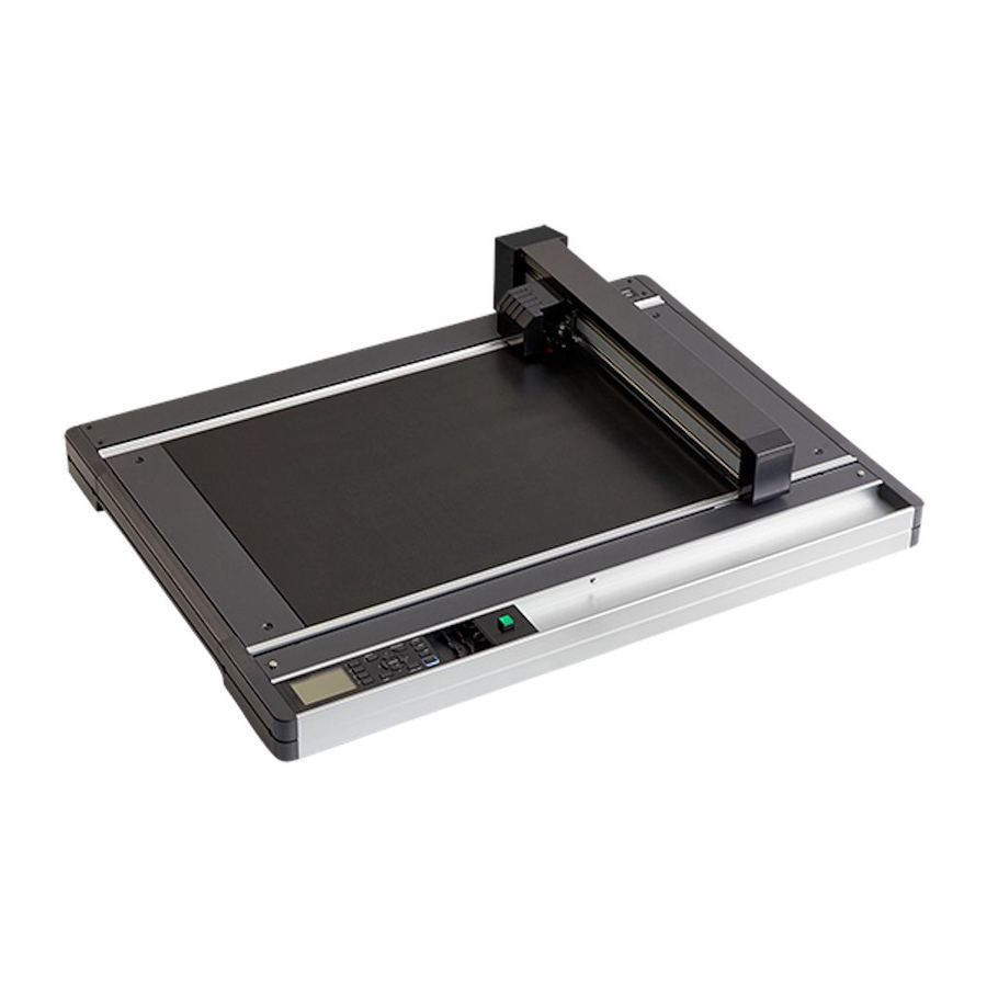
Sign In
Upload
Manuals
Brands
graphtec Manuals
Plotter
FCX4000 SERIES
graphtec FCX4000 SERIES Manuals
Manuals and User Guides for graphtec FCX4000 SERIES. We have
4
graphtec FCX4000 SERIES manuals available for free PDF download: User Manual, Service Manual, Setup Manual
graphtec FCX4000 SERIES User Manual (274 pages)
CUTTING PLOTTER
Brand:
graphtec
| Category:
Plotter
| Size: 5.25 MB
Table of Contents
To Ensure Safe and Correct Use
3
Preface
5
Notes on this Manual
5
Registered Trademarks
5
Copyright
5
Special Precautions on Handling Blades
6
Cutter Blades
6
Cutter Plungers
6
After Mounting the Cutter Pen
6
After Turning on the Cutting Plotter
7
Machine Caution Label
7
Precautions for Electrostatic Panel
7
About the Words and Phrases in this Text
8
Prior to Use
8
Installation Space
9
Warning
10
Federal Communications Commission Radio Frequency Interference Statement
10
Use Shielded Cables
10
Table of Contents
11
Chapter 1: Product Summary
17
Checking The Accessories
18
Accessories
18
Nomenclature
19
Connecting To The Computer
20
Chapter 2: Preparing to Cut
23
Preparation Of Cutter Plunger
24
Cutter Plunger Nomenclature
24
Structure of Cutter Plunger
25
Adjusting the Blade Length
26
Attaching A Tool
27
Removing the Tool
28
How To Use The Control Panel
29
Indicator Lamp
29
Control Key
29
Reading the Screen (LCD)
30
Contents of Operation from Menu Screen
32
Contents of Operation from [COND/TEST] Key
33
Loading The Media
34
Connecting To The Power
35
About The Initial Setup Screen
37
Selecting Tool Condition
38
LCD Display
38
Selecting the Tool Condition Number
38
Setting the Tool Condition
40
Setting the Tool
41
Setting the Creasing Mode
42
Setting the Speed
45
Setting the Force
46
Setting the Acceleration
47
Setting the Assign Tool
48
Adjust the Blade Length
49
Running Cutting Tests
50
Cutting Test
50
To Make 1 Cut with Set Value
50
To Make 3 Cuts with Set Value and ±1 of Set Value
51
Confirm the Results of the Cutting Test
52
Adjustment of Offset
52
Adjustment for Half Cutting
52
Adjustment for Cutting out
52
Adjustment When Using Plotting Pen
52
Adjust the Blade Length (Blade Length Adjustment by the Cutting Plotter)
53
Display Cutting Area
56
Chapter 3: Basic Operations
57
Raise Or Lower The Tool
58
Move The Tool Carriage
59
Move in Steps Manually
59
Continuously Move Manually
59
Setting of Step Movement Distance
60
Move Away the Tool Carriage
61
Change the Cutting Condition (Condition No.)
62
Reset (Revert to the Initial State When the Power was Turned On.)
62
Setting The Origin Point
63
When Coordinate Axes Rotation Are Set
64
Setting Origin Point When HP-GL Is Set
65
Setting The Cutting Direction
66
Pause and Resume Cutting
68
Stop Cutting
68
Stop Cutting
69
Chapter 4: Convenient Functions
71
Settings For Cutting
72
Setting Cutting Area
72
Setting Mirror
74
Set the Enlarge/Shrink Scale (Scale)
75
Copy (Duplicate Cutting)
77
When Cutting Data Has no Registration Mark
77
When Cutting Data Has Registration Marks
79
Dual Configuration
82
Selecting the User
82
Chapter 5: ARMS (Advanced Registration Mark Sensing System)
83
Outline Of Arms
84
Shape (Pattern) of the Registration Mark
84
Scan Range Necessary to Sense the Registration Mark
85
Position of the Origin Point and the Registration Mark
87
Cutting Area When Adjusting the Regisitaration Mark
88
Automatic Sensed of Registration Mark Position
88
Media that Registration Mark Cannot be Sensed
89
Setting And Adjustment Of Arms
90
Setting MARK SCAN MODE and Numbers
90
Setting Shape (Pattern) of Registration Mark
95
Setting Distance Adjustment between the Registration Marks
97
Setting Registration Mark Size
99
Setting Mark Distance
100
Setting Offset between the Registration Mark and Cutting Origin Point
102
Adjusting for the Registration Mark Scan Position
105
Adjust after Plotting the Adjustment Registration Mark
105
Sense the Registration Mark for Adjustment on the Media and Enter the Value
108
Adjusting the Sensor Level
111
Setting the Registration Mark Automatic Sensing
113
Setting Speed of the Registration Mark Scan
114
Setting the Scanning Method When Registration Marks Are Scanned ("ISM"/"NORMAL")
115
Setting Scan Step When Registration Marks Are Scanned
116
Manually Adjusting the Sensor Level (Threshold Value)
118
Test the Registration Mark Sensor
120
Setting The Position Using Arms
122
Adjust with 2 POINTS
122
Adjust with 3 POINTS
124
Adjust with 4 POINTS
125
Adjust Automatically
127
Adjust Manually
128
Chapter 6: Manual Position Adjust
131
Outline Of Manual Position Adjust
132
Setting of MARK SCAN MODE and Number of Adjustment Marks
132
Manual Position Adjust
133
Chapter 7: Setting Regarding Cutting Quality
137
To Cut the Corner of Thick Media Sharply
138
Outline of Tangential Mode
138
Setting the Tangential Mode
139
Setting the Length of Overcut
140
Setting the Initial down Force
142
Setting The Step Pass
144
Setting The Offset Angle
146
Setting The Distance Adjust
148
Setting Cut Line
150
Setting The Initial Blade Angle Position
154
Settings For Offset Force
156
Setting The Overlay Cut Function
157
Setting The Tool Offset Adjust
159
Chapter 8: Settings Regarding Cutting Time
163
Sorting The Cutting Data
164
Setting The Tool Up Move
166
Setting The Tool Up Speed
168
Setting The Tool Up Height
170
Chapter 9: Setting Regarding Interface
173
Setting The Interface
174
USB Interface
174
Network (LAN) Interface
174
RS-232C Interface
175
Clearing The Buffer Memory
176
I/F (Lan)
177
Set the DHCP
177
Set IP Address, Subnet Mask and Gateway
179
When Connecting The Rs-232C Interface
182
Switching Setting Numbers
182
Changing and Storing RS-232C Settings
183
Chapter 10: Setting Regarding Operation Environment
187
Related to Menu Display
188
Display Language Setting (LANGUAGE SELECTION)
188
Setting the Display Length Unit (LENGTH UNIT)
189
Related to Plotter Environment
190
Enabling/Disabling the Beep Setting (BEEP for KEY OPERATION)
190
Setting the Force (SWITCHING XY FORCE)
191
Setting the Position Key Low Speed (POSI. KEY SPEED + SLOW KEY)
192
Setting the Position Key High Speed (POSI. KEY SPEED)
193
Setting the Display of the Position Key (TOOL POSITION)
194
Setting the Pause Key (PAUSE/MENU KEY SETTING)
195
Setting the User Key (USER KEY SETTING)
196
Setting the Draft Mode (DRAFT MODE)
197
Chapter 11: Settings of Controls from Computer
199
Related to Command Processing
200
Setting the Command (COMMAND)
200
Priority of Tool Condition Selection (CONDITION PRIORITY)
201
Enabling/Disabling the Condition Select Command (TOOL SELECT COMMAND)
202
Related to GP-GL Command
203
Setting the Step Size (GP-GL STEP SIZE)
203
Enabling/Disabling the ' : ' and ' ; ' Commands (COMMAND ' : ', ' ; ')
204
Moving the Pen While Raised or Lowered in Response to the 'W' Command (COMMAND 'W')
205
Related to HP-GL Command
206
Model ID Response (HP-GL MODEL EMULATED)
206
Setting the Circle-Command Resolution (CIRCLE RESOLUTION)
207
Chapter 12: Offline Output
209
Offline Output From Usb Memory
210
Output With A Bar Code
212
Chapter 13: Maintenance
215
Daily Maintenance
216
Storing the Cutting Plotter
216
Replacing Cutter Blade
217
Cleaning The Cutter Pen
219
Replacing The Cutter Plunger
220
Setting the Alarm for Degree of Wear (BLADE WEAR ALARM)
221
Chapter 14: Troubleshooting
225
Troubleshooting
226
When the Plotter Does Not Operate after Turning the Power on
226
When It Does Not Work Right
227
When the Cutting Result Is Not Good
228
Error Messages in GP-GL Command Mode
229
Error Messages in HP-GL Command Mode
230
ARMS Error Messages
232
Other Error Messages
235
Caution Message
238
Printing The Setting Of The Cutting Plotter
239
Plotting The Test Pattern
241
Plotting The Cutting Pro
243
Confirming The Cutting Data
245
Plotting The Sample Cut Pattern
247
Self Diagnostic Test
249
Reading the Error Message
250
Appendix
254
External Dimensions
254
Fcx4000-50Es
254
A.1 Main Specifications
254
A.2 Supplies
255
A.3 External Dimensions
256
Fcx4000-60Es
257
FCX4000-60ES (with Option Stand
258
Main Specifications
254
A.4 Menu Tree
259
Menu Tree
259
Default Menu Setting
266
Index
269
Advertisement
GRAPHTEC FCX4000 SERIES Service Manual (197 pages)
Brand:
GRAPHTEC
| Category:
Cutter
| Size: 17.3 MB
Table of Contents
Table of Contents
4
1 Introduction
9
Model Names And Basic Specifications
9
Standard Accessories
9
Main Specifications
10
External Dimensions
11
2 Description Of Parts
13
Plotter Nomenclature
13
Cutter Plunger
14
3 Basic Operation
16
How To Use The Control Panel
16
Menu Tree
20
Replacing The Cutter Blade
27
Adjusting The Blade Length
28
Attaching A Tool
29
About The Initial Setup Screen
30
Selecting Tool Condition
31
Selecting The Tool Condition Number
32
Setting The Tool Condition
33
Running Cutting Tests
36
Cutting Test
36
Confirm The Results Of The Cutting Test
38
4 Daily Maintenance
40
Storing The Plotter
40
Cleaning The Cutter Pen
40
5 Recommended Parts List
42
6 List Of Tools
44
Tools
44
7 Disassembly And Assembly
46
Outer Part
46
Right Front Corner Cover
46
Right Rear Corner Cover
46
Left Front Corner Cover
47
Left Rear Corner Cover
47
Right Top Cover
48
Left Top Cover
48
Right Side Cover
49
Left Side Cover
49
Front Top Cover
50
Rear Top Cover
51
Flexible Cable Cover
52
Rear Bottom Cover
53
Y Bar Cover
55
Pen Block Cover
55
Front Y Bar End Cover
56
Rear Y Bar End Cover
56
Front Bottom Cover
57
Tray Assembly
58
X-Axis Drive Part
60
Motor
60
Motor Belt
62
Front X Belt
65
Rear X Belt
68
Home Sensor Board
71
Flexible Cable
72
Y-Axis Drive Part
76
Y Motor
76
Pen Block Assembly
78
Y Motor Belt
79
Y Home Sensor Board
81
Y Relay Board
82
Pen Board
83
Registration Sensor Boards
84
Y Flexible Cable
85
Y Belt
86
Belt Tension Adjustment
88
Adjusting The X Motor Belt Tension
88
Adjusting The Y Motor Belt Tension
89
Adjusting The Front X Belt Tension
90
Adjusting The Rear X Belt Tension
93
Adjusting The Y Belt Tension
96
Main Board
98
Power Supply Board
99
Fan
100
High Voltage Board
101
Electrostatic Relay Board
101
Motor Power Relay Board
102
Control Panel
103
Control Panel Board
103
Lcd
106
Control Panel Keys
106
Electrostatic Adhesion Switch
107
Electrostatic Adhesion Panel
109
Replacing The Electrostatic Adhesion Panel
109
8 Electrical Adjustments
112
List Of Items Requiring Readjustment
112
Flowchart Of The Adjustment Sequence
113
The Main Board Was Replaced (Normal Procedure)
113
The Main Board was Replaced (if the Adjustment Values Could Not Copy from the SUB-NVRAM.)
114
The Pen Block Was Replaced
115
The X Home Sensor Was Replaced
115
The Y Home Sensor Was Replaced
115
The Registration Mark Sensor Was Replaced
115
The X Or Y Motor Was Replaced
116
The X Or Y Belt Was Replaced
116
Explanation Of The Values Of The Main Board
117
Setting The Dip Switches
118
Updating The System Firmware
119
Clearing The Nv-RAM
121
Selecting Display Language & Length Unit
123
Copying The Adjustment Value Form The Sub-NVRAM
124
Adjusting The Home Position
126
Adjusting The Pen Force
129
Adjusting The Distance And The Perpendicularity Accuracy
133
Adjusting The Tool Interval
138
Adjusting The Registration Mark Sensor Sensitivity
142
Adjusting The Offset Of Registration Mark Sensor
144
Back Up To The Sub-NVRAM
148
Testing The Control Panel Keys And Home Sensors
150
About Start Up Mode
151
9 Troubleshooting
153
The Power Is Not Turned On
153
When It Does Not Work Rightly
154
The Cutting Result Is Not Good
158
Error Messages In Gp-Gl Command Mode
160
Error Messages In Hp-Gl Command Mode
161
Arms Error Messages
163
Hardware Errors
167
Operational Error
171
Caution Message
172
Self Diagnostic Test
173
10 Parts Lists
175
Main Outer
175
Main Frame
176
Drive Section
177
Main Box & Power Box
178
Control Panel
179
Y Bar Outer
180
Y Bar Part
181
Pen Block
183
Wiring Harness
184
Option Stand For The Fcx4000-60
184
Standard Accessories
185
GRAPHTEC FCX4000 SERIES Setup Manual (16 pages)
Cutting Plotter
Brand:
GRAPHTEC
| Category:
Plotter
| Size: 1.12 MB
Table of Contents
Checking the Accessories
2
Before Starting the Setup
3
Setup Flow
3
Attaching a Tool
4
Loading the Media
5
About the Initial Setup Screen
6
Cutting Plotter
9
Advertisement
GRAPHTEC FCX4000 SERIES Setup Manual (12 pages)
CUTTING PLOTTER
Brand:
GRAPHTEC
| Category:
Plotter
| Size: 1.48 MB
Table of Contents
Before Starting the Setup
2
Attaching a Tool
3
Loading the Media
4
About the Initial Setup Screen
5
Installing the Software
7
Advertisement
Related Products
GRAPHTEC FCX2000 SERIES
GRAPHTEC FC7000-75
GRAPHTEC FC7000-130
GRAPHTEC Cutting Pro FC4100-100
GRAPHTEC FC5100A-75
GRAPHTEC FC9000-160
GRAPHTEC CUTTING PRO FC2250-180VC
GRAPHTEC FC8600-160
GRAPHTEC FC4500-50
GRAPHTEC Cutting PRO FC2231-90VCT
graphtec Categories
Plotter
Data Loggers
Scanner
Cutter
Printer
More graphtec Manuals
Login
Sign In
OR
Sign in with Facebook
Sign in with Google
Upload manual
Upload from disk
Upload from URL