GRAPHTEC FCX4000 Service Manual
Hide thumbs
Also See for FCX4000:
- User manual (274 pages) ,
- Setup manual (12 pages) ,
- Setup manual (16 pages)
Table of Contents
Advertisement
Quick Links
Advertisement
Table of Contents

Related Manuals for GRAPHTEC FCX4000


Summary of Contents for GRAPHTEC FCX4000
- Page 1 CUTTING MACHINE FCX4000 FCX4000-UM-251-02-9370 SERVICE MANUAL...
- Page 3 The parts number for Y Belt 60 was corrected. 18.3.09 The parts number for X Flexible Cable FFC403104 was corrected. 5-1,10-7,10-10 18.3.09 The parts number for X Flexible Cable, FFC403102 was corrected. 5-1,10-7,10-10 "a10,1.Axxxxxxxxx” was corrected to "a10,1,Axxxxxxxxx”. 18.3.09 8-37 FCX4000-UM-251-9370...
-
Page 4: Table Of Contents
3.7 Selecting Tool Condition ................3-16 3.7.1 Selecting the tool condition number ....................3-17 3.7.2 Setting the Tool Condition ........................3-18 3.8 Running Cutting Tests ...................3-21 3.8.1 Cutting Test ............................3-21 3.8.2 Confirm the Results of the Cutting Test ....................3-23 4 Daily Maintenance ............4-1 4.1 Daily Maintenance ....................4-1 4.2 Storing the Plotter ....................4-1 4.3 Cleaning the Cutter Pen ...................4-1 5 RECOMMENDED PARTS LIST........5-1 6 LIST OF TOOLS .............6-1 Tools ........................6-1 FCX4000-UM-251-9370... - Page 5 7.3 Y-Axis Drive Part .....................7-31 7.3.1 Y Motor ..............................7-31 7.3.2 Pen Block Assembly ..........................7-33 7.3.3 Y Motor Belt ............................7-34 7.3.4 Y Home Sensor Board ........................... 7-36 7.3.5 Y Relay Board ............................7-37 7.3.6 Pen Board ............................... 7-38 7.3.7 Registration Sensor Boards ......................... 7-39 7.3.8 Y Flexible Cable ............................. 7-40 7.3.9 Y Belt ............................... 7-41 FCX4000-UM-251-9370...
- Page 6 8.2.4 The X home sensor was replaced ......................8-4 8.2.5 The Y home sensor was replaced ......................8-4 8.2.6 The registration mark sensor was replaced ..................8-4 8.2.7 The X or Y motor was replaced ......................8-5 8.2.8 The X or Y belt was replaced ........................8-5 8.3 Explanation of the Values of the Main Board ..........8-6 8.4 Setting the DIP Switches ..................8-7 8.5 Updating the System Firmware ...............8-8 8.6 Clearing the NV-RAM ..................8-10 8.7 Selecting Display Language & Length Unit ..........8-12 8.8 Copying the Adjustment value form the SUB-NVRAM ........8-13 8.9 Adjusting the Home Position .................8-15 FCX4000-UM-251-9370...
- Page 7 9.9 Caution Message ....................9-20 9.10 Self Diagnostic Test ..................9-21 10. PARTS LISTS ...............10-1 10.1 Main Outer .......................10-1 10.2 Main Frame ......................10-2 10.3 X Drive Section ....................10-3 10.4 Main Box & Power Box ...................10-4 10.5 Control Panel ....................10-5 10.6 Y Bar Outer ......................10-6 10.7 Y Bar Part ......................10-7 10.8 Pen Block ......................10-9 10.9 Wiring Harness .....................10-10 10.10 Option Stand for the FCX4000-60 ..............10-10 10.11 Standard Accessories ..................10-11 FCX4000-UM-251-9370...
- Page 8 11 BLOCK DIAGRAMS .............11-1 12 Target electrical component for WEEE instruction .12-1 FCX4000-UM-251-9370...
-
Page 9: Introduction
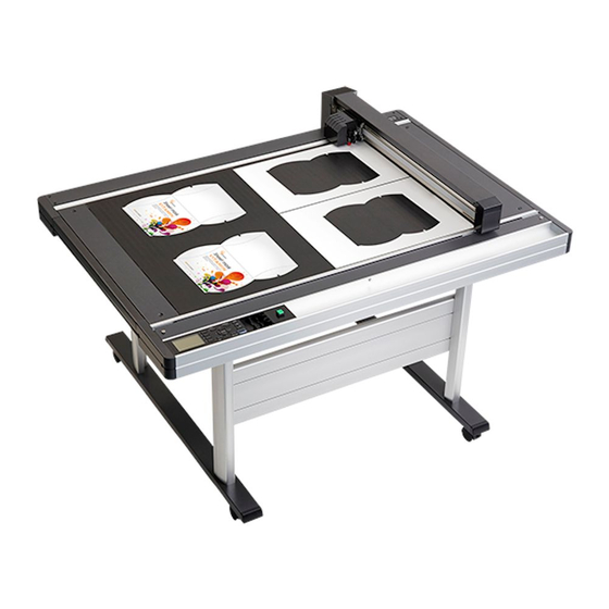
CAUTION DOUBLE POLE/NEUTRAL FUSING Model Names and Basic Specifications Model Media hold down method Cutting area Mountable media width FCX4000-50ES 660 (X) x 488 (Y) mm 536 mm Electrostatic adhesion FCX4000-60ES 976 (X) x 660 (Y) mm 708 mm Standard Accessories Item Q’ty... -
Page 10: Main Specifications
INTRODUCTION Main Specifications FCX4000-50ES FCX4000-60ES Configuration Flatbed Drive system Digital servo Media hold-down method Electrostatic adhesion Effective cutting area 660 x 488 mm 976 x 660 mm Mountable media (Y-axis) 536 mm 708 mm Maximum cutting speed 75 cm/sec (Omnidirection) Max. -
Page 11: External Dimensions
INTRODUCTION External Dimensions FCX4000-50ES 1089 Unit: mm Dimensional accuracy: ±5mm FCX4000-60ES 1405 Unit: mm Dimensional accuracy: ±5mm FCX4000-UM-251-9370... - Page 12 INTRODUCTION FCX4000-60ES with Stand 1405 Unit: mm Dimensional accuracy: ±5mm FCX4000-UM-251-9370...
-
Page 13: Description Of Parts
(9) RS-232C interface connector ....Used to connect the plotter to the computer with a RS-232C interface cable. (10) Network (LAN) interface connector ..The connector used when connecting this plotter with the network (LAN)interface cable. (11) USB memory dedicated port ....The port that is used only for the USB memory. FCX4000-UM-251-9370... -
Page 14: Cutter Plunger
Structure of Cutter Plunger PHP33-CB09N-HS/ PHP35-CB09-HS/ PHP33-CB15N-HS PHP35-CB15-HS Blade-length adjustment knob Blade-length adjustment knob (Blue) / (Red) Plunger Plunger Cutter blade Cutter blade φ0.9 mm / φ1.5 mm φ0.9 mm / φ1.5 mm Plunger-cap Chuck (Blue) / (Red) Plunger-cap Hole Hole FCX4000-UM-251-9370... - Page 15 Description of Parts FCX4000-UM-251-9370...
-
Page 16: Basic Operation
On the READY screen, pressing the [ENTER] and [ORIGIN] keys at the same time will allow you to reset the machine. COND/TEST ......Displays the screen to set the tool conditions. Use this when checking tool conditions to activate a cutting test. FCX4000-UM-251-9730... - Page 17 : Mirror Corresponding button name of control panel R90 Mir : Mirror & Rotate (Valid button is displayed in reverse) Priority : MANUL : Manual priority PROGRA : Pogram priority Sort : Sort ON : Display when sort is on FCX4000-UM-251-9730...
- Page 18 Page number is displayed in the upper right corner of the screen if there are many settings or selection that will need multiple pages to display. Press the POSITION ( , , , ) key to move to different page. Page number [3] key POSITION ( Page number Example of moving page and operation button FCX4000-UM-251-9730...
- Page 19 : It will close the MENU screen and return to default screen. [SLOW] : Displays the position key screen. When media is set, the tool position can be moved. See the “Menu Tree” for list of the descriptions about each settings. FCX4000-UM-251-9730...
-
Page 20: Menu Tree
3. OPERATIONS Menu Tree Default screen CONDITION setting screen (1/4) [COND/TEST] [ENTER] [COPY] CONDITION setting screen (2/4) CONDITION setting screen (3/4) CONDITION Continued setting screen (4/4) FCX4000-UM-251-9730... - Page 21 3. OPERATIONS Default screen CONDITION (Continued) setting screen (3/4) CONDITION SETTING screen (4/4) TOOLS MENU screen SETTING screen (1/4) [PAUSE/MENU] TOOLS SETTING screen (2/4) TOOLS SETTING screen (3/4) TOOLS Continued setting screen (4/4) FCX4000-UM-251-9730...
- Page 22 3. OPERATIONS Default screen TOOLS (Continued) SETTING screen (4/4) TOOLS SETTING screen (4/4) ARMS MENU screen SETTING screen (1/5) [PAUSE/MENU] ARMS SETTING screen (2/5) ARMS SETTING screen (3/5) ARMS Continued SETTING screen (4/5) FCX4000-UM-251-9730...
- Page 23 3. OPERATIONS Default screen ARMS (Continued) SETTING screen (3/5) ARMS SETTING screen (4/5) ARMS SETTING screen (5/5) AREA MENU screen SETTING screen (1/2) [PAUSE/MENU] AREA SETTING screen (2/2) Continued FCX4000-UM-251-9730...
- Page 24 3. OPERATIONS Default screen (Continued) INTERFACE MENU screen setting screen (1/3) [PAUSE/MENU] INTERFACE setting screen (2/3) INTERFACE setting screen (3/3) ADVANCE MENU screen setting screen (1/3) [PAUSE/MENU] ADVANCE Continued setting screen (2/3) FCX4000-UM-251-9730...
- Page 25 3. OPERATIONS Default screen ADVANCE (Continued) setting screen (1/3) ADVANCE setting screen (2/3) ADVANCE setting screen (3/3) TEST MENU screen setting screen (1/2) [PAUSE/MENU] TEST setting screen (2/2) Continued FCX4000-UM-251-9730 3-10...
- Page 26 3. OPERATIONS Default screen (Continued) MEM. MENU screen setting screen (1/1) [PAUSE/MENU] Default screen (Finish) FCX4000-UM-251-9730 3-11...
-
Page 27: Replacing The Cutter Blade
Push the blade hole part several times when the blade was not able to install to the chuck straightly. And then install the blade to the chuck completely. Blade hole part (3) Install the chuck to the plunger after the blade was replaced. Then tighten the chuck. FCX4000-UM-251-9730 3-12... -
Page 28: Adjusting The Blade Length
Try cutting the film, and adjust so there is slight cutting on the backing sheet. If the backing sheet gets cut completely, reduce the blade length, and if the film does not get cut completely, increase the blade length. Optimal blade length Film Thickness of Media Backing Sheet FCX4000-UM-251-9730 3-13... -
Page 29: Attaching A Tool
Tool Bracket to hold tool Flange Tool holder (3) Make sure that the tool bracket is engaged on the tool's flange, and then tighten the screw. Bracket to hold tool Flange Tool holder screw FCX4000-UM-251-9730 3-14... -
Page 30: About The Initial Setup Screen
(4) Press the [1] key (METRIC) or the [2] key (INCH) to select the length unit setting. (5) Confirm the setting and press the [ENTER] key (SET). (6) Setting will be set, and it will return to default screen. FCX4000-UM-251-9730 3-15... -
Page 31: Selecting Tool Condition
3. OPERATIONS Selecting Tool Condition Set the “TOOL CONDITION (Cut Condition) No.”, “TOOL”, “OFFSET”, “FORCE”, “SPEED”, and “ACCEL (ACCELERATION)”. Tool condition number that is currently being used Selected condition User number FCX4000-UM-251-9730 3-16... -
Page 32: Selecting The Tool Condition Number
(2) Select the CUT CONDITION (Tool Condition) by pressing one of [1] to [4] key or using the POSITION (▲▼▲▼) keys while holding down the [ENTER] key. (The selected item is highlighted.) (3) Confirm the setting and release the [ENTER] key. It will return to default screen. FCX4000-UM-251-9730 3-17... -
Page 33: Setting The Tool Condition
(5) Press the POSITION (▲▼) keys and increase or decrease the setting value. (6) Confirm the setting and press the [ENTER] key (SET). Setting will be set, and it will return to CONDITION screen (1/4). (7) Press the [COND/TEST] key. It will return to default screen. FCX4000-UM-251-9730 3-18... - Page 34 (2) Press the [4] key (FORCE). FORCE setting screen is displayed. (3) Press the POSITION ( ) keys and select the condition number (CONDITION No.) (4) PPress the POSITION (▲▼) keys and increase or decrease the setting value. FCX4000-UM-251-9730 3-19...
- Page 35 (5) Press the POSITION (▲▼) keys and increase or decrease the setting value. (6) Confirm the setting and press the [ENTER] key (SET). Setting will be set, and it will return to CONDITION screen (2/4). (7) Press the [COND/TEST] key. It will return to default screen. FCX4000-UM-251-9730 3-20...
-
Page 36: Running Cutting Tests
It will return to default screen To make 3 cuts with set value and ±1 of set value (1) Load the media for test cutting in the plotter. (2) Press the [COND/TEST] key in the default screen. CONDITION setting screen (1/4) is displayed. FCX4000-UM-251-9730 3-21... - Page 37 3 cutting test patterns are cut, with current CUTTER OFFSET in the center, and 1 each of CUTTER OFFSET increased and decreased for 1. (8) Press the [ENTER] key after completion. It will return to CUT TEST menu screen. (9) Press the [COND/TEST] key. It will return to default screen. FCX4000-UM-251-9730 3-22...
-
Page 38: Confirm The Results Of The Cutting Test
The offset is pre-set to the each blade type. Confirm the blade type first. At this time the thick diameter of blade is installed and the thin diameter of blade type is selecting. Increase the offset value when the correct blade type is selecting. FCX4000-UM-251-9730 3-23... - Page 39 If the media is not completely cut, either the FORCE setting is too low or the cutter blade length is not sufficiently extended. Adjustment When Using Plotting Pen Adjust the FORCE so there will be no faint lines. To prolong the pen life, set the FORCE to the lowest setting without any faint lines. FCX4000-UM-251-9730 3-24...
-
Page 40: Daily Maintenance
(1) Clean off paper dust and media build up from the blade. After cleaning it, return it to its proper place. Spin the plunger cap, remove it, and then clean the blade entrance area. PHP33-CB09N-HS/ PHP35-CB09-HS/ PHP33-CB15N-HS PHP35-CB15-HS Plunger Plunger Cutter blade Cutter blade Plunger cap Chuck Cleaning Cleaning (2) Attach the plunger cap after the cleaning is finished. FCX4000-UM-251-9730... - Page 41 Daily Maintenance FCX4000-UM-251-9730...
-
Page 42: Recommended Parts List
Same as FCX2000 U792200710 Control Panel Board, FCX2000 Same as FCX2000 U682157130 LCD, BTG240128SFBWBGG U792260314 X Flexible Cable, FFC403104 FCX4000-50, Same as FCX2000-60 U792260341 X Flexible Cable, FFC403102 FCX4000-60, Same as FCX2000-120 U692265314 Y Flexible Cable, FCC601201D U792400720 Pen Block Assembly, FCX4000... -
Page 44: List Of Tools
25 Double-sided tape (10 mm wide) For securing the FPC cables 26 Ethyl alcohol For cleaning the electrostatic adhesion plate and rail 27 Silicon grease (Shinetsu Silicon grease G-501) Belt 28 Albania Grease AS2 (Showa Shell) Gear, Shaft Bearing FCX4000-UM-251-9730... -
Page 46: Disassembly And Assembly
(1) Remove the two M4L8 binding head screws holding the right rear corner cover, and then detach it. Right rear corner cover M4L8 binding head screw How to reinstall the Right Rear Corner Cover (1) Reattach the right rear corner cover in the reverse order in which it was detached. FCX4000-UM-251-9370... -
Page 47: Left Front Corner Cover
(1) Remove the two M4L8 binding head screws holding the left rear corner cover, and then detach it. Left rear corner cover M4L8 binding head screw How to reinstall the Left Rear Corner Cover (1) Reattach the left rear corner cover in the reverse order in which it was detached. FCX4000-UM-251-9370... -
Page 48: Right Top Cover
(1) Remove the two M4L8 binding head screws holding the left top cover, and then detach it. M4L8 binding head screw Left top cover How to reinstall the Left Top Cover (1) Reattach the left top cover in the reverse order in which it was detached. FCX4000-UM-251-9370... -
Page 49: Right Side Cover
(4) Remove the seven M4L8 binding head screws holding the left side cover, and then detach it. M4L8 binding head screw Left side cover M4L8 binding head screw How to reinstall the Left Side Cover (1) Reattach the left side cover in the reverse order in which it was detached. FCX4000-UM-251-9370... -
Page 50: Front Top Cover
(1) Remove the three M4L6 thumb screws holding the front top cover. M4L6 thumb screw Front top cover M4L6 thumb screw How to reinstall the Front Top Cover (1) Reattach the front top cover in the reverse order in which it was detached. FCX4000-UM-251-9370... -
Page 51: Rear Top Cover
7.1.10 Rear Top Cover How to detach the Rear Top Cover (1) Remove the eight M4L8 binding head screws holding the rear top cover for the FCX4000-60, and then detach it. Remove the seven M4L8 binding head screws holding the rear top cover for the FCX4000-50, and then detach it. -
Page 52: Flexible Cable Cover
(1) Remove the two M4L8 binding head screws holding the X flexible cable cover, and then detach it. X flexible cable cover M4L8 binding head screw How to reinstall the X Flexible Cable Cover (1) Reattach the X flexible cable cover in the reverse order in which it was detached. FCX4000-UM-251-9370... -
Page 53: Rear Bottom Cover
X Flexible cable Cable tie (7) Remove the five M4L8 binding head screws holding the bottom of rear bottom cover for the FCX4000- Remove the three M4L8 binding head screws holding the bottom of rear bottom cover for the FCX4000- (8) Remove the four M4L8 flange cap screws holding the each side of rear bottom cover. - Page 54 DISASSEMBLY AND ASSEMBLY How to reinstall the Rear Bottom Cover (1) Reattach the rear bottom cover in the reverse order in which it was detached. (2) Detach the front bottom cover. FCX4000-UM-251-9370...
-
Page 55: Y Bar Cover
How to reinstall the Pen Block Cover (1) Reattach the pen block cover in the reverse order in which it was detached. (2) Take care that cables are not caught between an pen block and a pen block cover when reinstalling the cover. FCX4000-UM-251-9370 7-10... -
Page 56: Front Y Bar End Cover
Rear Y bar end cover M3L6 binding head screw M3L6 binding head screw How to reinstall the Rear Y Bar End Cover (1) Reattach the rear Y bar end cover in the reverse order in which it was detached. FCX4000-UM-251-9370 7-11... -
Page 57: Front Bottom Cover
7.1.17 Front Bottom Cover How to detach the Front Bottom Cover (1) Remove the thirteen M4L8 binding head screws holding the front bottom cover for the FCX4000-60. Remove the ten M4L8 binding head screws holding the front bottom cover for the FCX4000-50. -
Page 58: Tray Assembly
(10) Release the cable ties holding the cables, and then pull out the cable from the left side main frame. Pull out the cables from here. Cable tie (11) Disconnect the ES power cable from the relay connector of the ES high voltage board. ES power cable FCX4000-UM-251-9370 7-13... - Page 59 (13) Remove the eight M4L14 flange cap screws holding the tray assembly, and then detach it. M4L14 flange cap screw Tray assembly M4L14 flange cap screw How to reinstall the Tray Assembly (1) Reattach the tray assembly in the reverse order in which it was detached. FCX4000-UM-251-9370 7-14...
-
Page 60: X-Axis Drive Part
M3L6 flange cap screw (5) Detach the core from the X motor encoder cable. (6) Loosen the two M3L5 set screws holding the X motor pulley, and then detach it. M3L5 set screw X motor X motor pulley FCX4000-UM-251-9370 7-15... - Page 61 (2) Reattach the X motor in the reverse order in which it was detached. (3) Adjust the X motor belt tension when installing the X motor (Refer to the section 7.4.1.). (4) Apply a few quantity of the silicon grease to the belt and the tooth of pulley. FCX4000-UM-251-9370 7-16...
-
Page 62: Motor Belt
Mark the position of X rear belt tension bracket. Rear X belt tension bracket (9) Loosen the two M4L6 binding head screws fixing from the bottom of rear X rear belt tension bracket. Access the screws from these holes. FCX4000-UM-251-9370 7-17... - Page 63 (14) Loosen the four M4L5 set screws holding the rear X drive pulley, and then detach it from the X drive shaft. M4L5 set screw X drive shaft Rear X drive pulley (15) Detach the bearing from the rear frame. FCX4000-UM-251-9370 7-18...
- Page 64 (2) Adjust the X motor belt tension when installing the X motor (Refer to the section 7.4.1.). (3) Tighten the rear X belt tension adjustment screws until the marked tension position after the rear X belt was installed. FCX4000-UM-251-9370 7-19...
-
Page 65: Front X Belt
(7) Mark the position of X belt tension bracket before loosing the screws of the X belt tension bracket as shown in the picture below. Mark the position of X front belt tension bracket. Front X belt tension bracket Mark the position of Front X belt tension bracket. Front X belt tension bracket FCX4000-UM-251-9370 7-20... - Page 66 Remove the four M3L10 binding head screws holding the belt stoppers, and then detach the front X belt from the front X slider and the pulleys. Belt stopper Front X belt M3L10 binding head screw Access the screws from these holes. FCX4000-UM-251-9370 7-21...
- Page 67 (6) Adjust the Y bar angle to be parallel from the left edge of honeycomb plate. The left side edge of honeycomb plate Left edge of Y bar (7) Tighten the four M4L5 set screws holding the front X drive pulley. FCX4000-UM-251-9370 7-22...
-
Page 68: Rear X Belt
(8) Mark the position of X belt tension bracket before loosing the screws of the X belt tension bracket as shown in the picture below. Mark the position of X rear belt tension bracket. Rear X belt tension bracket Mark the position of rear X belt tension bracket. Rear X belt tension bracket FCX4000-UM-251-9370 7-23... - Page 69 Remove the four M3L10 binding head screws holding the belt stoppers, and then detach the rear X belt from the rear X slider and the pulleys. Rear X belt M3L10 binding head screw Access the screws from these holes. FCX4000-UM-251-9370 7-24...
- Page 70 (6) Adjust the Y bar angle to be parallel from the left edge of honeycomb plate. The left side edge of honeycomb plate Left edge of Y bar (7) Tighten the four M4L5 set screws holding the rear X drive pulley. FCX4000-UM-251-9370 7-25...
-
Page 71: Home Sensor Board
X home sensor. Confirm the X home sensor dog is not hitting to the X home sensor. X home sensor X home sensor dog (4) Adjust the home position in the maintenance mode, after the X home sensor was reinstalled. FCX4000-UM-251-9370 7-26... -
Page 72: Flexible Cable
Rear Y bar lower plate (5) Detach the rear Y bar lower plate from Y bar. (6) Remove the three M3L3 binding head screws holding the X Flexible Cable Bracket, and then detach it. X flexible cable bracket M3L3 binding head screw FCX4000-UM-251-9370 7-27... - Page 73 Valley fold with right angle Mountain fold with right angle Reinforcement plate Valley fold Valley fold This side has This side has contact terminal. contact terminal. 45 degree 45 degree 45 degree 110 mm 160 mm 254mm 295mm 320 mm FCX4000-UM-251-9370 7-28...
- Page 74 (3) Put the three double-sided tapes to as shown in the following picture. X flexible cable holder Rear bottom cover FCX4000-50: 560 mm FCX4000-60: 650 mm (4) Reattach the X flexible cable in the reverse order in which it was detached.
- Page 75 (6) Move the Y bar to the end of right side. (7) Make the 10 mm slack on the left side of Y flexible cable holder. X flexible cable holder (8) Put the X flexible cable to the rear bottom cover by using the two double-sided tapes. FCX4000-UM-251-9370 7-30...
-
Page 76: Y-Axis Drive Part
(3) Remove the Three M3L6 binding head screws holding the Y motor assembly, and then detach it. M3L6 binding head screw (4) Remove the Three M3L6 binding head screws holding the Y motor bracket, and then detach it. Y motor Y motor bracket M3L6 binding head screw FCX4000-UM-251-9370 7-31... - Page 77 (2) Install the Y motor pulley to motor shaft as shown in the picture below. 2 mm (3) Adjust the Y motor belt tension when installing the Y motor (Refer to the section 7.4.2.). (4) Apply a few quantity of the silicon grease to the belt and the tooth of pulley. FCX4000-UM-251-9370 7-32...
-
Page 78: Pen Block Assembly
(2) Install the pen block assembly to 10 mm height from the writing panel. 10 mm (3) Adjust the tool force when the pen block assembly was replaced. (4) Adjust the registration mark sensor positions when the registration sensor boards were removed. FCX4000-UM-251-9370 7-33... -
Page 79: Y Motor Belt
Y belt tension adjustment screws (8) Remove the two M3L4 binding head screws holding the Y belt stopper plate with the Y bel. Y belt M3L4 binding head screw Y belt stopper plate (9) Detach the Y belt from the Y slider. FCX4000-UM-251-9370 7-34... - Page 80 (2) Adjust the Y motor belt tension when installing the Y motor (Refer to the section 7.4.2.). (3) Adjust the Y belt tension when installing the Y belt (Refer to the section 7.4.5.). (4) Apply a few quantity of the silicon grease to the belt and the tooth of pulley. FCX4000-UM-251-9370 7-35...
-
Page 81: Y Home Sensor Board
Y home sensor. Y home sensor dog Y home sensor Confirm the Y home sensor dog is not hitting to the Y home sensor. (4) Adjust the home position in the maintenance mode, after the Y home sensor was reinstalled. FCX4000-UM-251-9370 7-36... -
Page 82: Y Relay Board
(3) Remove the two M3L6 binding head screws holding the Y relay board, and then detach it. How to reinstall the Y Relay Board (1) Reattach the Y relay board in the reverse order in which it was detached. FCX4000-UM-251-9370 7-37... -
Page 83: Pen Board
(3) Adjust the Y home sensor dog or the Y home sensor board position if the Y home sensor dog is hitting to the Y home sensor. (4) Adjust the home position in the maintenance mode, after the Y home sensor dog was reinstalled. FCX4000-UM-251-9370 7-38... -
Page 84: Registration Sensor Boards
(1) Reattach the registration sensor boards in the reverse order in which they were detached. (2) Adjust the registration mark sensor sensitivity when the registration sensor boards were replaced. (3) Adjust the registration mark sensor positions when the registration sensor boards were removed. FCX4000-UM-251-9370 7-39... -
Page 85: Y Flexible Cable
(2) Move the pen block to front end of Y bar until it hit to the front stopper. 5 mm (3) Make the 5 mm slack between the turning end of Y flexible cable and the pen board as shown in above picture. FCX4000-UM-251-9370 7-40... -
Page 86: Y Belt
(7) Remove the four M3L4 binding head screws holding the Y belt stopper plates with the Y bel. M3L4 binding head screw Y slider Y belt Y belt stopper plate (8) Detach the Y belt from the Y slider. FCX4000-UM-251-9370 7-41... - Page 87 (2) Reattach the Y belt in the reverse order in which it was detached. (3) Adjust the Y belt tension when installing the Y belt (Refer to the section 7.4.5.). (4) Apply a few quantity of the silicon grease to the belt and the tooth of pulley. FCX4000-UM-251-9370 7-42...
-
Page 88: Belt Tension Adjustment
(3) Push the X motor pulley with a 5 kgf push-pull gauge as shown in the picture below. X Motor Push-Pull tension gauge (4) Adjust the belt tension to be 1.3 kgf +/- 0.2, then tighten the three M3L6 flange cap screws. FCX4000-UM-251-9370 7-43... -
Page 89: Adjusting The Y Motor Belt Tension
(3) Pull the Y motor assembly with a 5 kgf push-pull gauge as shown in the picture below. Y Motor bracket Push-Pull tension gauge Push-Pull tension gauge (4) Adjust the belt tension to be 1.3 kgf +/- 0.2, then tighten the three M3L6 binding head screws. FCX4000-UM-251-9370 7-44... -
Page 90: Adjusting The Front X Belt Tension
(8) Adjust the belt tension by the two belt tension adjustment screws from the access holes which are shown in the following picture. Use these access holes to loosen the X belt tension. * Turn the screws to clockwise to tighten the belt tension. * Turn the screws to counterclockwise to loosen the belt tension. FCX4000-UM-251-9370 7-45... - Page 91 Press down the X belt at center of belt by push pull gauge. Front or rear X rails 8 mm Scale X belt (12) Adjust the belt tension to be the following table of tension. FCX4000-50 FCX4000-60, 420g to 440g 290g to 310g FCX4000-UM-251-9370 7-46...
- Page 92 The other grease will be the cause of chemical damage to the belt. (16) Tighten the two M4L6 binding head screw fixing the front X belt tension bracket. Access the screws from these holes. Front X belt tension bracket M4L6 binding head screws fixing front X belt tension. FCX4000-UM-251-9370 7-47...
-
Page 93: Adjusting The Rear X Belt Tension
(12) Loosen the two M4L6 binding head screw fixing the idler bracket. Idler bracket Idler bracket Rear X belt M4L6 binding head screw M4L6 binding head screw Rear X belt Use this access hole to loosen the screw of front. FCX4000-UM-251-9370 7-48... - Page 94 Push down X belt 8 mm from horizontal position of belt, and then measure the belt tension. Press down the X belt at center of belt by push pull gauge. Front or rear X rails 8 mm Scale X belt FCX4000-UM-251-9370 7-49...
- Page 95 DISASSEMBLY AND ASSEMBLY (17) Adjust the belt tension to be the following table of tension. FCX4000-50 FCX4000-60, 420g to 440g 290g to 210g (18) Move the Y bar to the far right and the far left several times, and then confirm the X belt is not touching to the flange of X idler pulley.
-
Page 96: Adjusting The Y Belt Tension
Pull the Y belt at center of belt by push pull gauge. Front or rear Y rails 10 mm Scale Y belt (7) Adjust the belt tension to be the following table of tension. FCX4000-50 FCX4000-60, 790g to 830g 610g to 650g FCX4000-UM-251-9370 7-51... - Page 97 (10) Apply a few quantity of the silicon grease to the Y drive pulley if the belt was replaced. Note: Do not use grease other than the silicon-grease. The other grease will be the cause of chemical damage to the belt. FCX4000-UM-251-9370 7-52...
-
Page 98: Main Board
(5) Remove the studs from the main board. Stud How to reinstall the main board (1) Reattach the main board in the reverse order in which it was detached. (2) Adjust the electrical adjustment (See section 8). FCX4000-UM-251-9370 7-53... -
Page 99: Power Supply Board
(3) Remove the four M3L6 binding head screws holding the power supply board, then detach it. Power supply board M3L6 binding head screw How to reinstall the power supply board (1) Reattach the power supply board in the reverse order in which it was detached. FCX4000-UM-251-9370 7-54... -
Page 100: Fan
(4) Remove the two M3L28 binding head screws holding the fan, then detach it. M3L28 binding head screw Fan bracket How to reinstall the Fan (1) Reattach the fan in the reverse order in which it was detached. FCX4000-UM-251-9370 7-55... -
Page 101: High Voltage Board
M3L6 binding head screw Electrostatic panel flexible cable Electrostatic relay board Electrostatic relay connector High voltage board How to reinstall the Electrostatic Relay Board (1) Reattach the electrostatic relay board in the reverse order in which it was detached. FCX4000-UM-251-9370 7-56... -
Page 102: Motor Power Relay Board
(3) Remove the three M3L6 binding head screws holding the motor power relay board, and then detach it. Motor power relay board M3L6 binding head screw How to reinstall the Motor Power Relay Board (1) Reattach the motor power relay board in the reverse order in which it was detached. FCX4000-UM-251-9370 7-57... -
Page 103: Control Panel
(3) Detach the front bottom cover (Refer to the section 7.1.17.). (4) Remove the three M4L10 self-tapping screws holding the control panel assembly. M4L10 self-tapping screw (5) Pull out the control panel assembly from the tray. Control panel assembly FCX4000-UM-251-9370 7-58... - Page 104 (7) Remove the six M3L6 self-tapping screws holding the control panel bottom cover, and the detach it. Control panel bottom cover M3L6 self-tapping screw (8) Disconnect the LCD flexible cable from the control panel board. Control panel board LCD flexible cable FCX4000-UM-251-9370 7-59...
- Page 105 (9) Remove the six M2L5 self-tapping screws holding the control panel board, and the detach it. Control panel board M2L5 self-tapping screw How to reinstall the control panel board (1) Reattach the control panel board in the reverse order in which it was detached. FCX4000-UM-251-9370 7-60...
-
Page 106: Lcd
7.7.2 How to detach the LCD (1) Detach the control panel board (Refer to the section 7.7.1.). (2) Slide out the LCD to the left from the control cover which is holding by hook of control panel cover, and then detach it. Hook How to reinstall the LCD (1) Reattach the LCD in the reverse order in which it was detached. -
Page 107: Electrostatic Adhesion Switch
Pull out the cables from here. Cable tie (7) Remove the two M3L6 binding head screws holding the Electrostatic Adhesion Switch assembly, and then detach it from the tray. Electrostatic Adhesion Switch assembly M3L6 binding head screw FCX4000-UM-251-9370 7-62... - Page 108 Nut of Electrostatic Adhesion Switch Electrostatic Adhesion Switch Electrostatic Adhesion Switch Bracket How to reinstall the Electrostatic Adhesion Switch (1) Reattach the Electrostatic Adhesion Switch in the reverse order in which it was detached. FCX4000-UM-251-9370 7-63...
-
Page 109: Electrostatic Adhesion Panel
(3) Move the Y bar to the left end. (4) Disconnect the flexible cable of electrostatic adhesion panel from the electrostatic relay board. (5) Gently peel off the electrostatic adhesion panel from the honeycomb plate at the flexible cable of electrostatic adhesion panel. FCX4000-UM-251-9370 7-64... - Page 110 (6) Remove all double-sided Adhesion tapes from the electrostatic relay board. (The Electrostatic Adhesion Panel is holding by the double-sided Adhesion tapes with all parts of Electrostatic Adhesion Panel when the FCX4000 was shipped from factory as shown in the picture below.)
- Page 111 And then have the 2 mm gap to the each double-sided Adhesion tapes. (3) Put on the electrostatic adhesion panel to the honeycomb plate from the left side of FCX4000 during gently removing the protection label from double-sided Adhesion tapes. FCX4000-UM-251-9370...
-
Page 112: Electrical Adjustments
Firmware upgrade Pen height adjustment Pen force adjustment Distance adjustment Home position adjustment Pen interval adjustment Registration mark sensor adjustment Belt tension adjustment No mark: Adjustment unnecessary M: Must always be adjusted N: To be adjusted as necessary Note: The main board must have the latest version of firmware unless otherwise specified. FCX4000-UM-251-9370... -
Page 113: Flowchart Of The Adjustment Sequence
ELECTRICAL ADJUSTMENTS Flowchart of the Adjustment Sequence Flowchart of the Adjustment Sequence for the FCX4000 series. 8.2.1 The main board was replaced (Normal procedure) When the main board was exchanged, copy adjustment values to the main board from the SUB-NVRAM by the following procedure. -
Page 114: The Main Board Was Replaced (If The Adjustment Values Could Not Copy From The Sub-Nvram.)
8.11 Adjusting the Distance and the Perpendicularity Accuracy 8.12 Adjusting the Tool Interval 8.13 Adjusting the Registration Mark Sensor Sensitivity 8.14 Adjusting the Offset of Registration Mark Sensor 8.15 Back up to the SUB-NVRAM End of Main Board replacement FCX4000-UM-251-9370... -
Page 115: The Pen Block Was Replaced
End of Adjustment 8.2.6 The registration mark sensor was replaced When the registration mark sensor was exchanged, perform the following adjustments. 8.13 Adjusting the Registration Mark Sensor Sensitivity 8.14 Adjusting the Offset of Registration Mark Sensor End of Adjustment FCX4000-UM-251-9370... -
Page 116: The X Or Y Motor Was Replaced
The X or Y belt was replaced When the X or Y belt was exchanged, an electric adjustment is executed by the following procedure. 8.9 Adjusting the Home Position 8.11 Adjusting the Distance and the Perpendicularity Accuracy End of Adjustment FCX4000-UM-251-9370... -
Page 117: Explanation Of The Values Of The Main Board
You can input the same values when you have replaced the main board without making any adjustments except the registration sensor level adjustments. If you have changed any values by making adjustments, record those values for the next maintenance check. FCX4000-UM-251-9370... -
Page 118: Setting The Dip Switches
This setting depends on the model. Dip Switch Model OFF OFF OFF OFF OFF OFF OFF OFF FCX4000-50 1 2 3 4 5 6 7 8 ON OFF OFF OFF OFF OFF OFF OFF FCX4000-60 1 2 3 4 5 6 7 8 Note: The NV-RAM CLEAR must perform when the dip switch setting was changed from previous settings. -
Page 119: Updating The System Firmware
(2) Copy the SEND.EXE onto the PC. (3) Install the Windows Driver to the PC before connecting the FCX4000 to the PC. (4) Connect the PC and FCX4000 via the USB port after the Windows driver was installed. How to update the Firmware (1) Turn off the power for the FCX4000 if power was turned on. - Page 120 (5) When the transfer is completed, the following menu will be displayed. ALL COMPLETED! POWER OFF THEN ON FCX4000 Boot: Vxx PLD: (6) Turn off the power, and then turn on power the power for the FCX4000. (7) Confirm the firmware version during initializing the FCX4000. (The firmware version will be displayed during initializing the FCX4000.) FCX4000-UM-251-9370...
-
Page 121: Clearing The Nv-Ram
Perform this function after the main board was replaced. How to perform the NV-RAM Clear (1) Turn off the power for the FCX4000 if the power was turned on. (2) Set the dip switch to each model settings as shown in the following table. - Page 122 ELECTRICAL ADJUSTMENTS (8) Turn on the power for the FCX4000. Note: The NV-Flash ROM error will be displayed when the model of no NV-RAM Clear and the normal mode of model is not matching. Perform the NV-RAM Clear correctly if the NV-Flash ROM error was displayed.
-
Page 123: Selecting Display Language & Length Unit
(2) Press the ENTER key after the display language was selected. (3) Select “METRIC” by using the arrow keys at the following menu. (4) Press the ENTER key after the displaying unit was selected. (5) The following menu is displayed. (6) Turn off the power for the FCX4000. FCX4000-UM-251-9370 8-12... -
Page 124: Copying The Adjustment Value Form The Sub-Nvram
The NV-RAM has to clear by same model name of previous main board. How to copy the adjustment values from the SUB-RAM to the replaced main board (1) Turn of the power for the FCX4000 if the power was turned on. (2) Remove the Sub-RAM from the previous main board. - Page 125 Refer to the section x.x to update the SUB-NVRAM values correctly if the status are showing “NG”. (6) Press the F1 key to copy the adjustment values to the main board. (7) The plotter will be initialized automatically after the values are coped to the main board. (8) Turn off the power. FCX4000-UM-251-9370 8-14...
-
Page 126: Adjusting The Home Position
Perform this procedure if adjustment values could not copy from the SUB-NVRAM when replacing the main board or if the position of home sensor was changed or the position of home position dog was changed. This function will adjust the home position for the FCX4000. Note: Confirm the Condition 1 of tool setting is set to Tool 1 at normal mode. And select the condition 1 at normal... - Page 127 POSITION keys. (Attach the Fiber tip pen if you don’t have a pen-type magnifier.) 20.0 mm The lower left corner of writing panel. 20.0 mm (10) After it positioned to the new home position, press the ENTER key. (11) Skip to the Step (19) FCX4000-UM-251-9370 8-16...
- Page 128 Use the upper or DOWN ARROW key to change the value. (18) Press the ENTER key after the Y home position adjustment value is input. (19) Record the adjusted values to the factory adjustment values label when the adjustment values are changed. FCX4000-UM-251-9370 8-17...
-
Page 129: Adjusting The Pen Force
(2) Turn on the power while pressing the SLOW and the ENTER keys. (3) Press the PAUSE/MENU key at the following menu. (4) The following menu is displayed, and then press the RIGHT ARROW key (ADJ). (5) The following menu is displayed. FCX4000-UM-251-9370 8-18... - Page 130 (8) Move the tool position to anywhere to measure the pen force easily, and then press the ENTER key. Press the ENTER key without moving the position if you are going to input the adjustment values from the factory adjustment label. (9) The following menu is displayed. FCX4000-UM-251-9370 8-19...
- Page 131 Do not keep pulling up the blade holder when measuring the pen force because the plotter gives more down pressure. Adjust the pen force value (D/A) until the force becomes to the 10±2 g. Use the UP ARROW key or DOWN ARROW key to change the force setting. The number on the LCD will increase or decrease. Press the ENTER key after the measured pen force becomes to the 10±2 g. The next specified pen force adjustment menu appears (Step (11)). FCX4000-UM-251-9370 8-20...
- Page 132 130 g ± 10 g 130 g ± 10 g 210 g ± 20 g 210 g ± 20 g 515 g ± 20 g 515 g ± 20 g 618 g ± 20 g 618 g ± 20 g (19) Press the ESC key to exit from the pen force adjustment menu. (20) Record the adjusted values to the factory adjustment values label when the adjustment values are changed. FCX4000-UM-251-9370 8-21...
-
Page 133: Adjusting The Distance And The Perpendicularity Accuracy
(5) Press the PAUSE/MENU key at the following menu. (6) The following menu is displayed, and then press the RIGHT ARROW key (ADJ). (7) The following menu is displayed. (8) Press the F3 key (DISTANCE ADJUST) to display the following menu. FCX4000-UM-251-9370 8-22... - Page 134 (10) If you have replaced the main board only, use the recorded values (The recorded values of X, Y, XY(Z). These values were measured based on the 400 x 300 size.). Press the F2 key (X=) to input the X-axis distance adjustment value. Press the ENTER key to set value. Press the F3 key (Y=) to input the Y-axis distance adjustment value. FCX4000-UM-251-9370 8-23...
- Page 135 Put a paper to the lower left corner, the adjustment pattern draws from the origin of plotter. (11) Press the F1 key (DRAW PATTERN) to draw the adjustment pattern. Plotter will start drawing immediately when the F1 key was pressed. The following menu appears after the adjustment pattern plots finished. FCX4000-UM-251-9370 8-24...
- Page 136 Press the ENTER key to set value. Press the F3 key (Y=) to input the Y-axis distance adjustment value. Change the value by the UP ARROW key and the DOWN ARROW key. The unit changes when the SLOW key was pressed. FCX4000-UM-251-9370 8-25...
- Page 137 (13) Press the down arrow key to draw the adjusted pattern. And then measure the distance of adjusted pattern to confirm the distance accuracy. (14) Record the adjusted values to the factory adjustment values label when the adjustment values are changed. (15) Press the ENTER key to exit the Distance adjustment menu. FCX4000-UM-251-9370 8-26...
-
Page 138: Adjusting The Tool Interval
(5) Press the PAUSE/MENU key at the following menu. (6) The following menu is displayed, and then press the RIGHT ARROW key (ADJ). (7) The following menu is displayed. (8) Press the DOWN ARROW key to display the following menu. FCX4000-UM-251-9370 8-27... - Page 139 The following menu is displayed. Press the F4 key (Y=) to input the Y of Tool Interval adjustment value. Change the value by the UP ARROW key and the DOWN ARROW key. The unit changes when the SLOW key was pressed. FCX4000-UM-251-9370 8-28...
- Page 140 Press the ENTER key. The plotter will start drawing the following test pattern. Cross mark plotted by the tool 1 Cross mark plotted by the tool 2 (12) The following menu is displayed. FCX4000-UM-251-9370 8-29...
- Page 141 (19) Press the ENTER key after the Y-offset is adjusted. The following menu is displayed. (20) Record the adjusted values to the factory adjustment values label when the adjustment values are changed. (21) Press the ENTER key to exit the Tool Interval adjustment menu. FCX4000-UM-251-9370 8-30...
-
Page 142: Adjusting The Registration Mark Sensor Sensitivity
(3) Press the PAUSE/MENU key at the following menu. (4) The following menu is displayed, and then press the RIGHT ARROW key (ADJ). (5) The following menu is displayed. (6) Press the UP ARROW key to display the following menu. FCX4000-UM-251-9370 8-31... - Page 143 Replace the registration mark sensor if the level is not from the 45 to the 55 even if it was readjusted. And then adjust the registration mark sensor level. (12) Press the ENTER key to complete this adjustment. (13) Turn off the power. FCX4000-UM-251-9370 8-32...
-
Page 144: Adjusting The Offset Of Registration Mark Sensor
(3) Turn on the power while pressing the SLOW and ENTER keys. (4) Press the PAUSE/MENU key at the following menu. (5) The following menu is displayed, and then press the RIGHT ARROW key (ADJ). (6) The following menu is displayed. FCX4000-UM-251-9370 8-33... - Page 145 Press the ENTER key to store the value. Press the ENTER key to store the value. Skip to step (16) (9) Press the F2 key (MANUAL) if the registration mark sensor was replaced. The following menu is displayed. FCX4000-UM-251-9370 8-34...
- Page 146 (12) Press the ENTER key after positioned the pen-tip. (13) The plotter scans the printed cross mark and then the plotter then plots a new cross mark based on the reading of the printed cross mark. The following menu is displayed. FCX4000-UM-251-9370 8-35...
- Page 147 (16) Record the adjusted values to the factory adjustment values label when the adjustment values are changed. (17) Press the ENTER key in the following manu to exit the RM sensor offset adjustment. (18) Turn off the plotter. FCX4000-UM-251-9370 8-36...
-
Page 148: Back Up To The Sub-Nvram
• USB cable • The FCX4000 series of USB driver must be installed before using the SEND.EXE. • The serial number of FCX4000. (It will start from the character “A” with 9 digit numbers.) • The back up command file. (This file has to create by the text editor such as word pad.) How to create the back up command file Type the following character by using the text editor. - Page 149 ELECTRICAL ADJUSTMENTS (3) Turn off the power after the “READY” was displayed on the LCD of FCX4000. (4) Turn on the power while pressing the DOWN ARROW key and the ENTER key. (5) The following menu will be displayed. The adjustment values are possible to copy to the new main board if the status of SERIAL NUMBER and the FACTORY_VALUE are showing the “OK”.
-
Page 150: Testing The Control Panel Keys And Home Sensors
Move the pen block to the end of front side to cross the Y home sensor. CAUTION: When the plotter is in the Emergency mode, sensor status will not be shown "H". (6) Turn off the power to exit the TEST mode. FCX4000-UM-251-9370 8-39... -
Page 151: About Start Up Mode
Right arrow + left arrow System firmware update Slow + ENTER Maintenance Mode Electrical adjustment mode. Lower arrow + ENTER Adjustment copy mode Copy the adjustment values from the Sub-NVRAM to the Main board. FCX4000-UM-251-9370 8-40... - Page 152 ELECTRICAL ADJUSTMENTS FCX4000-UM-251-9370 8-41...
-
Page 153: Troubleshooting
The 5V was not supplied on the Replace the main board and the X And potter did not initialize. main board. flexible cable. The DC/DC convertor on the main board is broken on the main board by the broken X flexible cable. FCX4000-UM-251-9370... -
Page 154: When It Does Not Work Rightly
X flexible cable. cable is not broken. The Y bar moves quickly The Y motor is defective. Is the Y motor turning? (No) Replace the X motor. after the power was turned on, then the “Y POSITION ALARM” is displayed. FCX4000-UM-251-9370... - Page 155 (No) Confirm the Y direction side end? of home position. Is the position error (Yes) Adjust the home displayed when the pen position. block is moved to the top (No) Confirm the X motor side end? rotates correctly. FCX4000-UM-251-9370...
- Page 156 HP-GL command software. Or set the origin to the lower settings. Or confirm the origin left in the HP-GL command settings on the plotter. setting menu on the plotter. FCX4000-UM-251-9370...
- Page 157 Or confirm it becomes the two or four times smaller size. The “Fit to media size” is Confirm it becomes to Set output size to the 100% setting on the application the media size. on the application software. software. FCX4000-UM-251-9370...
-
Page 158: The Cutting Result Is Not Good
Tool force is too high. Confirm the cutting force. Decrease the cutting force. Confirm the blade type. Use a blade that fits The blade falls out of the The blade is too small securely in the plunger. plunger. for the plunger. FCX4000-UM-251-9370... - Page 159 Confirm that there is no Remove the dirt from tip of smooth. dirt in the blade. blade. Confirm that bearing Replace the plunger. of plunger is rotated smooth. Blade is not sharp. Confirm tip of blade. Replace the blade. FCX4000-UM-251-9370...
-
Page 160: Error Messages In Gp-Gl Command Mode
GP-GL. interface. Confirm the command settings is not set to the HP-GL. E02006 The data out of cutting Confirm the data. range has been Confirm the size of media and received. the cutting range. Confirm the step size settings. FCX4000-UM-251-9370... -
Page 161: Error Messages In Hp-Gl Command Mode
Confirm this to the vender of buffer, polygon buffer, application software. etc. E03010 Other output command was executed while executing an output command. E03011 An invalid byte was received after ESC code. E03012 Invalid byte was received within device control command. FCX4000-UM-251-9370... - Page 162 Framing error, parity Set same RS-232C error, or overrun error communication settings on has occurred. the PC and plotter. Confirm the condition of Use genuine Graphtec RS- RS-232C communication 232C cable. settings. Confirm the cable wiring of RS-232C. E03016 Interface buffer memory Set same RS-232C has overflowed.
-
Page 163: Arms Error Messages
Confirm media position that is detection area while inside of cutting area. detecting the registration mark for +X direction. E04011 It has exceeded Confirm media position that is detection area while inside of cutting area. detecting the registration mark for -X direction. FCX4000-UM-251-9370 9-11... - Page 164 The registration mark The first registration mark could not detect should be positioned inside of automatically in the the cutting area. detecting area. E04022 There was cancel Press the ENTER Key. operation by the user. FCX4000-UM-251-9370 9-12...
- Page 165 The registration mark Replace the registration mark sensor is defective. sensor when the adjusting level does not become to 45 to 55% in the maintenance mode. FCX4000-UM-251-9370 9-13...
- Page 166 The registration mark Replace the registration mark sensor is defective. sensor when the adjusting level does not become to 45 to 55% in the maintenance mode. FCX4000-UM-251-9370 9-14...
-
Page 167: Hardware Errors
Main board is defective. Replace the main board. E01015 Main board is defective. Replace the main board or Or the power supply the power supply board. board is defective. Replace the power supply board first when the power supply board is not output 40V. FCX4000-UM-251-9370 9-15... - Page 168 The X motor is defective. Replace the X motor if the Y-bar moves quickly when it is cutting the X direction. The main board is Replace the main board defective. when the X position error is displayed without moving the Y bar. FCX4000-UM-251-9370 9-16...
- Page 169 E01021 The pen block or the Y Remove the object disturbing bar hits something and the operation, and then turn then stops when it is on the power after turning off moving. the power. FCX4000-UM-251-9370 9-17...
- Page 170 The wire of MC coil is Confirm the MC coil moves broken. smoothly. There is possibility of broken MC coil if it is not moved smoothly. Replace the Replace the pen block assembly. FCX4000-UM-251-9370 9-18...
-
Page 171: Operational Error
Save the appropriate file in cannot be found in the the external memory (USB external memory (USB memory). memory). E05013 The START MARK is not Confirm the printing state of recognized. bar code. Move the tool carriage to the START MARK. FCX4000-UM-251-9370 9-19... -
Page 172: Caution Message
W06008 When command is set to Set command setting to the auto, the DUMP mode is GP-GL or the HP-GL. not available. W06013 The USER KEY is Set the USER key to enabled disabled. in the ADV. menu. FCX4000-UM-251-9370 9-20... -
Page 173: Self Diagnostic Test
TEST menu screen (1/2) is displayed. (4) Press the POSITION (▲) key. TEST menu screen (2/2) is displayed. (5) Press the [2] key (DIAGNOSTICS). DIAGNOSTICS start screen is displayed. (6) Press the [1] key (DONE). Message for testing is displayed on the screen. FCX4000-UM-251-9370 9-21... - Page 174 6 Tool 2 height signal 7 [1]key 8 [2]key 9 [3]key 10 [4]key 11 [USER1/2]key 12 [SLOW]key 13 POSITION[▲]key 14 POSITION[ ]key 15 POSITION[▼]key 16 POSITION[ ]key 17 [PAUSE/MENU]key 18 [COND/TEST]key 19 [ORIGIN]key 20 [COPY]key 21 [ESC]key 22 [ENTER]key FCX4000-UM-251-9370 9-22...
-
Page 175: Parts Lists
10.1 Main Outer Part No. Description Q’ty Remarks Rank U792400790 Left Top Panel 50 FCX4000-50 622654512 622654520 U792400795 Left Top Cover 60 FCX4000-60 622664512 622664520 U792400800 Right Top Pane 50 FCX4000-50 622654541 622654520 U792400805 Right Top Cover 60 FCX4000-60 622664531 622664520... -
Page 176: Main Frame
FCX4000-60 U622654301 Bottom Cover 50 FCX4000-50 U622660302 Bottom Cover 60 FCX4000-60 U361002012 Rubber Bush C-30-SG-30A-EP-UL U792400715 Switch, Electrostatics, FCX4000 U622630910 Switch Box, Electrostatics U622628180 Label, Chart Hold U622654341 Front Belt Cover 50 FCX4000-50 U622664341 Front Belt Cover 60 FCX4000-60 U622650202 Right Front Tray Plate... -
Page 177: Drive Section
10. PARTS LIST 10.3 X Drive Section Part No. Description Q’ty Remarks Rank U792400870 X Belt 50, 200S2M960LWC FCX4000-50 U792400875 X Belt 60, 200S2M1276LWC FCX4000-60 U622652291 X Belt Stopper Plate S2M_BELT_BKT U622652101 X Drive Pulley Bracket U622652221 X Drive Pulley X PULLEY_S2MZ30... -
Page 178: Main Box & Power Box
10. PARTS LIST 10.4 Main Box & Power Box Part No. Description Q’ty Remarks Rank U792400700 Main Board FCX4000 U622650403 Main Chassis 50 FCX4000-50 U622660403 Main Chassis 60 FCX4000-60 U622650413 Power Chassis 50 FCX4000-50 U622660413 Power Chassis 60 FCX4000-60 U682260310 Power Supply Unit, LFP150F-48-J1YD40.5 LFP150F-48-J1YD40.5... -
Page 179: Control Panel
U622624291 Control Panel Sheet OPE_SHEET U622624202 Control Panel Cover CONT_PANEL U622624230 Right Key Top RIGHT_KEY U622624220 Cursor Key Top CUR_KEY U622624240 Function Key Top FUNC_KEY U792200710 Control Panel Board, FCX2000 U682157130 LCD, BTG240128SFBWBGG U622624211 Control Panel Bottom Case Control Panel FCX4000-UM-251-9370 10-5... -
Page 180: Y Bar Outer
U622650382 X Rear Slider Bracket U622650470 X Rear Nut Plate U622652291 X Belt Stopper Plate S2M_BELT_BKT U622650460 X Front Nut Plate U622650392 X Front Slider Bracket U308002001 Measure Tape, 1M, ST13-01BP FCX2000-60/120/180 U622569300 Inch Measure Tape USA Model Y Bar Outer FCX4000-UM-251-9370 10-6... -
Page 181: Y Bar Part
U622653452 Y Bracket Rear Lower U622653521 Y Slider Stopper Bracket U622623282 Y Stopper Rubber, Y_SLID_CUSHION U622623030 Y-RAIL-NUT U305301033 Square Plate Nut, M3 U622653020 Y Rail 50 FCX4000-50 U622663020 Y Rail 60 FCX4000-60 U622653511 Y Liner Plate 50 FCX4000-50 U622663501 Y Liner Plate 60... - Page 182 10. PARTS LIST Y Bar Part FCX4000-UM-251-9370 10-8...
-
Page 183: Pen Block
10.8 Pen Block Part No. Description Q’ty Remarks Rank U792400720 Pen Block Assembly, FCX4000 U621403032 Cutter Pen Holder U621353011 Thumb Screw L10 U792220740 X Registration Mark Sensor Board, FCX20 U792220750 Y Registration Mark Sensor Board, FCX20 U622654231 Pen Block Cover, FCX4... -
Page 184: Wiring Harness
FCX4000-60 U692265132 Cable, CA601213B Main to X Home Sensor B U692265141 Cable, CA601214A FCX4000-50, Y Relay B to Y Home Sensor B U692265151 Cable, CA601215A FCX4000-60, Y Relay B to Y Home Sensor B U692265314 Y Flexible Cable, FFC601201D U692265171 Y Motor Cable, CA601217A... -
Page 185: Standard Accessories
U692157700 AC Cable, AT-PWC-074KR KOREA U692260520 AC Cable, NR VM1391-VM1734 5M JAPAN U692260530 2-3 Pin Adapter, CM-52 NONPB Japanese model only U622659000 DVD Manual, FCX4000-DVDM01M PHP33-CB15N-HS Blade Holder, PHP33-CB15-HS PHP31-FIBER Fiber Tip Pen Holder, PHP31-FIBER PM-CT-001 Blade magnifying glass, PM-CT-001... - Page 186 11 BLOCK DIAGRAMS AND CIRCUIT DIAGRAMS 11 BLOCK DIAGRAMS FCX4000-UM-251-9370 11-1...
- Page 187 Material and parts that are necessary to remove on the WEEE instruction and to do separation processing The following items need to remove from the FCX4000 series on the WEEE instruction. ♦ Printed circuit boards of mobile phones, and of other devices if the surface of the printed circuit...
- Page 188 Remarks Quantity/Unit C127 on the Switching Power Supply Unit C512 on the Switching Power Supply Unit C513 on the Switching Power Supply Unit Electrolytic capacitors C127, C512 and C513 on the Switching Power Supply Unit C512 C513 C127 FCX4000-UM-251-9370 12-2...
- Page 189 • Gas discharge type lamp • Parts including fireproof ceramic fiber that instruction 97/69 provides • Component including radioactive substance. However, the one of less than exemption standard provided in Article 3 and appendix I of instruction 96/29/EC is excluded. FCX4000-UM-251-9370 12-3...
- Page 190 RS-232C I/F connector screw (3) Disconnect all cables from the main board. Stud Main Board M3L6 binding head screw (4) Remove the four M3L6 binding head screws holding the main board, and then detach the main board from the main box. FCX4000-UM-251-9370 12-4...
- Page 191 M4L8 binding head screw Left side cover M4L8 binding head screw (8) Release the cable ties holding the cables, and then pull out the cable from the left side main frame. Pull out the cables from here. Cable tie FCX4000-UM-251-9370 12-5...
- Page 192 (9) Remove the three M4L10 self-tapping screws holding the control panel assembly. M4L10 self-tapping screw (10) Pull out the control panel assembly from the tray. Control panel assembly (11) Disconnect the control panel cable from the control panel board. Control panel cable FCX4000-UM-251-9370 12-6...
- Page 193 (13) Disconnect the LCD flexible cable from the control panel board. Control panel board LCD flexible cable (14) Remove the six M2L5 self-tapping screws holding the control panel board, and the detach it. Control panel board M2L5 self-tapping screw (15) Detach the control panel board. FCX4000-UM-251-9370 12-7...
- Page 194 Y motor encoder cables Y motor power relay cable M3L6 binding head screw Y motor X flexible cable (18) Remove the two M3L6 binding head screws holding the Y relay board, and then detach it. (19) Detach Y relay board. FCX4000-UM-251-9370 12-8...
- Page 195 Pen Block cover M3L5 binding head screw M3L5 binding head screw (22) Disconnect all cables from the pen board. Pen board MC flexible cables M3L6 binding head screw Registration mark sensor cables Y home sensor dog Y Flexible cable FCX4000-UM-251-9370 12-9...
- Page 196 Right top cover (26) Disconnect the all cable from the X motor relay board. (27) Remove the three M3L6 binding head screws holding the motor power relay board, and then detach X Motor relay board M3L6 binding head screw FCX4000-UM-251-9370 12-10...
- Page 197 (30) Disconnect the flexible cable of electrostatic adhesion panel from the electrostatic relay board. (31) Remove the four M3L6 binding head screws holding the electrostatic relay board. M3L6 binding head screw Electrostatic panel flexible cable Electrostatic relay board Electrostatic relay connector High voltage board (32) Detach the electrostatic relay board. FCX4000-UM-251-9370 12-11...
Need help?
Do you have a question about the FCX4000 and is the answer not in the manual?
Questions and answers