
Subscribe to Our Youtube Channel
Related Manuals for Rockwell Automation 1732DS-IB8


Summary of Contents for Rockwell Automation 1732DS-IB8
- Page 1 Guard I/O DeviceNet Safety Modules User Manual 1732DS-IB8, 1732DS-IB8XOBV4, (Catalog Numbers 1791DS-IB12, 1791DS-IB8XOB8, 1791DS- IB4XOW4, 1791DS-IB8XOBV4, 1791DS-IB16...
- Page 2 BURN HAZARD surfaces may reach dangerous temperatures. Allen-Bradley, ArmorBlock, CompactBlock, CompactBlock Guard I/O, GuardLogix, GuardPLC, Logix5000, Rockwell Automation, RSLogix 5000, RSLogix Guard Plus!, RSNetWorx, SmartGuard, and TechConnect are trademarks of Rockwell Automation, Inc. Trademarks not belonging to Rockwell Automation are property of their respective companies.
- Page 3 Summary of Changes This publication contains new and revised information not in the last release. See the table for a summary of the major revisions to this manual. Revised Information For Revised Removed enclosure rating from the table Page 13 Updated safety output timing Pages 27 and 180 Updated important statement about the values and states of tags...
- Page 4 Summary of Changes Notes: Publication 1791DS-UM001H-EN-P - April 2009...
-
Page 5: Table Of Contents
Table of Contents Preface What This Preface Contains ......5 Who Should Use This Manual ......5 Common Techniques Used in This Manual. - Page 6 Indicators ........97 1791DS-IB8XOBV4, 1791DS-IB16, 1732DS-IB8XOBV4, 1732DS-IB8 Module LED Indicators ....100 Chapter 8 Maintain Your Modules What This Chapter Contains .
- Page 7 Table of Contents Appendix C List of Functions What This Appendix Contains ..... . 115 List of Functions ....... . 115 Appendix D Configuration Reference What This Appendix Contains .
- Page 8 Table of Contents Notes Publication 1791DS-UM001H-EN-P - April 2009...
-
Page 9: What This Preface Contains
Preface What This Preface Contains This preface describes how to use this manual. Who Should Use This This manual is intended for users of ArmorBlock Guard I/O and CompactBlock Guard I/O DeviceNet safety I/O modules. Manual Common Techniques Used The following conventions are used throughout this manual. in This Manual Numbered lists provide sequential steps. -
Page 10: How To Use This Manual
Preface How To Use This Manual Read and understand this manual before using the described products. Consult your Rockwell Automation representative if you have any questions or comments. This manual describes how to use modules. About the Specifications Product specifications and accessories can change at any time based on improvements and other reasons. -
Page 11: What This Chapter Contains
Chapter About the Modules What This Chapter Contains This chapter includes important overview information and precautions for use of the safety I/O modules that implement the DeviceNet safety protocol. Also included is an overview on how these I/O modules are used within a safety system. -
Page 12: Understand Suitability For Use
Never use the products for an application involving serious risk to life or property without making sure that the system as a whole was designed to address the risks and that the Rockwell Automation product is properly rated and installed for the intended use within the overall equipment or system. - Page 13 About the Modules Follow these precautions for safe use. ATTENTION Wire conductors correctly and verify operation of the module before commissioning systems in which the module is incorporated. Incorrect wiring may lead to loss of safety function. Do not apply dc voltages exceeding the rated voltages to the module.
- Page 14 About the Modules For 1791DS-IB4XOW4 modules, follow these instructions on isolating transformer use. Refer to the isolating transformer figure. Use an isolating transformer to isolate between over-voltage category III and II, such as TR1, to conform to IEC 60742. Be sure the insulation between first input and secondary output satisfies at least basic insulation of over-voltage category III.
-
Page 15: Follow Precautions For Mounting, Wiring, And Cleaning
1791DS-IB8, 1791DS-IB8XOB8, and 1791DS-IB4XOW4 modules. Leave at least 5 mm (0.6 in.) above and below the module to allow adequate ventilation and room for wiring for 1732DS-IB8, 1732DS-IB8XOBV4, and 1791DS-IB8XOBV4 modules. When wiring modules, follow these instructions. -
Page 16: I/O Module Overview
About the Modules I/O Module Overview The Guard I/O modules implement the CIP-safety protocol extensions over DeviceNet networks and provide various features for a safety system. Use the modules to construct a safety-control network system that meets the requirements for Safety Integrity Level 3 (SIL 3) as defined in IEC 61508, Functional Safety of Electrical, Electronic, and Programmable Electronic Safety-related Systems, and the requirements for Safety Category 4 of the EN 954-1 standard. -
Page 17: About Catalog Numbers
Types of Safety I/O Modules Catalog Number Name Safety Test Safety Outputs Inputs Outputs Solid State Relays 1732DS-IB8 Safety input module 1732DS-IB8XOBV4 Safety I/O module with solid state outputs 4 bipolar pairs 1791DS-IB12 Safety input module 1791DS-IB8XOB8 Safety I/O module with solid state outputs... -
Page 18: About Cip Safety In Devicenet Safety Architectures
About the Modules About CIP Safety in Use Guard I/O modules in DeviceNet safety architectures as shown in the figure. DeviceNet Safety Architectures The Guard I/O family is a set of I/O modules that when connected to a DeviceNet safety network are suitable for applications up to SIL3, as defined in the IEC 61508 standard, and Safety Category 4, as defined in the EN 954-1 standard. -
Page 19: Identify Major Parts Of The Modules
About the Modules The modules also allow configuration of input points as dual inputs, and configuration of output points as dual outputs. The module performs internal diagnostics on I/O channels configured to operate in Dual mode. Any discrepancy results in a safety state and status generated for the master. - Page 20 About the Modules 1791DS-IB12 Module Identification LED Indicators Node Address Switches MS NS LO CK 1791DS-IB12 C ompact B lock 12 Inputs 24VDC Communication Connector 44091 I/O Connectors 1791DS-IB8XOBV4 Module Identification Power Connector I/O Connectors (output) LED Indicators LED Indicators NODE 44224 Communication Connector...
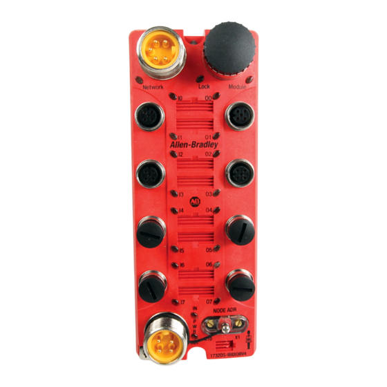
- Page 21 About the Modules 1732DS-IB8 Module Identification Node Address Switches Communication Connector Inputs Power LED Indicators 44123 1732DS-IB8XOBV4 Module Identification Node Address Outputs Switches Communication Connector LED Indicators Inputs I/O Power 44122 Publication 1791DS-UM001H-EN-P - April 2009...
- Page 22 About the Modules 1791DS-IB16 Module Identification Power Connector I/O Connectors (input) LED Indicators LED Indicators T11M T 14 T15M 1791DS- NC NC IB16 NODE 16 INPUTS 24 Vdc 44118 Communication Connector I/O Connectors (input) Node Address Switches Publication 1791DS-UM001H-EN-P - April 2009...
-
Page 23: What This Chapter Contains
Chapter Understand the Operation of Safety Functions What This Chapter Contains Read this chapter for information related to the safety functions of the modules. Also included is a brief overview on international standards and directives that you should be familiar with. Safety I/O Modules The following status is treated as the safety state by the safety I/O modules. -
Page 24: Safety Inputs
Understand the Operation of Safety Functions Configuration Lock After configuration data has been downloaded and verified, the configuration data within the module can be protected either by using RSNetWorx for DeviceNet or RSLogix 5000 software. If the data is protected, the lock indicator on the front panel lights in solid yellow. - Page 25 Understand the Operation of Safety Functions The test output terminal is also used as a power supply to source an external input device to the safety input terminal. Example Use of a 1791DS-IB12 Module Safety 24V dc Output with Test Pulse Input Terminal External Contact...
- Page 26 Understand the Operation of Safety Functions If an error is detected, safety input data and safety input status turn off. Normal Operation and Fault Detection Normal Operation Exte rnal Device Input Terminal 0 Safety Input 0 Remote I/O Data Safety Input Status 0 Fault Detection External Device...
- Page 27 Understand the Operation of Safety Functions Set Dual-channel Mode and Discrepancy Time The consistency between signals on two channels can be evaluated. Either equivalent or complementary can be selected. This function monitors the time during which there is a discrepancy in the logic between the two channels set as dual channels.
- Page 28 Understand the Operation of Safety Functions Dual-channels, Equivalent The status is treated as normal (OK) when both channels are on or off. If one channel is on and the other channel is off, it is treated as a fault (alarm). In the fault (alarm) state, the safety input data and individual safety input status turn off for both inputs.
- Page 29 Understand the Operation of Safety Functions Dual-channels, Complementary The status is treated as normal (OK) when one channel is on and the other channel is off. When both channels are on or both channels are off, it is treated as a fault (alarm). In the fault (alarm) state, safety input 0 is off and safety input 1 is on, and the safety input status turns off for both inputs.
- Page 30 Understand the Operation of Safety Functions Fault Recovery If an error is detected, the safety input data remains in the off state. The procedure for activating the safety input data again is as follows. 1. Remove the cause of the error. 2.
-
Page 31: Safety Outputs
Understand the Operation of Safety Functions Read this section for information about safety outputs. Safety Outputs Safety Output with Test Pulse When the output is on, the test pulse is turned off in a cycle for a period of time as shown in the the table and figure. Using this function, short-circuits between output signal lines and the power supply (positive side) and short-circuits between output signal lines can be detected. - Page 32 Understand the Operation of Safety Functions Dual-channel Setting When the data of both channels is in the on state, and neither channel has an alarm, the outputs are turned on. The status is treated as OK when both channels are OK. If an alarm is detected for one channel, the safety output data and the individual-safety output status turn off for both channels.
-
Page 33: I/O Status Data
Understand the Operation of Safety Functions Fault Recovery If a fault is detected, the safety output remains in the off state. The procedure for activating the safety output data again is as follows. 1. Remove the cause of the error. 2. -
Page 34: Controlling Devices
Understand the Operation of Safety Functions Controlling Devices See the table for sample requirements for controlling devices. Use appropriate devices as indicated in the Controlling ATTENTION Devices - Sample Requirements table. Serious injury may occur due to loss of safety functions. Controlling Devices - Sample Requirements Device Requirement... -
Page 35: Safety Precautions
Understand the Operation of Safety Functions Safety Precautions As serious injury may occur due to loss of required safety function, ATTENTION follow these safety precautions. Do not use test outputs of the modules as safety outputs. Do not use DeviceNet standard I/O data or explicit message data as safety data. - Page 36 Understand the Operation of Safety Functions Europe In Europe, Guard I/O modules are subject to the European Union (EU) Machinery Directive Annex IV, B, Safety Components, items 1 and 2. The type approval of TUV-Rheinland addresses compliance to applicable requirements of the following directives and standards: EU legislation Machinery Directive 98/37/EC Low-voltage Directive 73/23/EEC...
-
Page 37: Ec Directives
DeviceNet products conform to the EMC Directive and Low-voltage Directive. EMC Directive Rockwell Automation devices that comply with EC directives also conform to the related EMC standards so that they can more easily be built into other devices or the overall machine. The actual products have been checked for conformity to EMC standards. - Page 38 Understand the Operation of Safety Functions DeviceNet products that comply with EC directives also conform to the Common Emission Standard (EN 50081-2). Radiated emission characteristics (10-m regulations) may vary depending on the configuration of the control panel used, other devices connected to the control panel, wiring, and other conditions.
-
Page 39: What This Chapter Contains
Chapter Install and Connect Your Modules What This Chapter Contains This chapter explains these general procedures for module use: Install the module in the control panel. Wire I/O power and cables. Connect communication connectors. Set the node address. Configure the system, making settings for the module. The communication baud rate of the entire network is determined by the communication baud rate of the master unit. -
Page 40: Install The Module
Install and Connect Your Modules Install the Module When installing a module follow these instructions. IMPORTANT Use the module in an environment that is within the general specifications. Use the module in an enclosure rated IP54 (IEC60529) or higher. Use DIN rail that is 35 mm (1.38 in.) wide to mount the module in the control panel. -
Page 41: Connect I/O Power And I/O Cables
1791DS-IB8XOBV4 module is shown. 1732DS-IB8XOBV4 module is shown. 1791DS-IB16 modules have identical dimensions. 1732DS-IB8 modules have identical dimensions. Connect I/O Power and I/O See the table for a list of applicable wires that fit the I/O connector when using recommended post-crimp terminals. - Page 42 Install and Connect Your Modules Reference Specifications (Product Specifications of Phoenix Contact) Wire Dimensions Ferrule Specifications Cross- Inner Inner Removed Length of sectional Entire Diameter of Diameter of Ferrule Model Length of Metal Part Area of Length L1 Conductor Insulation Dimensions Insulation Conductor...
-
Page 43: Connect Communication Connectors
Install and Connect Your Modules Use a Phoenix Contact crimping tool (model CRIMPFOX UD6) for the ferrules. When crimping connection cables, follow these IMPORTANT instructions. Use ferrules when wiring cables. Note that I/O connectors are detachable. Tighten the screws on the I/O connector to 0.25…0.3 Nm (2.16…2.59 lb-in). -
Page 44: Set The Node Address
Install and Connect Your Modules Set the Node Address To set the node address, follow these procedures. The node-address setting rotary switches must be set while IMPORTANT the communication power supply is turned off. Sample Node Address Digits Tens Digit Ones Digit 1. -
Page 45: What This Chapter Contains
Chapter Configure Modules in RSLogix 5000 Software What This Chapter Contains This chapter provides information about how to configure your modules in RSLogix 5000 software. Use the Help Button At the bottom of a dialog, click Help for information about how to complete entries on the dialog. - Page 46 Configure Modules in RSLogix 5000 Software You see the Select Module dialog with a list that includes Safety. From the Select Module dialog, click + next to Safety to see a list of modules. 2. From the Select Module dialog, click the + next to Safety to see a list of safety modules.
- Page 47 Configure Modules in RSLogix 5000 Software 3. If desired, from the Select Module dialog that shows the list of modules, click Find, enter text, and click Find Next to find the text in the list of modules. From the Find Text dialog, type text and click Find Next.
-
Page 48: Use The Module Properties And General Dialogs
Configure Modules in RSLogix 5000 Software Use the Module Properties To use the Module Properties and General dialogs to configure a safety module, follow this procedure. and General Dialogs 1. From the I/O configuration tree, double-click the safety module, such as the 1791DS-IB12 module, to see the Module Properties dialog. - Page 49 Configure Modules in RSLogix 5000 Software For example, assume there are two identical GuardLogix control systems - system A and system B - that are connected to a common Ethernet network. Each GuardLogix control system has three DeviceNet networks with assorted standard and safety I/O modules.
- Page 50 Configure Modules in RSLogix 5000 Software Input Data Options Choose from these options: Safety - Selecting Safety creates these tags for the target module: – RunMode: Module mode – ConnectionFaulted: Communications status – Safety Data: Safety inputs from module Safety-Readback - This selection is not available for input-only safety modules.
- Page 51 Configure Modules in RSLogix 5000 Software Input Status Options Choose from these options: Status data is not SIL 3 data. Do not use status data to directly IMPORTANT control a SIL 3 safety output. None - No status tags, only data for the inputs Point Status - One status tag for each input and output point Point Status-Muting - A muting status tag for test output T3 with point status for each input and output point...
- Page 52 Configure Modules in RSLogix 5000 Software Combined Status-Muting – A single BOOL tag represents an AND of the status bits for all the input points. For example, if any input channel has a fault, this bit goes LO. – A single BOOL tag represents an AND of the status bits for all the output points.
- Page 53 Configure Modules in RSLogix 5000 Software Output Data Options Choose from these options. The standard outputs on the module must not be used for safety IMPORTANT purposes. None - Selecting None results in a Listen-only connection to the module. Inputs and status are read, but no outputs are written. Safety - Selecting Safety creates these safety tags and enables these outputs for use in the safety task.
- Page 54 Configure Modules in RSLogix 5000 Software Values and States of Tags This table shows the values and states of the tags. Data Description Input data Safety Input Data Indicates the ON/OFF status of each input terminal. SAFETY • ON: 1 OFF: 0 Combined Safety Input Status An AND of the status of all input terminals.
-
Page 55: Work With The Safety Dialog
Configure Modules in RSLogix 5000 Software Work with the Safety Read this for information about how to complete entries when you click Safety at the top of the Module Properties dialog. Dialog 1. From the Module Properties dialog, click Safety to see the Safety dialog. - Page 56 Configure Modules in RSLogix 5000 Software A. From the Safety dialog, click Advanced to see the Advanced Connection Reaction Time Limit Configuration dialog. We recommend that you keep the Timeout Multiplier and Network Delay Multiplier at their default values of 2 and 200.
- Page 57 Configure Modules in RSLogix 5000 Software A connection status tag exists for every connection. Connection Faulted If the RPI and CRTL for the network are set appropriately, then this status tag will always remain HI. Monitor all connection status bits to verify that they are not going LO intermittently due to timeouts.
-
Page 58: Work With The Input Configuration Dialog
Configure Modules in RSLogix 5000 Software Work with the Input See the table that shows typical safety input parameters, referring to Chapter 2 for related information. Configuration Dialog Typical Safety Input Parameters Value Description Parameter Name Input Delay Time 0…126 ms (in Filter time is for OFF to ON transition. - Page 59 Configure Modules in RSLogix 5000 Software Follow this procedure to complete entries from the Input Configuration Dialog that you see when, from the top of the Module Properties dialog, you click Input Configuration. 1. For Point Operation, for Type, select one of these and a value for Discrepancy Time if set to Equivalent or Complementary: Single Inputs are treated as single channels.
- Page 60 Configure Modules in RSLogix 5000 Software 2. For Point Mode, select one of these for each point, referring to the Safety Input Parameters table for additional information: Not Used - Safety input channel is disabled Safety Pulse Test - Safety input is configured for pulse test operation Safety - Safety input is used with a safety field device Standard - Safety input has a standard field device wired to it...
-
Page 61: Work With Test Output Configuration Dialog
Configure Modules in RSLogix 5000 Software Work with Test Output Read this for information about how to work with the Test Output Configuration dialog, referring to the table that provides information Configuration Dialog on configuring test outputs. Test Output Parameters Value Description Default... -
Page 62: Work With The Output Configuration Dialog
Configure Modules in RSLogix 5000 Software Work with the Output Read this for a procedure on how to configure safety outputs by using the information in the table and completing the entries referring to the Configuration Dialog figure. Safety Output Parameters Parameter Value Description... - Page 63 Configure Modules in RSLogix 5000 Software Follow this procedure to complete entries from the Output Configuration dialog. 1. For Point Operation, select Single or Dual, noting the following if you click Dual: The 1791DS module always sets the high or low as a pair. You must always match the two ouputs as a pair in software as well.
-
Page 64: Save Module Configuration
Configure Modules in RSLogix 5000 Software Save Module Configuration We recommend that after a module is configured you save your work. After downloading the program, if the MS and NS LED indicators on the 1791DS module are not both solid green, this may be due to loss of ownership. -
Page 65: What This Chapter Contains
Chapter Configure Modules in RSNetWorx for DeviceNet Software What This Chapter Contains This chapter provides information about how to configure Guard I/O modules by using RSNetWorx for DeviceNet software and a SmartGuard controller. Refer to the corresponding software help files for network-configurator operating procedures. - Page 66 Configure Modules in RSNetWorx for DeviceNet Software 3. Attach a USB cable between the SmartGuard 600 controller and your computer. The Found New Hardware Wizard dialog appears. 4. From the Found New Hardware Wizard dialog, click Yes, this time only and Next. Publication 1791DS-UM001H-EN-P - April 2009...
- Page 67 Configure Modules in RSNetWorx for DeviceNet Software 5. From the Found New Hardware Wizard dialog that appears, click Install from a list or specific location (Advanced) and Next. 6. From the Found New Hardware Wizard dialog that appears, click Browse. Publication 1791DS-UM001H-EN-P - April 2009...
- Page 68 Configure Modules in RSNetWorx for DeviceNet Software 7. From the Browse For Folder dialog, browse to the folder where the SmartGuard USB drivers were placed. 8. From the Browse For Folder dialog, click OK. 9. From the Found New Hardware Wizard, click Next, noting that if loading of the SmartGuard drivers is successful, you see this dialog.
- Page 69 Configure Modules in RSNetWorx for DeviceNet Software 11. Open RSLinx software, version 2.51 or later, and proceed with configuring the SmartGuard USB driver. Configure the SmartGuard USB Driver Use this procedure to configure the SmartGuard USB driver. 1. Open RSLinx software, version 2.51 or later. 2.
- Page 70 Configure Modules in RSNetWorx for DeviceNet Software 4. From the Configure Drivers dialog, click Add New. 5. From the Add New RSLinx Classic Driver dialog, click OK to see the Configure SmartGuard USB Device dialog. 6. From the Configure SmartGuard USB Device dialog, click 1752 SmartGuard USB Port, noting that the MAC address and Baud Rate fill in and the OK button highlights if the SmartGuard controller is connected properly on the USB link.
- Page 71 Configure Modules in RSNetWorx for DeviceNet Software 7. From the Configure SmartGuard USB Device dialog, click OK to see the Configure Drivers dialog, noting that the SmartGuard driver should be running. 8. From the Configure Drivers dialog, click close. 9. Follow the procedure for working with RSNetworx for DeviceNet software.
- Page 72 Configure Modules in RSNetWorx for DeviceNet Software In this case, we have a single 1791DS safety I/O module connected to the SmartGuard. Note that images of the 1791DS module and SmartGuard (1752) controller show up when you previously load the proper EDS files using the EDS Hardware Installation Tool.
- Page 73 Configure Modules in RSNetWorx for DeviceNet Software 2. Open RSNetworx for DeviceNet software, create a new project, and click the Online icon to see the Browse for network dialog. 3. From the Browse for network dialog, click the SmartGuard driver and OK. 4.
- Page 74 Configure Modules in RSNetWorx for DeviceNet Software 5. From the RSNetWorx for DeviceNet message, click OK. Note that RSNetworx for DeviceNet software finds both the SmartGuard and 1791DS module on the DeviceNet network. Notice that the exclamation mark represents an issue with the safety network number of the 1791DS module.
- Page 75 Configure Modules in RSNetWorx for DeviceNet Software 6. Click the online icon again to put RSNetworx for DeviceNet software in Offline mode. 7. From the RSNetworx for DeviceNet dialog, right-click the SmartGuard icon, select Properties, and follow the procedure for setting up the SmartGuard controller.
- Page 76 Configure Modules in RSNetWorx for DeviceNet Software Set Up the SmartGuard Controller Use this procedure to set up the SmartGuard controller. 1. From the RSNetworx for DeviceNet dialog, right-click SmartGuard and Properties to see the 1752-L24BBB dialog. 2. From the top of the 1752-L24BBB dialog, click Safety Connection to see a dialog that contains a list of all safety I/O modules currently in your project.
- Page 77 Configure Modules in RSNetWorx for DeviceNet Software 3. Right-click the I/O module and select Add Connection to see the Add Safety Connection dialog. Note that individual safety connections for both the inputs and outputs can be added and the SmartGuard 600 controller can have up to 32 connections.
- Page 78 Configure Modules in RSNetWorx for DeviceNet Software Note these input and output connection options: Input connection options Readback is status of 24V on the output terminals. Pt (point) status provides individual status for each input and output point. Combined status is one bit for all inputs, one bit for all safety outputs.
- Page 79 Configure Modules in RSNetWorx for DeviceNet Software 7. From the Add Safety Connection dialog, make selections for the output connection, as shown in the following, and click Add. Note that the connections for a 1791DS- IB8XOB8 module appear as follows, where both connections are 2 bytes. If individual point status was selected, the input connection is 5 bytes.
- Page 80 Configure Modules in RSNetWorx for DeviceNet Software For further details, see the SmartGuard 600 Controllers User Manual, publication 1752-UM001, and SmartGuard 600 Controllers Safety Reference Manual, publication 1752-RM001. 8. From the 1752-L24BBB dialog, click Apply and OK to accept the connection.
- Page 81 Configure Modules in RSNetWorx for DeviceNet Software You see the following nodes after the browse. 10. Right-click the SmartGuard 600 controller, select Download to Device, and follow the download procedure. Publication 1791DS-UM001H-EN-P - April 2009...
- Page 82 Configure Modules in RSNetWorx for DeviceNet Software Download to the SmartGuard 600 Controller Use this procedure to download. 1. Right-click the SmartGuard 600 icon and select Download to Device. 2. From the RSNetWorx for DeviceNet dialog that appears, click Yes. Publication 1791DS-UM001H-EN-P - April 2009...
- Page 83 Configure Modules in RSNetWorx for DeviceNet Software Notice that this dialog appears during the download to the SmartGuard 600. If the download is successful, text appears in the message area, as shown in the following dialog. Publication 1791DS-UM001H-EN-P - April 2009...
- Page 84 Configure Modules in RSNetWorx for DeviceNet Software 3. Right-click the 1791DS module and select Reset Safety Device. 4. From the Reset Safety Device dialog, add a checkmark for Safety Network Number and click Reset, noting that Configuration Owner and Output Connection Owner(s) are already checked. Publication 1791DS-UM001H-EN-P - April 2009...
- Page 85 Configure Modules in RSNetWorx for DeviceNet Software If successfully reset, the following text appears in the message area. Note the exclamation point has changed to a minus sign on the 1791DS module. The minus sign typically means the node is missing; but this is not the case. Disregard the minus sign and continue.
- Page 86 Configure Modules in RSNetWorx for DeviceNet Software 6. From the Safety Network Number dialog, click Download to download the safety network number from the offline project to the 1791DS module. 7. Verify that the NS LED indicator on the 1791DS module is flashing red/green and from the Confirm Safety Network Number dialog, click OK.
- Page 87 Configure Modules in RSNetWorx for DeviceNet Software 9. From the RsNetworx for DeviceNet dialog, click OK to see the Upload or Download Device dialog. 10. From the Upload or Download Device dialog, click Download to download the configuration from RSNetworx for DeviceNet software to the 1791DS module.
- Page 88 Configure Modules in RSNetWorx for DeviceNet Software 11. After the download, from the dialog that appears, click OK. Publication 1791DS-UM001H-EN-P - April 2009...
-
Page 89: What This Chapter Contains
Chapter Wiring Examples What This Chapter Contains Read this chapter for information about wiring and safety categories. See the tables that show input device connection methods and their safety categories. Connected Device and Safety Category Connected Test Output Connection Schematic Diagram Safety Device Configured... - Page 90 Wiring Examples Connected Device and Safety Category Connected Test Output Connection Schematic Diagram Safety Device Configured Category For Pulse Test Emergency stop Connect the switch switches between IN0 and T0, and Door monitor IN1 and T1. 44101 Connect the switches between T0 and IN0, IN1, noting that T0 is configured for 24V...
-
Page 91: Examples Of Wiring
Wiring Examples Examples of Wiring Read this section for examples of wiring by application. 1791DS-IB12 Emergency Stop Switch Dual-channel Inputs with Manual Reset E1: 24V dc Power Supply S1: Emergency Stop Switch (Positive Opening Mechanism) S2: Reset Switch 44104 1791DS-IB12 Emergency Stop Switch Dual-channel Inputs with Manual Reset Controller Configuration Parameter Name Value... - Page 92 Wiring Examples 1791DS-IB12 Two-hand Input E1: 24V dc Power Source S11, S12: Two-hand Switches 31803-M 1791DS-IB12 Two-hand Input Controller Configuration Parameter Name Value Safety Input 0 Safety Input 0 Channel Mode Test Pulse from Test Output Safety Input 0 Test Source Test Output 0 Dual-channel Safety Input 0/1 Mode Dual-channel Complementary...
- Page 93 Wiring Examples 1791DS-IB12 User-mode Switch Input 44132 1791DS-IB12 User-mode Switch Input Controller Configuration Parameter Name Value Safety Input 0 Safety Input 0 Channel Mode Safety Input Safety Input 0 Test Source None Dual-channel Safety Input 0/1 Mode Single Channel Safety Input 1 Safety Input 1 Channel Mode Safety Input Safety Input 1 Test Source...
- Page 94 Wiring Examples 1791DS-12 Muting Lamp Output E1: 24V dc Power Source L1: External Muting Lamp This example shows wiring and configuration when using the 1791DS-IB 12 module. 44107 1791DS-12 Muting Lamp Output Controller Configuration Parameter Name Value Test Output 3 Test Output 3 Mode Muting Lamp Output 1791DS-IB12 Limit Switch Dual-channel Inputs and a Manual Reset...
- Page 95 Wiring Examples 1791DS-IB8XOB8 Solid State Outputs for Dual-channel Mode E1: 24V dc Power Source L1, L2: Loads 44109 1791DS-IB8XOB8 Solid State Outputs for Dual-channel Mode Controller Parameter Name Value Configuration Safety Output 0 Safety Output 0 Channel Mode Safety Pulse Test Dual-channel Safety Output 0/1 Dual-channel Mode...
- Page 96 Wiring Examples 1791DS-IB4XOW4 Relay Outputs with Dual-channel Mode and EDM Input AC Supply E1, E2: 24V dc Power Source KM1, KM2: Magnetic Contactors M: Three-phase Motor F1, F2: Fuses 44110 1791DS-IB4XOW4 Relay Outputs with Dual-channel Mode and EDM Input Controller Parameter Name Value Configuration...
- Page 97 Wiring Examples 1791DS-IB8XOBV4 Dual Safety Inputs User 24V dc 44124 1791DS-IB8XOBV4 Dual Safety Inputs Controller Configuration Parameter Name Value Safety Input 0 Safety Input 0 Channel Mode Test Pulse from Test Output Safety Input 0 Test Source Test Output 0 Dual-channel Safety Input 0/1 Mode Dual-channel Equivalent Dual-channel Safety Input 0/1 Discrepancy Time...
- Page 98 Wiring Examples 1791DS-IB8XOBV4 Standard Inputs and Outputs User 24V dc 44125 1791DS-IB8XOBV4 Standard Inputs and Outputs Controller Configuration Parameter Name Value Input 0 Safety Input 0 Channel Mode Standard Input Test Pulse 0 Test Output 0 Mode 1 Standard Output The example shows wiring and configuration when using a 1791DS-IB8XOBV4 module.
- Page 99 Wiring Examples 1791DS-IB8XOBV4 Dual-load Bipolar Outputs - Example 1 In order for the bipolar safety outputs to work correctly, you IMPORTANT must connect the devices that are being controlled as shown in this figure. Connection of devices directly to 24V DC, 0V DC, or Ground is strictly prohibited.
- Page 100 Wiring Examples 1791DS-IB8XOBV4 Dual-load Bipolar Outputs - Example 2 In order for the bipolar safety outputs to work correctly, you IMPORTANT must connect the devices that are being controlled as shown in this figure. Connection of devices directly to 24V DC, 0V DC, or Ground is strictly prohibited.
-
Page 101: What This Chapter Contains
Chapter Interpret the LED Indicators What This Chapter Contains This chapter includes an explanation of the meaning of module indicators. 1791DS-IB12, See this section for information on how to interpret these module indicators. 1791DS-IB8XOB8, 1791DS-IB4XOW4 Module • MS/NS indicators - The MS (module status) indicator displays the status of a node on the network. - Page 102 Interpret the LED Indicators MS/NS Indicators State Status Description Recommended Action Normal Operation Safety I/O communication in None - normal status - safety I/O communication and standard Solid Green progress. I/O communication are being performed. Online/Connected Solid Green Standby Standard I/O communication None - normal status - standard I/O communication and/or Flashing Green or message communication in...
- Page 103 Interpret the LED Indicators MS/NS Indicators Indicator State Status Description Recommended Action Solid Green Normal Normal operating status. None - normal operation. Flashing Standby Waiting for safety communication from the safety controller . Wait for module to Green establish communication. Solid Red Fatal Fault Hardware fault.
-
Page 104: 1791Ds-Ib8Xobv4, 1791Ds-Ib16, 1732Ds-Ib8Xobv4
Flashing Red When dual channels are set: a fault occurred in the other channel. Correct fault in other channel. Where n indicates the input/out number. 1791DS-IB8XOBV4, See this section for information on how to interpret module indicators. 1791DS-IB16, 1732DS-IB8XOBV4, 1732DS-IB8 Module LED Indicators 24V dc Input Power Indicator State Status Description... - Page 105 Interpret the LED Indicators Module Status Indicator State Status Description Recommended Action No Power or Autobauding No power is applied to the DeviceNet connector. Apply power to this connector. Solid Green Normal Operation The module is operating normally. None. Solid Red Unrecoverable Fault The module has detected an unrecoverable fault.
- Page 106 Interpret the LED Indicators Safety Input Status Indicator State Status Description Recommended Action Safety Input Off Or Module The safety input is off or the module is being Turn the safety input on or wait for the Being Configured configured. module to be configured.
-
Page 107: What This Chapter Contains
Chapter Maintain Your Modules What This Chapter Contains This chapter includes information about troubleshooting and maintenance. Troubleshoot I/O errors can be read from safety input status, test output status, and safety output status indicators. • Status data when I/O is normal (OK): ON (1) •... - Page 108 Maintain Your Modules Safety Input Error Code (hex) Error Content Probable Cause Recommended Action Configuration invalid The configuration is invalid. Configure the module correctly. External test signal error 1) The power source (positive side) is in contact 1) Check the wiring. with the input signal line.
- Page 109 Maintain Your Modules Test Output Error Code (hex) Error Content Probable Cause Recommended Action Configuration invalid The configuration is invalid. Configure the module correctly. Overload detected 1) Ground fault or short-circuit of an output signal line. 1) Check the wiring. 2) Trouble with the connected device.
-
Page 110: Maintenance
Maintain Your Modules Explicit Message for Reading the Cause of the Safety Output Error Explicit Read/ Function Command Response Message write Service Class Instance Attribute Data Code ID (hex) ID (hex) Size (hex) (hex) (hex) Safety Output Read Reads the cause for 0…08 0: No error Cause of Error... - Page 111 Maintain Your Modules Inspect the Modules Inspect the system periodically to keep it in optimal operating condition. In general, inspect the system once every 6 or 12 months, but inspect more frequently if the system is used in high-temperature, humid, or dusty conditions. Prepare the following equipment before inspecting the system.
- Page 112 • When returning a module for repair, attach a detailed description of the problem and return the module to your Rockwell Automation representative. • If there is a faulty contact, wipe the contact with a clean, lint-free cloth dampened with alcohol.
-
Page 113: What This Appendix Contains
Appendix DeviceNet Explicit Messages What This Appendix This appendix lists DeviceNet explicit messages sent from the master unit to a safety I/O module that you can use to read or write any Contains parameter of a specified safety I/O module. The safety I/O module processes the commands sent from the master and then returns responses. - Page 114 DeviceNet Explicit Messages • Service Code - For normal completions, the service code specified in the command with the leftmost bit turned ON is stored as shown in the following table. Function, Command Service Code, and Response Service Code Function Command Service Code (hex) Response Service Code (hex) Read Data Write Data...
-
Page 115: Explicit Messages
DeviceNet Explicit Messages Explicit Messages Reading General Status Explicit Read/ Function Command (hex) Response Message Write Service Class Instance Attribute Data Size Code General Status Read Read the specified 1 byte Read Slave’s status flags Bit 0: Input power error (8 bits). - Page 116 DeviceNet Explicit Messages Monitoring the Test Output Point Explicit Read/ Function Command (hex) Response (hex) Message Write Service Class Instance Attribute Data Size Code Safety Output Read Reads the cause 01…04 0 = No error Cause of Error 01 : (Fault) the normal flag Configuration invalid...
-
Page 117: What This Appendix Contains
Appendix Probability of Failure on Demand (PFD), Probability of Failure per Hour (PFH), and Mean Time Between (MTBF) Data What This Appendix This appendix lists calculated values for probability of failure on demand, probability of failure per hour, and mean time between Contains failure. - Page 118 Probability of Failure on Demand (PFD), Probability of Failure per Hour (PFH), and Mean Time Between (MTBF) Data Calculated Values for Probability of Failure per Hour (PFH) - 1791DS-IB12, 1791DS-IB8XOB8, 1791DS-IB4XOW4 Proof Test Interval 1791DS-IB12 1791DS-IB8XOB8 1791DS-IB4XOW4 Year Hour 0.25 2190 2.009E-10 2.019E-10...
-
Page 119: What This Appendix Contains
Appendix List of Functions What This Appendix This appendix lists functions for the safety I/O modules including safety inputs, test outputs, and safety outputs. Contains List of Functions Safety I/O Modules Item Description Self-diagnosis Function Self-diagnosis is performed when power is turned ON and periodically during operation. When an error occurs, it is treated as a fatal error, the MS indicator lights in red, and all safety output and output data to the network turn OFF. - Page 120 2 (poll, bit-strobe, change of state and cyclic) Allocation Patterns of 1791DS-IB12, For remote I/O communication, you can select and allocate the following I/O data: Remote I/O 1732DS-IB8 • Safety Input Data Communication Module • Individual Safety Input Status • Combined Safety Input Status •...
- Page 121 List of Functions Safety Inputs Item Description Input Channel Mode Any of the following modes can be selected according to the external input device for each input. • Not used - An external input device is not connected. • Safety pulse test - Used with a contact output device in combination with a test output. Using this setting, short circuits between input signal lines and the power supply (positive side) and short circuits between input signal lines can be detected.
- Page 122 List of Functions Test Outputs Item Description Any of the following modes can be selected to accomodate the connected external device. Test Output Mode Not used - An external device is not connected. Standard output - The output is connected to a standard device. Pulse test output - A contact output device is connected and used in combination with a safety input.
-
Page 123: What This Appendix Contains
Appendix Configuration Reference Information What This Appendix This appendix provides information about configuration settings. Contains Understand Parameter The modules have these parameter groups: general parameters, safety input, test output, and safety output. Groups See the tables for the settings in each parameter group. All parameters are set by using RSLogix 5000 or RSNetWorx for DeviceNet software. - Page 124 Configuration Reference Information Safety Input Parameters Parameter Name Value Description Input Delay Time 0…126 ms (in Filter time for OFF to ON transition. Off -> On increments of 6 ms) Input Delay Time 0…126 ms (in Filter time for ON to OFF transition. On ->...
-
Page 125: Allocate Remote I/O
Configuration Reference Information Safety Output Parameters Parameter Name Value Description Default Output Point Mode Not Used An external output devices is not connected. Not Used Safety When the output is ON, the test pulse is not output (remains ON). Safety Pulse Test Using this function, short-circuits between output signal lines and the power supply (positive side) and short-circuits between output signal lines can be detected. - Page 126 Configuration Reference Information Data and Description Data Description Input data Safety Input Data Indicates the ON/OFF status of each input terminal. SAFETY • ON: 1 • OFF: 0 Combined Safety Input Status An AND of the status of all input terminals. SAFETY •...
-
Page 127: I/O Data Supported By Each Module
Configuration Reference Information I/O Data Supported by Each See the tables that show the I/O data supported by each module. Refer to I/O Assembly Data for data arrangements. Module For I/O data, safety connections for up to four items, including one output, can be allocated for the master unit, and standard connections for up to two items can be allocated for the master unit (scanner). - Page 128 Configuration Reference Information 1791DS-IB12 Modules Inputs Outputs Configuration Software Setting (See Module Definition • • Safety • • • Small Safety - Point Status • • • • Safety - Point Status • • • • Safety - Combined Status - Muting Status 310 •...
- Page 129 Configuration Reference Information 1791DS-IB8XOB8 Modules Inputs Outputs Configuration Software Setting (See Module Definition • • Safety • • • Safety - Combined Status - Muting • • • • Status • • Safety - Point Status - Muting • • •...
- Page 130 Configuration Reference Information 1791DS-IB4XOW4 Modules Inputs Outputs Configuration Software Setting (see Module Definition • • Safety • • • Safety - Combined Status - Muting • • • • Status • • Safety - Point Status - Muting • • •...
- Page 131 Configuration Reference Information 1791DS-IB8XOBV4 Modules Inputs Outputs Configuration Software Setting (see Module Definition • • Safety • • • Safety - Combined Status - Muting 324 • • • • • • Safety - Point Status - Muting • • •...
- Page 132 Configuration Reference Information 1732DS-IB8 Modules Inputs Outputs Configuration Software Setting (see Module Definition • • Safety • • • Safety - Point Status - Muting • • • • Status • • Safety - Point Status - Muting - •...
- Page 133 Configuration Reference Information 1732DS-IB8XOBV4 Modules Inputs Outputs Configuration Software Setting (see Module Definition • • Safety • Safety - Combined Status - Muting 324 • • • • • • Safety - Point Status - Muting • • • • •...
- Page 134 Configuration Reference Information 1791DS-IB16 Modules Inputs Outputs Configuration Software Setting (see Module Definition • • Safety • • • Safety - Point Status - Muting • • • • • Safety - Point Status - Muting - • • • •...
-
Page 135: I/O Assembly And Reference Data
Configuration Reference Information I/O Assembly and See the tables for I/O assembly and reference data. Reference Data 1791DS-IB12, 1791DS-IB8XOB8, 1791DS-IB4XOW4 Data The bits in the tag definitions of RSLogix 5000 and RSNetWorx for DeviceNet software are different than those shown in the following section. - Page 136 Configuration Reference Information See these tables for reference data concerning input and output data. Input Data (Catalog Numbers 1791DS-IB12, 1791DS-IB8XOB8, 1791DS-IB4XOW4) Catalog Number Instance Byte Bit 7 Bit 6 Bit 5 Bit 4 Bit 3 Bit 2 Bit 1 Bit 0 (hex) 1791DS-IB4XOW4 203 Reserved...
- Page 137 Configuration Reference Information Input Data (Catalog Numbers 1791DS-IB12, 1791DS-IB8XOB8, 1791DS-IB4XOW4) Catalog Number Instance Byte Bit 7 Bit 6 Bit 5 Bit 4 Bit 3 Bit 2 Bit 1 Bit 0 (hex) 1791DS-IB12 Safety Safety Safety Safety Safety Safety Safety Safety Input 7 Input 6 Input 5...
- Page 138 Configuration Reference Information Input Data (Catalog Numbers 1791DS-IB12, 1791DS-IB8XOB8, 1791DS-IB4XOW4) Catalog Number Instance Byte Bit 7 Bit 6 Bit 5 Bit 4 Bit 3 Bit 2 Bit 1 Bit 0 (hex) 1791DS-IB8XOB8 323 Safety Safety Safety Safety Safety Safety Safety Safety Input 7 Input 6...
- Page 139 Configuration Reference Information Input Data (Catalog Numbers 1791DS-IB12, 1791DS-IB8XOB8, 1791DS-IB4XOW4) Catalog Number Instance Byte Bit 7 Bit 6 Bit 5 Bit 4 Bit 3 Bit 2 Bit 1 Bit 0 (hex) 1791DS-IB8XOB8 341 Reserved Safety Safety Safety Safety Safety Safety Output Input Output 7...
- Page 140 Configuration Reference Information 1732DS-IB8, 1732DS-IB8XOBV4, 1791DS-IB8XOBV4, and 1791DS-IB16 Data The bits in the tag definitions of RSLogix 5000 and RSNetWorx software are different than those shown in the following section. The following table defines the name associations for consistency with the programming software.
- Page 141 Configuration Reference Information Input Data (Catalog Numbers 1732DS-IB8, 1732DS-IB8XOBV4, 1791DS-IB8XOBV4, 1791DS-IB16) Catalog Number Instance Byte Bit 7 Bit 6 Bit 5 Bit 4 Bit 3 Bit 2 Bit 1 Bit 0 (hex) 1732DS-IB8, Safety Safety Safety Safety Safety Safety Safety...
- Page 142 Configuration Reference Information Input Data (Catalog Numbers 1732DS-IB8, 1732DS-IB8XOBV4, 1791DS-IB8XOBV4, 1791DS-IB16) Catalog Number Instance Byte Bit 7 Bit 6 Bit 5 Bit 4 Bit 3 Bit 2 Bit 1 Bit 0 (hex) 1732DS-IB8, Safety Safety Safety Safety Safety Safety Safety...
- Page 143 Configuration Reference Information Input Data (Catalog Numbers 1732DS-IB8, 1732DS-IB8XOBV4, 1791DS-IB8XOBV4, 1791DS-IB16) Catalog Number Instance Byte Bit 7 Bit 6 Bit 5 Bit 4 Bit 3 Bit 2 Bit 1 Bit 0 (hex) 1732DS-IB8, Safety Safety Safety Safety Safety Safety Safety...
- Page 144 Configuration Reference Information Input Data (Catalog Numbers 1732DS-IB8, 1732DS-IB8XOBV4, 1791DS-IB8XOBV4, 1791DS-IB16) Catalog Number Instance Byte Bit 7 Bit 6 Bit 5 Bit 4 Bit 3 Bit 2 Bit 1 Bit 0 (hex) 1732DS-IB8 Reserved Input Power Error Test Test Test...
-
Page 145: What This Appendix Contains
Appendix Get Point Status from Safety I/O Modules by Using Explicit Messaging What This Appendix This appendix provides information about how to use explicit messaging to get point status information from safety I/O modules. Contains One of the variables in maximizing throughput when using DeviceNet safety I/O modules is the size of the I/O assembly, with the other variables being the requested packet interval and baud rate. - Page 146 Get Point Status from Safety I/O Modules by Using Explicit Messaging This creates a two-byte input assembly, as shown for a module called IB8XOB8. 2. Use the combined InputStatus and combined OutputStatus bits to detect if one or more of the I/O points on the module have a fault.
- Page 147 Get Point Status from Safety I/O Modules by Using Explicit Messaging See the figure that shows 1791DS-IB8XOB8 message instruction parameters. Note that we created a UDT for the destination type. • You can find the UDT called Assembly803_1791DS_IB8XOB8 in an ACD file. This UDT is based on the Assembly803 for 1791DS_IB8XOB8 module.
- Page 148 Get Point Status from Safety I/O Modules by Using Explicit Messaging See the figure that shows 1791DS-IBXOB8 Assembly803 UDT. Publication 1791DS-UM001H-EN-P - April 2009...
-
Page 149: Work With 1791Ds-Ib4Xow4 Modules
Get Point Status from Safety I/O Modules by Using Explicit Messaging Work with To work with 1791DS-IB4XOW4 modules, follow this procedure. 1791DS-IB4XOW4 Modules 1. From the Module Definition dialog, use Combined Status-Muting for the Input Status. This creates a one-byte assembly, as shown in the figure, for a module called IB4XOW4. - Page 150 Get Point Status from Safety I/O Modules by Using Explicit Messaging • Note that the second rung can be used to read the status on mode transition and once a fault is detected, continue reading until the fault is corrected. See the figure that shows 1791DS-IB4XXOW4 message instruction parameters.
- Page 151 Get Point Status from Safety I/O Modules by Using Explicit Messaging See the figure that shows 1791DS-IB4XOW4 Assembly819 UDT. Publication 1791DS-UM001H-EN-P - April 2009...
-
Page 152: Work With 1791Ds-Ib12 Modules
Get Point Status from Safety I/O Modules by Using Explicit Messaging Work with 1791DS-IB12 To work with 1791DS-IB12 modules, follow this procedure. Modules 1. From the Module Definition dialog, use Combined Status-Muting for the Input Status. This creates a two-byte input assembly, as shown in the figure, for a module called IB12. - Page 153 Get Point Status from Safety I/O Modules by Using Explicit Messaging • Note that you can use the second rung to read the status on mode transition and once a fault is detected, continue reading until the fault is corrected. See the figure that shows 1791DS-IB12 message instruction parameters.
- Page 154 Get Point Status from Safety I/O Modules by Using Explicit Messaging See the figure that shows the 1791DS-IB12 Assembly786 UDT. Publication 1791DS-UM001H-EN-P - April 2009...
-
Page 155: What This Appendix Contains
Appendix Create SmartGuard 600 Code: An Example What This Appendix This appendix provides sample SmartGuard application code. Read this appendix for information about how to create SmartGuard 600 Contains code on a 1791DS-IB8XOB8 module. This code monitors a light curtain and emergency stop button to control dual safety contactors with feedback, per the following table. - Page 156 Create SmartGuard 600 Code: An Example 2. Double-click the SmartGuard controller to bring up the 1752-L24BBB dialog. Publication 1791DS-UM001H-EN-P - April 2009...
- Page 157 Create SmartGuard 600 Code: An Example 3. From the top of the 1752-L24BBB dialog, click Safety Connection. 4. Verify that you have a project with input and output connections to a 1791DS-IB8XOB8 module, referring to Configure a SmartGuard Controller in this chapter, if needed, to create these connections.
- Page 158 Create SmartGuard 600 Code: An Example 6. Double-click 1791DS module to see its properties dialog. 7. From the top of the dialog, click Safety Configuration. 8. From the dialog, perform this procedure. Publication 1791DS-UM001H-EN-P - April 2009...
- Page 159 Create SmartGuard 600 Code: An Example a. Double-click Input Points 00/01, noting that inputs 00 and 01 are the Estop pushbuttons. Double-click Input Points 00/01 b. Edit the parameters so that the channels are pulse tested by Test sources 0 and 1, respectively. Publication 1791DS-UM001H-EN-P - April 2009...
- Page 160 Create SmartGuard 600 Code: An Example c. Double-click Input Points 00/01 to minimize and Input Points 02/03 to expand, noting the following. • The light curtain is connected to inputs 02 and 03. • The GuardShield pulse tests OSSD1 and OSSD2, so these inputs will be configured as Safety Inputs.
- Page 161 Create SmartGuard 600 Code: An Example d. Double-click Input Points 02/03 to minimize. e. Double-click Input Points 04/05 to expand. f. Add the reset button to input 04, making it a standard input as it is not required to be a safety input. Publication 1791DS-UM001H-EN-P - April 2009...
- Page 162 Create SmartGuard 600 Code: An Example g. Add the AUX feedback circuit for the redundant safety contactors to input 05, making it a safety input as it is not being pulse tested. h. Double-click Input Points 04/05 to minimize. 9. Double-click Output Points 00/01 to expand and follow the procedure to work with output points.
- Page 163 Create SmartGuard 600 Code: An Example Work with Outputs Follow this procedure to work with outputs. 1. Double-click Output Points 00/01 to expand, noting that safety contactors are connected to outputs 00 and 01. Publication 1791DS-UM001H-EN-P - April 2009...
- Page 164 Create SmartGuard 600 Code: An Example 2. Configure them as Safety Pulse test. 3. Double-click Test Output Points to verify that Test outputs 00 and 01 are configured as test sources to support the EStop pulse testing. Publication 1791DS-UM001H-EN-P - April 2009...
- Page 165 Create SmartGuard 600 Code: An Example 4. Click Apply and OK to return to the main RSNetWorx for DeviceNet dialog. 5. Double-click the SmartGuard 600 icon. Publication 1791DS-UM001H-EN-P - April 2009...
- Page 166 Create SmartGuard 600 Code: An Example 6. From the top of the dialog, click Logic. 7. Click Edit to see the SmartGuard editor. 8. Drag over the EStop block and follow the procedure for working with the SmartGuard editor. Publication 1791DS-UM001H-EN-P - April 2009...
- Page 167 Create SmartGuard 600 Code: An Example Work with the SmartGuard Editor Use this procedure as an example of how to work with the SmartGuard editor. 1. Drag over the Estop block . 2. Click the Estop block, hold, and drag and drop onto the dialog. 3.
- Page 168 Create SmartGuard 600 Code: An Example 5. Expand the 1791DS-IB8XOB8 module. 6. Expand the Safety Input dialog. 7. Do the same for the outputs, noting the following: • Inputs are Pt0xData_C01. • Outputs are Pt0xData_C02. • C01 stands for safety connection 1. •...
- Page 169 Create SmartGuard 600 Code: An Example 8. Recall when the safety connections were added to the SmartGuard controller, noticing the following: • Input connection ID is 1. • Output connection ID is 2. Input connection ID is 1. Output connection ID is 2. •...
- Page 170 Create SmartGuard 600 Code: An Example a. Click Edit and Create Comment. b. Click the editor dialog, hold, and drag to outline the comment box. Publication 1791DS-UM001H-EN-P - April 2009...
- Page 171 Create SmartGuard 600 Code: An Example c. Double-click on the comment box. d. Enter the comment text. e. Click OK and click the dialog. 10. Connect the inputs to the Estop block. Publication 1791DS-UM001H-EN-P - April 2009...
- Page 172 Create SmartGuard 600 Code: An Example a. Click on the input red blocks, drag, hold, and drop onto Estop block. b. Click Function Block and drag a Light Curtain Mounitoring block onto the dialog. Publication 1791DS-UM001H-EN-P - April 2009...
- Page 173 Create SmartGuard 600 Code: An Example c. Add the light curtain (LC) input channels and connect them to the block. 11. Add an AND block to the dialog, and connect the outputs of the Estop and LC blocks to its inputs. a.
- Page 174 Create SmartGuard 600 Code: An Example b. Connect the output of the AND to the monitored (lower) input on the Restart. c. Drag the Reset input onto the dialog, and connect it to the restart (top) input of the block. Publication 1791DS-UM001H-EN-P - April 2009...
- Page 175 Create SmartGuard 600 Code: An Example d. Double-click the Restart block. e. From the dialog, click Low-High-Low and Rising Edge. Rising edge uses the Low to High transition. Low-High-Low forces you to release the button, and hold it in for 1 second, approximately. f.
- Page 176 Create SmartGuard 600 Code: An Example 12. Drag the EDM (External Device Monitoring) block onto the dialog. This block controls the dual outputs and monitors for negative feedback. a. Connect the output of the Restart to the Monitored input (lower) of the EDM block. b.
- Page 177 Create SmartGuard 600 Code: An Example c. Connect it to the EDM FEEDBACK input (top) of the EDM block. d. Drag the Contactor Outputs onto the dialog, noting they are on the Output dialog under Safety Output under the 1752-L24BBB module. e.
- Page 178 Create SmartGuard 600 Code: An Example f. Click Apply to see the LogicEditor Tool dialog. g. From the LogicEditor Tool dialog, click OK. 13. Close the editor. Close the editor. 14. From the SmartGuard dialog, click Apply and OK. 15. If online, your program downloads; if offline, you need to download to the SmartGuard controller.
-
Page 179: Putting The Smartguard 600 Into Run Mode
Create SmartGuard 600 Code: An Example Putting the SmartGuard 600 Read this to see how to place the SmartGuard 600 controller into Run mode. into Run Mode 1. From the main RSNetWorx for DeviceNet online node dialog, double-click the SmartGuard 600 icon to see the 1752-L24BBB dialog. - Page 180 Create SmartGuard 600 Code: An Example 3. From the 1752-L24BBB dialog that appears, click Change Mode. 4. From the Change Mode dialog that appears, click Execute and The MS and NS LED indicators on both the SmartGuard 600 and Guard I/O module are now solid green. The SmartGuard 600 controller is now in Run mode and is controlling the Guard I/O module.
-
Page 181: Guard I/O Devicenet Safety Module 1791Ds-Ib8Xobv4
Appendix Specifications Guard I/O DeviceNet Safety Attribute Value Module 1791DS-IB8XOBV4 Safety Input Inputs Type Current sinking Voltage, On-state Input, 11V dc Current, On-State Input, 3.3 mA Voltage, Off-state Input, 5V dc Current, Off-state, Max 1.3 mA IEC 61131-2 (Input Type) Type 3 Pulse Test Output Output Type... - Page 182 Specifications Attribute Value Aggregate Current of 8 A @ 40 °C Outputs per Module 6 A @ 60 °C Pilot Duty Rating 2.5 A inrush Number of Outputs 4 dual channel Includes the presence of a single P stuck-high or M stuck-low short. General Attribute Value...
- Page 183 Specifications Environmental Specifications Attribute Value Temperature, operating IEC 60068-2-1 (Test Ad, Operating Cold), IEC 60068-2-2 (Test Bd, Operating Dry Heat), IEC 60068-2-14 (Test Nb, Operating Thermal Shock): -20…60 °C (-4…140 °F) Temperature, storage IEC 60068-2-1 (Test Ab, Unpackaged Nonoperating Cold), IEC 60068-2-2 (Test Bb, Unpackaged Nonoperating Dry Heat), IEC 60068-2-14 (Test Na, Unpackaged Nonoperating...
- Page 184 Specifications Environmental Specifications Attribute Value Reaction Time Input Reaction Time, Max 16.2 ms + set values of ON/OFF delays Output Reaction Time, Max 6.2 ms + (20 ms) relay response time Signal Sequence Typ. 600 ms Typ. 700 μs 44072 While safety outputs are in an on state, the signal sequence shown in the figure is output continuously for fault diagnosis.
-
Page 185: Guard I/O Devicenet Safety Module 1791Ds-Ib12, 1791Ds-Ib8Xob8, 1791Ds-Ib4Xow4
Specifications Guard I/O DeviceNet Safety I/O Connectors Module 1791DS-IB12, Attribute Value 1791DS-IB8XOB8, Wire type Copper 1791DS-IB4XOW4 Use the following to wire 1791DS. • 0.2…2.5 mm (AWG 24…12) Solid wire • 0.34…1.5 mm (AWG 22…16 ) Standard (flexible) wire with insulation-covered bar terminal Environmental Specifications Attribute... - Page 186 Specifications Safety Input Specifications OFF voltage 5V dc max OFF current 1 mA max Input current 6 mA Test Output Specifications Attribute Value Output type Current sourcing Rated output current 0.7 A Residual voltage 1.2V max Leakage current 0.1 mA max Safety Output Specifications Attribute Value...
- Page 187 Specifications Reaction Time Attribute Value Max input reaction time 16.2 ms + set values of on/off delays Max output reaction time 6.2 ms + (20 ms) relay response time, 1791DS-IB4XOW4 only Certification Value c-UL-us UL Listed Industrial Control Equipment, certified Certifications for US and Canada (all models).
- Page 188 Specifications Notes: Publication 1791DS-UM001H-EN-P - April 2009...
- Page 189 Index ferrite core 34 Found New Hardware Wizard 62 about catalog numbers 13 administrator safety 7 architectures get point status information from safety safety 14 I/O modules 141 bus off 6 help button 41 cable, USB 62 I/O configuration tree 41 cables 37 indicators catalog numbers 13...
- Page 190 Index SmartGuard code example 151 controller 61 See probability of failure on demand. editor 163 See probability of failure per hour. See safety network number. precautions for use 8 standards 32 probability of failure on demand 6 stickers probability of failure per hour 6 on communications connectors 39 publications, related 5 test output configuration dialog 57...
- Page 191 ___No, there is no need to contact me ___Yes, please call me ___Yes, please email me at _______________________ ___Yes, please contact me via _____________________ Return this form to: Rockwell Automation Technical Communications, 1 Allen-Bradley Dr., Mayfield Hts., OH 44124-9705 Fax: 440-646-3525 Email: RADocumentComments@ra.rockwell.com Publication CIG-CO521C-EN-P- May 2003...
- Page 192 PLEASE FASTEN HERE (DO NOT STAPLE) Other Comments PLEASE FOLD HERE NO POSTAGE NECESSARY IF MAILED IN THE UNITED STATES BUSINESS REPLY MAIL FIRST-CLASS MAIL PERMIT NO. 18235 CLEVELAND OH POSTAGE WILL BE PAID BY THE ADDRESSEE 1 ALLEN-BRADLEY DR MAYFIELD HEIGHTS OH 44124-9705...
- Page 196 New Product Satisfaction Return Rockwell Automation tests all of its products to ensure that they are fully operational when shipped from the manufacturing facility. However, if your product is not functioning and needs to be returned, follow these procedures.
Need help?
Do you have a question about the 1732DS-IB8 and is the answer not in the manual?
Questions and answers