
Related Manuals for Rockwell Automation Allen-Bradley 1734-232ASC


Summary of Contents for Rockwell Automation Allen-Bradley 1734-232ASC
- Page 1 POINT I/O ASCII Modules Catalog Numbers 1734-232ASC, 1734-485ASC, 1734-485ASCK User Manual Original Instructions...
- Page 2 If this equipment is used in a manner not specified by the manufacturer, the protection provided by the equipment may be impaired. In no event will Rockwell Automation, Inc. be responsible or liable for indirect or consequential damages resulting from the use or application of this equipment.
-
Page 3: Table Of Contents
Set Up and Use Delimiter Operation......29 Rockwell Automation Publication 1734-UM009C-EN-P - August 2022... - Page 4 ..............41 Rockwell Automation Publication 1734-UM009C-EN-P - August 2022...
-
Page 5: Preface
The purpose of this manual • Related documentation Rockwell Automation recognizes that some of the terms that are currently used in our industry and in this publication are not in alignment with the movement toward inclusive language in technology. We are proactively collaborating with industry peers to find alternatives to such terms and making changes to our products and content. -
Page 6: Additional Resources
POINT I/O Selection Guide, publication 1734-SG001 Provides specifications for the entire POINT I/O family of products. Provides guidance on how to conduct security assessments, implement Rockwell Automation System Security Design Guidelines Reference Manual, publication SECURE-RM001 products in a secure system, harden the control system, manage user access, and dispose of equipment. -
Page 7: General Information On The Ascii Modules
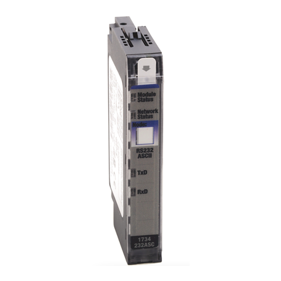
The 1734-232ASC module connects to the RS-232 network while the 1734-485ASC module connects to the RS-485 or RS-422 network. POINT I/O RS-232 and RS-485 ASCII Modules Component Description Description Description Module locking mechanism Interlocking side pieces Rockwell Automation Publication 1734-UM009C-EN-P - August 2022... -
Page 8: Ascii Modules
You can see the data sent from the device in the controller tag. See Read Data from the ASCII Modules into ControlLogix on page The default assembly of the poll response message is shown in Table Rockwell Automation Publication 1734-UM009C-EN-P - August 2022... -
Page 9: Write Serial Output Data To The Ascii Module
Because part of module configuration includes a slot in the POINT I/O system, the owner-controller checks for the presence of a module there. If a module is Rockwell Automation Publication 1734-UM009C-EN-P - August 2022... -
Page 10: Requested Packet Interval
• You inhibit the connection to the module, change the RPI value, and uninhibit the connection. • You change the RPI value. In this case, the connection is closed and reopened immediately after you apply the change to the module configuration. Rockwell Automation Publication 1734-UM009C-EN-P - August 2022... -
Page 11: Listen Only Mode
Number byte value and initiates a new serial port transmission with each message that is received from the controller. Carefully consider when you select this option for I/O messaging. See POINT I/O Parameters on page 25 for details. Rockwell Automation Publication 1734-UM009C-EN-P - August 2022... -
Page 12: Produce Immediate And Master/Slave Handshake Option
You can use module inhibiting in the following ways: • You write a configuration for an I/O module but inhibit the module to help prevent it from communicating with the owner-controller. The Rockwell Automation Publication 1734-UM009C-EN-P - August 2022... -
Page 13: Electronic Keying
The specific type of the product. The Product Code maps to a catalog number. Major Revision A number that represents the functional capabilities of a device. Minor Revision A number that represents behavior changes in the device. Rockwell Automation Publication 1734-UM009C-EN-P - August 2022... - Page 14 Indicates that all keying attributes must match to establish communication. If any attribute does Exact Match not match precisely, communication with the device does not occur. Carefully consider the implications of each keying option when selecting one. Rockwell Automation Publication 1734-UM009C-EN-P - August 2022...
-
Page 15: Configure The Ascii Module
POINT I/O EtherNet/IP adapter to the project, complete these steps to add modules to the project. This example shows how to add a 1734-485ASC module when the Studio 5000 Logix Designer application project is offline. Rockwell Automation Publication 1734-UM009C-EN-P - August 2022... - Page 16 If you cleared the Close on Create checkbox when you created the first I/O module, repeat step 2. • If you did not clear the Close on Create checkbox when you created the first I/O module, repeat steps 1…2. Rockwell Automation Publication 1734-UM009C-EN-P - August 2022...
-
Page 17: Edit The Module Configuration Categories
Module Definition dialog box. IMPORTANT The graphic is an example of a Module Definition dialog box. The same set of fields and options are not available on all POINT I/O modules. Rockwell Automation Publication 1734-UM009C-EN-P - August 2022... -
Page 18: Connection Category
Module Inhibiting on page • Configure whether a connection failure while the controller is in Run mode causes a major or minor fault. • Configure whether to use a Unicast connection over the EtherNet/IP network. Rockwell Automation Publication 1734-UM009C-EN-P - August 2022... -
Page 19: Module Info Category
Refresh the data on the screen • Reset the module Configuration Category The Configuration category lets you complete the following tasks: • Set the Baud rate. For more information about the baud rate, see Parameter List on page Rockwell Automation Publication 1734-UM009C-EN-P - August 2022... -
Page 20: Advance Format Configuration Category
Enable or disable Pad Mode. For more information about pad mode, see Pad and No Pad Option on page • Define the receive pad character. For more information about pad characters, see Pad and No Pad Option on page Rockwell Automation Publication 1734-UM009C-EN-P - August 2022... -
Page 21: View The Module Tags
1. In the Controller Organizer, right-click Controller Tags and choose Monitor Tags. The Controller Tags dialog box appears with data. 2. To view module tags as shown, click the symbols. For more information on module tags, see Module Tag Definitions on page Rockwell Automation Publication 1734-UM009C-EN-P - August 2022... - Page 22 Chapter 2 Configure the ASCII Module Notes: Rockwell Automation Publication 1734-UM009C-EN-P - August 2022...
-
Page 23: Module Tag Definitions
The possible POINT I/O analog module tag types are C (configuration), I (input), and O (output). • Data = tag function In this case, Data represents the input data that is returned to the owner- controller. Rockwell Automation Publication 1734-UM009C-EN-P - August 2022... -
Page 24: Access The Tags
ASCII Receive Record End Mode ASCII Receive End Delimiter ASCII Receive String Data Type ASCII Pad Mode ASCII Pad Character ASCII Receive Swap Mode Ethernet Handshake Mode ASCII Max Number of Transmit Characters Rockwell Automation Publication 1734-UM009C-EN-P - August 2022... -
Page 25: Point I/O Parameters
1 = 16 bit Swap Enabled Receive Swap Mode Get/Set Disabled USINT messages is swapped 2 = 24 bit Swap Enabled every 2, 3, or 4 3 = 32 bit Swap Enabled Rockwell Automation Publication 1734-UM009C-EN-P - August 2022... - Page 26 2 = RX FIFO Overflow Status the receive record object 4 = RX Parity Error No Status USINT and the transmit record 64 = Handshake Error object. 128 = New Data Flag Rockwell Automation Publication 1734-UM009C-EN-P - August 2022...
-
Page 27: Receive Serial Data From The Ascii Device
Pad Mode allows for compatibility with scanners that cannot receive variable length I/O messages. For such scanners, you must turn Pad mode ON (a value of 1). Turning Pad mode ON does not harm Scanners that do support variable length receive messages. Rockwell Automation Publication 1734-UM009C-EN-P - August 2022... -
Page 28: Set Up And Use The Swap Bytes Mode
Maximum Number of Receive Characters Parameter Rules for Usage • Swap Bytes Mode is set for transmit and receive independently. • The byte swapping works best if the max RX and TX lengths are multiples of the byte-swap size. Rockwell Automation Publication 1734-UM009C-EN-P - August 2022... -
Page 29: Set Up And Use Delimiter Operation
Table 10 - Receive Data Format — Short_String Data Type Byte 1 Byte 2 Byte 3 Byte 4 Byte 5-X Byte X+1 (Max = 132) Receive Record Number Status Byte Reserved Length ASCII Data (max 128 bytes) <CR> (Terminator) Rockwell Automation Publication 1734-UM009C-EN-P - August 2022... -
Page 30: Status Byte Description
Transmit Serial Data to the To transmit data to your serial device, the data must first be sent to the ASCII ASCII Device module and then the ASCII module must send the data to the serial device. Rockwell Automation Publication 1734-UM009C-EN-P - August 2022... -
Page 31: Set Up The Transmit Character Buffer Length
Byte 3 Byte 4 Byte 5-X (Max = 132) Next Transmit Record Number ASCII Data End of String Delimiter or Transmit Record Number Reserved Reserved (Handshake Mode Only) (max 128 bytes) Last Data Byte Rockwell Automation Publication 1734-UM009C-EN-P - August 2022... -
Page 32: Transmit Handshake Or Transmit Immediate Mode
In Transmit Immediate Mode, the ASCII module transmits data out of its serial port every time it receives an I/O command or explicit message to its transmit buffer or changes the transmit record number. Rockwell Automation Publication 1734-UM009C-EN-P - August 2022... -
Page 33: Transmit Serial Data
In Master/Slave Handshake mode, the ASCII module refrains from updating the new ASCII data until the master requests it. This technique is useful when the master must ensure that some specific actions take place before receiving the new serial data. Rockwell Automation Publication 1734-UM009C-EN-P - August 2022... - Page 34 Receive Record Number that is sent from the module, if desired, or any other meaningful number. The ASCII module only looks for a change from the value since it set the New Data Flag. Rockwell Automation Publication 1734-UM009C-EN-P - August 2022...
-
Page 35: Interpret Status Indicators
Device online and has connections in the established state. Flashing red One or more I/O connections in timed-out state. Critical link failure - failed communication device. Device detected error that helps prevent it communicating on the network. Rockwell Automation Publication 1734-UM009C-EN-P - August 2022... - Page 36 If it flashes, you are not properly initiating transmission via I/O messaging. If it does flash, check the remote device. Off transmit/green receive Check connections as you may have wired the device backwards. Rockwell Automation Publication 1734-UM009C-EN-P - August 2022...
-
Page 37: About These Examples
Lastly, the Transmit Record Number byte 2 must be changed from its previous value to trigger the transmission (for instance, by incrementing the ID value by 1 each time a message is to be sent). Rockwell Automation Publication 1734-UM009C-EN-P - August 2022... -
Page 38: Receive Data From The Ascii Modules
AENTR_IP85:1:I.ReceiveRecordNumber has changed from a previously stored value. If it has changed, the data starting in AENTR_IP85:1:I.Data[0] is copied to a file and the current receive record number is stored into a data location. Rockwell Automation Publication 1734-UM009C-EN-P - August 2022... -
Page 39: Transmit Data From Controllogix Through The Ascii Modules
Figure 3 - Transmit Record Number Location in Controller Tags Dialog The ladder logic in Figure 4 on page 40 increments a counter every 8 seconds and then copies the accumulator value of the counter into the Transmit Record Rockwell Automation Publication 1734-UM009C-EN-P - August 2022... - Page 40 20 is in AENTR_IP85:1:O.Length. Under normal conditions, the transmit data and length is loaded by the ladder program before incrementing the Transmit Record Number. Figure 5 - Controller Tags Output Table Rockwell Automation Publication 1734-UM009C-EN-P - August 2022...
-
Page 41: Index
23 define pad character 20 command Delimiter operation Poll 12 communication set up 29 Diagnostics 35 communication 8 component description 7 dialog module components Controller Tag 21 module components 7 module definition Rockwell Automation Publication 1734-UM009C-EN-P - August 2022... - Page 42 12 parameter 21 immediate 12 transmit byte swap 28 no pad 12 parameters 18 pad 12 ASCII module 25 set up 27 Parity error record header 32 RX 30 module identification 19 Rockwell Automation Publication 1734-UM009C-EN-P - August 2022...
- Page 43 8 serial port Short_String String 18 configure 20 Transmit Record Number 9 set baud rate TX buffer overflow 30 configuration category 19 set handshake mode 20 Set module parameters 17 Unicast connection 18 Rockwell Automation Publication 1734-UM009C-EN-P - August 2022...
- Page 44 Index variable length receive messages 27 word organization 4-byte 28 Rockwell Automation Publication 1734-UM009C-EN-P - August 2022...
- Page 45 POINT I/O ASCII Modules User Manual Rockwell Automation Publication 1734-UM009C-EN-P - August 2022...
- Page 46 At the end of life, this equipment should be collected separately from any unsorted municipal waste. Rockwell Automation maintains current product environmental information on its website at rok.auto/pec. Allen-Bradley, ArmorPOINT, CompactLogix, ControlLogix, expanding human possibility, FactoryTalk, Logix 5000, POINT I/O, Rockwell Automation, Studio 5000 Logix Designer, and TechConnect are trademarks of Rockwell Automation, Inc.
Need help?
Do you have a question about the Allen-Bradley 1734-232ASC and is the answer not in the manual?
Questions and answers