
Related Manuals for Rockwell Automation Allen-Bradley Guard I/O DeviceNet 1732DS-IB8


Summary of Contents for Rockwell Automation Allen-Bradley Guard I/O DeviceNet 1732DS-IB8
- Page 1 User Manual Guard I/O DeviceNet Safety Modules Catalog Numbers 1732DS-IB8, 1732DS-IB8XOBV4, 1791DS-IB12, 1791DS-IB8XOB8, 1791DS-IB4XOW4, 1791DS-IB8XOBV4, 1791DS-IB16...
- Page 2 IMPORTANT Identifies information that is critical for successful application and understanding of the product. Allen-Bradley, Rockwell Software, Rockwell Automation, GuardLogix, SmartGuard, RSNetWorx, RSLogix, Logix 5000, Studio 5000, Guard I/O, CompactBlock, and TechConnect are trademarks of Rockwell Automation, Inc. Trademarks not belonging to Rockwell Automation are property of their respective companies.
- Page 3 New and Updated This table contains the changes made to this revision. Information Topic Page Studio 5000 Environment Additional Resources Programming Requirements Safety Data Rockwell Automation Publication 1791DS-UM001J-EN-P - May 2013...
- Page 4 Summary of Changes Notes: Rockwell Automation Publication 1791DS-UM001J-EN-P - May 2013...
-
Page 5: Table Of Contents
Compliance with EC Directives ....... 41 Rockwell Automation Publication 1791DS-UM001J-EN-P - May 2013... - Page 6 Configure the Output Configuration Tab ......77 Save and Download Module Configuration......79 Rockwell Automation Publication 1791DS-UM001J-EN-P - May 2013...
- Page 7 I/O Assembly and Reference Data ....... . 148 Rockwell Automation Publication 1791DS-UM001J-EN-P - May 2013...
- Page 8 I/O Data Supported by Each Module ......167 Index Rockwell Automation Publication 1791DS-UM001J-EN-P - May 2013...
-
Page 9: About The Specifications And Dimensions In This Manual
Preface Read and understand this manual before using the described products. Consult your Rockwell Automation representative if you have any questions or comments. This manual describes how to use the Guard I/O modules. This manual is intended for users of ArmorBlock and CompactBlock Guard I/O modules. -
Page 10: Additional Resources
Describes how to configure, operate, and troubleshoot the controller. ODVA Planning and Installation Manual, publication 00027, available from the Describes the required media components and how to plan for and install these required EtherNet/IP Library at ODVA.org components. Rockwell Automation Publication 1791DS-UM001J-EN-P - May 2013... -
Page 11: Terminology
Acronym for safety network number, which uniquely identifies a network across all networks in the safety system. You are responsible for assigning a unique number for each safety network or safety sub-net within a system. Standard Devices or portions of devices that do not participate in the safety function. Rockwell Automation Publication 1791DS-UM001J-EN-P - May 2013... - Page 12 Preface Notes: Rockwell Automation Publication 1791DS-UM001J-EN-P - May 2013...
-
Page 13: Before You Begin
• Verify for CE LVD compliance, the external power supply that provides power to the modules is safety extra-low voltage (SELV) rated. Some Rockwell Automation Bulletin 1606 power supplies are SELV-compliant. Verify this in the Bulletin 1606 Installation Instructions. Verify that the Guard I/O firmware version is correct prior to commissioning the safety system, noting that firmware information related to safety controllers is available at http://www.rockwellautomation.com/products/certification/safety. -
Page 14: Understand Suitability For Use
Never use the products for an application involving serious risk to life or property without making sure that the system as a whole was designed to address the risks and that the Rockwell Automation product is properly rated and installed for the intended use within the overall equipment or system. - Page 15 • Note that you must confirm compliance with the applicable standards for the entire system. • Disconnect the module from the power supply before wiring. Devices connected to the module may operate unexpectedly if wiring is performed while power is supplied. Rockwell Automation Publication 1791DS-UM001J-EN-P - May 2013...
- Page 16 F1, F2, and F3. Figure 1 - Use of Isolating Transformer 1791DS-IB4XOW4 Module 400V AC/ 230V AC L2 L3 F1…F8 - Fuses MA, MB - Electromagnetic Switches TR1 - Insulated Transformer Load Over-voltage Category 44151 Rockwell Automation Publication 1791DS-UM001J-EN-P - May 2013...
-
Page 17: Precautions To Mount, Wire, And Clean
CIP safety over a DeviceNet network. Data processing is performed in the safety controller. The status and fault diagnostics of Guard I/O modules are monitored by a safety controller through a safety connection using a new or existing DeviceNet network. Rockwell Automation Publication 1791DS-UM001J-EN-P - May 2013... - Page 18 • I/O status data - In addition to I/O data, the module includes status data for monitoring I/O circuits. • Security - The configuration information of the module can be protected by a password. • Removable I/O connectors - I/O connectors support mechanical keying. Rockwell Automation Publication 1791DS-UM001J-EN-P - May 2013...
-
Page 19: Programming Requirements
The Guard I/O family is a set of I/O modules that when connected to a Architectures DeviceNet safety network are suitable for applications up to SIL3, as defined in the IEC 61508 standard, and Safety Category 4, as defined in the EN 954-1 standard. Rockwell Automation Publication 1791DS-UM001J-EN-P - May 2013... - Page 20 Studio 5000, and Guard I/O Module RSLogixGuard Plus Software ArmorBlock Guard I/O 44196 Module Safety Communication Standard Communication Safety controllers control the safety outputs. Safety or standard PLC controllers can control the standard outputs. Rockwell Automation Publication 1791DS-UM001J-EN-P - May 2013...
-
Page 21: Identify Major Parts Of The Modules
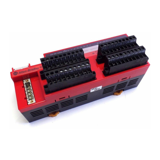
Figure 5 - 1791DS-IB12 Module Identification Status Indicators Node Address Switches 0 1 2 3 4 5 6 7 8 9 10 MS NS LOCK CompactBlock 1791DS-IB12 12 Inputs 24VDC Communication Connector 44091 I/O Connections Rockwell Automation Publication 1791DS-UM001J-EN-P - May 2013... - Page 22 Figure 7 - 1732DS-IB8 Module Identification Node Address Switches Communication Connector 44123 Inputs Power Status Indicators Figure 8 - 1732DS-IB8XOBV4 Module Identification Node Address Outputs Switches Communication Connector 44122 Status Indicators Inputs I/O Power Rockwell Automation Publication 1791DS-UM001J-EN-P - May 2013...
- Page 23 Figure 9 - 1791DS-IB16 Module Identification Power Connector I/O Connectors (input) Status Indicators T11M T 14 T15M 1791DS- NC NC IB16 NODE 16 INPUTS 24 Vdc 44118 Communication Connector I/O Connectors (input) Node Address Switches Rockwell Automation Publication 1791DS-UM001J-EN-P - May 2013...
- Page 24 Chapter 1 About the Modules Notes: Rockwell Automation Publication 1791DS-UM001J-EN-P - May 2013...
-
Page 25: Safety I/O Modules
The following status is the safety state of the Guard I/O modules: • Safety outputs: off • Safety input data to network: off Figure 10 - Safety Status DeviceNet Network Inputs to Network Safety Status Output Off Input 44076 Rockwell Automation Publication 1791DS-UM001J-EN-P - May 2013... -
Page 26: Self-Diagnostic Functions
Safety Inputs Read this section for information about safety inputs and their associated test outputs. A safety input may be used with test outputs. Safety inputs are used to monitor safety input devices. Rockwell Automation Publication 1791DS-UM001J-EN-P - May 2013... -
Page 27: Using A Test Output With A Safety Input
1791DS-IB12 700 μs 648 ms 1791DS-IB8XOB8 700 μs 648 ms 1791DS-IB4XOW4 700 μs 648 ms 1791DS-IB8XOBV4 500 μs 600 ms 1791DS-IB16 500 μs 600 ms Figure 12 - Test Pulse in a Cycle Rockwell Automation Publication 1791DS-UM001J-EN-P - May 2013... - Page 28 Figure 13 - Short-circuit Between Input Signal Lines External Contact Short-circuit Between Input Signal Lines and Power Supply (positive side) External Contact 44079 Short-circuit Between Input Signal Lines Rockwell Automation Publication 1791DS-UM001J-EN-P - May 2013...
-
Page 29: Single Channel Mode
Normal Operation External Device Input Terminal 0 Safety Input 0 Remote Data Safety Input Status 0 Fault Detection External Device Input Terminal 0 Fault Detected Safety Input 0 Remote Data Safety Input Status 0 Rockwell Automation Publication 1791DS-UM001J-EN-P - May 2013... -
Page 30: Dual-Channel Mode And Discrepancy Time
If the second transition does not occur before the discrepancy time elapses, the channels will fault. In the fault state the input and status for both channels are set low (off ). When configured as an Rockwell Automation Publication 1791DS-UM001J-EN-P - May 2013... -
Page 31: Dual-Channels, Complementary
The fault state of complementary inputs is the even- numbered input turned off and the odd-numbered input turned on. Note that if faulted, both channel status bits are set low. When configured as a Rockwell Automation Publication 1791DS-UM001J-EN-P - May 2013... - Page 32 Discrepancy Time Safety Input 0 Remote Safety Input 1 Data Safety Input Status 0, 1 Fault Detection Discrepancy Time Safety Input 0 Remote Safety Input 1 Data Fault Detected Safety Input Status 0, 1 Rockwell Automation Publication 1791DS-UM001J-EN-P - May 2013...
-
Page 33: Safety Input Fault Recovery
This helps prevent rapid changes of the input data due to contact bounce. Figure 18 - Off-delay Input Signal Input Signal Remote I/O Data Safety Input Safety Input Off-delay OFF-delay 44095 Rockwell Automation Publication 1791DS-UM001J-EN-P - May 2013... -
Page 34: Test Outputs Configured As Muting Outputs
LO if the circuit is logically LO: • DCSTM • FSBM • TSAM • TSSM Rockwell Automation Publication 1791DS-UM001J-EN-P - May 2013... - Page 35 In this code, the actual muting status bit is used in the first rung, and the DN bit of the timer is used in the muting status parameter of the instruction. The actual test output data bit is used in both the first and last rungs. Rockwell Automation Publication 1791DS-UM001J-EN-P - May 2013...
-
Page 36: Safety Outputs
Figure 19 - Test Pulse in a Cycle 44096 To prevent the test pulse from causing the connected device to IMPORTANT malfunction, pay careful attention to the input response time of the device. Rockwell Automation Publication 1791DS-UM001J-EN-P - May 2013... -
Page 37: Dual-Channel Setting
2. Place the safety output (or safety outputs) into the safety state. The safety output status turns on (fault cleared) when the output-error latch time has elapsed. The I/O indicator (red) turns off. The output data can now be controlled. Rockwell Automation Publication 1791DS-UM001J-EN-P - May 2013... -
Page 38: Controlling Devices
• When replacing a device, configure the replacement device suitably and confirm that it operates correctly. • When installing or replacing modules, clear any previous configuration before connecting input or output power to the device. Rockwell Automation Publication 1791DS-UM001J-EN-P - May 2013... -
Page 39: Legislation And Standards
• European standards – EN 61508 (SIL1-3) – EN 954-1 (Category 4, 3, 2, 1, B) – EN 61131-2 – EN 418 – EN 60204-1 – IEC 61000-6-2 – IEC 61000-6-4 – IEC 13849 Rockwell Automation Publication 1791DS-UM001J-EN-P - May 2013... -
Page 40: North America
Accordingly, to use the module in Japan as a safety device for press machine or shearing tool pursuant to Article 42 of the above- mentioned law, it is necessary to apply for testing of the entire system. Rockwell Automation Publication 1791DS-UM001J-EN-P - May 2013... -
Page 41: Ec Directives
EMC-related performance of Rockwell Automation devices that comply with EMC directive vary depending on the configuration, wiring, and other conditions of the equipment or control panel in which the Rockwell Automation devices are installed. The customer must, therefore, perform the final check to confirm that devices and the overall machine conform to EMC standards. - Page 42 Wire the control panel with cables that are as short as possible and ground EXAMPLE to 100 Ω or less. Keep DeviceNet communication cables as short as possible and ground to EXAMPLE 100 Ω or less. Rockwell Automation Publication 1791DS-UM001J-EN-P - May 2013...
-
Page 43: Considerations For Module Installation
• Reset modules to their out-of-box condition when removing them from an application. • Be sure that all modules in replacement stock are in their out-of-box condition. Rockwell Automation Publication 1791DS-UM001J-EN-P - May 2013... -
Page 44: Install The Module
You can install modules horizontally or vertically. IMPORTANT Figure 21 - Module Installation (1791DS-IB12, 1791DS-IB8XOB8, and 1791DS-IB4XOW4 modules) 35 (1.38) Dimensions are in mm (in.). End Plate 50 (1.96) 50 (1.96) End Plate Rockwell Automation Publication 1791DS-UM001J-EN-P - May 2013... -
Page 45: Connect I/O Power And I/O Cables
• When present, do not remove debris shield from the module before wiring. • When present, always remove the debris shield after completing wiring to be sure of proper heat dispersion. Rockwell Automation Publication 1791DS-UM001J-EN-P - May 2013... -
Page 46: Connect Communication Connectors
2. Use the left rotary switch to set the tens digit of node address (decimal). 3. Use the right rotary switch to set the ones digit. If the node address switches are set from 64…99, the node address needs to be set from RSNetWorx for DeviceNet software. Rockwell Automation Publication 1791DS-UM001J-EN-P - May 2013... -
Page 47: Input Examples
Systems CD, publication SAFETY-CL002, or download toolkit files from the Integrated Architecture Tools and Resources website at http://www.ab.com/go/iatools. Read this section for input examples by application. For details, refer to the Input Examples installation instructions for each catalog number. Rockwell Automation Publication 1791DS-UM001J-EN-P - May 2013... -
Page 48: Emergency Stop Switch Dual-Channel Inputs With Manual Reset
Dual-channel Safety Input 2/3 Mode Single Channel Test Output 0 Test Output 0 Mode Pulse Test Output Test Output 1 Test Output 1 Mode Pulse Test Output Test Output 2 Test Output 2 Mode Power Supply Output Rockwell Automation Publication 1791DS-UM001J-EN-P - May 2013... -
Page 49: Two-Hand Monitor
Test Pulse from Test Output Safety Input 3 Test Source Test Output 1 Test Output 0 Test Output 0 Mode Pulse Test Output Test Output 1 Test Output 1 Mode Pulse Test Output Rockwell Automation Publication 1791DS-UM001J-EN-P - May 2013... -
Page 50: Mode Select Switch
Safety Input 6 Channel Mode Safety Input Safety Input 6 Test Source None Dual-channel Safety Input 6/7 Mode Single Channel Safety Input 7 Safety Input 7 Channel Mode Safety Input Safety Input 7 Test Source None Rockwell Automation Publication 1791DS-UM001J-EN-P - May 2013... -
Page 51: Light Curtain
None Dual-channel Safety Input 0/1 Mode Dual-channel Equivalent Dual-channel Safety Input 0/1 Discrepancy Time 100 ms (application dependent) Safety Input 1 Safety Input 1 Channel Mode Safety Safety Input 1 Test Source None Rockwell Automation Publication 1791DS-UM001J-EN-P - May 2013... -
Page 52: Reset Switch
Connect the switch between 24V DC and I0. 31820-M Controller Parameter Name Configuration Setting Configuration Safety Input 0 Safety Input 0 Channel Mode Standard Safety Input 0 Test Source None Dual-channel Safety Input 0/1 Mode Single channel Rockwell Automation Publication 1791DS-UM001J-EN-P - May 2013... -
Page 53: Source Output Examples
Test Output 0 Mode Pulse Test Output Safety Output 0 Safety Output 0 Channel Mode Safety Pulse Test Dual-channel Safety Output 0/1 Mode Dual-channel Safety Output 1 Safety Output 1 Channel Mode Safety Pulse Test Rockwell Automation Publication 1791DS-UM001J-EN-P - May 2013... -
Page 54: Single Channel
If used in combination with the programs in a safety controller, this wiring is Safety Category 4 in accordance with EN 954-1 wiring requirements. OUT 0 V0, G0: Input Power Connection 31821-M V1, G1: Output Power Connection M: Three-phase Motor Rockwell Automation Publication 1791DS-UM001J-EN-P - May 2013... -
Page 55: Bipolar Output Examples
Single Channel Test Output 0 Test Output 0 Mode Pulse Test Output Safety Output 0 Safety Output 0 Channel Mode Safety Pulse Test Safety Output 1 Safety Output 1 Channel Mode Safety Pulse Test Rockwell Automation Publication 1791DS-UM001J-EN-P - May 2013... -
Page 56: Single Channel
OU T- PS1, PS2: User 24V DC power supply. (A single E1, E2: 24V DC Power Source 31822-M power supply can be used for both input and K1: Contactor output power.) M: Three-phase Motor Rockwell Automation Publication 1791DS-UM001J-EN-P - May 2013... -
Page 57: Relay Output Examples
Test Output 0 Test Output 0 Mode Pulse Test Output Safety Output 0 Safety Output 0 Channel Mode Safety Dual-channel Safety Output 0/1 Mode Dual-channel Safety Output 1 Safety Output 1 Channel Mode Safety Rockwell Automation Publication 1791DS-UM001J-EN-P - May 2013... -
Page 58: Interlock String
If used in combination with the programs in a safety controller, this wiring is Safety Category 4 in accordance with EN 954-1 wiring requirements. OUT 0 Robot OUT 1 31823-M Rockwell Automation Publication 1791DS-UM001J-EN-P - May 2013... -
Page 59: Test Output Examples
Safety Input 1 Safety Input 1 Channel Mode Standard Input Safety Input 1 Test Source None Dual-channel Safety Input 0/1 Mode Single Channel Test Pulse 0 Test Output 0 Mode 1 Standard Output Rockwell Automation Publication 1791DS-UM001J-EN-P - May 2013... -
Page 60: Muting Lamp Output
This example shows wiring and controller configuration when using a Guard I/O module with a muting lamp output. PS1: User 24V DC Power Supply 31810-M Controller Parameter Name Configuration Setting Configuration Test Output 3 Test Output 3 Mode Muting Lamp Output Rockwell Automation Publication 1791DS-UM001J-EN-P - May 2013... -
Page 61: Use The Help Button
At the bottom of a dialog box, click Help for information about how to complete entries in the dialog box. At the bottom of a warning dialog box, click Help to get information about that specific error. Rockwell Automation Publication 1791DS-UM001J-EN-P - May 2013... -
Page 62: Add Modules To The I/O Configuration Tree
1. From the I/O Configuration tree, right-click the 1756-DNB module and choose New Module. The Select Module dialog box appears with a list that includes Safety. 2. Expand the Safety category, select the appropriate module, and click OK. Rockwell Automation Publication 1791DS-UM001J-EN-P - May 2013... - Page 63 We suggest that all safety modules on a network have the same SNN, to make documentation easier. During configuration, the Logix Designer application defaults a safety device’s SNN to match the SNN of the lowest safety node on the network. Rockwell Automation Publication 1791DS-UM001J-EN-P - May 2013...
-
Page 64: Set Up The Module Definition
All of the parameters must match or the inserted module rejects a connection to the controller. Compatible Module Allows an I/O module to determine whether it can emulate the module defined in the configuration sent from the controller. Rockwell Automation Publication 1791DS-UM001J-EN-P - May 2013... - Page 65 Chapter 5 5. Assign the input data. Choose Description Safety These tags are created for the target module: ·RunMode for module mode ·ConnectionFaulted for communication status ·Safety Data for safety inputs from the module Rockwell Automation Publication 1791DS-UM001J-EN-P - May 2013...
- Page 66 The Small Safety option reduces the amount of data that the 12-point module sends to the controller to improve network performance. Safety data and point status tags are created. Point status is diagnostic status for each of the eight input points. Rockwell Automation Publication 1791DS-UM001J-EN-P - May 2013...
- Page 67 There is one status tag for each input and output point. Pt. Status - Muting There is a muting status tag for test output T3, T7, T11, and T15 with point status for each input and output point. Rockwell Automation Publication 1791DS-UM001J-EN-P - May 2013...
- Page 68 Results in an input only connection to the module. Inputs and status are read, but no outputs are written. Safety Creates these safety tags and enables these outputs for use in the safety task. Rockwell Automation Publication 1791DS-UM001J-EN-P - May 2013...
- Page 69 Creates these tags and enables the test outputs on the module. These outputs are standard outputs and must not be used for safety purposes. Combined Creates these tags and enables all modules outputs, safety and test. Rockwell Automation Publication 1791DS-UM001J-EN-P - May 2013...
-
Page 70: Values And States Of Tags
Controls the test output when Test Output mode is set to a standard STANDARD output. ·ON: 1 OFF: 0 Safety denotes information the controller can use in safety-related IMPORTANT functions. Standard denotes additional information that must not be relied on for safety functions. Rockwell Automation Publication 1791DS-UM001J-EN-P - May 2013... -
Page 71: Configure The Safety Tab
2. To configure the Requested Packet Interval (RPI), click Advanced. You see the Advanced Connection Reaction Time Limit Configuration dialog box. For more information about the Connection Reaction Time Limit, see the GuardLogix Controllers User Manual, publication 1756-UM020. Rockwell Automation Publication 1791DS-UM001J-EN-P - May 2013... - Page 72 When the connection reaction time limit and requested packet interval are set appropriately, this status tag always remains LO. Monitor all connection status bits to verify that they are not going HI intermittently due to timeouts. Rockwell Automation Publication 1791DS-UM001J-EN-P - May 2013...
-
Page 73: Configuration Ownership - Reset Ownership
If these are all correct, the controller will attempt to configure the module. Rockwell Automation Publication 1791DS-UM001J-EN-P - May 2013... -
Page 74: Configure The Input Configuration Tab
Active>Inactive>Active state while the other input terminal remains in its normal Active state. Even though no fault is declared, the inputs must be cycled before the evaluated status of the inputs can return to the Active state. Rockwell Automation Publication 1791DS-UM001J-EN-P - May 2013... - Page 75 Filter time is for OFF to ON transition. Input must be HI after input delay has elapsed before it is set logic 1. This delay time is configured per channel with each channel specifically tuned to match the characteristics of the field device, for maximum performance. Rockwell Automation Publication 1791DS-UM001J-EN-P - May 2013...
-
Page 76: Configure The Test Output Tab
Refer to this table for information on configuring test outputs. Test Output Tab Follow this procedure to complete the test output configuration. 1. From the Module Properties dialog box, click the Test Output tab. Rockwell Automation Publication 1791DS-UM001J-EN-P - May 2013... -
Page 77: Configure The Output Configuration Tab
HI or LO as a matched pair. Safety logic must set both of these outputs ON or OFF as the same time or the module declares a channel fault. (1) Does not apply to bipolar outputs. (1) Directly related to safety. Rockwell Automation Publication 1791DS-UM001J-EN-P - May 2013... - Page 78 The amount of time to latch the errors will be based on the RPI, the safety task watchdog, and other application-specific variables. 5. Click OK. Rockwell Automation Publication 1791DS-UM001J-EN-P - May 2013...
-
Page 79: Save And Download Module Configuration
Guard I/O module is lost, and the yellow yield in the project tree appears. Reset ownership to reestablish the connection using this procedure. 1. From the Module Properties dialog box, click the Safety tab. 2. Click Reset Ownership. 3. Click OK. Rockwell Automation Publication 1791DS-UM001J-EN-P - May 2013... - Page 80 Chapter 5 Configure Modules with the Logix Designer Application Notes: Rockwell Automation Publication 1791DS-UM001J-EN-P - May 2013...
-
Page 81: Before You Begin
• Personal computer with a Microsoft Windows 2000, Microsoft Windows 2000 Terminal Server, or Microsoft Windows XP operating system Rockwell Automation Publication 1791DS-UM001J-EN-P - May 2013... -
Page 82: Add Modules To The I/O Configuration
1. In RSNetWorx for DeviceNet software, drag the appropriate hardware onto the window to match your physical layout. The devices have default names and node numbers when created. 2. Right-click a device and choose Properties. Rockwell Automation Publication 1791DS-UM001J-EN-P - May 2013... -
Page 83: Safety Network Number (Snn)
1756-DNB module is now connected to devices with different SNNs. We suggest that all safety modules on a network have the same SNN, to make documentation easier. During configuration, the Logix Designer application Rockwell Automation Publication 1791DS-UM001J-EN-P - May 2013... - Page 84 As this is the recommended method of configuring the SNN, you may not need to do anything more with the SNN. For a detailed explanation of the SNN, see the GuardLogix Controller Systems Safety Reference Manuals listed in the Additional Resources on page Rockwell Automation Publication 1791DS-UM001J-EN-P - May 2013...
-
Page 85: Configuration Signature
When configured as shown below, the I/O module configuration signature Note that the configuration signature of the safety module must match the offline signature for a connection to be established. matches that of the SmartGuard controller, so the safety Rockwell Automation Publication 1791DS-UM001J-EN-P - May 2013... -
Page 86: Configure The I/O Module
Configure the Input Channel Follow these steps to configure the input channel. 1. Double-click Input Points The Input Points folder expands. In this example, 00/01 is shown. Rockwell Automation Publication 1791DS-UM001J-EN-P - May 2013... - Page 87 Even though no fault is declared, the inputs must be cycles before the evaluated status of the inputs can return to the active state. Rockwell Automation Publication 1791DS-UM001J-EN-P - May 2013...
- Page 88 Filter time is for OFF to ON transition. Input must be HI after input delay has elapsed before it is set logic 1. This delay time is configured per channel with each channel specifically tuned to match the characteristics of the field device, for maximum performance. Rockwell Automation Publication 1791DS-UM001J-EN-P - May 2013...
-
Page 89: Configure The Test Output
There is also a Test Output Fault Action parameter that can only be read or written to via explicit messaging. If communication to the module times out, you can set the test outputs to Clear OFF (default) or Hold Last State. Rockwell Automation Publication 1791DS-UM001J-EN-P - May 2013... -
Page 90: Configure The Output Channel
24V or if the output is shorted to another output terminal. Configure Input and Output Error Latch Times Follow these steps to configure the input and output error latch times. 1. Double-click General. Rockwell Automation Publication 1791DS-UM001J-EN-P - May 2013... - Page 91 The amount of time to latch the errors will be based on the RPI, the safety task watchdog, and other application-specific variables. 4. Click Apply. Rockwell Automation Publication 1791DS-UM001J-EN-P - May 2013...
-
Page 92: Save And Download The Module Configuration
Configure Modules in RSNetWorx for DeviceNet Software Save and Download the We recommend that you save your work after configuring a module. If the download is successful, you see a similar message to the message below. Module Configuration Rockwell Automation Publication 1791DS-UM001J-EN-P - May 2013... -
Page 93: Set Up The 1791Ds I/O Module Definition
You can add individual safety connections for the inputs and outputs. SmartGuard 600 controller can have as many as 32 connections. 3. Right-click the I/O module and choose Add Connection. 4. Choose the Connection Name from the pull-down menu. Rockwell Automation Publication 1791DS-UM001J-EN-P - May 2013... - Page 94 Expand each choice to see the tags created for input data, input status, output data, and output status. 5. Assign the input data. Choose Description Safety The Safety Data tag for safety inputs from the module is created for the target module. Rockwell Automation Publication 1791DS-UM001J-EN-P - May 2013...
- Page 95 The Small Safety option reduces the amount of data that the 12-point module sends to the controller to improve network performance. Safety data and point status tags are created. Point status is diagnostic status for each of the eight input points. Rockwell Automation Publication 1791DS-UM001J-EN-P - May 2013...
- Page 96 There is one status tag for each input and output point. Pt. Status - Muting There is a muting status tag for test output T3, T7, T11, and T15 with point status for each input and output point. Rockwell Automation Publication 1791DS-UM001J-EN-P - May 2013...
- Page 97 ·Muting status tag for test output T3, T7, T11, and T15. ·Status tags for each of the test outputs. (1) When using combined status, use explicit messaging to read individual point status for diagnostic purposes. Rockwell Automation Publication 1791DS-UM001J-EN-P - May 2013...
- Page 98 Creates these safety tags and enables these outputs for use in the safety task. Test Creates these tags and enables the test outputs on the module. These outputs are standard outputs and must not be used for safety purposes. Rockwell Automation Publication 1791DS-UM001J-EN-P - May 2013...
-
Page 99: Set The Connection Type
MSG instructions. Choose the appropriate input connection and add the output connection, if necessary. Set the Connection Type From the Connection Type pull-down menu, choose the appropriate connection type. Rockwell Automation Publication 1791DS-UM001J-EN-P - May 2013... -
Page 100: Set The Connection Configuration
To obtain SIL 3 integrity of a Guard I/O module, from the Configuration pull- down menu, choose ‘Configuration signature must match’ . For more information about the configuration signature, refer to 85. Rockwell Automation Publication 1791DS-UM001J-EN-P - May 2013... -
Page 101: Set The Communication Parameters
1. From the Add Safety Connection dialog box, click Advanced. The Advanced Safety Connection Properties dialog box appears. For more information about the Connection Reaction Time Limit, see the GuardLogix Controllers User Manual, publication 1756-UM020. Rockwell Automation Publication 1791DS-UM001J-EN-P - May 2013... - Page 102 When the connection reaction time limit and requested packet interval are set appropriately, these status tags should remain in their ‘no errors’ condition. Monitor these connection status bits to verify that they are not changing intermittently due to timeouts. Rockwell Automation Publication 1791DS-UM001J-EN-P - May 2013...
-
Page 103: Configuration Ownership-Reset Ownership
Until that prior owner is reset, the module will not make a new safety connection. 1. When online with the 1791DS module, right-click the module and choose Reset Safety Device. Rockwell Automation Publication 1791DS-UM001J-EN-P - May 2013... - Page 104 If you attempt to reset the device when a safety connection is active and the SmartGuard controller is in Run mode, you see this message. Put the SmartGuard controller into Idle mode and attempt to reset the 1791DS module again. Rockwell Automation Publication 1791DS-UM001J-EN-P - May 2013...
-
Page 105: Set The Safety Network Number (Snn)
1. To change the SNN based on time, click Time-based and then click Generate. 2. To change the SNN based on a value of your own, click Manual and enter your value in the box. 3. Once you have your new SNN established, click OK. Rockwell Automation Publication 1791DS-UM001J-EN-P - May 2013... - Page 106 The network status indicator on the module that is about to have its SNN set is flashing red/green. 4. Click OK to confirm. This dialog box appears and the network status indicator should stop flashing red/green. Rockwell Automation Publication 1791DS-UM001J-EN-P - May 2013...
-
Page 107: Set Your Password
SIL 3 integrity, because the configuration signature is part of the safety connection. If the configuration signature changes, the safety connection is lost. If you forget your password, you must contact Rockwell Automation to have it reset. Rockwell Automation Publication 1791DS-UM001J-EN-P - May 2013... -
Page 108: I/O Data Tab
The 1791DS module has preconfigured options for reading (and writing) standard data. To view them, open the properties of the 1791DS module and click the I/O Data tab. These sizes and data contained within them cannot be altered. Rockwell Automation Publication 1791DS-UM001J-EN-P - May 2013... -
Page 109: Troubleshooting
Click Yes to resolve those differences. Next, click Apply and then Yes to download the updated software changes to the SmartGuard 600 controller. If the differences are resolved, you can go into Execute mode without seeing the D6 message on the SmartGuard controller’s ASCII display. Rockwell Automation Publication 1791DS-UM001J-EN-P - May 2013... - Page 110 To reset the 1791DS module, right-click the module and choose Reset Safety Device. The Reset Safety Device dialog box appears. Check Password and Safety Network Number so that the 1791DS module is totally reset. Click Reset. Rockwell Automation Publication 1791DS-UM001J-EN-P - May 2013...
- Page 111 When you browse the network, the 1791DS module appears like this. The exclamation point means the SNN has not been set (as shown below). This makes sense because the device has just been reset. Rockwell Automation Publication 1791DS-UM001J-EN-P - May 2013...
- Page 112 SNN set is flashing red/green. Click OK to confirm the set. This dialog box appears and the network status indicator on the affected module stops flashing red/green. Rockwell Automation Publication 1791DS-UM001J-EN-P - May 2013...
- Page 113 Configure Modules in RSNetWorx for DeviceNet Software Chapter 6 Click OK. This dialog box appears. Click Download to complete the download of your new configuration. Rockwell Automation Publication 1791DS-UM001J-EN-P - May 2013...
- Page 114 Chapter 6 Configure Modules in RSNetWorx for DeviceNet Software Notes: Rockwell Automation Publication 1791DS-UM001J-EN-P - May 2013...
-
Page 115: Considerations When Replacing Guard I/O Modules
#2 is connected to another node 5. If the cables get inadvertently crossed, the scanners may be communicating with the incorrect node 5. Figure 25 - Crossed Cable Example DNB #1 DNB #2 DNB #1 DNB #2 Rockwell Automation Publication 1791DS-UM001J-EN-P - May 2013... -
Page 116: Why You Need To Manually Set The Snn
And to keep integrity, the setting of the module’s SNN is required to be a manual action. This manual action is to use the ‘set’ function on an out-of-box Guard I/O module. Rockwell Automation Publication 1791DS-UM001J-EN-P - May 2013... -
Page 117: Guardlogix Controllers Versus Smartguard Controllers
Replacing an I/O Module When Using a SmartGuard 1. Set the rotary switches of the replacement module to match the node Controller number of the original module. 2. In RSNetWorx for DeviceNet software, open your project. Rockwell Automation Publication 1791DS-UM001J-EN-P - May 2013... - Page 118 4. Click Yes. This dialog box appears informing you that the SNN of the replacement module does not match the SNN in the software. 5. Click Download to set the SNN on the replacement module. Rockwell Automation Publication 1791DS-UM001J-EN-P - May 2013...
- Page 119 SNN and configuration signature now match that of the original. If you are already connected to the SmartGuard controller, a connection is made. The SmartGuard controller does not need to be taken out of RUN mode to download to the replacement module. Rockwell Automation Publication 1791DS-UM001J-EN-P - May 2013...
- Page 120 8. Click Yes to download the new connection configuration to the SmartGuard controller. After the download is complete, place the SmartGuard controller back in RUN mode and the connection to the replacement module is established. Rockwell Automation Publication 1791DS-UM001J-EN-P - May 2013...
-
Page 121: Replacing An I/O Module When Using A Guardlogix Controller
SNN is already the same as the replacement module, in which case no action is required. Once the correct SNN has been downloaded to the Guard I/O module, the GuardLogix controller automatically configures the module. Rockwell Automation Publication 1791DS-UM001J-EN-P - May 2013... - Page 122 1. Remove the old I/O module and install the new module. 2. Right-click your GuardLogix controller and choose Properties. 3. Click to the right of the safety network number to open the Safety Network Number dialog box. 4. Click Set. Rockwell Automation Publication 1791DS-UM001J-EN-P - May 2013...
- Page 123 1. Remove the old I/O module and install the new module. 2. Right-click your Guard I/O module and choose Properties. 3. Click the Safety tab. 4. Click Reset Ownership. 5. Click OK. 6. Right-click your GuardLogix controller and choose Properties. Rockwell Automation Publication 1791DS-UM001J-EN-P - May 2013...
- Page 124 Scenario 3 - New Module SNN is Different from Original and No Safety Signature Exists 1. Remove the old I/O module and install the new module. 2. Right-click your Guard I/O module and choose Properties. Rockwell Automation Publication 1791DS-UM001J-EN-P - May 2013...
- Page 125 3. Click the Safety tab. 4. Click Reset Ownership. 5. Click OK. 6. Follow your company-prescribed procedures to functionally test the replaced I/O module and system and to authorize the system for use. Rockwell Automation Publication 1791DS-UM001J-EN-P - May 2013...
-
Page 126: I/O Replacement With 'Configure Always' Enabled
For modules with different SNNs, clicking Reset Ownership places the module in an out-of-box condition. Once in out-of-box mode, no action is needed for the GuardLogix controller to take ownership of the module. Rockwell Automation Publication 1791DS-UM001J-EN-P - May 2013... - Page 127 3. Click the Safety tab. 4. Click Reset Ownership. 5. Click OK. 6. Follow your company-prescribed procedures to functionally test the replaced I/O module and system and to authorize the system for use. Rockwell Automation Publication 1791DS-UM001J-EN-P - May 2013...
- Page 128 Chapter 7 Considerations When Replacing Guard I/O Modules Notes: Rockwell Automation Publication 1791DS-UM001J-EN-P - May 2013...
-
Page 129: Module Indicators
Configuration Lock Indicator (1791DS-IB8XOBV4 modules only) Network Status Indicator Module Status Indicator I0…I15 - Safety Input Status Indicator T0…T15 - Test Output Status indicator Network 00…07 - Safety Output Status Indicator (1791DS-IB8XOBV4 module) Activity Indicator Rockwell Automation Publication 1791DS-UM001J-EN-P - May 2013... -
Page 130: Module Status And Network Status Indicators Combination
·Are cables broken or loose? ·Are terminating resistors connected to both ends of the trunk line only? ·Is noise interference excessive? ·Is the network grounded properly ? : Lit : Flashing : Not lit Rockwell Automation Publication 1791DS-UM001J-EN-P - May 2013... -
Page 131: 1791Ds-Ib12, 1791Ds-Ib8Xob8, And 1791Ds-Ib4Xow4
Normal configuration, and configuration is locked by RSNetWorx None. for DeviceNet software. Flashing yellow Normal and not locked Normal configuration, but configuration is not locked in the None. module. Configuration not performed Configuration has not been performed. Perform the configuration. Rockwell Automation Publication 1791DS-UM001J-EN-P - May 2013... - Page 132 Check connected device and wiring. Flashing red Fault in other channel When dual channels are set, a fault occurred in the other Correct fault in other channel. channel. (1) Where ‘n’ indicates the output number. Rockwell Automation Publication 1791DS-UM001J-EN-P - May 2013...
-
Page 133: 1732Ds-Ib8Xobv4, 1732Ds-Ib8, 1791Ds-Ib8Xobv4, And 1791Ds-Ib16 Status Indicators
The module detected a network access error and is in Verify your network and module configuration. green module communication faulted state. The module has received and accepted an Identity Communication Faulted Request-long protocol message. Rockwell Automation Publication 1791DS-UM001J-EN-P - May 2013... - Page 134 A fault in the partner input circuit of a dual input configuration Check the field wiring and verify your configuration for the detected. partner circuit. If no anomaly is found, replace the module. Rockwell Automation Publication 1791DS-UM001J-EN-P - May 2013...
- Page 135 Fault detected A fault in the external wiring or input circuit detected. Check the field wiring. If no anomaly is found, replace the module. Outputs configured for muting could indicate undercurrent or burned-out lamp. Rockwell Automation Publication 1791DS-UM001J-EN-P - May 2013...
- Page 136 Chapter 8 Interpret Status Indicators Notes: Rockwell Automation Publication 1791DS-UM001J-EN-P - May 2013...
-
Page 137: Considerations For Obtaining Point Status
I/O assembly. Keeping the I/O assembly at 2-bytes or fewer does not provide individual point status necessary to quickly diagnose what point faulted from an operator terminal. Rockwell Automation Publication 1791DS-UM001J-EN-P - May 2013... -
Page 138: 1791Ds-Ib8Xob8 Module Definition Configuration
Combined Status changes, use explicit messaging to obtain the point-level status. Follow this procedure to configure the 1791DS-IB8XOB8 module definition. 1791DS-IB8XOB8 Module Definition Configuration 1. In the Module Definition dialog box, from the Input Status pull-down menu, choose Combined Status. Rockwell Automation Publication 1791DS-UM001J-EN-P - May 2013... - Page 139 • Note that the second rung can be used to read the status on mode transition and once a fault is detected, continue reading until the fault is corrected. • Place these rungs in the standard task. Rockwell Automation Publication 1791DS-UM001J-EN-P - May 2013...
- Page 140 1791DS_IB8XOB8 module. • There are other assemblies in the EDS file that can be used, but this one is the most inclusive. • Make sure the Communication Path is set to the correct module. Rockwell Automation Publication 1791DS-UM001J-EN-P - May 2013...
- Page 141 Get Point Status from Modules by Using Explicit Messaging Appendix A This figure shows the 1791DS-IBXOB8 Assembly803 UDT. Rockwell Automation Publication 1791DS-UM001J-EN-P - May 2013...
-
Page 142: 1791Ds-Ib4Xow4 Module Definition Configuration
Follow this procedure to configure the 1791DS-IB4XOW4 module definition. Definition Configuration 1. In the Module Definition dialog box, from the Input Status pull-down menu, choose Combined Status-Muting. This creates a 1-byte input assembly, as shown for the 1791DS-IB4XOW4 module. Rockwell Automation Publication 1791DS-UM001J-EN-P - May 2013... - Page 143 1791DS_IB4XOW4 module. • There are other assemblies in the EDS file that can be used, but this one is the most inclusive. • Make sure the Communication Path is set to the correct module. Rockwell Automation Publication 1791DS-UM001J-EN-P - May 2013...
- Page 144 Appendix A Get Point Status from Modules by Using Explicit Messaging This figure shows the 1791DS-IB4XOW4 Assembly819 UDT. Rockwell Automation Publication 1791DS-UM001J-EN-P - May 2013...
-
Page 145: 1791Ds-Ib12 Module Definition Configuration
Follow this procedure to configure the 1791DS-IB12 module definition. Definition Configuration 1. In the Module Definition dialog box, from the Input Status pull-down menu, choose Combined Status-Muting. This creates a 2-byte assembly, as shown for the 1791DS-IB12 module. Rockwell Automation Publication 1791DS-UM001J-EN-P - May 2013... - Page 146 • There are other assemblies in the EDS file that can be used, but this one is the most inclusive. • Make sure the Communication Path is set to the correct module. Rockwell Automation Publication 1791DS-UM001J-EN-P - May 2013...
- Page 147 Get Point Status from Modules by Using Explicit Messaging Appendix A This figure shows the 1791DS-IB12 Assembly786 UDT. Rockwell Automation Publication 1791DS-UM001J-EN-P - May 2013...
-
Page 148: I/O Assembly And Reference Data
Safety Output 0 Status Pt00OutputStatus Safety Output 7 Status Pt07OutputStatus Safety Out Status OutputStatus Safety Output 0 Monitor Pt00Monitor Safety Output 7 Monitor Pt07Readback Test Output 0 Status Pt00TestOutputStatus Test Output 3 Status Pt03TestOutputStatus Rockwell Automation Publication 1791DS-UM001J-EN-P - May 2013... - Page 149 Safety Input 7 Safety Input 6 Safety Input 5 Safety Input 4 Safety Input 3 Safety Input 2 Safety Input Safety Input (800) Muting Lamp Combined Combined Reserved Status Safety In Safety Out Status Status Rockwell Automation Publication 1791DS-UM001J-EN-P - May 2013...
- Page 150 3 Readback Readback Readback Readback 3 Status 2 Status 1 Status Output 0 Status Muting Lamp Reserved Test Output 3 Test Output 2 Test Output 1 Test Output 0 Status Status Status Status Status Rockwell Automation Publication 1791DS-UM001J-EN-P - May 2013...
- Page 151 Safety Output Safety Safety Output Safety Safety Output Safety Safety (849) Output 7 Output 5 Output 3 Output 1 Output 0 Reserved Standard Standard Standard Standard Output 3 Output 2 Output 1 Output 0 Rockwell Automation Publication 1791DS-UM001J-EN-P - May 2013...
-
Page 152: 1791Ds-Ib16 Data
1791DS-IB8XOBV4 1732DS-IB8 Safety Input Safety Input 6 Safety Input Safety Input 4 Safety Input Safety Input 2 Safety Input 1 Safety Input 0 (788) Reserved Muting Lamp 7 Muting Lamp 3 Status Status Rockwell Automation Publication 1791DS-UM001J-EN-P - May 2013... - Page 153 Safety Output Safety Output 1 Safety Output Output 7 6 Readback Output 5 4 Readback Output 3 2 Readback Readback 0 Readback Readback Readback Readback Reserved Muting Lamp 7 Muting Lamp 3 Status Status Rockwell Automation Publication 1791DS-UM001J-EN-P - May 2013...
- Page 154 Status Test Output Test Output Test Output Test Output Test Output Test Output Test Output 9 Test Output 8 15 Status 14 Status 13 Status 12 Status 11 Status 10 Status Status Status Rockwell Automation Publication 1791DS-UM001J-EN-P - May 2013...
-
Page 155: Explicit Messages
Cause of Error (1…n) specified by the Instance 01: Configuration invalid Information ID turning OFF. 02: External test signal error Read 03:Internal input error 04: Discrepancy error 05: Error in the other dual channel input Rockwell Automation Publication 1791DS-UM001J-EN-P - May 2013... - Page 156 (Hold or Clear) after the output status after a 00: Clear Communication Error communication error for an 01: Hold output specified by the instance ID. The setting can be read for a specified number of points. Rockwell Automation Publication 1791DS-UM001J-EN-P - May 2013...
-
Page 157: Basic Format Of Explicit Messages
When an error response is returned for an explicit message, the value is always 94 hex. · Data - Read data is included only when a read command is executed. · Error code - The explicit message error code Rockwell Automation Publication 1791DS-UM001J-EN-P - May 2013... -
Page 158: Explicit Messages
(1…12) specified by the 01: Configuration invalid Information Instance ID turning OFF. 02: External test signal error Read 03:Internal input error 04: Discrepancy error 05: Error in the other dual channel input Rockwell Automation Publication 1791DS-UM001J-EN-P - May 2013... - Page 159 (Hold or Clear) after the output status after a 00: Clear Communication Error communication error for an 01: Hold output specified by the instance ID. The setting can be read for a specified number of points. Rockwell Automation Publication 1791DS-UM001J-EN-P - May 2013...
- Page 160 Appendix A Get Point Status from Modules by Using Explicit Messaging Notes: Rockwell Automation Publication 1791DS-UM001J-EN-P - May 2013...
- Page 161 GuardLogix 5570 controllers in Studio 5000 Logix Designer projects. GuardLogix Controller Systems Safety Reference Manual, Provides information on safety application publication 1756-RM093 requirements for GuardLogix 5560 and 5570 controllers in RSLogix 5000 projects. Rockwell Automation Publication 1791DS-UM001J-EN-P - May 2013...
- Page 162 Appendix B Safety Data Figure 30 - PFD versus Proof Test Interval 1791DS-IB8XOBV4, 1732DS-IB8XOBV4 Proof Test Interval [years] Figure 31 - PFD versus Proof Test Interval 1791DS-IB12, 1791DS-IB8XOB8, 1791DS-IB4XOW4 Proof Test Interval [years] Rockwell Automation Publication 1791DS-UM001J-EN-P - May 2013...
- Page 163 (1) The 20-year PFD data for this product applies only to product with a manufacture date code of 2009/ 01/01 (January 1, 2009) or later. See the product label for the date code. Rockwell Automation Publication 1791DS-UM001J-EN-P - May 2013...
- Page 164 Appendix B Safety Data Notes: Rockwell Automation Publication 1791DS-UM001J-EN-P - May 2013...
-
Page 165: Understanding Parameter Groups
Safety input or test output errors are latched for this time. 1000 ms (in increments of 10 ms) Test Output Idle State Clear OFF or Keep Output Data Definition of output data is in idle state. Clear OFF Rockwell Automation Publication 1791DS-UM001J-EN-P - May 2013... - Page 166 If the test pulse from test output is set to the Safety Input Channel mode, IMPORTANT the safety-input test source and pulse test output of the test output must be set to the Test Output mode. Rockwell Automation Publication 1791DS-UM001J-EN-P - May 2013...
-
Page 167: Allocate Remote I/O
Each Module You can allocate up to four items of I/O-data safety connections, including one output, and up to two items of I/O-data standard connections for the master unit (such as a scanner). Rockwell Automation Publication 1791DS-UM001J-EN-P - May 2013... - Page 168 Safety - Point Status - Muting Status - Test Output Status 312 • • • • • Test • • Test Output Status with General Status Assembly • (1) Found in the Logix Designer application, I/O Module Properties, General tab. Rockwell Automation Publication 1791DS-UM001J-EN-P - May 2013...
- Page 169 • Test • • Safety • • Combined • • • Output Readback/Test Output Status with • • General Status Assembly (1) Found in the Logix Designer application, I/O Module Properties, General tab. Rockwell Automation Publication 1791DS-UM001J-EN-P - May 2013...
- Page 170 • Test • • Safety • • Combined • • • Output Readback/Test Output Status with • • General Status Assembly (1) Found in the Logix Designer application, I/O Module Properties, General tab. Rockwell Automation Publication 1791DS-UM001J-EN-P - May 2013...
- Page 171 Safety - Readback - Point Status - Muting - Test • • • • • • Output • Test • • Safety • • Combined • • (1) Found in the Logix Designer application, I/O Module Properties, General tab. Rockwell Automation Publication 1791DS-UM001J-EN-P - May 2013...
- Page 172 Safety - Combined Status - Muting • • • • • • Safety - Point Status • • • Test • (1) Found in the Logix Designer application, I/O Module Properties, General tab. Rockwell Automation Publication 1791DS-UM001J-EN-P - May 2013...
- Page 173 Safety - Readback - Point Status - Muting - Test • • • • • • Output • Test • • Safety • • Combined • • (1) Found in the Logix Designer application, I/O Module Properties, General tab. Rockwell Automation Publication 1791DS-UM001J-EN-P - May 2013...
- Page 174 Safety - Combined Status - Muting • • • • • Safety - Point Status • • • • Test • None (1) Found in the Logix Designer application, I/O Module Properties, General tab. Rockwell Automation Publication 1791DS-UM001J-EN-P - May 2013...
- Page 175 11 publications, related 10 ferrite core 42 firmware 13 reference data 148 related publications 10 replace units 38 help button 61 rotary switches 46 RSLogix 5000 software version 19 I/O configuration tree 62 Rockwell Automation Publication 1791DS-UM001J-EN-P - May 2013...
- Page 176 SLogix 5000 software version 19 See safety network number. standards 39 Studio 5000 environment version 19 Studio 5000 software 9 switches, rotary 46 thinner 17 torquing 17 transformer, isolating 16 tree, configuration 62 ventilation 17 Rockwell Automation Publication 1791DS-UM001J-EN-P - May 2013...
- Page 178 New Product Satisfaction Return Rockwell Automation tests all of its products to help ensure that they are fully operational when shipped from the manufacturing facility. However, if your product is not functioning and needs to be returned, follow these procedures.
Need help?
Do you have a question about the Allen-Bradley Guard I/O DeviceNet 1732DS-IB8 and is the answer not in the manual?
Questions and answers