
Related Manuals for Rockwell Automation Allen-Bradley ArmorBlock 1732E-IB8M8SOER


Summary of Contents for Rockwell Automation Allen-Bradley ArmorBlock 1732E-IB8M8SOER
- Page 1 ArmorBlock EtherNet/IP Dual Port 8-point Sequence of Events Input and Scheduled Output Modules Catalog Numbers 1732E-IB8M8SOER, 1732E-OB8M8SR User Manual Original Instructions...
- Page 2 If this equipment is used in a manner not specified by the manufacturer, the protection provided by the equipment may be impaired. In no event will Rockwell Automation, Inc. be responsible or liable for indirect or consequential damages resulting from the use or application of this equipment.
-
Page 3: Table Of Contents
Install the Module..........21 Rockwell Automation Publication 1732E-UM003D-EN-E - November 2021... - Page 4 Set the Network Address......... 30 Use the Rockwell Automation BootP/DHCP Utility ....30 Save the Relation List .
- Page 5 Tags Used........... 84 Rockwell Automation Publication 1732E-UM003D-EN-E - November 2021...
- Page 6 ............109 Rockwell Automation Publication 1732E-UM003D-EN-E - November 2021...
-
Page 7: Preface
It describes the procedures you use to install, wire, troubleshoot, configure, and use your module. Rockwell Automation recognizes that some of the terms that are currently used in our industry and in this publication are not in alignment with the movement toward inclusive language in technology. -
Page 8: Additional Resources
Ethernet Reference Manual, ENET-RM002 Describes basic Ethernet concepts, infrastructure components, and infrastructure features. Provides guidance on how to conduct security assessments, implement Rockwell Automation System Security Design Guidelines Reference Manual, SECURE-RM001 products in a secure system, harden the control system, manage user access, and dispose of equipment. -
Page 9: Overview
The module and the applications described in this manual are compatible with Compatibility the following firmware versions and software releases. Contact Rockwell Automation if you need software or firmware upgrades to use this equipment. Product Firmware Revision / Software Version 1732E-IB8M8SOER and 1732E-OB8M8SR Firmware revision 1.001 or later... -
Page 10: Use Of The Common Industrial Protocol (Cip)
EtherNet/IP bridge module in the same chassis as the controller does not require an RPI because it is not a data-producing member of the system; it is used only as a bridge to remote modules. Rockwell Automation Publication 1732E-UM003D-EN-E - November 2021... -
Page 11: Overview
High Performance Sequence of Events Applications in the Logix Architecture 15 First Fault Detection Time Stamped I/O High Speed Applications Motion Control Global Position Registration Introduction to Scheduled Output Module Operation High Speed Product Reject Rockwell Automation Publication 1732E-UM003D-EN-E - November 2021... -
Page 12: Ethernet/Ip Network Overview
Device Level Ring Application Technique, publication ENET-AT007. The 1732E- IB8M8SOER and 1732E-OB8M8SR modules are CIP Sync slave only devices. There must be another module on the network that functions as a master clock. Rockwell Automation Publication 1732E-UM003D-EN-E - November 2021... -
Page 13: Introduction To Cip Sync
Introduction to CIP Sync CIP is the Common Industrial Protocol that we use to let all Rockwell Automation products communicate with each other whether it be on a DeviceNet, ControlNet, and/or an Ethernet network. Since it is an ODVA standard, other industrial product manufacturers develop products to communicate via the CIP protocol. -
Page 14: What Is Time Stamping
When events are lost, either old ones being overwritten or new ones being ignored due to latching, an EventOverflow bit will be set for each point that loses an event. The EventOverflow bit will clear when the blocking events for that point are acknowledged. Rockwell Automation Publication 1732E-UM003D-EN-E - November 2021... -
Page 15: High Performance Sequence Of Events Applications In The Logix Architecture
Common Time base for Alarming System logs user interaction as well as alarm events using common time reference. The power industry requires sub 1 ms accuracy on first fault across geographically dispersed architecture. Rockwell Automation Publication 1732E-UM003D-EN-E - November 2021... -
Page 16: High Speed Applications
The schedule specifies a sequence count, the output point to be associated with the schedule, the time at which an output value should be applied to the physical output point, and the value to be applied at the Rockwell Automation Publication 1732E-UM003D-EN-E - November 2021... -
Page 17: High Speed Product Reject
By using time to schedule the output in advance, and identifying when the product will be at a known position, hitting the exact point when a part is in front of a reject station on a high speed packaging machine, can be controlled. Rockwell Automation Publication 1732E-UM003D-EN-E - November 2021... - Page 18 Chapter 2 Module Overview and Features Notes: Rockwell Automation Publication 1732E-UM003D-EN-E - November 2021...
-
Page 19: Introduction
(typically 1...32 ms) to 100 μs. While multiple controllers can simultaneously own other digital input Only one owner-controller per module modules, the module only supports a single owner-controller. Rockwell Automation Publication 1732E-UM003D-EN-E - November 2021... -
Page 20: Similar Functionality To Standard Armorblock
Modules are ready to run as soon as the configuration data has been downloaded. Configure all modules for a given controller using Studio 5000 Logix Designer software and download that information to the controller. Rockwell Automation Publication 1732E-UM003D-EN-E - November 2021... -
Page 21: Overview
4. Line up the small notch on the switch with the number setting you wish to use. Valid settings range from 001…254. 5. Replace switch dust caps. Make sure not to over tighten. 6. Reapply power. Rockwell Automation Publication 1732E-UM003D-EN-E - November 2021... -
Page 22: Mount The Module
Mount the flat and the lock washer as shown in Figure 1 on page 23. Torque the mounting screws to 0.68 N•m (6 lb•in). Rockwell Automation Publication 1732E-UM003D-EN-E - November 2021... -
Page 23: Wire The Module
Pin 4 Input Figure 3 - Pico-style 3-Pin Output Female Connector (View into connector) Pin 1 Sensor Source Voltage Pin 3 Return Pin 4 Output ATTENTION: Sensors/actuators power should not be supplied externally. Rockwell Automation Publication 1732E-UM003D-EN-E - November 2021... -
Page 24: Power Connectors
D-Code M12 female network connector. Note that the distance between the center of each Ethernet connector is 16.2 mm (see dimensions on page 22). Rockwell Automation recommends the use of suitable cable based on this measurement. Some of the recommended cables are 1585D-M4TBJM-x and 1585D-M4TBDM-x for daisychains. - Page 25 Digital Output current for Digital Output N (0…7). • is the Auxiliary Power current requirement for the remaining APDC modules in the daisy-chain. • Iapm can be approximated by 0.5W/(Auxiliary Power Voltage). Rockwell Automation Publication 1732E-UM003D-EN-E - November 2021...
- Page 26 Safety Extra Low Voltage (SELV) or Protected Extra Low Voltage (PELV). ATTENTION: To comply with UL restrictions, this equipment must be powered from a source compliant with the following: Limited Voltage. The device meets UL Type 1 Enclosure rating. Rockwell Automation Publication 1732E-UM003D-EN-E - November 2021...
-
Page 27: Introduction
Here are the ways you can do this: • Use the Rockwell Automation BootP/DHCP utility, version 2.3 or greater, that ships with Studio 5000 Logix Designer or RSLinx software. You can also use this utility to reconfigure a device whose IP address must be changed. -
Page 28: Ip Address
Figure 6 shows gateway G connecting Network 1 with Network 2. Figure 6 - Connect Network 1 with Network 2 128.1.0.1 128.1.0.2 Network 1 128.2.0.1 128.2.0.2 128.2.0.3 Network 2 Rockwell Automation Publication 1732E-UM003D-EN-E - November 2021... -
Page 29: Subnet Mask
Hosts B and C use Gateway G to communicate with hosts not on Network 2.1. When B is communicating with D, G (the configured gateway for B) routes the data from B to D through G2. Rockwell Automation Publication 1732E-UM003D-EN-E - November 2021... -
Page 30: Set The Network Address
IP address (along with other TCP configurable parameters) stored in nonvolatile memory. Use the Rockwell The Rockwell Automation BootP/DHCP utility is a standalone program that Automation BootP/DHCP incorporates the functionality of standard BootP/DHCP software with a user- friendly graphical interface. - Page 31 When the IP address assignment is made, the address displays in the IP Address column in the Request History section. 4. To assign this configuration to the device, highlight the device in the Relation List panel and click Disable BOOTP/DHCP. When power is Rockwell Automation Publication 1732E-UM003D-EN-E - November 2021...
-
Page 32: Save The Relation List
You can save the Relation List to use later. To save the Relation List do the following: 1. Select Save As... from the File menu. The Save As dialog box appears. 2. Select the folder you want to save the list to. Rockwell Automation Publication 1732E-UM003D-EN-E - November 2021... -
Page 33: Use Dhcp Software To Configure Your Module
DHCP server is used, it must be configured to assign a fixed IP address for your module. Failure to observe this precaution may result in unintended machine motion or loss of process control. Rockwell Automation Publication 1732E-UM003D-EN-E - November 2021... - Page 34 Chapter 5 Configure the Module for Your EtherNet/IP Network Notes: Rockwell Automation Publication 1732E-UM003D-EN-E - November 2021...
-
Page 35: Introduction
Set Up the Hardware In this example, a ControlLogix chassis contains the Logix 5565 processor in slot 1 and a 1756-EN2T bridge module in slot 3. The ArmorBlock module is mounted remotely. Rockwell Automation Publication 1732E-UM003D-EN-E - November 2021... -
Page 36: Create An Example Application
Be sure you configured your communication driver (for example, AB_ETH-1 or AB-ETHIP-1) in RSLinx software. Create an Example Perform the following steps to create the example application: Application 1. From the File menu, select New. Rockwell Automation Publication 1732E-UM003D-EN-E - November 2021... -
Page 37: Configure Your I/O Module
The wizard allows you to create a new module and write configuration. You can use default configuration or write specific configuration for your application. IMPORTANT Click Help on the configuration dialogs shown in this section if you need assistance in selecting and setting the parameters. Rockwell Automation Publication 1732E-UM003D-EN-E - November 2021... -
Page 38: Add The Local Ethernet/Ip Bridge To The I/O Configuration
2. Select New Module. 3. Expand Communications and select the new module in the Select Module dialog that appears. Select the 1756-EN2T EtherNet/IP Bridge. 1. Select the 1756-EN2T EtherNet/IP Bridge. 2. Click OK. Rockwell Automation Publication 1732E-UM003D-EN-E - November 2021... -
Page 39: Add The I/O Module As A Child Of The 1756-En2T Module
Select Module dialog, you may need to download the Add-On Profile (AOP) and install it as an add-on to the Studio 5000 Logix Designer software. The AOP file can be downloaded from: rok.auto/pcdc. Rockwell Automation Publication 1732E-UM003D-EN-E - November 2021... - Page 40 5. Click OK to accept the default configuration. 1732E-OB8M8SR On the General tab, the 1732E-OB8M8SR module does not have a Connection Format field and has an Enable MAOC Support field under the Module Definition section. Rockwell Automation Publication 1732E-UM003D-EN-E - November 2021...
-
Page 41: Use The Default Configuration
7. Click OK to return to the General tab of the Module Properties dialog. 8. On the General tab, you can click OK to close the Module Properties dialog and download your configuration, or 9. Click the Connection tab to configure connection properties. Rockwell Automation Publication 1732E-UM003D-EN-E - November 2021... - Page 42 5. Click OK to close the Module Properties dialog and download your configuration. 6. Click Help to access the Studio 5000 Logix Designer software Add-On Profile help for descriptions of tabs that are not required for setting up your module. Rockwell Automation Publication 1732E-UM003D-EN-E - November 2021...
-
Page 43: Download Your Configuration
Your freedom to change some configurable features, though, depends on whether the controller is in Remote Run Mode or Program Mode. IMPORTANT Although you can change configuration while online, you must go offline to add or delete modules from the project. Rockwell Automation Publication 1732E-UM003D-EN-E - November 2021... - Page 44 Set. Changes will not take effect until you reset the module or cycle the power to the module. 5. Click the Network tab to see the next screen, or 6. Click OK to close the Module Properties dialog and download your configuration. Rockwell Automation Publication 1732E-UM003D-EN-E - November 2021...
-
Page 45: Access Module Data In Studio 5000 Logix Designer Software
Architecture and CIP Sync Configuration Application Technique, publication IA-AT003 for instructions on configuring the 1756-EN2T communication Communication Module for module and the ControlLogix processor so that the processor can function as CIP Sync the PTP (CIP Sync) master clock. Rockwell Automation Publication 1732E-UM003D-EN-E - November 2021... - Page 46 Chapter 6 Configure the Module Using Studio 5000 Logix Designer Software Notes: Rockwell Automation Publication 1732E-UM003D-EN-E - November 2021...
-
Page 47: Introduction
(from its local chassis) CIP Sync/PTP time input data 1732E-IB8M8SOER when the input data changes. The owner-controller sends the module output data and a CIP Sync (PTP) time value Scheduled output data 1732E-OB8M8SR Rockwell Automation Publication 1732E-UM003D-EN-E - November 2021... -
Page 48: Electronic Keying
WARNING: Be extremely cautious when using the disable keying option; if used incorrectly, this option can lead to personal injury or death, property damage or economic loss. Rockwell Automation Publication 1732E-UM003D-EN-E - November 2021... -
Page 49: Module Inhibiting
You can inhibit your module on the Connection tab in Studio 5000 Logix Designer, as shown in the example. Tick this box to inhibit or uninhibit the module. Rockwell Automation Publication 1732E-UM003D-EN-E - November 2021... -
Page 50: Module Fault Reporting
For more information on how to use hardware and software indicators when a module fault occurs, see Troubleshoot the Module on page 79 Interpret Status Indicators on page Rockwell Automation Publication 1732E-UM003D-EN-E - November 2021... -
Page 51: Introduction
OFF to ON transitions and another for ON to OFF transitions; these timestamps can occur simultaneously on separate inputs. For detailed information about operational modes, see Use the Sequence of Events Input and Scheduled Output Modules on page Rockwell Automation Publication 1732E-UM003D-EN-E - November 2021... -
Page 52: Timestamp Latching
1 ms intervals the input is in the new state until the count reaches the filter value. • If the input changes state again (returns to the original state) before the length of time of the filter setting has elapsed, the module starts Rockwell Automation Publication 1732E-UM003D-EN-E - November 2021... - Page 53 Input turns OFF before 2 ms have elapsed. Input turns ON; timestamp recorded Input turns ON and remains ON for 1…2 ms. The module sends the timestamp recorded at the original transition point to the controller. Time in milliseconds Rockwell Automation Publication 1732E-UM003D-EN-E - November 2021...
-
Page 54: Sync To Master
When disabled, the module operates normally whether it is synchronized with a master clock or not. The Sync to Master attribute is a read/writable Boolean with a default value of 0 (master synchronization disabled). Rockwell Automation Publication 1732E-UM003D-EN-E - November 2021... -
Page 55: Introduction
• Current leakage • If your application should use sinking or sourcing wiring For more information on compatibility of other Rockwell Automation products to modules, visit the Product Compatibility and Download Center page at rok.auto/pcdc. Table 7 - Module Compatibility... -
Page 56: Time-Scheduled Output Control
Fault Final State can be set as On or Off. On the Configuration tab, it is grayed out unless Fault Duration is something other than Forever. To enable a fault state, follow these steps: Rockwell Automation Publication 1732E-UM003D-EN-E - November 2021... -
Page 57: Output State
This means that the output remains at the last converted value prior to the condition that caused the system to enter the fault mode. Rockwell Automation Publication 1732E-UM003D-EN-E - November 2021... - Page 58 Chapter 9 Specific Features of the 1732E-OB8M8SR Scheduled Output Module Notes: Rockwell Automation Publication 1732E-UM003D-EN-E - November 2021...
-
Page 59: Introduction
Acknowledge Timestamp Latching Timestamp Data Sort the Data Propagate a Signal From Input Pin to Ethernet Per Point Mode of Operation Use the Scheduled Output Module Usage with MAOC Instruction I/O Subsystem Schedule Processing Rockwell Automation Publication 1732E-UM003D-EN-E - November 2021... -
Page 60: Overview
The following section describes how to use the Sequence of Events Input Input Module module. How Does 1732E-IB8M8SOER Store Timestamp Data? With each timestamped transition, 1732E-IB8M8SOER stores data for that point. An overview of how the module stores timestamp data is shown in Figure Rockwell Automation Publication 1732E-UM003D-EN-E - November 2021... - Page 61 Some of these typical events are described in greater detail in the rest of this chapter. For typical applications for Sequence of Events modules, see High Performance Sequence of Events Applications in the Logix Architecture on page Rockwell Automation Publication 1732E-UM003D-EN-E - November 2021...
-
Page 62: Use Timestamp Latching
Use the Configuration tab in Studio 5000 Logix Designer software to enable Timestamp Latching on the 1732E-IB8M8SOER, as shown in the example. Select this box to enable the Timestamp Latching feature. De-select the box to disable the feature. Rockwell Automation Publication 1732E-UM003D-EN-E - November 2021... -
Page 63: Use Timestamp Capture
Per Point Mode – The module produces timestamps for up to 2 input transitions per input, one for OFF to ON transitions and another for ON to OFF transitions; these timestamps can occur simultaneously on separate inputs. Rockwell Automation Publication 1732E-UM003D-EN-E - November 2021... -
Page 64: Use The Sequence Of Events Module In Fifo Mode
The controller copies the data from the controller tags to a separate data structure for later use. c. The controller acknowledges the current event in the Sequence of Events module’s buffer by I.EventNumber to O.EventNumber. Rockwell Automation Publication 1732E-UM003D-EN-E - November 2021... -
Page 65: Typical Applications Of Fifo Mode
In FIFO Mode, the Sequence of Events module sends input data for the current event to the controller immediately after the first input transition has been timestamped and at each RPI. You must manage the data coming from the Sequence of Events module. Rockwell Automation Publication 1732E-UM003D-EN-E - November 2021... -
Page 66: Retrieve Data In Fifo Mode
Retrieval by Point Retrieval by Point is similar to Standard Retrieval by time except that with this method, the controller only retrieves timestamp data for input transitions that occurred on a specific point. Rockwell Automation Publication 1732E-UM003D-EN-E - November 2021... - Page 67 The change will NOT take effect until all events are acknowledged/ cleared from the module’s buffers. • When you change retrieval methods dynamically, the ideal way is to reset events in the module buffers (as described above) and immediately Rockwell Automation Publication 1732E-UM003D-EN-E - November 2021...
-
Page 68: Manage The Data
0 0 0 0 0 0 0 I.LocalClockOffset 0 0 0 0 0 0 0 I.OffsetTimeStamp I.GrandMasterClockID I.TimeStampOffOn 0 0 0 0 0 0 0 0 0 0 0 0 0 0 I.TimeStampOnOff I.EventNumber I.SyncToMaster Rockwell Automation Publication 1732E-UM003D-EN-E - November 2021... -
Page 69: Copy Relevant Input Data To A Separate Data Structure
The data in the myarray structure is then moved to another array used to sort the data. In this example, 32 bits of each 64-bit timestamp are moved to the new array. Rockwell Automation Publication 1732E-UM003D-EN-E - November 2021... -
Page 70: Acknowledge Timestamp Latching Timestamp Data
1. The corresponding I.EventOverflow and I.NewData tags are also cleared. • Clear all latched data for the module – This transition erases all timestamp data from the module, clearing data from all inputs Rockwell Automation Publication 1732E-UM003D-EN-E - November 2021... - Page 71 If the controller does not acknowledge the timestamp data then the NewData bits in the input tags remains set and the EventOverflow bit is set as well. Rockwell Automation Publication 1732E-UM003D-EN-E - November 2021...
-
Page 72: Sort The Data
If you need to determine the order of events that occurred in a cascade, you must use a Sort routine to determine the order of events. Rockwell Automation offers a sample sort routine that you can use to determine the order of events in an event cascade. -
Page 73: Per Point Mode Of Operation
(a) The timestamp accuracy of +/- 40 μs does not include errors introduced by the module clock being tuned using CIP Sync. This error can be less than one microsecond on a properly configured network. Rockwell Automation Publication 1732E-UM003D-EN-E - November 2021... -
Page 74: Use The Scheduled Output Module
The Output Cam instruction divides the coarse update period into sixteen time slots. For example, a coarse update period of 2 ms will yield sixteen 125 μs time Rockwell Automation Publication 1732E-UM003D-EN-E - November 2021... - Page 75 Latch position Cam element Time Slot assignment for each slot Interval = 5000 uSec event Coarse updates are divided into 16 time slots. For 10 ms updates, each time slot is 625 µs. Rockwell Automation Publication 1732E-UM003D-EN-E - November 2021...
- Page 76 In addition, if a programmed cam element Latch and Unlatch event occurs in the same time slot, they cancel each other out. Rockwell Automation Publication 1732E-UM003D-EN-E - November 2021...
-
Page 77: I/O Subsystem
CIP Sync time. If the current CIP Sync time is greater than or equal to the scheduled Time Stamp, the Point Value in the schedule is moved to the module output data store for the specified output bit. Rockwell Automation Publication 1732E-UM003D-EN-E - November 2021... - Page 78 Chapter 10 Use the Sequence of Events Input and Scheduled Output Modules Notes: Rockwell Automation Publication 1732E-UM003D-EN-E - November 2021...
-
Page 79: Troubleshoot The Module
Warning signal – The module has a communications fault • Message in a screen’s status line. Status line provides information on the module fault and on the connection to the module Rockwell Automation Publication 1732E-UM003D-EN-E - November 2021... -
Page 80: Determine Fault Type
See the Studio 5000 Logix Designer AOP help to troubleshoot using the Module Info tab, Internet Protocol tab, Port Diagnostics dialog, Time Sync tab, or Network tab. Access the AOP help by clicking Help on any of these tabs. Rockwell Automation Publication 1732E-UM003D-EN-E - November 2021... -
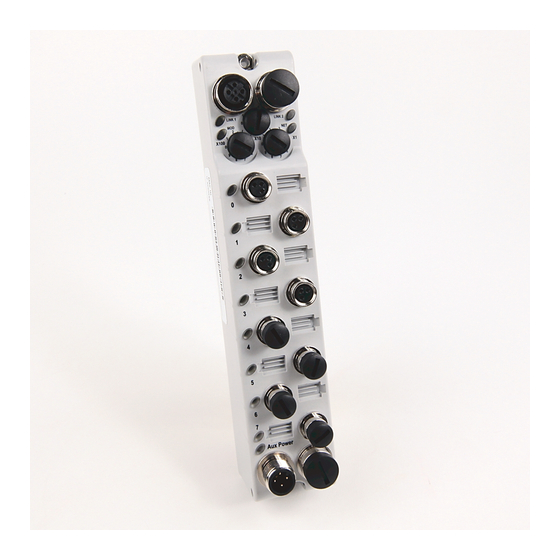
Page 81: Introduction
Auxiliary power indicator • Individual I/O status indicators for inputs LINK1 LINK2 Link 1 status indicator Link 2 status indicator Module status indicator Network status indicator X100 I/O status indicators Power status indicator Rockwell Automation Publication 1732E-UM003D-EN-E - November 2021... - Page 82 Output/input not energized. I/O status Yellow Output/input energized. IMPORTANT The Module Status Indicator will flash red and green for a maximum of 30 s while the module completes its POST (Power-On Self Test). Rockwell Automation Publication 1732E-UM003D-EN-E - November 2021...
-
Page 83: Fault And Status Reporting Between The Module And Controllers
Module Fault Word A communications fault sets all bits in the Module Fault Word. Module Tag Names and The 1732E-IB8M8SOER and 1732E-OB8M8SR has three sets of tags: Definitions • Configuration • Input • Output Rockwell Automation Publication 1732E-UM003D-EN-E - November 2021... -
Page 84: Tags Used
5 (I.Timestamp[5].OffOn or I.Timestamp[5].OnOff) has new data. This tag only clears when the controller acknowledges the new data or all events on the module are reset. For more information, see page Rockwell Automation Publication 1732E-UM003D-EN-E - November 2021... - Page 85 BOOL Erases all recorded events when transitioned from 0…1. Changes retrieval mechanism from sequential (when 0) to retrieving events on a per point basis according to value set O.RetrieveByPt BOOL in PointToRetrieve field. Rockwell Automation Publication 1732E-UM003D-EN-E - November 2021...
- Page 86 DINT[2] This value is initially zero. The first timestamp occurs when the module synchronizes with the Grandmaster clock. I.GrandmasterClockID DINT[2] The ID number of the Grandmaster clock that the module is synchronized to. Rockwell Automation Publication 1732E-UM003D-EN-E - November 2021...
- Page 87 Output Data to apply to unscheduled channels (those with a value of zero configured in ScheduleMask). Offset to add with TimestampOffset to determine absolute Time to apply Data to physical Output. Allows for O.Schedule.TimeStampOffset DINT range of approx. ±35 minutes from base TimestampOffset. Rockwell Automation Publication 1732E-UM003D-EN-E - November 2021...
- Page 88 Appendix A Module Tags Notes: Rockwell Automation Publication 1732E-UM003D-EN-E - November 2021...
-
Page 89: Communicate With Your Module
Output Configuration Per Point Input Output 1732E-OB8M8SR Configuration None Input Output (1) There is no Listen Only connection for the 1732E-OB8M8SR because consumed assembly data is dependent on data in the produced assembly. Rockwell Automation Publication 1732E-UM003D-EN-E - November 2021... - Page 90 CaptureOnOff – Enables capturing On to Off events on a per point basis. If cleared, that point will not record On to Off events. Useful to not use up buffer space on events user does not care about. Rockwell Automation Publication 1732E-UM003D-EN-E - November 2021...
- Page 91 Time stamps will be zero at power-up and after a time stamp is acknowledged. The time base and epoch of the timestamps are determined by the grand-master clock of the system. All data listed in this assembly is in Little Endian format, LSB first, in increasing byte order to MSByte last. Rockwell Automation Publication 1732E-UM003D-EN-E - November 2021...
- Page 92 Event Number 6 (32 bit) Event Point 6 Reserved (Must be 0) EventData6 142…143 Pad (16 Bits) 144…151 Input Time Stamp 7 (64 bit) 152…155 Event Number 7 (32 bit) Event Point 7 Reserved (Must be 0) Rockwell Automation Publication 1732E-UM003D-EN-E - November 2021...
- Page 93 Time stamps will be zero at power-up and after a time stamp is acknowledged. The time base and epoch of the timestamps are determined by the grand-master clock of the system. All data listed in this assembly is in Little Endian format, LSB first, in increasing byte order to MSByte last. Rockwell Automation Publication 1732E-UM003D-EN-E - November 2021...
- Page 94 IA_G0 = Idle Action Group 0 (0 = Apply Fault Value; 1= Hold Last State) Where: FV_G0 = Fault Value Group 0 (0 = OFF;1 = ON) IV_G0 = Idle Value Group 0 (0 = OFF;1 = ON) Rockwell Automation Publication 1732E-UM003D-EN-E - November 2021...
- Page 95 Data Ch2 Data Ch1 Data Ch0 Reserved (Ignored) ScheduleM Schedule Schedule Schedule Schedule Schedule Schedule Schedule Mask Mask Mask Mask Mask Mask Mask Reserved (Ignored) Timestamp Offset Schedule Timestamp Schedule[0].ID Schedule[0].SequenceNumber Schedule[0].OutputPointSelect Schedule[0].Data Rockwell Automation Publication 1732E-UM003D-EN-E - November 2021...
- Page 96 Schedule[6].OutputPointSelect Schedule[6].Data 76…79 Schedule[6]. TimestampOffset Schedule[7].ID Schedule[7].SequenceNumber Schedule[7].OutputPointSelect Schedule[7].Data 84…87 Schedule[7]. TimestampOffset Schedule[8].ID Schedule[8].SequenceNumber Schedule[8].OutputPointSelect Schedule[8].Data 92…95 Schedule[8]. TimestampOffset Schedule[9].ID Schedule[9].SequenceNumber Schedule[9].OutputPointSelect Schedule[9].Data 100…103 Schedule[9]. TimestampOffset Schedule[10].ID Schedule[10].SequenceNumber Schedule[10].OutputPointSelect Schedule[10].Data 108…111 Schedule[10]. TimestampOffset Rockwell Automation Publication 1732E-UM003D-EN-E - November 2021...
- Page 97 Schedule[xx].Data – Valid value 0 = OFF; 1 = ON Schedule[xx].TimestampOffset – Offset to add with ScheduleTimestamp (output bytes 12…19) to determine absolute Time to apply Data to physical Output. Allows for range of ~±35 Minutes from base ScheduleTimestamp. Rockwell Automation Publication 1732E-UM003D-EN-E - November 2021...
- Page 98 Reserved 16 bits (Must be zero) Schedule[10].State (8 bit) Schedule[10].SequenceNumber (8 bit) 90…91 Reserved 16 bits (Must be zero) Schedule[11].State (8 bit) Schedule[11].SequenceNumber (8 bit) 94…95 Reserved 16 bits (Must be zero) Schedule[12].State (8 bit) Schedule[12].SequenceNumber (8 bit) Rockwell Automation Publication 1732E-UM003D-EN-E - November 2021...
- Page 99 Timestamps are zero at power-up and after a timestamp is acknowledged. The time base and epoch of the timestamps are determined by the grandmaster clock of the system. All data listed in this assembly is in Little Endian format, LSB first, in increasing byte order to MSByte last. Rockwell Automation Publication 1732E-UM003D-EN-E - November 2021...
- Page 100 Appendix B Data Tables Notes: Rockwell Automation Publication 1732E-UM003D-EN-E - November 2021...
-
Page 101: Armorblock Module And Ethernet Communication
Ring network topologies. The network setup is simple and cost effective. Typical network topology is pictured below. Ethernet Network Topology RJ45 cable with D-coded M12 Ethernet Hub or connector Switch to PC Ethernet Card to ArmorBlock module Rockwell Automation Publication 1732E-UM003D-EN-E - November 2021... -
Page 102: Connecting To An Ethernet Network
In order to exchange I/O data with another device on Ethernet, that device must first originate a connection with the ArmorBlock via TCP/IP. Once an I/O connection is established via TCP/IP the I/O data is exchanged via UDP/IP. Rockwell Automation Publication 1732E-UM003D-EN-E - November 2021... -
Page 103: Duplicate Ip Address Detection
Maximum length is 48 characters. This is the IP address of the computer acting as the local Ethernet network Primary Domain Name System (DNS) Primary Name Server 0 (undefined) read/write server. Rockwell Automation Publication 1732E-UM003D-EN-E - November 2021... -
Page 104: Configure Using Studio 5000 Logix Designer Software
TCP/IP configuration, and diagnostic information. For more information on ArmorBlock module embedded web server capability, see ArmorBlock Embedded Web Server on page 105. Rockwell Automation Publication 1732E-UM003D-EN-E - November 2021... -
Page 105: Introduction
Appendix ArmorBlock Embedded Web Server Introduction Rockwell Automation offers enhanced ArmorBlock I/O modules for your EtherNet/IP control systems so that you can monitor data remotely via web pages. This chapter shows how you can use the ArmorBlock EtherNet/IP Dual Port 8- point Sequence of Events Input and Scheduled Output Modules web server. -
Page 106: Enable Or Disable The Web Server
2. Set the switches to the desired IP address and cycle power to the module. 3. In your web browser, enter the IP address of the adapter. The web server home page does not display Rockwell Automation Publication 1732E-UM003D-EN-E - November 2021... -
Page 107: Access The Home Page Of The Web Server
ArmorBlock I/O module prompts you to enter your user name and password. The user name is admin. The default password is password. Both are case sensitive. Default Access User Name: admin Password: password Rockwell Automation Publication 1732E-UM003D-EN-E - November 2021... -
Page 108: Navigate The Armorblock I/O
Offset From Master Clock by clicking Diagnostic Overview on the navigational panel on the left. Click the Diagnostic folder to expand the navigation, then click the Diagnostic Overview page. View the deviation between the local clock and its master clock in nanoseconds. Rockwell Automation Publication 1732E-UM003D-EN-E - November 2021... -
Page 109: Index
37 auto negotiate 104 download 43 auxiliary power edit 43 status indicators 81 process 37 configuration process overview 37 Configuration tab 41 BootP/DHCP configuration tab relation list 32 use 62 configuration tags 84 Rockwell Automation Publication 1732E-UM003D-EN-E - November 2021... - Page 110 EtherNet/IP 9 send 29 sends 52 EtherNet/IP network 27 separate 61 overview 12 stores 52 Event latching 14 timestamp 52 EventAck 68 timestamped 53 output tag 70 data-producing 10 EventNumber 64 EventOverflow 62 Rockwell Automation Publication 1732E-UM003D-EN-E - November 2021...
- Page 111 76 web server 107 latch event mask 76 host name 103 latch timestamp 65 how to latched data use 59 clear 70 how to use 59 Latching Timestamp 52 latching 62 Rockwell Automation Publication 1732E-UM003D-EN-E - November 2021...
- Page 112 OffsetTimestamp 74 Module Properties dialog 41 ON and OFF modules timestamp 51 overview 9 on-board buffer 64 Sequence of Events 61 operational monitor mode 47 data 105 operational mode 55 operational modes 63 Rockwell Automation Publication 1732E-UM003D-EN-E - November 2021...
- Page 113 35 Precision Time 13 setting 21 Transport Control 30 protocol signal CIP 13 propagate 72 message-based 10 sinking or sourcing wiring TCP/UDP/IP 9 use 51 time-transfer 13 software PTP 13 DHCP 33 Rockwell Automation Publication 1732E-UM003D-EN-E - November 2021...
- Page 114 Time Sync 80 timestamp 14 tag 67 64-bit 14 accuracy 73 acknowledge 61 acknowledged 63 data 19 falling edge 70 individual 14 ON and OFF 51 recorded 14 rising edge 70 transition 68 Rockwell Automation Publication 1732E-UM003D-EN-E - November 2021...
- Page 115 59 unique 73 Timestamp Latching 62 time-transfer protocol 13 time-transfer protocol 13 torque 22 Web Server transition 68 home page 107 input 70 web server 107 timestamp 68 log in 107 transitions 61 Rockwell Automation Publication 1732E-UM003D-EN-E - November 2021...
- Page 116 Notes Rockwell Automation Publication 1732E-UM003D-EN-E - November 2021...
- Page 117 ArmorBlock EtherNet/IP Dual Port 8-point Sequence of Events Input and Scheduled Output Modules User Manual Rockwell Automation Publication 1732E-UM003D-EN-E - November 2021...
- Page 118 Rockwell Automation maintains current product environmental compliance information on its website at rok.auto/pec. Allen-Bradley, ArmorBlock, ControlFLASH, ControlLogix, expanding human possibility, FactoryTalk, Integrated Architecture, Logix 5000, Rockwell Automation, RSLinx, RSLogix 5000, Studio 5000 Logix Designer, Studio 5000 Logix Emulate, and TechConnect are trademarks of Rockwell Automation, Inc.
Need help?
Do you have a question about the Allen-Bradley ArmorBlock 1732E-IB8M8SOER and is the answer not in the manual?
Questions and answers