Table of Contents
Advertisement
Quick Links
SLC ControlNet Scanner Module
Catalog Number 1747-SCNR
Use this document to help you install the ControlNet™ 1747-SCNR
Scanner module.
For information about
All manuals and user guides at all-guides.com
Publication 1747-IN059A-EN-P - February 2001
Installation Instructions
See page
2
2
3
4
5
6
6
8
10
11
17
18
Advertisement
Table of Contents

Related Manuals for Rockwell Automation Allen-Bradley SLC ControlNet 1747-SCNR


Summary of Contents for Rockwell Automation Allen-Bradley SLC ControlNet 1747-SCNR
-
Page 1: Table Of Contents
All manuals and user guides at all-guides.com Installation Instructions SLC ControlNet Scanner Module Catalog Number 1747-SCNR Use this document to help you install the ControlNet™ 1747-SCNR Scanner module. For information about See page preventing electrostatic discharge compliance to European Union Directives related publications module features preparing the module for installation... -
Page 2: Preventing Electrostatic Discharge
All manuals and user guides at all-guides.com SLC ControlNet Scanner Module Prevent Electrostatic Discharge The scanner module is sensitive to electrostatic discharge. Electrostatic discharge can damage integrated circuits or ATTENTION semiconductors if you touch backplane connector pins. Follow these guidelines when you handle the module: •... -
Page 3: Related Publications
All manuals and user guides at all-guides.com SLC ControlNet Scanner Module Low Voltage Directive This product is tested to meet Council Directive 73/23/EEC Low Voltage by applying the safety requirements of EN 61131-2 Equipment Requirements and Tests. For specific information required by EN 61131-2, see the appropriate sections in this publication as well as the following Allen-Bradley publications: •... -
Page 4: Module Features
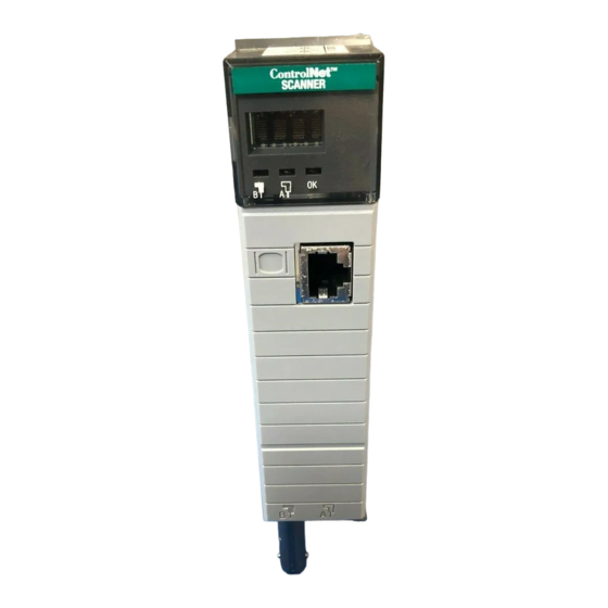
All manuals and user guides at all-guides.com SLC ControlNet Scanner Module Identify Scanner Module Features Use this illustration to identify the features of the 1747-SCNR Scanner module. Node Address and Status Display Channel B Displays scanner node address and status Status Indicator Channel A Module Status Indicator... -
Page 5: Preparing The Module For Installation
All manuals and user guides at all-guides.com SLC ControlNet Scanner Module Prepare for Module Installation Before you install your module, you need the following items: RSNetWorx for ™ ControlNet catalog number Personal Computer with 1747-SCNR Scanner Module 9357-CNETL3 ® ® Microsoft Windows Reference Manual, publication... -
Page 6: Selecting The Controlnet Node Address
All manuals and user guides at all-guides.com SLC ControlNet Scanner Module Select the ControlNet Node Address Select the ControlNet node address of the 1747-SCNR by setting the two 10-digit rotary switches on the top of the scanner. Valid switch settings range from 01 through 99. Zero (00) is not a valid node address. - Page 7 All manuals and user guides at all-guides.com SLC ControlNet Scanner Module 2. Select a slot for the module in the chassis. Choose any slot except the left-most slot of the first chassis, which is reserved for the SLC 500 processor. 3.
-
Page 8: Connecting To A Controlnet Network
All manuals and user guides at all-guides.com SLC ControlNet Scanner Module Connect to a ControlNet Network Connect the 1747-SCNR Scanner module to a ControlNet network via a tap with a 1m (39.4 in.) drop cable. Four Allen-Bradley ControlNet taps are available from Rockwell Automation as shown below. - Page 9 A to channel A on the scanner and from trunk-cable B to channel B on the scanner. 1. Rockwell Automation recommends using channel A for nonredundant media. For detailed information about planning and installing your ControlNet system, see the following information sources.
-
Page 10: Cables
Terminators (BNC-75Ω) 1786-XT 1. For a complete list of Allen-Bradley ControlNet cable system components that are available from Rockwell Automation and cable system components available from other suppliers, see the ControlNet Media System Component List, publication AG-2.2. Important: Install all wiring for your ControlNet system in... -
Page 11: Applying Chassis Power
All manuals and user guides at all-guides.com SLC ControlNet Scanner Module Apply Chassis Power Node Address and Status Display 30750-M When you apply chassis power, the module address and status display cycles through the following displays: 1. POST - The 1747-SCNR runs Power On Self Test. 2. - Page 12 All manuals and user guides at all-guides.com SLC ControlNet Scanner Module OK Indicator and Display Mnemonics The OK indicator is handled consistently with the ControlNet specifications for the Identity object. Sequence OK Alpanumeric Module Status Description Probable Recommended Indicator Display Word (M1 file) Cause Action...
- Page 13 All manuals and user guides at all-guides.com SLC ControlNet Scanner Module Sequence OK Alpanumeric Module Status Description Probable Recommended Indicator Display Word (M1 file) Cause Action Run time Green The scanner is The SLC If you want to in run mode. processor in put the scanner slot 0 is in run...
- Page 14 All manuals and user guides at all-guides.com SLC ControlNet Scanner Module Sequence OK Alpanumeric Module Status Description Probable Recommended Indicator Display Word (M1 file) Cause Action Run time Flashing 0x22 Connections View the Check to see if Green are configured Connection the 1747-SCNR but no...
- Page 15 All manuals and user guides at all-guides.com SLC ControlNet Scanner Module Sequence OK Alpanumeric Module Status Description Probable Recommended Indicator Display Word (M1 file) Cause Action Run time Flashing EDIT The scanlist in Edits have Finish Green the 1747-SCNR been enabled modifying the is being with...
- Page 16 All manuals and user guides at all-guides.com SLC ControlNet Scanner Module Sequence OK Alpanumeric Module Status Description Probable Recommended Indicator Display Word (M1 file) Cause Action Errors None Module is not Power supply Check power communicating fault. supply, cable connectors, and seat module firmly in chassis.
-
Page 17: Status Indicators
All manuals and user guides at all-guides.com SLC ControlNet Scanner Module Status Indicators The ControlNet status indicators inform you of the operational state of the ControlNet network. Indicator Probable Cause Recommended Action Color No power No action required or apply power. Steady Red Faulty unit Cycle power or reset unit. -
Page 18: Specifications
All manuals and user guides at all-guides.com SLC ControlNet Scanner Module Hazardous Location Approval The following information applies only to products marked with Hazardous Location Approval, when operating in hazardous locations: Products marked “CL I, DIV 2, GP A, B, C, D” are suitable for use in Class I Division 2 Groups A, B, C, D, Hazardous Locations and nonhazardous locations only. - Page 19 All manuals and user guides at all-guides.com SLC ControlNet Scanner Module Les informations suivantes ne concernent que les produits marqués pour une utilisation en environnements dangereux : Les produits marqués « CL I, DIV 2, GP A, B, C, D » ne conviennent qu’à une utilisation en environnements de Classe I Division 2 Groupes A, B, C, D dangereux et non dangereux.
- Page 20 Reference Manual 1747-RM623B-EN-P Allen-Bradley is a registered trademark of Rockwell Automation. SLC is a trademark of Rockwell Automation. ControlNet is a trademark of ControlNet International. Microsoft Windows is a registered trademark of Microsoft Corporation.
Need help?
Do you have a question about the Allen-Bradley SLC ControlNet 1747-SCNR and is the answer not in the manual?
Questions and answers