INVT SV-DA200 Operation Manual
Ac servo drives
Hide thumbs
Also See for SV-DA200:
- Operation manual (301 pages) ,
- Technical manual (45 pages) ,
- Technical manual (39 pages)
Table of Contents
Advertisement
Advertisement
Table of Contents

Related Manuals for INVT SV-DA200


Summary of Contents for INVT SV-DA200
- Page 1 INVT INDUSTRIAL TECHNOLOGY (SHANGHAI) CO.,LTD.
- Page 2 This manual presents installation and configuration, parameters setup, fault diagnoses and daily maintenance and relative precautions to customers. Please read this manual carefully before installation to ensure SV-DA200 drive is installed and operated properly to give full play to its excellent performance.
-
Page 3: Safety Precautions
SV-DA200 series AC servo drives Safety precautions Safety precautions Safety icons: Following safety precautions should be paid attention to before any installation, configuration, operation, maintenance and inspection: Check whether the AC power supply is the same as the rated voltage of the servo drive, otherwise fire, hurt, damage to the drive may occur. - Page 4 SV-DA200 series AC servo drives Safety precautions Do install the overcurrent protector, leakage current protector and emergency device and ensure the normal usage after wiring, otherwise electric shock, hurt and fire may occur. The leakage current may exceed 3.5mA during the drive running. Do ground with proper techniques and ensure the grounding resistor is less than 10Ω.
-
Page 5: Table Of Contents
SV-DA200 series AC servo drives Product overview Content Preface ..............................I Safety precautions ..........................II Content ............................... 1 Chapter 1 Product overview ......................3 1.1 Servo drive ..........................3 1.2 Servo motor ..........................4 ... - Page 6 SV-DA200 series AC servo drives Product overview 6.1 Basic control (P0 group parameters) ..................81 6.2 Autotuning control parameters (P1) ..................103 6.3 Motor control parameters (P2) ..................... 109 6.4 I/O management parameters (P3) ..................119 ...
- Page 7 SV-DA200 series AC servo drives Product overview Chapter 1 Product overview 1.1 Servo drive 1.1.1 Instruction to the drive DA200 series servo drive (100W~22kW) Specification Description 220V system input voltage 1P/3P AC220V(-15%)~240V(+10%) 47Hz~63Hz Power supply 400V system input voltage 3P AC380V(-15%)~440V(+10%) 47Hz~63Hz 10 inputs for standard type, pulse type and CANopen bus type;...
- Page 8 SV-DA200 series AC servo drives Product overview DA200 series servo drive (100W~22kW) Specification Description 1 Position control; 2 Speed control; 3 Torque control; 4 Position/Speed mode switching; 5 Speed/Torque mode switching; 6 Position/Torque Control mode mode switching; 7 Fully-closed loop control; 8 CANopen mode;...
- Page 9 SV-DA200 series AC servo drives Product overview DA200 series servo drive (100W~22kW) Specification Description input counterclockwise torque limit Internal speed 8 step speed can be switched according to the commands external control input ACC/DEC adjustment of ACC/DEC time setting and S curve setting...
- Page 10 SV-DA200 series AC servo drives Product overview DA200 series servo drive (100W~22kW) Specification Description occurs Operation temperature 0~45℃ Storage temperature -20~80℃(no frozen) Operation/storage humidity Operation/storage: ≤90%RH (no condensation) Environment IP degree IP20 Elevation Below 1000m altitude ≤5.88m/s2, 10~60Hz(Working at the resonance...
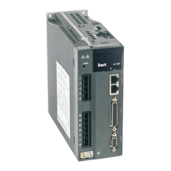
- Page 11 SV-DA200 series AC servo drives Product overview 1.1.2 External appearance of the drive Standard model S1:STO sele ction CN5:2nd encoder and STO CN4:USB port of upper PC LED display CHARGE light Operation panel Power su pply of main circuit...
- Page 12 SV-DA200 series AC servo drives Product overview 1.1.3 Naming of the drive Symbol Instruction Naming instance Product category SV: Servo system product ① Product series DA200: Product series ② 0R1: 100W 0R2: 200W 0R4: 400W 0R7: 750W 1R0: 1.0kW 1R5: 1.5kW 2R0: 2.0kW...
-
Page 13: Chapter 1 Product Overview
SV-DA200 series AC servo drives Product overview Function difference between different machine types: Small power range: 100W-5.5kW 16-bit Rotary PROFI Pulse RS48 Ether Motion Photoelectri Drive type Symbol analog transfor input encoder open c encoder input ○ × ○ ×... -
Page 14: Servo Motor
SV-DA200 series AC servo drives Product overview 1.1.5 Power ratings and cabinet volumes Input Output Cabinet Model Rated current Power Rated Voltage (V) volume (kW) current (A) SV-DA200-0R1-2 Single/Three phase 220 0.9/0.4 SV-DA200-0R2-2 Single/Three phase 220 1.8/0.8 SV-DA200-0R4-2 Single/Three phase 220 3.6/1.5... - Page 15 SV-DA200 series AC servo drives Product overview Note: “No. 3010004” in the nameplate is the motor model code (motor code for short). Please input this code into servo parameter P0.00 correctly (P0.00 is long parameter which can be set via keypad.
- Page 16 SV-DA200 series AC servo drives Product overview Symbol Instruction Naming instance 7R5: 7.5kW 011: 11kW 015: 15kW 022: 22kW …… A: 1000rpm B: 1500rpm ⑥ Rated speed E: 2000rpm F: 2500rpm G: 3000rpm 2: 220VAC ⑦ Voltage class 4: 380VAC...
-
Page 17: Cables
SV-DA200 series AC servo drives Product overview 1.3 Cables 1.3.1 Nameplate of cables 上海英威腾工业技术有限公司 INVT INDUSTRIAL TECHNOLOGY(SHANGHAI)CO.,LTD. 67002-00351 5m power flexible towline cable , 0.75mm cable diameter , 4PIN plastic piug , 7PIN 20A plug DAML-075-05-ABF-00 MADE IN CHINA 1.3.2 Naming of the power cables... - Page 18 SV-DA200 series AC servo drives Product overview Symbol Instruction Naming instance C: 4PIN metal plug D: 7PIN regular aviation plug YD28 E: 4PIN regular aviation plug YD18 N: 4PIN regular aviation plug YD32 S: Copper tube terminal SC B: Euro 7PIN 20A plug...
- Page 19 SV-DA200 series AC servo drives Product overview Symbol Instruction Naming instance Product series For internal use by manufacturer ① Encoder cable EL: Encoder cable ② 06: 6-core cable Cable number 09: 9-core cable ③ 15: 15-core cable 03: 3m 05: 5m Cable length ④...
-
Page 20: Braking Resistor Specification
SV-DA200 series AC servo drives Product overview 1.3.6 Naming of motor braking cables Symbol Instruction Naming instance Product series BRKL: motor brake cable ① 03: 3m 05: 5m Cable length ② 10: 10m 30: 30m A: 2PIN metal plug Plug on motor end B: 3PIN regular aviation plug ③... -
Page 21: Chapter 2 Installation Instruction
SV-DA200 series AC servo drives Installation instruction Chapter 2 Installation instruction 2.1 Drive dimension 2.1.1 A/B/C volume and dimension diagram 2.1.2 D volume and dimension diagram 2.1.3 F/F2 volume and dimension diagram ‐11‐ ... - Page 22 SV-DA200 series AC servo drives Installation instruction 2.1.4 G volume and dimension diagram 2.1.5 Detailed dimension table External dimension Installation dimension Installation Volume Model H(mm) W(mm) D(mm) A (mm) B1 (mm) B2 (mm) W1(mm) hole (mm) SV-DA200-0R1-2 SV-DA200-0R2-2 22.5 M4(Φ5)
-
Page 23: Drive Installation
SV-DA200 series AC servo drives Installation instruction 2.2 Drive installation 2.2.1 Installation mode 1) Base installation (there is a Φ5 installation hole at the lower left corner and upper right corner of the rear board respectively) 2) Bracket installation (the installation bracket is optional) - Page 24 SV-DA200 series AC servo drives Installation instruction 2.2.2 Installation space and direction Please install the servo drive vertically and keep enough installation space for good ventilation. Install fans if necessary to ensure the temperature inside the control cabinet is lower than 45℃.
-
Page 25: Motor Dimension
SV-DA200 series AC servo drives Installation instruction 2.3 Motor dimension Note: As motor structure and dimension may vary slightly with design modification, for those who are sensitive to the installation length of motor, please confirm the installation length with our business staff before ordering. - Page 26 SV-DA200 series AC servo drives Installation instruction 2.3.2 Outline and installation dimension for 60 bases (mm) L(mm) Motor model (2500-PPR/multi-turn absolute value/rotary transformer) W/o brake Permanent magnet brake SV-ML06-0R2G-2-□A□ SV-ML06-0R4G-2-□A□ SV-MH06-0R4G-2-□A□ Motor model L(mm) (17-bit single-turn encoder) W/o brake Electromagnetic brake SV-ML06-0R2G-2-3A□...
- Page 27 SV-DA200 series AC servo drives Installation instruction 2.3.3 Outline and installation dimension for 80 bases (mm) L(mm) Motor model (2500-PPR/multi-turn Permanent magnet Electromagnetic absolute value/rotary transformer) W/o brake brake brake SV-ML08-0R7G-2-□A□ SV-MH08-0R7G-2-□A□ L(mm) Motor model (17-bit single-turn encoder) W/o brake Electromagnetic brake SV-ML08-0R7G-2-3A□...
- Page 28 SV-DA200 series AC servo drives Installation instruction 2.3.4 Outline and installation dimension for 110 bases (mm) L(mm) Motor model (2500-PPR/multi-turn Permanent magnet Electromagnetic absolute value/rotary transformer) W/o brake brake brake SV-MM11-0R8E-2-□A□ SV-MM11-1R2G-2-□A□ SV-MM11-1R5G-2-□A□ SV-MM11-1R2E-2-□A□ SV-MM11-1R8G-2-□A□ ‐18‐ ...
- Page 29 SV-DA200 series AC servo drives Installation instruction 2.3.5 Outline and installation dimension for 130 bases (mm) L(mm) Motor model (2500-PPR/multi-turn Permanent magnet Electromagnetic absolute value/rotary transformer) W/o brake brake brake SV-MM13-1R0E-□-□A□ SV-MM13-1R5E-□-□A□ SV-MM13-2R0E-□-□A□ SV-MM13-3R0E-□-□A□ SV-MH13-0R8B-□-□A□ SV-MH13-1R3B-□-□A□ L(mm) Motor model (17-bit single-turn encoder)
- Page 30 SV-DA200 series AC servo drives Installation instruction 2.3.6 Outline and installation dimension for 180 bases (mm) ∅ 200 ∅13.5 L(mm) Motor model (2500-PPR/multi-turn Permanent magnet Electromagnetic absolute value/rotary transformer) W/o brake brake brake SV-MM18-3R0B-□-□A□ SV-MM18-4R4B-□-□A□ SV-MM18-5R5B-4-□A□ SV-MM18-7R5B-4-□A□ SV-SM18-7R5B shaft extension dimension (mm):...
-
Page 31: Motor Installation
SV-DA200 series AC servo drives Installation instruction 2.3.7 Outline and installation dimension for 200 bases (mm) L(mm) Motor model (2500-PPR/multi-turn Permanent magnet Electromagnetic absolute value/rotary transformer) W/o brake brake brake SV-MH20-011B-4-□A□ SV-MH20-015B-4-□A□ 2.3.8 Outline and installation dimension for 263 bases (mm) -
Page 32: Technical Parameters Of Servo Motor
SV-DA200 series AC servo drives Installation instruction 2.5 Technical parameters of servo motor 2.5.1 Motor specification (2500-PPR/multi-turn absolute /rotary transformer) Motor model Max. Max. Rotation inertia Weight Rated Rated Rated Rated Max. (2500-PPR/multi- turn transient transient standard/ with Voltage standard/... - Page 33 SV-DA200 series AC servo drives Installation instruction Motor model Max. Max. Rotation inertia Weight Rated Rated Rated Rated Max. (2500-PPR/multi- turn transient transient standard/ with Voltage standard/ power current torque speed speed absolute/ rotary current torque brake with brake (kW)
-
Page 34: Chapter 3 Wiring Instruction
SV-DA200 series AC servo drives Wiring instruction Chapter 3 Wiring instruction 3.1 System wiring Power L1 L2 L3 Breaker Used to cut off the circuit when power cable flows through overcurrent Noise filter Prevent the noise outside Safety input term inal signal is... - Page 35 SV-DA200 series AC servo drives Wiring instruction The input power cable must be able to withstand corresponding load current. The max rated temperature margin of input power cable should not be lower than 70℃ under continuous operation. ...
- Page 36 SV-DA200 series AC servo drives Wiring instruction 3.1.3 Cable diameter of main circuit Small power range (100W~5.5kW) main circuit cable diameter table Recommended cable Connectable cable Terminal Tightening diameter (mm diameter (mm Drive model screw torque L1\L2\L3 L1\L2\L3 (+), B2,...
- Page 37 SV-DA200 series AC servo drives Wiring instruction 3.1.4 EMI filter Drive model EMI filter model SV-DA200-0R1-2 SV-DA200-0R2-2 SV-DA200-0R4-2 FLT-P04006L-B SV-DA200-0R7-2 SV-DA200-1R0-4 SV-DA200-1R5-4 SV-DA200-1R0-2 SV-DA200-1R5-2 SV-DA200-2R0-4 FLT-P04016L-B SV-DA200-3R0-4 SV-DA200-2R0-2 SV-DA200-3R0-2 SV-DA200-4R4-4 FLT-P04032L-B SV-DA200-4R4-4 SV-DA200-5R5-4 SV-DA200-7R5-4 FLT-P04045L-B SV-DA200-011-4 SV-DA200-015-4 FLT-P04065L-B SV-DA200-022-4 FLT-P04100L-B Note: The EMI filter models in the table are the models of our company and they are used for power input terminal.
-
Page 38: Terminal Wiring Of The Main Circuit
SV-DA200 series AC servo drives Wiring instruction 3.2 Terminal wiring of the main circuit 3.2.1 Wiring diagram of single phase 220V (small power range: 100W~5.5kW) ‐28‐ ... - Page 39 SV-DA200 series AC servo drives Wiring instruction 3.2.2 Wiring diagram of three phase 220V/400V (small power range: 100W~5.5kW) ‐29‐ ...
- Page 40 SV-DA200 series AC servo drives Wiring instruction 3.2.3 Wiring diagram of three phase 400V (medium power range: 7.5kW~22kW) ‐30‐ ...
-
Page 41: Wiring Of Motor Power Cables
SV-DA200 series AC servo drives Wiring instruction 3.3 Wiring of motor power cables 3.3.1 2500-PPR 40, 60, 80-base 100W~750W motor power cable 3.3.2 17-bit or 23-bit 40, 60, 80-base 100W~750W motor power cable 3.3.3 110, 130-base 800W~1.5kW(220V) and 1kW~3kW(380V) motor power cable (except 130-base 17-bit single-turn with brake) ‐31‐ ... -
Page 42: Control I/O-Cn1 Terminal Layout
SV-DA200 series AC servo drives Wiring instruction 3.3.4 130, 180-base 2kW~4.4kW (220V) and 4.4kW~7.5kW (380V) motor power cable (except for 130-base 17-bit single-turn with brake) 3.3.5 200-base 11kW~22kW (380V) motor power cable 3.3.6 130-base 17-bit single-turn with brake 3.4 Control I/O-CN1 terminal layout Remark: This is the interface definition for standard model, refer to chapter 4 for terminal function and application. -
Page 43: Wiring Of Encoder-Cn2 Terminals
SV-DA200 series AC servo drives Wiring instruction 3.5 Wiring of encoder-CN2 terminals 3.5.1 CN2 terminals CN2 terminal function Name Function Remark V+/ SD+ Parallel encoder V+/Serial encoder data+ Signal of parallel encoder W+ Signal of parallel encoder A+ Signal of parallel encoder A-... - Page 44 SV-DA200 series AC servo drives Wiring instruction 3.5.3 2500-PPR 110, 130, 180, 200-base encoder cable 3.5.4 17-bit and 23-bit 40, 60, 80-base encoder cable 3.5.5 17-bit and 23-bit 110, 130, 180, 200-base encoder cable ‐34‐ ...
-
Page 45: Wiring Of 485/Can-Cn3 Terminals
SV-DA200 series AC servo drives Wiring instruction 3.5.6 Rotary transformer encoder cable 3.6 Wiring of 485/CAN-CN3 terminals Pin8 Pin1 CN3 terminal function Name Function Remark GND_CAN CAN chip power GND GND_485 485 chip power GND Unused 485 and CAN use the... -
Page 46: Nd Encoder And Sto-Cn5 Terminal Wiring
SV-DA200 series AC servo drives Wiring instruction CN4 USB port function Name Functions Remark Data - Data + The standard cable for USB micro to USB-A conversion is available. Signal ground 1, 4 Unused 3.8 2 encoder and STO-CN5 terminal wiring 3.8.1 Terminal interface and definition of small power range (100W~5.5kW) - Page 47 SV-DA200 series AC servo drives Wiring instruction 3.8.2 Terminal interface and definition of medium power range (7.5kW~22kW) CN5 terminal function table Pin no. Name Function Remark EXA+ Linear encoder (2 encoder) A+ EXA- Linear encoder encoder) A- EXB+ Linear encoder...
-
Page 48: Wiring Of Profibus-Dp Terminals
SV-DA200 series AC servo drives Wiring instruction 3.9 Wiring of PROFIBUS-DP terminals DP terminal function Remark Name Function Unused Unused B-Line Data + DP standard terminals and Request sending pin connection; this GND_BUS Isolation ground terminal is on extension +5V_BUS... -
Page 49: Chapter 4 Control Mode Applications
SV-DA200 series AC servo drives Control mode applications Chapter 4 Control mode applications 4.1 Standard wiring of the position mode …… ‐39‐ ... -
Page 50: Standard Wiring Of The Speed Mode
SV-DA200 series AC servo drives Control mode applications 4.2 Standard wiring of the speed mode …… ‐40‐ ... -
Page 51: Standard Wiring Of The Torque Mode
SV-DA200 series AC servo drives Control mode applications 4.3 Standard wiring of the torque mode …… ‐41‐ ... -
Page 52: Cn1 Function Instruction
SV-DA200 series AC servo drives Control mode applications 4.4 CN1 function instruction 4.4.1 Pins of CN1 terminal 4.4.2 Definition of CN1 terminals Sign Function Sign Function Analog input 1 PULS+ Differential command pulse + COM+ DI input common port PULS- Differential command pulse -... - Page 53 SV-DA200 series AC servo drives Control mode applications 4.4.3 Power supply signal Sign Pin no. Name Function COM- is the ground terminal of the 24V power. Its capacity is Internal 24V 100mA. If the actual load is higher than this value, the user power supply shall provide the power supply by themselves.
- Page 54 SV-DA200 series AC servo drives Control mode applications Position/fully-closed loop Speed mode mode Symbol Name Default Function Default Function Mark Mark value name value name direction drive direction drive disabled disabled Retention Speed Digital input 9 0x007 0x00E S-SIGN pulse clearing...
- Page 55 SV-DA200 series AC servo drives Control mode applications Torque mode MotionNet mode Symbol Name Default Mark Function Default Function Mark value name value name command sign stop Digital input DI10 0x006 Gain switching 0x000 Invalid Digital output Servo ready External brake...
- Page 56 SV-DA200 series AC servo drives Control mode applications Signal name Sign Function number Available mode information. Signal name Sign Function number Available mode Control mode switching 0x05 This function is the control signal of mode switching when P0.03 is 3, 4 and 5.
- Page 57 SV-DA200 series AC servo drives Control mode applications There are 1~8 signal selections for the internal speed command and 1~4 for the internal speed limit. Control mode P0.40 setting value SPD3 SPD2 SPD1 Parameters and setting value P0.46 internal speed 1 P0.47 internal speed 2...
- Page 58 SV-DA200 series AC servo drives Control mode applications These functions are the selections of 0~127 in the PTP (point-to-point) control mode. It has the same function with P5.20 and is valid when P0.20 is 2. The combination of 7 digital inputs is used to select the different PTP position of PtP0.00~PtP2.55 and the corresponding target speed, ACC/DEC time and the delay time of...
- Page 59 SV-DA200 series AC servo drives Control mode applications When the drive carries out HOME action, in some HOME mode, if the digital input is detected to be valid, HOME is finished. Refer to P5.10 for information. Signal name Sign Function number...
- Page 60 SV-DA200 series AC servo drives Control mode applications Signal name Sign Function number Available mode control mode, it has the same function with P5.20 when it is 100. Signal name Sign Function number Available mode Absolute position clearing PCLR 0x1F This function is used to clear the multi-turn absolute encoder.
- Page 61 SV-DA200 series AC servo drives Control mode applications When this digital input is valid, the turret is manual mode. Signal name Sign Function number Available mode Forward jogging of turret 0x32 When this digital input is valid, the turret is forward jogging.
- Page 62 SV-DA200 series AC servo drives Control mode applications This function is the state signal during control mode switching in output compound control mode. When it is valid, control mode 1 is switched to mode 2; if the function output is invalid, the control mode 2 is switched back to mode 1.
- Page 63 SV-DA200 series AC servo drives Control mode applications setting range of P3.59; there is 5% detection retention. Signal name Sign Function number Available mode PTP arrival PTPF 0x16 This function is output PTP arrival signal. Signal name Sign Function number...
- Page 64 SV-DA200 series AC servo drives Control mode applications Sign Pin no. Name Function PULS+ input 1 command input terminal In other control mode, the terminal is invalid PULS- Allowed Max. input pulse frequency: 4MHz in Position command pulse...
-
Page 65: Cn1 Wiring Instruction
SV-DA200 series AC servo drives Control mode applications 4.4.8 Analog output signals and functions Sign Pin no. Name Function Its output function definition can be set, and the Analog output 1 range and offset settings can be set Its output function definition can be set, and the... - Page 66 SV-DA200 series AC servo drives Control mode applications Users can use either the 24V power supply carried by the servo drive (it only can provide 100mA current) or 12V~24V power supply provided by the user. 4.5.2 Wiring of the pulse input circuit Connect mode 1: Differential mode ...
- Page 67 SV-DA200 series AC servo drives Control mode applications The max. input pulse frequency is 200kHz; if the local 24V power supply (it only can provide 100mA current) or the 24V power supply provided by the user is used, there is no need to connect to current limit resistor.
- Page 68 SV-DA200 series AC servo drives Control mode applications 4.5.3 Wiring of the analog input circuit There are three analog input circuits, AD1, AD2 and AD3, precision of AD1 is 16-bit (optional for standard models), precision of AD2 and AD3 is 12-bit (standard). The input impedance is 10kΩ. The input voltage range is -10V~+10V.
- Page 69 SV-DA200 series AC servo drives Control mode applications in the figure. They can be used to drive the relay coil or optical coupled load. The loading capacity is shown in the figure. When inductive loads such as relay coil are connected, a free wheel diode must be fitted as shown in the figure;...
- Page 70 SV-DA200 series AC servo drives Control mode applications 4.5.6 Wiring of the analog output circuit There are two analog output circuits in all. The output voltage range is -10V~10V. The Max output current is 3mA. 4.5.7 Wiring of the electromagnetic brake If the servo drive is used in the vertical shaft applications, the electromagnetic brake can be used to stop and keep the dropping speed when servo drive is power off.
-
Page 71: Cn5 Wiring Diagram
SV-DA200 series AC servo drives Control mode applications 4.6 CN5 wiring diagram 4.6.1 CN5 wiring diagram of small power range (100W~5.5kW) ‐61‐ ... - Page 72 SV-DA200 series AC servo drives Control mode applications 4.6.2 CN5 wiring diagram of medium power range (7.5kW~22kW) 4.6.3 2 encoder input circuit wiring of medium power range (7.5kW~22kW) Connection mode 1: Differential mode Differential pulse input signal voltage is ±5V, max frequency is 4MHz;...
- Page 73 SV-DA200 series AC servo drives Control mode applications Connection mode 2: Open collector mode 1 Control module is NPN type (common cathode): Control module is PNP type (common anode): Max input pulse frequency is 200kHz; if the local 24V power of DA200 (only 100mA power is available) or the 24V power provided by the user is used, there is no need to connect current limit resistor.
- Page 74 SV-DA200 series AC servo drives Control mode applications Connection mode 3: Open collector mode 2 Control module is NPN type (common cathode): Shielded Twisted cable pair EXA+ EXA- EXB+ EXB- EXZ+ EXZ- Control module DC12~24V side Drive side Control mode is PNP type (common cathode): ...
-
Page 75: Chapter 5 Running And Operation
SV-DA200 series AC servo drives Running and operation Chapter 5 Running and operation 5.1 Running 5.1.1 First powering on Please check following items before power on: 1) Wiring The power supply of the servo drive (L1, L2, L3, L1C, L2C or R, S and T) should be connect with proper techniques;... - Page 76 SV-DA200 series AC servo drives Running and operation 5.1.1.2 Checking after powering-on After switching on both of the control circuit and main circuit power supplies, if the power supply is OK, the LED indicator will display 0 first and then display 8. If there is no fault alarm of the servo drive, the LED on the front panel displays the current speed of the servo motor as default.
- Page 77 SV-DA200 series AC servo drives Running and operation Set P0.03 to “0”, the position control mode. Confirm the pulse output of the upper controller and adjust P0.23. Keep the pulse type the same with that of the upper controller. Please refer to the instruction of P0.23.
- Page 78 SV-DA200 series AC servo drives Running and operation 5.1.5 Running at the torque control mode Simple connection: Parameter Function Setting value P0.03 Mode selection Torque command P0.60 selection Torque command Set according to P0.61 direction selection requirement Analog input P0.62...
- Page 79 SV-DA200 series AC servo drives Running and operation Hereunder only some necessary parameters are listed: 1) Mode setting The control mode (position mode, speed mode, torque mode, fully-closed loop mode or other compound control mode) can be set through setting parameter P0.03 according to the control requirements on the site.
- Page 80 SV-DA200 series AC servo drives Running and operation When the digital input terminal configured as zero speed clamp (ZRS) is set to ON and P0.58 is at non-zero value, the servo motor stops running. When P0.58 is set to 1~3, the motor stops running based on the DEC time set by P0.55 and P0.57 in speed mode, and servo is in locked...
- Page 81 SV-DA200 series AC servo drives Running and operation 5.1.9 Sequence diagram 5.1.9.1 Sequence diagram of power-on and servo ON Power-on process Servo On process Main power Main circuit power-on Control power Control circuit power-on About 1.2s Microprocessor state Program initialization...
- Page 82 SV-DA200 series AC servo drives Running and operation 5.1.9.2 Sequence diagram of power loss during running Main power Main circuit power loss Note 1 Control circuit power disconnection Control power PWM output Servo has output Servo has no output Servo ready output...
- Page 83 SV-DA200 series AC servo drives Running and operation 5.1.9.4 Servo OFF sequence in running state 5.1.9.5 Sequence of fault alarm ‐73‐ ...
-
Page 84: Display And Operation
SV-DA200 series AC servo drives Running and operation 5.2 Display and operation 5.2.1 Display Keypad diagram: LED display character (reference table): Corresponding Corresponding Corresponding Corresponding display display display display symbol symbol symbol symbol character character character character 0 1 2 ... - Page 85 SV-DA200 series AC servo drives Running and operation Button function table: Function MODE Used to switch between different modes or return to previous menu Used to select parameter upwards or increase value DOWN Used to select parameter downwards or decrease value Press for a long time =SET (about 0.6 seconds)
- Page 86 SV-DA200 series AC servo drives Running and operation 5.2.2 State monitoring mode After power on, the screen will enter into “General monitoring mode”, display the parameters name for about 2.5 seconds and then display the current value. After pressing MODE key, UP/DOWN key can be used to switch monitoring parameters.
- Page 87 SV-DA200 series AC servo drives Running and operation DOWN DOWN DOWN MODE SHIFT MODE SHIFT DOWN DOWN SHIFT 5.2.4 Parameter setting MODE key can be used to switch into the parameters setting mode. SHIFT key can be used to select the group number of the monitoring parameters, UP/DOWN can be used to select the internal parameter number and pressing for a long time, it can be used to select the parameter number quickly.
- Page 88 SV-DA200 series AC servo drives Running and operation Sign Name Analog input 3 zero drift clear Inertia identification Absolute value encoder clear Note: The auxiliary functions can be operated only when servo is disabled, otherwise users cannot enter the auxiliary function menu.
- Page 89 SV-DA200 series AC servo drives Running and operation 5.2.5.5 Operation flowchart of inertia identification Press MODE key to the auxiliary function mode. Press UP/DOWN key to the menu, and press SET key to the interface. The interface will display . Press SET key to start the inertia identification.
- Page 90 SV-DA200 series AC servo drives Running and operation 5.2.6 Alarm display When the servo drive runs abnormally, it will perform fault alarm and stop automatically. At this time the panel will display the fault alarm warning sign. The format is ErXX-X, of which, XX is the master code and X is the sub code.
-
Page 91: Chapter 6 Detailed Parameter Description
SV-DA200 series AC servo drives Faults and solutions Chapter 6 Detailed parameter description P-position mode; S-speed mode; T-torque mode;F- fully-closed loop mode. The definition of direction: From the angle of facing motor shaft, the counterclockwise direction is forward (CCW for short); clockwise (CW) is reverse; in terms of speed and torque reference value, positive value means position direction and negative value means negative direction. - Page 92 SV-DA200 series AC servo drives Faults and solutions Setting range Default Unit Available mode P0.01 Encoder type 1~12 Generally, the system will set this parameter automatically after P0.00 is set correctly. In cases where encoder disconnection fault is reported during power up when motor is connected correctly, please check whether the drive supports motor encoder type, refer to chapter 1.1.3.
- Page 93 SV-DA200 series AC servo drives Faults and solutions Speed mode: Control the rotation speed of the servo motor with the internal or external speed command Torque mode: Control the torque of the servo motor with the internal or external torque command.
- Page 94 SV-DA200 series AC servo drives Faults and solutions Note: The switching mode is not limited by actual operation. Fully-closed loop mode: Use the linear encoder to detect the devices of control object and conduct information feedback position control. CANopen mode (CANopen type servo support)
- Page 95 SV-DA200 series AC servo drives Faults and solutions Data size 16bit Data format P0.05 Modbus address 1010,1011 CANopen address 0x2005, 0x00 Numerator of frequency Setting range Default Unit Available mode P0.06 division output coefficient 0~(2 10000 Setting range Default Unit...
- Page 96 SV-DA200 series AC servo drives Faults and solutions Torque limit mode Setting range Default Unit Available mode P0.09 setting This parameter is used to set the torque limit mode. In speed mode, the analog input 3 is set to the torque limit, and:...
- Page 97 SV-DA200 series AC servo drives Faults and solutions servo motor. If the absolute value of the torque command is larger than the value of this parameter, then the actual output torque will be limited by the parameter. Note: 1. These parameters are used with P0.09;...
- Page 98 SV-DA200 series AC servo drives Faults and solutions Main circuit DC voltage Voltage of control power Output voltage Vrms Output current Arms Drive temperature ℃ Torque limit Encoder feedback value pulse Rotor position to Z pulse pulse Load inertia ratio...
- Page 99 SV-DA200 series AC servo drives Faults and solutions Setting range Default Unit Available mode P0.18* Factory password 0~65536 This parameter is used to view and modify the menu. Data size 16bit Data format P0.18* Modbus address 1036,1037 CANopen address 0x2012, 0x00 6.1.2 Position control...
- Page 100 SV-DA200 series AC servo drives Faults and solutions Quadrature encoder pulse mode Remark: The pulse direction of the parameter can be reversed by P0.24 . Please refer to P0.24 for detailed information. Data size 16bit Data format P0.23 Modbus address...
- Page 101 SV-DA200 series AC servo drives Faults and solutions Below is the schematic diagram of the electronic gear ratio in the system: Example: Below is a case where 1 pulse is μm equivalent to a feed rate of 10 Mechanical specifications: Feed of the ball screw =10mm;...
- Page 102 SV-DA200 series AC servo drives Faults and solutions Data size 32bit Data format P0.27 Modbus address 1054,1055 CANopen address 0x201B, 0x00 Data size 32bit Data format P0.28 Modbus address 1056,1057 CANopen address 0x201C, 0x00 Data size 32bit Data format P0.29...
- Page 103 SV-DA200 series AC servo drives Faults and solutions Software limit of forward Setting range Default Unit Available mode P0.35 position control -1)~(2 reference unit This parameter is used to set the software limit of the forward position control. Note: The function is valid when it is above P0.36.
- Page 104 SV-DA200 series AC servo drives Faults and solutions The motor speed can be controlled by applying -10V~10V voltage between analog speed input terminals (AD1, GND, pin “1” and “5”) of CN1. In the factory default, the positive value means the forward Analog input direction and the negative value means the reverse direction.
- Page 105 SV-DA200 series AC servo drives Faults and solutions Note: 1. The default is the input signal from analog input terminal 1 of CN1 (AD1, GND and pin “1”,“5”). 2. This parameter is valid when the setting value of P0.40 is “1”.
- Page 106 SV-DA200 series AC servo drives Faults and solutions Setting range Default Unit Available mode P0.49 Internal speed 4/Speed limit 4 -20000~20000 r/min Setting range Default Unit Available mode P0.50 Internal speed 5 -20000~20000 r/min Setting range Default Unit Available mode P0.51...
- Page 107 SV-DA200 series AC servo drives Faults and solutions Data size 16bit Data format P0.51 Modbus address 1102,1103 CANopen address 0x2033, 0x00 Data size 16bit Data format P0.52 Modbus address 1104,1105 CANopen address 0x2034, 0x00 Data size 16bit Data format P0.53...
- Page 108 SV-DA200 series AC servo drives Faults and solutions ACC/DEC time of S curve is shown in the figure below: Note: 1. ACC/DEC time of S curve can only be used in the speed mode; 2. If the speed command is analog input, this function is invalid;...
- Page 109 SV-DA200 series AC servo drives Faults and solutions This parameter is used to set the position when P0.58 is 2 or 3. When P0.58 is 3, there is 10r/min delay when detection. Data size 16bit Data format P0.59 Modbus address...
- Page 110 SV-DA200 series AC servo drives Faults and solutions 1. The voltage of the analog torque command input corresponds to the changing gain of the motor command torque. 2. This parameter is valid when P0.60 is set to “1”. 3. The relation between the analog torque command input voltage and the torque, the default value is that each 1V corresponds to 10% of the rated torque.
- Page 111 SV-DA200 series AC servo drives Faults and solutions Set internal torque reference value via this parameter and take the rated torque of servo motor as 100%. This set value is the percentage value of rated torque of servo motor. Note: 1.
- Page 112 SV-DA200 series AC servo drives Faults and solutions Setting value Method Single circle Multiple circles Data size 16bit Data format P0.70 Modbus address 1140,1141 CANopen address 0x2046, 0x00 Absolute encoder Setting range Default Unit Available mode P0.71* multi-turn zeroing Clear the multi-turn absolute encoder via this parameter. The multi-turn data of the encoder will be cleared after this parameter is enabled while the single-turn data will remain unchanged, however, the absolute position feedback of the system will be cleared.
-
Page 113: Autotuning Control Parameters (P1)
SV-DA200 series AC servo drives Faults and solutions When P0.03 is 3 or 4, this parameter is used to set the exiting mode when the position mode can be switched to other control modes. Setting value Exiting mode Switch from position mode to other mode after positioning... - Page 114 SV-DA200 series AC servo drives Faults and solutions Mechanical structure Rigidity set Big handling, transmission equipment 0~13 Belt drive mechanism 5~16 Ball screw + Belt drive 5~16 Manipulator 15~22 Direct ball screw or rigid bodies 18~25 Data size 16bit Data format P1.03...
- Page 115 SV-DA200 series AC servo drives Faults and solutions ACC time constant of Setting range Default Unit Available mode P1.07 inertia identification 2~1000 This parameter is used to set the motor ACC time during the inertia identification. If the load inertia is large, the ACC time can be set to a large value to avoid the overload alarm.
- Page 116 SV-DA200 series AC servo drives Faults and solutions according to the self-adaptive result. The parameters related to 3 and 4 notch filters will be two notch filters valid updated according to the self-adaptive result. Resonance frequency Detect mechanical resonance frequency automatically but test mode does not set the parameters related to notch filter.
- Page 117 SV-DA200 series AC servo drives Faults and solutions Setting range Default Unit Available mode P1.24 notch filter Q value 0.50~16.00 1.00 This parameter is used to set the Q value (quality factor) of 1 notch filter Q=Center frequency of 1 notch filter/bandwidth of the notch.
- Page 118 SV-DA200 series AC servo drives Faults and solutions Data size 16bit Data format P1.31 Modbus address 1262,1263 CANopen address 0x211F,0x00 Setting range Default Unit Available mode P1.32 notch filter frequency 50~5000 5000 Setting range Default Unit Available mode P1.33 notch filter Q value 0.50~16.00...
-
Page 119: Motor Control Parameters (P2)
SV-DA200 series AC servo drives Faults and solutions Data size 16bit Data format P1.37 Modbus address 1274,1275 CANopen address 0x2125,0x00 vibration control Setting range Default Unit Available mode P1.38 frequency 0.0~200.0 Setting range Default Unit Available mode vibration control P1.39 filter factor 0.00~1.00... - Page 120 SV-DA200 series AC servo drives Faults and solutions This parameter is used to set 1 speed detection filter. Note: 5000 means there is no filter. Setting this parameter to a small value may reduce motor noise and speed fluctuation, but it also lower down the responsiveness.
- Page 121 SV-DA200 series AC servo drives Faults and solutions Data size 16bit Data format P2.10 Modbus address 1420,1421 CANopen address 0x220A, 0x00 Setting range Default Unit Available mode Speed feed-forward P2.11 filter time 0.00~64.00 0.50 This parameter is used to set the speed feed-forward filter time.
- Page 122 SV-DA200 series AC servo drives Faults and solutions 6.3.2 Gain switching Setting range Default Unit Available mode P2.20 gain setting This parameter is used to set the right adjustment. Setting value Mode gain is fixed. Gain switching invalid→PI action Gain switching valid→P action Note: 0x006 is the digital input low level valid and the high level valid is 0x106.
- Page 123 SV-DA200 series AC servo drives Faults and solutions fully-closed loop control. In the previous 1 gain, if the position command is not 0, it will switch to With position gain. command In the previous 2 gain, if the 0 position command lasts in the delay time, it will return to 1 gain.
- Page 124 SV-DA200 series AC servo drives Faults and solutions Data size 16bit Data format P2.25 Modbus address 1450,1451 CANopen address 0x2219,0x00 Setting range Default Unit Available mode Switching time of P2.26 position gain 0~10000 In position control, if the offset between P2.00 and P2.04 is large, setting this parameter can control the torque changing and vibration caused by increasing gain during switching from small gain to large gain.
- Page 125 SV-DA200 series AC servo drives Faults and solutions In the speed control, if set P2.27 to 3~5, when switching from 2 gain to 1 gain, it is the time from meeting the trigger conditions to the actual switching. Data size...
- Page 126 SV-DA200 series AC servo drives Faults and solutions Data size 16bit Data format P2.32 Modbus address 1464,1465 CANopen address 0x2220,0x00 Setting range Default Unit Available mode Switching level of P2.33 torque control 0~20000 Based on mode In the torque control, if set P2.31 to 3, it is necessary to set trigger condition of gain switching.
- Page 127 SV-DA200 series AC servo drives Faults and solutions torque compensation, it is necessary to be used in combination with P2.42. Data size 16bit Data format P2.43 Modbus address 1486,1487 CANopen address 0x222B,0x00 Setting range Default Unit Available mode P2.44 Torque command offset -500.0~500.0...
- Page 128 SV-DA200 series AC servo drives Faults and solutions Data size 16bit Data format P2.60 Modbus address 1520, 1521 CANopen address 0x223C, 0x00 Setting range Default Unit Available mode P2.61 Speed observer gain 1~1000 This parameter is used to set the gain of the speed observer. Increasing the setting value may increase the response speed of the actual speed, but the vibration and noise may be raised too.
-
Page 129: I/O Management Parameters (P3)
SV-DA200 series AC servo drives Faults and solutions 6.4 I/O management parameters (P3) 6.4.1 Digital input/output Input configuration of digital Setting range Default Unit Available mode P3.00 input 1 0x000~0x133 0x003 This parameter is used to select the configuration of the digital value 1 input function. It is a hex number. - Page 130 SV-DA200 series AC servo drives Faults and solutions PTP control trigger TRIG 0x11B 0x01B Vibration control switching input VS-SEL 0x11C 0x01C Fast stop Q-STOP 0x11D 0x01D PTP control stop PTP-ST 0x11E 0x01E Absolute position clearing PCLR 0x11F 0x01F Internal position command 5...
- Page 131 SV-DA200 series AC servo drives Faults and solutions 0x000~0x133 0x01A Input configuration of digital 7 Setting range Default Unit Available mode P3.06 0x000~0x133 0x001 Input configuration of digital 8 Setting range Default Unit Available mode P3.07 0x000~0x133 0x002 Input configuration of digital 9...
- Page 132 SV-DA200 series AC servo drives Faults and solutions Setting value Optical coupler Optical coupler Signal name Sign Available mode non-conduction conduction valid valid Invalid — 0x100 0x000 Servo ready output 0x101 0x001 Servo operation output 0x102 0x002 Fault output 0x103...
- Page 133 SV-DA200 series AC servo drives Faults and solutions Setting range Default Unit Available mode P3.11 Output configuration of digital 2 0x000~0x11F 0x003 Setting range Default Unit Available mode P3.12 Output configuration of digital 3 0x000~0x11F 0x007 Setting range Default Unit Available mode P3.13...
- Page 134 SV-DA200 series AC servo drives Faults and solutions 6.4.2 Analog input / output adjustment Setting range Default Unit Available mode P3.20 Offset of analog input 1 -10.000~10.000 0.000 This parameter can be used to adjust the analog input 1 to improve the effective accuracy of the analog input.
- Page 135 SV-DA200 series AC servo drives Faults and solutions Data size 16bit Data format P3.21 Modbus address 1642,1643 CANopen address 0x2315,0x00 Setting range Default Unit Available mode Voltage protection of P3.22 analog input 1 0.000~10.000 0.000 This parameter is used to set the overvoltage protection of analog input 1.
- Page 136 SV-DA200 series AC servo drives Faults and solutions 2. The input voltage should be no more than 10V, otherwise damage may occur to the drive. Data size 32bit Data format P3.25 Modbus address 1650,1651 CANopen address 0x2319,0x00 Function selection of...
- Page 137 SV-DA200 series AC servo drives Faults and solutions Setting value Definition Unit Invalid Motor speed r/min Speed of position command r/min Internal position command pulse(Encoder unit) Speed command r/min Torque command 0.1% Torque feedback 0.1% Command position deviation reference unit...
- Page 138 SV-DA200 series AC servo drives Faults and solutions Note: 1. If the actual output speed is more than 3000r/min, AO1 output is 10V. Please select the gain according to the actual range of the parameter. 2. When P3.30 and P3.32 select other functions, the gain setting is the same.
- Page 139 SV-DA200 series AC servo drives Faults and solutions 6.4.3 Digital input / output settings Setting range Default Unit Available mode P3.40 Travel limit switch shield This parameter is used to set whether the digital input configured as forward drive disabling (0x001 or 0x101) and reverse drive disabling (0x002 or 0x102) is valid or not.
- Page 140 SV-DA200 series AC servo drives Faults and solutions This parameter can set whether the digital input configured as command pulse disabling (0x008 or x0108) among P3.00~P3.09 is valid or not. If command pulse disabling function needs to be blocked, this parameter will do the trick.
- Page 141 SV-DA200 series AC servo drives Faults and solutions of output continues until passing the set time by P3.52. Data size 16bit Data format P3.51 Modbus address 1702,1703 CANopen address 0x2333,0x00 Setting range Default Unit Available mode Hold time of position arrival P3.52...
- Page 142 SV-DA200 series AC servo drives Faults and solutions This parameter is used to set the locked time of the servo after braking in the locked state. The servo is OFF in the locked state, the digital output state configured as BRK (0x005 or 0x105) is invalid.
- Page 143 SV-DA200 series AC servo drives Faults and solutions Negative-direction torque limit 0.1%/V Note: If P3.70 is 2 and P0.09 is 0 or 4, the analog input 3 corresponds to the positive torque limit internally and P0.62~P0.65, P3.23~P3.25 correspond to the negative torque limit internally.
- Page 144 SV-DA200 series AC servo drives Faults and solutions Negative [+voltage] → [negative],[- voltage] → [positive] polarity Data size 16bit Data format P3.74 Modbus address 1748,1749 CANopen address 0x234A,0x00 Setting range Default Unit Available mode Voltage protection of P3.75 analog input 3 0.000~10.000...
-
Page 145: Extension And Application (P4)
SV-DA200 series AC servo drives Faults and solutions Data size 16bit Data format P3.90 Modbus address 1780,1781 CANopen address 0x235A,0x00 6.5 Extension and application (P4) 6.5.1 Communication setting 485 local communication Setting range Default Unit Available mode P4.01 address 1~255 This parameter is used to set local (slave) communication address of 485 serial communication. - Page 146 SV-DA200 series AC servo drives Faults and solutions This parameter is used to set the 485 communication parity mode and it only supports RTU mode. Setting value Baud rate None (N, 8, 1) Even (E, 8, 1) Odd (O, 8, 1)
- Page 147 SV-DA200 series AC servo drives Faults and solutions Setting value Meaning Free-run DC mode(sync0) Data size 16bit Data format P4.08 Modbus address 1816, 1817 CANopen address 0x2408, 0x00 Setting range Default Unit Available mode EtherCAT fault detection P4.09 time 0~1000 Set EtherCAT communication fault detection time.
- Page 148 SV-DA200 series AC servo drives Faults and solutions Setting range Default Unit Available mode P4.13* Bus speed command -20000~20000 r/min If P4.10 is 1, the drive speed command can be set via this parameter. Data size 16bit Data format P4.13*...
- Page 149 SV-DA200 series AC servo drives Faults and solutions If P4.10 is 1, this parameter can be used to set the switching command of electronic gear ratio. Denominator of actual Setting value Molecule of actual electronic gear ratio electronic gear ratio Molecule of 1 electronic gear ratio (P0.25)
- Page 150 SV-DA200 series AC servo drives Faults and solutions If P4.10 is 1, this parameter can be used to set the torque limit switching control. Setting value Function Disabled Enabled Data size 16bit Data format P4.21* Modbus address 1842,1843 CANopen address...
- Page 151 SV-DA200 series AC servo drives Faults and solutions Action P4.30 Setting value During deceleration After stopping Coast to stop Keep the inertia operation state Dynamic brake to stop Keep the inertia operation state Dynamic brake stop Dynamic braking state External dynamic brake acts...
- Page 152 SV-DA200 series AC servo drives Faults and solutions This parameter is used to set the regenerative brake mode and overload protection mode. Setting value Regenerative brake and overload protection Disabled (no regenerative brake) Embedded External Data size 16bit Data format P4.34...
- Page 153 SV-DA200 series AC servo drives Faults and solutions Setting range Default Unit Available mode P4.41 Reverse speed limit -20000~0 -20000 r/min This parameter is used to set the max. speed limit of reverse speed command. Note: The default value and setting range of the parameter is relative to the drive power level.
- Page 154 SV-DA200 series AC servo drives Faults and solutions initialization is completed. Data size 32bit Data format P4.54 Modbus address 1908,1909 CANopen address 0x2436,0x00 6.5.4 Fully-closed loop control Setting range Default Unit Available mode Frequency division molecular of P4.60 external linear encoder This parameter is used to set the frequency division molecular of external encoder.
- Page 155 SV-DA200 series AC servo drives Faults and solutions Data size 16bit Data format P4.65 Modbus address 1930,1931 CANopen address 0x2441,0x00 Setting range Default Unit Available mode External grating pulse P4.67 output mode of AB phase In fully-closed loop mode, this parameter is used to set the signal source of pulse feedback output.
- Page 156 SV-DA200 series AC servo drives Faults and solutions Setting range Default Unit Available mode P4.78 MotionNet node number 0~63 Set communication node number of local machine (slave station) in MotionNet communication. Data size 16bit Data format P4.78 Modbus address 1956, 1957...
- Page 157 Unit Available mode PPO type of DP P4.86 communication This parameter is used to set the frame type of PROFIBUS-DP communication. Note: SV-DA200 only supports PROFIBUS-DPV0 and the PPO only supports 5. Data size 16bit Data format P4.86 Modbus address...
- Page 158 SV-DA200 series AC servo drives Faults and solutions CANopen heartbeat cycle of the salve station. Data size 16bit Data format P4.88 Modbus address 1976,1977 CANopen address 0x2458,0x00 Automatic stop at Setting range Default Unit Available mode P4.89 CANopen disconnection Set whether to stop at CANopen disconnection by this parameter:...
- Page 159 SV-DA200 series AC servo drives Faults and solutions After this operation, all parameters (P0~P6 group) can be restored to the default value. Setting value Function Disabled Enabled Data size 16bit Data format P4.92* Modbus address 1984,1985 CANopen address 0x245C,0x00 Reading enable of fault...
-
Page 160: Program Jog, Homing And Ptp Control (P5)
SV-DA200 series AC servo drives Faults and solutions initialize the data of the relative parameters. Data size 16bit Data format P4.97* Modbus address 1994,1995 CANopen address 0x2461,0x00 Setting range Default Unit Available mode EEPROM data fault block of P4.98* communication encoder This parameter can be used to block the no data and data error fault of encoder EEPROM. - Page 161 SV-DA200 series AC servo drives Faults and solutions (waiting time P5.04→reverse moving P5.01→waiting time P5.04→forward moving P5.01) × cycle time P5.05 (waiting time P5.04→forward or reverse moving P5.01) × cycle 1 time Data size 16bit Data format P5.00 Modbus address...
- Page 162 SV-DA200 series AC servo drives Faults and solutions Setting range Default Unit Available mode P5.05 JOG cycle times 0~10000 This parameter is used to set the JOG cycle times. Please refer to P5.00. Data size 16bit Data format P5.05 Modbus address...
- Page 163 SV-DA200 series AC servo drives Faults and solutions Data size 16bit Data format P5.10 Modbus address 2020,2021 CANopen address 0x2505,0x00 Homing automatically Setting range Default Unit Available mode P5.11 after power on This parameter is used to set whether it can return to home automatically after power on.
- Page 164 SV-DA200 series AC servo drives Faults and solutions Setting range Default Unit Available mode P5.16 Correlated action of homing Set the correlated action of homing via this parameter Setting value Function No action To the designated target position To the specified 0 PTP position.
- Page 165 SV-DA200 series AC servo drives Faults and solutions function. 128-2047 Invalid 2048 Forced to stop Example: Writing PTP signal 3 means to trigger the PTP program 3. Data size 16bit Data format P5.20* Modbus address 2040,2041 CANopen address 0x2514,0x00 Setting range...
- Page 166 SV-DA200 series AC servo drives Faults and solutions Data size 16bit Data format P5.21 Modbus address 2042,2043 CANopen address 0x2515,0x00 Data size 16bit Data format P5.22 Modbus address 2044,2045 CANopen address 0x2516,0x00 Data size 16bit Data format P5.23 Modbus address...
- Page 167 SV-DA200 series AC servo drives Faults and solutions Setting range Default Unit Available mode P5.41 04 ACC/DEC time 0~32767 Setting range Default Unit Available mode P5.42 05 ACC/DEC time 0~32767 Setting range Default Unit Available mode P5.43 06 ACC/DEC time...
- Page 168 SV-DA200 series AC servo drives Faults and solutions Data size 16bit Data format P5.44 Modbus address 2088,2089 CANopen address 0x252C,0x00 Data size 16bit Data format P5.45 Modbus address 2090,2091 CANopen address 0x252D,0x00 Data size 16bit Data format P5.46 Modbus address...
- Page 169 SV-DA200 series AC servo drives Faults and solutions Setting range Default Unit Available mode P5.64 11 delay time 0~32767 3500 Setting range Default Unit Available mode P5.65 12 delay time 0~32767 4000 Setting range Default Unit Available mode P5.66 13 delay time...
- Page 170 SV-DA200 series AC servo drives Faults and solutions Data size 16bit Data format P5.67 Modbus address 2134,2135 CANopen address 0x2543,0x00 Data size 16bit Data format P5.68 Modbus address 2136,2137 CANopen address 0x2544,0x00 Setting range Default Unit Available mode P5.69 PTP trigger buffer switch After point trigger buffer is enabled, 8 buffer can be received consecutively by sequence.
-
Page 171: Application Function (P6)
SV-DA200 series AC servo drives Faults and solutions Setting range Default Unit Available mode P5.74 Digital output mode of PTP Setting value Function Output before PTP arrival Output after PTP arrival Single point output+output before PTP arrival Single point output+output after PTP arrival... - Page 172 SV-DA200 series AC servo drives Faults and solutions Setting range Default Unit Available mode P6.03 Position latch save mode Position latch save mode can be set via this parameter: Setting value Function Do not save Save Data size 16bit Data format P6.03...
- Page 173 SV-DA200 series AC servo drives Faults and solutions Setting range Default Unit Available mode P6.21 Turret number 1~128 piece This parameter is used to set turret number. Data size 16bit Data format P6.21 Modbus address 2242, 2243 CANopen address 0x2615, 0x00...
- Page 174 SV-DA200 series AC servo drives Faults and solutions Data size 16bit Data format P6.33 Modbus address 2266, 2267 CANopen address 0x2621, 0x00 Gantry synchronous Setting range Default Unit Available mode P6.34 compensation torque filter 0.00~64.00 0.00 This parameter is used to set the time constant of gantry synchronous compensation torque filter.
-
Page 175: Ptp (Point-To-Point) Control (Ptp0, Ptp1, Ptp2)
SV-DA200 series AC servo drives Faults and solutions Data size 16bit Data format P6.39 Modbus address 2278, 2279 CANopen address 0x2627, 0x00 Gantry synchronization Setting range Default Unit Available mode P6.40 alignment approaching speed 1~60 r/min This parameter is used to set the gantry synchronization alignment approaching speed: the speed of servo in approaching alignment sensor again after contacting two alignment sensors. - Page 176 SV-DA200 series AC servo drives Faults and solutions Bit5 OVLP Overlap, the PTP can be overlapped with the next PTP Bit6~7 CMD Position command, 0:incremental position, 1:absolute position INS: OVLP: Relation between INS and OVLP: Note: 1.
- Page 177 SV-DA200 series AC servo drives Faults and solutions 2. INS has higher priority against OVLP; if PTP 1 OVLP and PTP 2 INS are enabled at the same time, PTP 1 OVLP is invalid 3. Two PTPs which have opposite operation direction cannot be overlapped...
- Page 178 SV-DA200 series AC servo drives Faults and solutions Setting range Default Unit Available mode control word PtP0.30 0~0x7FFFFFFF 0x00000000 Setting range Default Unit Available mode control word PtP0.32 0~0x7FFFFFFF 0x00000000 Setting range Default Unit Available mode control word PtP0.34...
- Page 179 SV-DA200 series AC servo drives Faults and solutions Setting range Default Unit Available mode control word PtP0.70 0~0x7FFFFFFF 0x00000000 Setting range Default Unit Available mode control word PtP0.72 0~0x7FFFFFFF 0x00000000 Setting range Default Unit Available mode control word PtP0.74...
- Page 180 SV-DA200 series AC servo drives Faults and solutions Data size 32bit Data format PtP0.10 Modbus address 3220,3221 CANopen address 0x2B0A,0x00 Data size 32bit Data format PtP0.12 Modbus address 3224,3225 CANopen address 0x2B0C,0x00 Data size 32bit Data format PtP0.14 Modbus address...
- Page 181 SV-DA200 series AC servo drives Faults and solutions Data size 32bit Data format PtP0.50 Modbus address 3300,3301 CANopen address 0x2B32,0x00 Data size 32bit Data format PtP0.52 Modbus address 3304,3305 CANopen address 0x2B34,0x00 Data size 32bit Data format PtP0.54 Modbus address...
- Page 182 SV-DA200 series AC servo drives Faults and solutions Data size 32bit Data format PtP0.90 Modbus address 3380,3381 CANopen address 0x2B5A,0x00 Data size 32bit Data format PtP0.92 Modbus address 3384,3385 CANopen address 0x2B5C,0x00 Data size 32bit Data format PtP0.94 Modbus address...
- Page 183 SV-DA200 series AC servo drives Faults and solutions Setting range Default Unit Available mode PtP0.33 position -1)~(2 reference unit Setting range Default Unit Available mode PtP0.35 position -1)~(2 reference unit Setting range Default Unit Available mode PtP0.37 position -1)~(2 reference unit...
- Page 184 SV-DA200 series AC servo drives Faults and solutions Setting range Default Unit Available mode PtP0.73 position -1)~(2 reference unit Setting range Default Unit Available mode PtP0.75 position -1)~(2 reference unit Setting range Default Unit Available mode PtP0.77 position -1)~(2 reference unit...
- Page 185 SV-DA200 series AC servo drives Faults and solutions Data 32bit Data format PtP0.13 Modbus address 3226,3227 CANopen address 0x2B0D,0x00 Data 32bit Data format PtP0.15 Modbus address 3230,3231 CANopen address 0x2B0F,0x00 Data 32bit Data format PtP0.17 Modbus address 3234,3235 CANopen address...
- Page 186 SV-DA200 series AC servo drives Faults and solutions Data 32bit Data format PtP0.53 Modbus address 3306,3307 CANopen address 0x2B35,0x00 Data 32bit Data format PtP0.55 Modbus address 3310,3311 CANopen address 0x2B37,0x00 Data 32bit Data format PtP0.57 Modbus address 3314,3315 CANopen address...
- Page 187 SV-DA200 series AC servo drives Faults and solutions Data 32bit Data format PtP0.93 Modbus address 3386,3387 CANopen address 0x2B5D,0x00 Data 32bit Data format PtP0.95 Modbus address 3390,3391 CANopen address 0x2B5F,0x00 Data 32bit Data format PtP0.97 Modbus address 3394,3395 CANopen address...
- Page 188 SV-DA200 series AC servo drives Faults and solutions Setting range Default Unit Available mode PtP1.32 control word 0~0x7FFFFFFF 0x00000000 Setting range Default Unit Available mode PtP1.34 control word 0~0x7FFFFFFF 0x00000000 Setting range Default Unit Available mode PtP1.36 control word 0~0x7FFFFFFF...
- Page 189 SV-DA200 series AC servo drives Faults and solutions Setting range Default Unit Available mode PtP1.72 control word 0~0x7FFFFFFF 0x00000000 Setting range Default Unit Available mode PtP1.74 control word 0~0x7FFFFFFF 0x00000000 Setting range Default Unit Available mode PtP1.76 control word 0~0x7FFFFFFF...
- Page 190 SV-DA200 series AC servo drives Faults and solutions Data size 32bit Data format PtP1.10 Modbus address 3420,3421 CANopen address 0x2C0A,0x00 Data size 32bit Data format PtP1.12 Modbus address 3424,3425 CANopen address 0x2C0C,0x00 Data size 32bit Data format PtP1.14 Modbus address...
- Page 191 SV-DA200 series AC servo drives Faults and solutions Data size 32bit Data format PtP1.50 Modbus address 3500,3501 CANopen address 0x2C32,0x00 Data size 32bit Data format PtP1.52 Modbus address 3504,3505 CANopen address 0x2C34,0x00 Data size 32bit Data format PtP1.54 Modbus address...
- Page 192 SV-DA200 series AC servo drives Faults and solutions Data size 32bit Data format PtP1.90 Modbus address 3580,3581 CANopen address 0x2C5A,0x00 Data size 32bit Data format PtP1.92 Modbus address 3584,3585 CANopen address 0x2C5C,0x00 Data size 32bit Data format PtP1.94 Modbus address...
- Page 193 SV-DA200 series AC servo drives Faults and solutions Setting range Default Unit Available mode PtP1.31 position -1)~(2 reference unit Setting range Default Unit Available mode PtP1.33 position -1)~(2 reference unit Setting range Default Unit Available mode PtP1.35 position -1)~(2 reference unit...
- Page 194 SV-DA200 series AC servo drives Faults and solutions Setting range Default Unit Available mode PtP1.71 position -1)~(2 reference unit Setting range Default Unit Available mode PtP1.73 position -1)~(2 reference unit Setting range Default Unit Available mode PtP1.75 position -1)~(2 reference unit...
- Page 195 SV-DA200 series AC servo drives Faults and solutions Data size 32bit Data format PtP1.09 Modbus address 3418,3419 CANopen address 0x2C09,0x00 Data size 32bit Data format PtP1.11 Modbus address 3422,3423 CANopen address 0x2C0B,0x00 Data size 32bit Data format PtP1.13 Modbus address...
- Page 196 SV-DA200 series AC servo drives Faults and solutions Data size 32bit Data format PtP1.49 Modbus address 3498,3499 CANopen address 0x2C31,0x00 Data size 32bit Data format PtP1.51 Modbus address 3502,3503 CANopen address 0x2C33,0x00 Data size 32bit Data format PtP1.53 Modbus address...
- Page 197 SV-DA200 series AC servo drives Faults and solutions Data size 32bit Data format PtP1.89 Modbus address 3578,3579 CANopen address 0x2C59,0x00 Data size 32bit Data format PtP1.91 Modbus address 3582,3583 CANopen address 0x2C5B,0x00 Data size 32bit Data format PtP1.93 Modbus address...
- Page 198 SV-DA200 series AC servo drives Faults and solutions Setting range Default Unit Available mode control word PtP2.28 0~0x7FFFFFFF 0x00000000 Setting range Default Unit Available mode control word PtP2.30 0~0x7FFFFFFF 0x00000000 Setting range Default Unit Available mode control word PtP2.32...
- Page 199 SV-DA200 series AC servo drives Faults and solutions Data size 32bit Data format PtP2.10 Modbus address 3620,3621 CANopen address 0x2D0A,0x00 Data size 32bit Data format PtP2.12 Modbus address 3624,3625 CANopen address 0x2D0C,0x00 Data size 32bit Data format PtP2.14 Modbus address...
- Page 200 SV-DA200 series AC servo drives Faults and solutions Data size 32bit Data format PtP2.50 Modbus address 3700,3701 CANopen address 0x2D32,0x00 Data size 32bit Data format PtP2.52 Modbus address 3704,3705 CANopen address 0x2D34,0x00 Data size 32bit Data format PtP2.54 Modbus address...
- Page 201 SV-DA200 series AC servo drives Faults and solutions Setting range Default Unit Available mode PtP2.35 position -1)~(2 reference unit Setting range Default Unit Available mode PtP2.37 position -1)~(2 reference unit Setting range Default Unit Available mode PtP2.39 position -1)~(2 reference unit...
- Page 202 SV-DA200 series AC servo drives Faults and solutions Data size 32bit Data format PtP2.17 Modbus address 3634,3635 CANopen address 0x2D11,0x00 Data size 32bit Data format PtP2.19 Modbus address 3638,3639 CANopen address 0x2D13,0x00 Data size 32bit Data format PtP2.21 Modbus address...
-
Page 203: State Monitoring
SV-DA200 series AC servo drives Faults and solutions 6.9 State monitoring 6.9.1 User monitoring parameters (R0 group) Display range Precision Unit R0.00 Motor speed -9999.9~9999.9 r/min Display the actual speed of the servo motor Note: This parameter is processed with filtering when displaying. - Page 204 SV-DA200 series AC servo drives Faults and solutions Display range Precision Unit R0.06 Current torque -500.0~500.0 Display the actual torque at present. If the rated torque of servo motor is 100.0%, the actual value will be converted to percentage value to be displayed.
- Page 205 SV-DA200 series AC servo drives Faults and solutions Display range Precision Unit R0.13 Encoder feedback value 0~(2 pulse Display the current encoder feedback value. Data size 32bit Data format R0.13 Modbus address 4030,4031 CANopen address 0x300D,0x00 Display range Precision Unit R0.14...
- Page 206 SV-DA200 series AC servo drives Faults and solutions Display the denominator coefficient of actual electric gear ratio Data size 32bit Data format R0.19 Modbus address 4042,4043 CANopen address 0x3013,0x00 Display range Precision Unit R0.20 Position command speed -9999.9~9999.9 r/min Display the speed value corresponds to the position command.
- Page 207 SV-DA200 series AC servo drives Faults and solutions Display the circles of multi-turn encoder. Data size 16bit Data format R0.25 Modbus address 4054, 4055 CANopen address 0x3019, 0x00 Display range Precision Unit R0.26 Available encoder type It means the encoder type supported by hardware circuit.
- Page 208 SV-DA200 series AC servo drives Faults and solutions Display the received node of PROFIBUS-DP slave station and correspond to the position of rotary switch. Data size 16bit Data format R0.29 Modbus address 4062,4063 CANopen address 0x301D,0x00 Display range Precision Unit R0.30...
- Page 209 SV-DA200 series AC servo drives Faults and solutions Display range Precision Unit R0.34 Operation time 0~(2 Display the total servo enabling operation time of the drive. Data size 32bit Data format R0.34 Modbus address 4072,4073 CANopen address 0x3022,0x00 Display range...
- Page 210 SV-DA200 series AC servo drives Faults and solutions Display range Precision Unit R0.41 Drive serial No.4 0~65535 Display the drive serial No.4 Data size 16bit Data format R0.41 Modbus address 4086,4087 CANopen address 0x3029,0x00 Display range Precision Unit R0.42 Drive serial No.5 0~65535 Display the drive serial No.5...
- Page 211 SV-DA200 series AC servo drives Faults and solutions Compensation torque of disturbance observer Data size 32bit Data format R0.48 Modbus address 4100,4101 CANopen address 0x3030,0x00 Compensation value of Display range Precision Unit R0.49 fully-closed-loop vibration suppressor -9999.9~9999.9 r/min Compensation value of fully-closed-loop vibration suppressor...
- Page 212 SV-DA200 series AC servo drives Faults and solutions Data size 32bit Data format R0.56 Modbus address 4116,4117 CANopen address 0x3038,0x00 Display range Precision Unit Linear encoder encoder) position R0.57 feedback accumulation (64-bit number) -1)~(2 pulse Linear encoder encoder) position feedback accumulation, 64-bit number...
- Page 213 SV-DA200 series AC servo drives Faults and solutions Display range Precision Unit Original voltage of analog R1.03 input 2 -10.000~10.000 0.001 Display the original voltage value of analog input channel 2 Data size 32bit Data format R1.03 Modbus address 4206,4207...
- Page 214 SV-DA200 series AC servo drives Faults and solutions Display range Precision Unit R1.10 Voltage of analog output 3 -10.000~10.000 0.001 Display the output voltage value after offset treatment of analog output channel 3 Data size 32bit Data format R1.10 Modbus address...
- Page 215 SV-DA200 series AC servo drives Faults and solutions 6.9.3 Fault record parameter (R3) Display range Precision Unit R3.00 Fault code record Display the fault code when fault occurs. The default is the latest 1 fault record. Display range Precision Unit Power on time when fault R3.01...
- Page 216 SV-DA200 series AC servo drives Faults and solutions Display range Precision Unit Output current when fault R3.11 occurs 0.00~1000.00 0.01 Arms Display the valid value of the output current when fault occurs. Display range Precision Unit R3.20 Latest fault record Displays the fault record of the previous fault.
-
Page 217: Chapter 7 Commissioning
SV-DA200 series AC servo drives Commissoning Chapter 7 Commissioning 7.1 Operation instruction of inertia identification Inertia identification is divided into online mode and offline mode. 1. Online inertia identification: It is necessary to set following parameters when online inertia identification is selected: 1).P1.00;... - Page 218 SV-DA200 series AC servo drives Commissoning The adjustment needs to be carried out to the actual situation: Mechanical structure Rigidity set Big handling, transmission equipment 0~13 Belt drive mechanism 5~16 Ball screw + Belt drive 5~16 Manipulator 15~22 Direct ball screw or rigid bodies...
- Page 219 SV-DA200 series AC servo drives Commissoning 3) Speed loop integral time constant depends on the length of the positioning time. Please decrease this value as small as possible under the precondition that the mechanical system does not vibrate. 4) After that, finely adjust the gain of the position loop, speed loop and the integration time constant to find their optimal values.
- Page 220 7.2.1 Adjustment of the gain of the position loop The position control block diagram of the SV-DA200 series servo drive is shown in the figure below. The gain parameters that can be adjusted in the position mode are marked out on the block diagram.
- Page 221 7.2.2 Adjustment of the gain of the speed loop The speed control block diagram of the SV-DA200 series servo drive is shown in the figure below. The gain parameters that can be adjusted in the speed mode are marked on the block diagram.
- Page 222 P2.71 and P2.72 to improve the speed loop performance during commutation. 7.2.3 Adjustment of the gain of the torque loop The torque control block diagram of the SV-DA200 series servo drive is shown in the figure below. ‐212‐ ...
- Page 223 SV-DA200 series AC servo drives Commissoning The gain parameters that can be adjusted in the torque mode are marked out on the block diagram. The general procedures for parameter adjustment in the torque mode are: 1) Initial setting of the parameters The defaults of the parameters can be recovered by the default parameter recovering operation (see chapter 5.2.5.3 for details).
-
Page 224: Suppression Of Mechanical Resonance
SV-DA200 series AC servo drives Commissoning Refer to the adjustment steps of position mode in chapter 7.2.1. 7.3 Suppression of mechanical resonance The mechanical system has a certain resonant frequency. If the response speed of the servo is improved, the system may resonate (oscillation and abnormal noise) near the mechanical resonant frequency. -
Page 225: Gain Switching Function
SV-DA200 series AC servo drives Commissoning attenuates by 20log (P1.25%, P1.28%, P1.31%, P1.34%) dB. 7.4 Gain switching function Gain switching operation is performed through internal data or external signal: 1) Can switch to lower gain to suppress vibration in the state when the motor is stopped;... - Page 226 SV-DA200 series AC servo drives Commissoning With position command ● Position not finished ● Actual speed ● ●(r/min) ●(r/min) With position command ● ●(r/min) ●(r/min) +speed command ●Speed control mode Condition setting of gain switching Parameters setting of speed control mode...
- Page 227 SV-DA200 series AC servo drives Commissoning ‐217‐ ...
-
Page 228: Chapter 8 Communication
8.2.2 Protocol instructions The communication protocol of the SV-DA200 series servo drives is an asynchronous serial Master-Slave communication protocol. The master is the only device in the network to build up the protocol (named as inquiry/command), while the other devices (the slaves) can respond to or do action to the inquiry/command of the master through providing digits. - Page 229 SV-DA200 series AC servo drives Communication salve needs not to do so. 8.2.3 Communication frame structure Modbus protocol supports RTU mode only. The user can set serial communication parameters, such as, the baud rate and the checkout means. 8.2.3.1 RTU mode Each 8bit bytes in the message frame contains two 4bit hex characters.
- Page 230 SV-DA200 series AC servo drives Communication Table 8-3 The slave device reply START T1-T2-T3-T4 (transmission time of 3.5 bytes) ADDR Byte number Higher bit of 03F2H Low bit of 03F2H High bit of 03F3H Low bit of 03F3H Low bit of CRC CHK High bit of CRC CHK T1-T2-T3-T4 (transmission time of 3.5 bytes)
- Page 231 SV-DA200 series AC servo drives Communication Table 8-5 The slave device reply command START T1-T2-T3-T4 (transmission time of 3.5 bytes) ADDR High bit of start address Low bit of start address High bit of data number Low bit of data number...
- Page 232 SV-DA200 series AC servo drives Communication bit, the tailed and the odd and even check bit is ineffective. During the generating CRC, each 8-bit is XOR with the register content, the result shifts toward the min. effective bit while the max. effective bit is filled with 0. LSB is extracted for detection. If LSB is 1, the register is XOR with the preset value independently, if LSB is 0, no action.
-
Page 233: Canopen Communication Protocol
3. Synchronous signal is generated by the master station or be configured by the slave station. The unit of synchronous communication cycle is 1us and the minimum unit of SV-DA200 is 1000 us (1ms); 4. 0x1017 parameters is needed to be configured when the main station needs the slave station to send a heartbeat message, the Unit is 1ms;... - Page 234 Communication OP state. 8.3.4 CANopen functions SV-DA200 servo drive is the standard slave station of CANopen and support some parameters of 301 standard protocol and 402 dynamic control protocol. The basic protocol supporting CANopen: NMT, SYNC, SDO, PDO, EMCY. pre-definition...
- Page 235 SV-DA200 series AC servo drives Communication 6078 Current actual value INTEGER16 6079 DC link circuit voltage UNSIGNED32 607A Target position INTEGER32 607C Home offset INTEGER32 607D ARRAY Software position limit INTEGER32 6080 Max motor speed UNSIGNED32 6081 Profile velocity UNSIGNED32...
- Page 236 SV-DA200 series AC servo drives Communication 32-bit fault code(16-bit Error Display Fault name Code+16-bit additional message) Er02-8 Encoder fault–Low voltage alarm of the encoder 7300-0208h Er02-9 Encoder fault–Undervoltage alarm of the encoder 7300-0209h Er02-a Encoder fault–Encoder over-temperature 7300-020Ah Er02-b Encoder fault–EEPROM write error 7300-020Bh Er02-c Encoder fault–EEPROM no data...
- Page 237 SV-DA200 series AC servo drives Communication 32-bit fault code(16-bit Error Display Fault name Code+16-bit additional message) Er18-0 Motor overload fault 2310-1200h Er18-1 Motor overtemp fault 2310-1201h Er19-0 Speed fault–Overspeed fault 7180-1300h Er19-1 Speed fault-FWD overspeed fault 7180-1301h Er19-2 Speed fault-REV overspeed fault...
-
Page 238: Profibus-Dp Communication Protocol
SV-DA200 series AC servo drives Communication 32-bit fault code(16-bit Error Display Fault name Code+16-bit additional message) during operating Er26-9 CANopen fault–PDO mapping is not allowed FF01-1A09h Er26-a CANopen fault–Sync signal is too fast FF01-1A0Ah Er26-b CANopen fault–Receiving fault FF01-1A0Bh Er26-c CANopen fault–Sending fault FF01-1A0Ch Er26-d CANopen fault–Sync signal repeat... - Page 239 “Master-slave” mode is available between the data transmission between the main control module and slave control module and SV-DA200 servo drive is always the slave. In real-time control, the cycle data is used for the command setting and state monitoring and the non-cycle communication function is used for the diagnosis and troubleshooting of the data transmission.
- Page 240 SV-DA200 series AC servo drives Communication PROFIBUS cycle transmission message applies 32 Byte transmission modes and the data format is as below: 0~7 (Byte) 8~31 (Byte) Of which, PKW is used for the transmission of non-cycle data for the configuration of drive parameters and for the read-write operation.
- Page 241 SV-DA200 series AC servo drives Communication torque feedback is R0.06. The meaning of each bit in CW (control word) is listed below: Function Abbreviation in English Control mode switching MODE_SWITCH Gain switching GAIN_SWITCH Inertia ratio switching JRATIO_SWITCH Torque limit switching...
-
Page 242: Upper Pc Software
SV-DA200 series AC servo drives Communication Note: 1. All used words and double-words are transmitted by the format of Big-Endian, which means the high byte or high word will be transmitted and then the low byte or low word. 2. PZD configuration parameters include setting parameters and feedback parameters for the designated parameter content. - Page 243 8.5.5 Software installation and operation (The software installation program INVT ServoPlorer V4.0 can be downloaded from the website of our company: http://www.invt-tech.com/products_187_12.html) During installation, automatically detect whether the user computer needs necessary plug-ins and pop up corresponding prompt messages.
- Page 244 SV-DA200 series AC servo drives Communication 8.5.6 Program interface The main interface includes four parts: 1. Menu bar and Tool strip, all kinds of interface and function of the entrance 2. Condition monitoring page on the left of main interface is used to monitor real-time feedback of status parameters 3.
- Page 245 SV-DA200 series AC servo drives Communication 3. Send the modified parameters to the drive by two methods a. Press carriage return at the edition window b. Click the sending button [ 8.5.8 Help file The software has the help file of chm format, including the operation instruction and detailed parameter information for the corresponding help.
- Page 246 SV-DA200 series AC servo drives Communication etc. 2. Channel selection area: Choose the display content of the channel monitoring, support parameter selection and two modes of the internal variable function codes 3. Display control area: a. Operating interface: Control the starting, stopping, moving and magnifying of the oscilloscope waveform and the displaying of the cursor, zero and trigger threshold;...
-
Page 247: Chapter 9 Faults And Solutions
SV-DA200 series AC servo drives Faults and solutions Chapter 9 Faults and solutions 9.1 Meanings of the fault alarm code and countermeasures Code Name Causes Countermeasures The actual output current exceeds the specified value 1. Remove the motor cables and 1.Drive fault (drive circuit, IGBT... - Page 248 SV-DA200 series AC servo drives Faults and solutions Code Name Causes Countermeasures voltage alarm of the battery voltage of the external encoder cable; encoder encoder is between 3.0V~3.2V 2. Check whether the external battery voltage of encoder is below 3.2V, if yes, change the battery;...
- Page 249 SV-DA200 series AC servo drives Faults and solutions Code Name Causes Countermeasures carry out corresponding initialization to the motor parameters. Current sensor fault–U Er03-0 phase current sensor fault 1. Current sensor or abnormal Current sensor fault–V detection circuit; Repower on when the motor is in...
- Page 250 SV-DA200 series AC servo drives Faults and solutions Code Name Causes Countermeasures value of P3.22. 3.Set P3.22,P3.25,P3.75 to 0 to disable the protection function. The voltage inputted to analog Analog input overvoltage Er08-1 input 2 port exceeds the setting fault– Analog input 2 value of P3.25...
- Page 251 SV-DA200 series AC servo drives Faults and solutions Code Name Causes Countermeasures Software fault– Reentry Er11-0 of motor control mission 1. Reduce the software function; Software fault– Reentry 1. CPU loading ratio is too high Er11-1 2. Contact the customers service of cycle mission 2.DSP software fault...
- Page 252 SV-DA200 series AC servo drives Faults and solutions Code Name Causes Countermeasures value value; 1. The grid voltage is too low; 2. Monitor R0.08 when the drive is 2. The internal control power DC disabled, If it is abnormal and does voltage test circuit is damaged.
- Page 253 SV-DA200 series AC servo drives Faults and solutions Code Name Causes Countermeasures parameter setup is or P4.41 is larger than 0. connected reliably; wrong 2.Check whether P4.40 and P4.41 are set improperly. In non-torque mode, the deviation between motor speed and speed 1.
-
Page 254: Canopen Communication Fault Code And Countermeasures
SV-DA200 series AC servo drives Faults and solutions Code Name Causes Countermeasures 1.Check the connection between the In fully-closed loop control, the motor and load; deviation between the feedback Position increment 2. Check the connection between Er22-1 position of linear encoder... - Page 255 SV-DA200 series AC servo drives Faults and solutions Code Name Causes Countermeasures The master does not receive the CANOpen Er26-0 heartbeat message from the Check the communication wiring. disconnection slave during a period of time SDO read or write parameters,...
-
Page 256: Profibus-Dp Communication Fault Code And Countermeasures
SV-DA200 series AC servo drives Faults and solutions Code Name Causes Countermeasures synchronization signal is from synchronization signal generation slave station source in one communication network. 1. Modify the interval of data frame In asynchronous work mode, the transmission via master station;... - Page 257 SV-DA200 series AC servo drives Faults and solutions Countermeasures Code Name Cause Check whether network cable is connected properly, the connection After the drive is enabled, the mode of network cable is top-in and network cable is detected to be Er24-b Disconnection fault ...
-
Page 258: Chapter 10 Appendix
SV-DA200 series AC servo drives Appendix Chapter 10 Appendix 10.1 Setup parameter list P – position mode; S – speed mode; T – torque mode; F –fully-closed loop mode The function codes with the superscript of “1” indicate that these parameters can be valid only when the system is reset and restarted or repowered after disconnection. - Page 259 SV-DA200 series AC servo drives Appendix Function Available Name Unit Range Default code Mode Pulse number per motor P0.22 reference unit 10000 resolution P0.23 Pulse input form P0.24 Reverse of pulse input direction Numerator of 1 electronic gear P0.25 0~(2...
- Page 260 SV-DA200 series AC servo drives Appendix Function Available Name Unit Range Default code Mode P0.52 Internal speed 7 r/min -20000~20000 P0.53 Internal speed 8 r/min -20000~20000 P0.54 ACC time 0~30000 P0.55 DEC time 0~30000 P0.56 ACC time of S curve 0~1000 P0.57...
- Page 261 SV-DA200 series AC servo drives Appendix Function Available Name Unit Range Default code Mode Movable range of inertia P1.06 0.2~20.0 PSTF identification ACC time constant of inertia P1.07 2~1000 PSTF identification Speed level of inertia P1.08 PSTF identification P1.19 Valid resonance detection bit 0.2~100.0...
- Page 262 SV-DA200 series AC servo drives Appendix Function Available Name Unit Range Default code Mode speed integration time P2.06 0.1~1000.0 1000.0 PSTF constant P2.07 position gain 0.0~3276.7 57.0 P2.08 speed detection filter 100~5000 5000 PSTF P2.09 torque filter 0.00~25.00 0.84 PSTF P2.10...
- Page 263 SV-DA200 series AC servo drives Appendix Function Available Name Unit Range Default code Mode Fully-closed loop vibration P2.51 1.0~500.0 100.0 suppressor cut-off frequency r Fully-closed loop vibration P2.52 0~1000 suppressor compensation gain P2.60 Speed observer valid PSTF P2.61 Speed observer gain...
- Page 264 SV-DA200 series AC servo drives Appendix Function Available Name Unit Range Default code Mode Voltage protection of analog P3.25 0.000~10.000 0.000 PSTF input 2 Function selection of analog P3.26 PSTF input 1 Function selection of analog P3.27 PSTF input 2 Analog speed compensation P3.28...
- Page 265 SV-DA200 series AC servo drives Appendix Function Available Name Unit Range Default code Mode P3.72 Dead zone of analog input 3 0.000~3.000 0.000 PSTF P3.73 Gain of analog input 3 0~2000 PSTF P3.74 Analog input 3 reverse PSTF Voltage protection of analog P3.75...
- Page 266 SV-DA200 series AC servo drives Appendix Function Available Name Unit Range Default code Mode P4.30 Stop mode PSTF P4.31 Max speed limit r/min 0~20000 5000 PSTF P4.32 Overspeed level r/min 0~20000 6000 PSTF P4.33 Pulse range of position deviation reference unit...
- Page 267 SV-DA200 series AC servo drives Appendix Function Available Name Unit Range Default code Mode P4.79 MotionNet baud rate PSTF Configuration of PZD setting P4.80 1000~3999 1998 PSTF parameter 1 Configuration of PZD setting P4.81 1000~3999 1998 PSTF parameter 2 Configuration of PZD setting P4.82...
- Page 268 SV-DA200 series AC servo drives Appendix Function Available Name Unit Range Default code Mode speed setting of high speed P5.12 r/min 0~2000 homing speed setting of high speed P5.13 r/min 0~60 homing P5.14 Home setting reference unit -(2 -1)~(2 P5.15* Homing trigger command P5.16...
- Page 269 SV-DA200 series AC servo drives Appendix Function Available Name Unit Range Default code Mode P5.44 07 ACC/DEC time 0~32767 1200 P5.45 08 ACC/DEC time 0~32767 1500 P5.46 09 ACC/DEC time 0~32767 2000 P5.47 10 ACC/DEC time 0~32767 2500 P5.48 11 ACC/DEC time...
- Page 270 SV-DA200 series AC servo drives Appendix Function Available Name Unit Range Default code Mode P6.05 Reverse high JOG speed r/min -6000~0 P6.06 Terminal JOG valid P6.20 Turret function switch P6.21 Turret number handful 1~128 P6.22 Turret pulse number per cycle...
- Page 271 SV-DA200 series AC servo drives Appendix Function Available Name Unit Range Default code Mode PtP0.08 control word 0~0x7FFFFFFF 0x00000000 PtP0.09 position reference unit -(2 -1)~(2 PtP0.10 control word 0~0x7FFFFFFF 0x00000000 PtP0.11 position reference unit -(2 -1)~(2 PtP0.12 control word 0~0x7FFFFFFF 0x00000000 PtP0.13...
- Page 272 SV-DA200 series AC servo drives Appendix Function Available Name Unit Range Default code Mode PtP0.45 position reference unit -(2 -1)~(2 PtP0.46 control word 0~0x7FFFFFFF 0x00000000 PtP0.47 position reference unit -(2 -1)~(2 PtP0.48 control word 0~0x7FFFFFFF 0x00000000 PtP0.49 position reference unit -(2 -1)~(2 PtP0.50...
- Page 273 SV-DA200 series AC servo drives Appendix Function Available Name Unit Range Default code Mode PtP0.82 control word 0~0x7FFFFFFF 0x00000000 PtP0.83 position reference unit -(2 -1)~(2 PtP0.84 control word 0~0x7FFFFFFF 0x00000000 PtP0.85 position reference unit -(2 -1)~(2 PtP0.86 control word 0~0x7FFFFFFF 0x00000000 PtP0.87...
- Page 274 SV-DA200 series AC servo drives Appendix Function Available Name Unit Range Default code Mode PtP1.18 control word 0~0x7FFFFFFF 0x00000000 PtP1.19 position reference unit -(2 -1)~(2 PtP1.20 control word 0~0x7FFFFFFF 0x00000000 PtP1.21 position reference unit -(2 -1)~(2 PtP1.22 control word 0~0x7FFFFFFF 0x00000000 PtP1.23...
- Page 275 SV-DA200 series AC servo drives Appendix Function Available Name Unit Range Default code Mode PtP1.55 position reference unit -(2 -1)~(2 PtP1.56 control word 0~0x7FFFFFFF 0x00000000 PtP1.57 position reference unit -(2 -1)~(2 PtP1.58 control word 0~0x7FFFFFFF 0x00000000 PtP1.59 position reference unit -(2 -1)~(2 PtP1.60...
- Page 276 SV-DA200 series AC servo drives Appendix Function Available Name Unit Range Default code Mode PtP1.92 control word 0~0x7FFFFFFF 0x00000000 PtP1.93 position reference unit -(2 -1)~(2 PtP1.94 control word 0~0x7FFFFFFF 0x00000000 PtP1.95 position reference unit -(2 -1)~(2 PtP1.96 control word 0~0x7FFFFFFF 0x00000000 PtP1.97...
-
Page 277: Monitoring Parameter Table
SV-DA200 series AC servo drives Appendix Function Available Name Unit Range Default code Mode PtP2.28 control word 0~0x7FFFFFFF 0x00000000 PtP2.29 position reference unit -(2 -1)~(2 PtP2.30 control word 0~0x7FFFFFFF 0x00000000 PtP2.31 position reference unit -(2 -1)~(2 PtP2.32 control word 0~0x7FFFFFFF 0x00000000 PtP2.33... - Page 278 SV-DA200 series AC servo drives Appendix Function Available Name Unit Range code Mode R0.04 Retention pulse reference unit -1)~(2 R0.05 Hybrid control deviation reference unit -1)~(2 R0.06 Current torque -500.0~500.0 PSTF R0.07 DC voltage of main circuit 0.0~1000.0 PSTF R0.08 Voltage of control power 0.0~1000.0...
- Page 279 SV-DA200 series AC servo drives Appendix Function Available Name Unit Range code Mode R0.39 Drive serial No.2 0~65535 PSTF R0.40 Drive serial No.3 0~65535 PSTF R0.41 Drive serial No.4 0~65535 PSTF R0.42 Drive serial No.5 0~65535 PSTF R0.43 Drive serial No.6...
- Page 280 SV-DA200 series AC servo drives Appendix Function Available Name Unit Range code Mode R1.09 Voltage of analog output 2 -10.000~10.000 PSTF R1.10 Voltage of analog output 3 -10.000~10.000 PSTF R1.11 Cumulative value of pulse input reference unit -1)~(2 PSTF R1.12...
-
Page 281: General Monitoring Parameters
SV-DA200 series AC servo drives Appendix 10.3 General monitoring parameters Setting value of Corresponding Meaning Sign Unit P0.15 parameter Motor rotation speed r/min R0.00 Speed command r/min R0.01 Pulse feedback accumulation reference unit R0.02 Pulse command accumulation reference unit R0.03... -
Page 282: Fault Code
SV-DA200 series AC servo drives Appendix 10.4 Fault code The format of fault code is ErXX-X, of which, XX is the master code and X is the sub code. Example: , the master code is 01, the sub code is 0. Other codes are displayed in the similar way. - Page 283 SV-DA200 series AC servo drives Appendix Fault Feature Name code History record Can be cleared Disable Er09-0 EEPROM fault–Read-write fault ● Er09-1 EEPROM fault–data check fault ● Er10-0 Hardware fault–FPGA fault ● ● Er10-1 Hardware fault–Communication card fault ●...
- Page 284 SV-DA200 series AC servo drives Appendix Fault Feature Name code History record Can be cleared Disable Er24-0 PROFIBUS-DP fault–PWK parameters ID error ● PROFIBUS-DP fault–PWK Parameters exceeds the Er24-1 ● range Er24-2 PROFIBUS-DP fault–PWK Parameters are read-only ●...
-
Page 285: Record Table Of Parameter Setting
SV-DA200 series AC servo drives Appendix 10.5 Record table of parameter setting Parameter Default Drive 1 Drive 2 Drive 3 Modified by Date Remark ‐275‐ ... - Page 286 ; +86-21-34637660 www.invt-tech.com INVT INDUSTRIAL TECHNOLOGY (SHANGHAI) CO.,LTD. No. 1 Building, No. 188 New Junhuan Road, Pujiang High Tech Park, Minhang District, Shanghai Industrial Automation: Electric Power 6 6 0 0 1 - 0 0 3 5 1 201703(V1.1)
Need help?
Do you have a question about the SV-DA200 and is the answer not in the manual?
Questions and answers