INVT SV-DA200 Series Technical Manual
Ac servo drive - ethercat
Hide thumbs
Also See for SV-DA200 Series:
- Operation manual (301 pages) ,
- Technical manual (45 pages) ,
- Operation manual (286 pages)

Related Manuals for INVT SV-DA200 Series


Summary of Contents for INVT SV-DA200 Series
- Page 1 INVT SV-DA200 EtherCAT Technical Guide Technical Guide SV-DA200 Series AC Servo Drive ——EtherCAT October 31, 2017...
-
Page 2: Table Of Contents
INVT SV-DA200 EtherCAT Technical Guide Content Content ..............................1 1 Hardware configuration ........................3 1.1 Terminal wiring ..........................3 1.2 Drive wiring ............................3 1.3 CN1 Terminal Definition and Wiring ....................4 2 Software configuration ........................7 2.1 Basic setup of EtherCAT application ....................7 ... - Page 3 INVT SV-DA200 EtherCAT Technical Guide 3.7.3 Other objects ..........................24 3.7.4 Mode-related objects list ......................24 3.7.5 Application examples ........................ 25 3.8 Touch Probe Function ........................25 3.8.1 Basic description ........................25 3.8.2 Mode-related objects list ......................26 3.8.3 Description of control word & status word ................26 ...
-
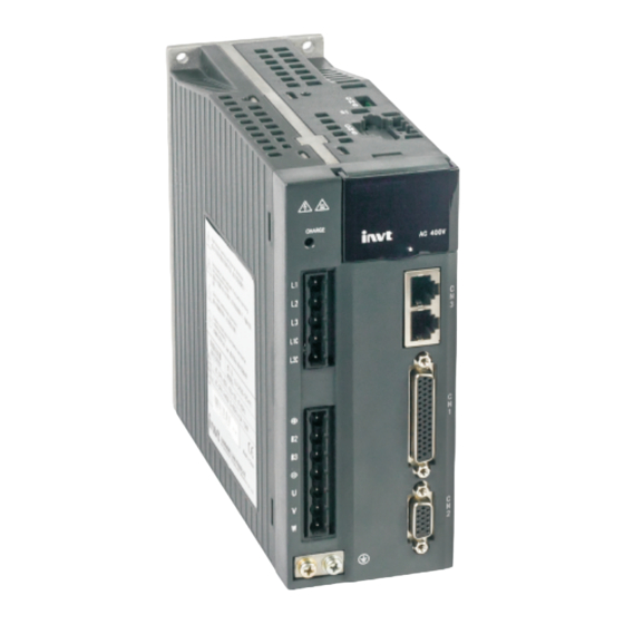
Page 4: Hardware Configuration
INVT SV-DA200 EtherCAT Technical Guide 1 Hardware configuration 1.1 Terminal wiring The EtherCAT communication card of SV-DA200 servo drive adopts external connection mode. The front view of the communication card is shown as below. CN3 terminal is the connection terminal of EtherCAT. -
Page 5: Cn1 Terminal Definition And Wiring
INVT SV-DA200 EtherCAT Technical Guide 1.3 CN1 Terminal Definition and Wiring The IO of the DA200 EtherCAT type is different from the standard type, the pin of the medium power range (7.5kW~22kW) CN1 terminal (DB44) is defined as follows (red font for the difference to the standard type), the CN1 terminal pin 1 of the small power range (0.1kW~5.5kW) of the EtherCAT type is... - Page 6 INVT SV-DA200 EtherCAT Technical Guide EtherCAT type have 3 analog inputs (AD1 is a 16 bit analog input, however, the small power range does not have this input, so the pin 1 of the CN1 is reversed); 2 analog outputs; 7 adigital inputs; 4 4 groups of differential adigital output.
- Page 7 INVT SV-DA200 EtherCAT Technical Guide also connect as follows: ...
-
Page 8: Software Configuration
INVT SV-DA200 EtherCAT Technical Guide 2 Software configuration 2.1 Basic setup of EtherCAT application It is necessary to configure the following parameters before conducting EtherCAT application with SV-DA200 servo drive: Set P0.03[control mode] to 8 [EtherCAT mode] via LED panel or ServoPlorer;... -
Page 9: Ethercat Communication
INVT SV-DA200 EtherCAT Technical Guide position command smoothing effect can be achieved by adding position command forecast function if one or multiple cycle position command are lost, with precondition that P4.26 is set properly. If it is set to non-zero, compensation will be made based on previous position increment when position command loss occurred, and the compensation cycle is equal to the value defined with P4.27;... -
Page 10: Ethercat Slave Information
EtherCAT slave information file (xml file) is used for master reading and building the configuration between master and slave. XML file contains information required by EtherCAT communication setup. INVT provides “INVT_DA200_CoE.xml” file for DA200 drive. 2.2.3 EtherCAT state machine EtherCAT state machine is used to describe the state and state change of slave application. The request of state change is usually initiated by master and responded by slave. -
Page 11: Pdo Process Data Mapping
INVT SV-DA200 EtherCAT Technical Guide State Description Slave determines whether mail is initialized normally Pre-Operation Mail communication is activated (Pre-Op) Process data (PDO) communication is unavailable Master is process data configuration sync manager channel and FMMU channel ... -
Page 12: Network Synchronization Based On Distributed Clock
INVT SV-DA200 EtherCAT Technical Guide PDO distribution: In order to realize process data interaction of EtherCAT communication, it is necessary to distribute PDOs to Sync Manager; Sync Manager PDO distributes objects (Sync Manager PDO Assign objects: 0x1C12, 0x1C13) to establish the relationship between PDOs and Sync Manager, as shown below. -
Page 13: Emergency Messages
INVT SV-DA200 EtherCAT Technical Guide DC mode (ESC register: 0x980 = 0x0300, P4.08 = 2 ) In this mode, local application program is sync with Sync0 time. Note: ESC is the abbreviation of EtherCAT Slave Controller Index Sub... -
Page 14: Compatible Communication Protocol
INVT SV-DA200 EtherCAT Technical Guide 2.3 Compatible communication protocol Applicable IEC 61158 Type12, IEC 61800-7 CiA402 Drive communication Profile standard Physical layer 100BASE-TX (IEEE802.3 ) CN7 (RJ45 ) : EtherCAT Signal IN Bus connection CN8 (RJ45 ) : EtherCAT Signal OUT... -
Page 15: Cia402 Device Protocol
INVT SV-DA200 EtherCAT Technical Guide 3 CiA402 device protocol The master controls DA200 servo drive via Controlword (control word, 0x6040) and acquires present drive status by reading Statusword (status word, 0x6041). The servo drive achieves motor control function according to master control commands. -
Page 16: Detail Of Status Word (0X6041)
INVT SV-DA200 EtherCAT Technical Guide Introduction to each 6040 bit: Among which: MSB: Most Significant Bit; LSB: Least Significant Bit; O: Optional; M; Mandatory BITS 0 - 3 AND 7 (bits used for status control); Among which: X is irrelevant;... -
Page 17: Profile Position Mode
INVT SV-DA200 EtherCAT Technical Guide Description M / O Warning Manufacture specific Remote Target reached Internal limit active 12 – 13 Operation mode specific 14 – 15 Manufacturer specific BIT 0 – 3, 5, AND 6: Value (binary) State xxxx xxxx x0xx 0000... -
Page 18: Other Objects
INVT SV-DA200 EtherCAT Technical Guide Set [6083 : Profile acceleration] as scheduled speed (the unit is relative to P4.25 ); Note: Under this mode, both 6083 and 6084 correspond to P5.37 in the drive (in user unit); Set [607A : Target position] as target position (unit: user unit); correspond to P6.01 in the drive;... -
Page 19: Control Word (0X6040) Of Profile Position Mode
INVT SV-DA200 EtherCAT Technical Guide Index Name Type Attr. 6065 Following error window UNSIGNED32 6067 Position window UNSIGNED32 607A Target position INTEGER32 6081 Profile speed UNSIGNED32 6083 Profile acceleration UNSIGNED32 6093 Position factor UNSIGNED32 60F4 Following error actual value INTEGER32 Note: For detailed description of each object, see CiADS402. - Page 20 INVT SV-DA200 EtherCAT Technical Guide a) Single set-point: Diagram of single set-point The following steps are necessary if the target position transmitted is increment mode: 1): Set 6040h to 0x4F (in which bit6 is to set increment mode, bit3~bit0 is to enable drive);...
-
Page 21: Cyclic Synchronous Position Mode
INVT SV-DA200 EtherCAT Technical Guide 3.3 Cyclic Synchronous Position Mode 3.3.1 Basic description The theory of cyclic synchronous position mode is similar to that of position interpolation mode. Interpolation of position command is achieved by the master while the master also offers additional speed feedforward commands and torque feedforward commands. -
Page 22: Mode-Related Objects List
INVT SV-DA200 EtherCAT Technical Guide Set [6040 : Control word] to enable servo drive, Homing operation starts (Bit4 ) from the change of 0->1 and interrupts homing process from the change of 1->0. Motor searches for limit switch and Home switch to complete Homing action;... - Page 23 INVT SV-DA200 EtherCAT Technical Guide Homing Start Target Reference Homing mode directio positio point mode Detailed introduction (DS402) position (P5.10) then returns at low speed and searches for target zero position (the first encoder Z pulse position after leaving NOT) after reaching NOT.
-
Page 24: Profile Speed Mode
INVT SV-DA200 EtherCAT Technical Guide 3.5 Profile Speed Mode 3.5.1 Basic description Under Profile speed mode, the drive receives the speed command sent by the master and conducts speed planning according to the acceleration planning parameters. 3.5.2 Operation mode 1. Set [6060 : Mode of operations] to 3 (Profile speed mode);... -
Page 25: Other Objects
INVT SV-DA200 EtherCAT Technical Guide P4.13 of the drive; 6. Check [6041 : Status word] to acquire status feedback of the servo motor (Speed zero, Max slippage error, Target reached, Internal limit active); 3.6.3 Other objects Check [606C : Speed actual value] to acquire actual speed feedback (the unit is related to P4.25);... -
Page 26: Application Examples
INVT SV-DA200 EtherCAT Technical Guide Index Name Type Attr. 6060 Modes of operation INTEGER8 6061 Modes of operation display INTEGER8 6071 Target torque INTEGER16 6072 Max torque UNSIGNED16 6073 Max current UNSIGNED16 6075 Motor rated current UNSIGNED32 6076 Motor rated torque... -
Page 27: Mode-Related Objects List
INVT SV-DA200 EtherCAT Technical Guide 3.8.2 Mode-related objects list Index Name Type Attr. 60B8 Touch Probe Control word UNSIGNED16 60B9 Touch Probe Status word UNSIGNED16 60BA Probe 1 positive edge value (Encoder zero signal) INTEGER32 60BB Probe 2 positive edge value (Encoder zero signal) INTEGER32 3.8.3 Description of control word &... -
Page 28: Object Dictionary
INVT SV-DA200 EtherCAT Technical Guide 4 Object dictionary 4.1 Object specification 4.1.1 Object type Object Definition name Individual variable value eg UNSIGNED8, Boolean, float, INTEGER16, etc. An array of multiple data constituted by basic variables of the same type. ARRAY Sub-index 0 is UNSIGNED8 type which indicates the number of data in the array. -
Page 29: Overview Of Object Group 2000 4000
INVT SV-DA200 EtherCAT Technical Guide Index Object Type Name Data Type Access Mappable 6064 Position actual value INTEGER32 6065 Following error window UNSIGNED32 6066 Following error time out UNSIGNED16 606C Speed actual value INTEGER32 6071 Target torque INTEGER16 6072 Max torque... -
Page 30: Drive Parameters
INVT SV-DA200 EtherCAT Technical Guide 3019 number of multi turns, corresponding to R0.25. The following two parameters will store the capture value only when P4.25 is set to factory unit. 3020 Encoder Feedback Cap value, it is used to store the encoder position during touch probe1 capture. -
Page 31: Fault And Diagnosis
INVT SV-DA200 EtherCAT Technical Guide 5 Fault and diagnosis 5.1 EtherCAT communication faults and remedies Fault code Fault name Fault cause Solution EtherCAT fault – Poor contact of EtherCAT Er24-8 Replace the servo initialization fault chip Download xml file to EtherCAT EtherCAT fault –... - Page 32 INVT SV-DA200 EtherCAT Technical Guide Fault code Fault name Fault cause Solution Encoder signal cable U, V, W, A, B and Replace the encoder cable if fault-encoder Z phase is disconnected; cable is disconnected. Er02-1 feedback error is 4. Encoder A/B phase 2.
- Page 33 INVT SV-DA200 EtherCAT Technical Guide Fault code Fault name Fault cause Solution data to encoder EEPROM. constantly, replace the motor. 1. Select present motor model via P0.00, then execute encoder For the motor equipped with EEPROM parameter write Encoder fault-no communication encoder, operation via P4.97;...
- Page 34 INVT SV-DA200 EtherCAT Technical Guide Fault code Fault name Fault cause Solution software limit) Setting P5.10 sub-mode setting is Set P5.10 correctly based on Er05-4 fault-homing wrong detailed parameter instructions. mode setting fault Setting Single travel should not exceed fault-jogging...
- Page 35 INVT SV-DA200 EtherCAT Technical Guide Fault code Fault name Fault cause Solution This fault occurred when Hardware 1. Remove external fault input, digital terminal configured as Er10-3 fault-external enable fault clearance. external fault input function input fault 2. Re-power on the drive.
- Page 36 INVT SV-DA200 EtherCAT Technical Guide Fault code Fault name Fault cause Solution detection circuit of the drive is enabled, if it is abnormal and damaged. does not match the grid input voltage, replace the drive. 1. Detect whether grid input...
- Page 37 INVT SV-DA200 EtherCAT Technical Guide Fault code Fault name Fault cause Solution is wrong P4.41 are set improperly. In non-torque mode, the deviation between motor 1. Check motor cable phase speed and speed command sequence and ensure the wiring exceeds the value defined is correct.
-
Page 38: Give Instructions Without Action
INVT SV-DA200 EtherCAT Technical Guide Fault code Fault name Fault cause Solution Position command’s single 1. Reduce the single variation Position gain variation quantity after quantity of position command; Er22-2 overflow fault converted by electric gear 2. Modify electric gear ratio to ratio exceeds 2 appropriate range. -
Page 39: Reference
INVT SV-DA200 EtherCAT Technical Guide 6 Reference 1. Hardware Data Sheet ET1100 EtherCAT Slave Controller V1.8. May 3 2010; 2. Xunji and Liu yanqiang. Design and Application of Industrial Ethernet Fieldbus EtherCAT Drive Program (1 ed.). Beihang University Press. March 2010;...
Need help?
Do you have a question about the SV-DA200 Series and is the answer not in the manual?
Questions and answers