INVT SV-DA200 Series Operation Manual
Ac servo drive
Hide thumbs
Also See for SV-DA200 Series:
- Operation manual (286 pages) ,
- Technical manual (45 pages) ,
- Technical manual (31 pages)
Table of Contents
Advertisement
Advertisement
Table of Contents

Related Manuals for INVT SV-DA200 Series


Summary of Contents for INVT SV-DA200 Series
- Page 1 Series AC ser vo drive INVT INDUSTRIAL TECHNOLOGY (SHANGHAI) CO.,LTD.
- Page 2 SV-DA200 series AC servo drive Preface Preface Thanks for selecting SV-DA200 servo drive. SV-DA200 servo drive series products adopt modular design with abundant functions and powerful performance. The upper PC software uses USB communication and the bus control is optional among Modbus bus, CANopen bus, EtherCAT bus, MotionNet bus and the PROFIBUS-DP bus which can be selected via extension card.
- Page 3 SV-DA200 series AC servo drive Safety precautions Safety precautions Safety symbols: The safety symbols are marked in the front or side of the servo drive. Users must follow these safety instructions when operating on the servo drive. Recycling symbol: When the life cycle ends, the product should enter the recycling system. Dispose of it separately at an appropriate collection point instead of placing it in the normal waste stream.
- Page 4 SV-DA200 series AC servo drive Safety precautions related to electricity) to the enclosure or short connect the external cables, otherwise electric shock or short circuit may occur. Rewire the drive after 15 minutes when disconnecting the power supply, otherwise electric shock may occur.
-
Page 5: Table Of Contents
SV-DA200 series AC servo drive Product overview Content Preface ............................I Safety precautions ......................... II Content ............................1 1 Product overview ........................3 1.1 Servo drive ........................... 3 1.2 Servo motor ........................10 1.3 Cables ..........................12 1.4 Braking resistor specification ....................16 2 Installation instruction ...................... -
Page 6: Table Of Contents
SV-DA200 series AC servo drive Product overview 5.2 Display and operation ......................83 6 Function codes ......................... 90 6.1 Basic control (P0 group parameters) ................... 90 6.2 Autotuning control parameters (P1) ................... 113 6.3 Motor control parameters (P2)................... 119 6.4 I/O management parameters (P3) ..................133 6.5 Extension and application (P4) .................. -
Page 7: Product Overview
SV-DA200 series AC servo drive Product overview 1 Product overview 1.1 Servo drive 1.1.1 Instruction to the drive DA200 series servo drive (100W–55kW) Specification Description 220V system input voltage 1P/3P AC220V(-15%)–240V(+10%) 47Hz–63Hz Power supply 400V system input voltage 3P AC380V(-15%)–440V(+10%) 47Hz–63Hz 10 inputs for standard type, pulse type and CANopen bus type;... - Page 8 SV-DA200 series AC servo drive Product overview DA200 series servo drive (100W–55kW) Specification Description 1. Retention pulse clearing; 2. Command pulse input disabled; Control input 3. Electronic gear ratio switching; 4. Vibration control switching, etc Control output Positioning completion output, etc Max.
- Page 9 SV-DA200 series AC servo drive Product overview DA200 series servo drive (100W–55kW) Specification Description Zero speed In the speed mode, it can set the operation mode as clamp the speed mode and position mode Speed command A delay filter of analog input speed command...
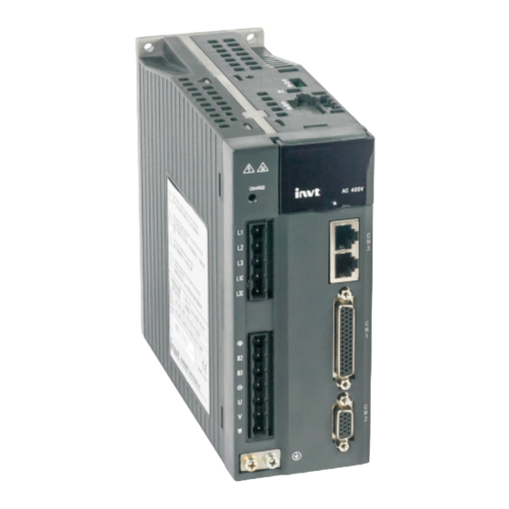
- Page 10 SV-DA200 series AC servo drive Product overview 1.1.2 External appearance of the drive Standard model S1: STO sele ction CN 5:2nd e ncode r a nd S TO CN 4:US B port of up per P C LED dis play...
- Page 11 SV-DA200 series AC servo drive Product overview 1.1.3 Naming of the drive SV-DA200-0R4-2-E0-XXXX ① ② ③ ④ ⑤ ⑥ ⑦ Symbol Instruction Naming instance ① Product category SV: Servo system product ② Product series DA200: Product series 0R1: 100W 0R2: 200W...
- Page 12 SV-DA200 series AC servo drive Product overview Function difference between different machine types: Small power range: 100W–5.5kW 16-bit Rotary PROFI Pulse RS48 Ether Motion Photoelectri Drive type Symbol analog transfor input encoder open c encoder input ○ ○ ○ ○...
- Page 13 SV-DA200 series AC servo drive Product overview 1.1.5 Power ratings and cabinet volumes Input Output Cabinet Model Rated current Power Rated volume Voltage (V) (kW) current (A) SV-DA200-0R1-2 Single/Three phase 220 0.9/0.4 SV-DA200-0R2-2 Single/Three phase 220 1.8/0.8 SV-DA200-0R4-2 Single/Three phase 220 3.6/1.5...
-
Page 14: Servo Motor
SV-DA200 series AC servo drive Product overview 1.2 Servo motor 1.2.1 Nameplate of the motor MODEL: SV-ML06-0R4G-2-4A0-3000 INPUT: AC 3PH 220V 2.8A OUTPUT(RATED): 400W 3000r/min 1.3N· m IP65 S1 CLASS F NO.3010004(236) Note: “No. 3010004” in the nameplate is the motor model code (motor code for short). Please input this code into servo parameter P0.00 correctly (P0.00 is long parameter which can be set via keypad. - Page 15 SV-DA200 series AC servo drive Product overview Symbol Instruction Naming instance 0R7: 750W 0R8: 800W/850W 1R0: 1.0kW 1R2: 1.2kW 1R3: 1.3kW 1R5: 1.5kW 1R8: 1.8kW 2R0: 2.0kW 3R0: 3.0kW 4R4: 4.4kW 5R5: 5.5kW 7R5: 7.5kW 011: 11kW 015: 15kW 022: 22kW...
-
Page 16: Cables
SV-DA200 series AC servo drive Product overview Remark: : 17-bit absolute single turn motor belongs to a separate series and its dimension and parameters are different. Only electromagnetic brake is used. Please pay attention to corresponding series when selecting models;... - Page 17 SV-DA200 series AC servo drive Product overview Symbol Instruction Naming instance 10R: 10mm 16R: 16mm 25R: 25mm 35R: 35mm 50R: 50mm 03: 3m 05: 5m ④ Cable length 10: 10m …… A: 4PIN plastic plug B: 4PIN regular aviation plug YD28 C: 4PIN metal plug ⑤...
- Page 18 SV-DA200 series AC servo drive Product overview Symbol Instruction Naming instance E: 4PIN regular aviation plug YD18 N: 4PIN regular aviation plug YD32 S: Copper tube terminal SC B: Euro 7PIN 20A plug ⑥ Plug on drive end W: No plug S: Copper tube terminal SC 1.3.4 Naming of the encoder cables...
- Page 19 SV-DA200 series AC servo drive Product overview 1.3.5 Naming of encoder cables fittings DBEL-AA ① ② ⑨ ⑤ Symbol Instruction Naming instance ① Product series For internal use by manufacturer ② Encoder cable EL: Encoder cable ⑨ Plug on drive end...
-
Page 20: Braking Resistor Specification
SV-DA200 series AC servo drive Product overview 1.4 Braking resistor specification Embedded braking Min. resistance of external Drive model resistor braking resistors 60Ω SV-DA200-0R1-2 60Ω SV-DA200-0R2-2 60Ω SV-DA200-0R4-2 30Ω 60W 30Ω SV-DA200-0R7-2 30Ω 60W 30Ω SV-DA200-1R0-2 30Ω 60W 20Ω SV-DA200-1R5-2 15Ω... -
Page 21: Installation Instruction
SV-DA200 series AC servo drive Installation instruction 2 Installation instruction 2.1 Drive dimension 2.1.1 A/B/C size and dimension diagram 2.1.2 Dimension diagram for D size -17-... - Page 22 SV-DA200 series AC servo drive Installation instruction 2.1.3 Dimension diagram for F/F2 size 2.1.4 Dimension diagram for G size 2.1.5 Dimension diagram for H size -18-...
- Page 23 SV-DA200 series AC servo drive Installation instruction 2.1.6 Detailed dimension table External dimension Installation dimension Installation Volume Model hole (mm) H(mm) W(mm) D(mm) A (mm) B1 (mm) B2 (mm) W1(mm) SV-DA200-0R1-2 M4(Φ5) SV-DA200-0R2-2 22.5 SV-DA200-0R4-2 SV-DA200-0R7-2 M4(Φ5) SV-DA200-1R0-2 SV-DA200-1R5-2 SV-DA200-2R0-2 M4(Φ5)
-
Page 24: Drive Installation
SV-DA200 series AC servo drive Installation instruction 2.2 Drive installation 2.2.1 Installation mode 1) Base installation (there is a Φ5 installation hole at the lower left corner and upper right corner of the rear board respectively) 2) Bracket installation (the installation bracket is optional) - Page 25 SV-DA200 series AC servo drive Installation instruction 2.2.2 Installation space and direction Please install the servo drive vertically and keep enough installation space for good ventilation. Install fans if necessary to ensure the temperature inside the control cabinet is lower than 45℃.
-
Page 26: Motor Dimension
SV-DA200 series AC servo drive Installation instruction 2.3 Motor dimension Note: As motor structure and dimension may vary slightly with design modification, for those who are sensitive to the installation length of motor, please confirm the installation length with our business staff before ordering. - Page 27 SV-DA200 series AC servo drive Installation instruction 2.3.2 Outline and installation dimension for 60 base (mm) 4-Φ5.5 M4 depth 10 Φ70 20.5 60.2 Motor model (2500-PPR/multi-turn absolute L(mm) value/rotary transformer) W/o brake Permanent magnet brake SV-ML06-0R2G-2-□A□ SV-ML06-0R4G-2-□A□ SV-MH06-0R4G-2-□A□ 4-Φ5.5 M5 depth 15 Φ70...
- Page 28 SV-DA200 series AC servo drive Installation instruction 2.3.3 Outline and installation dimension for 80 base (mm) 4-Φ6.3 Φ90 M5 depth 10 21.5 L(mm) Motor model (2500-PPR/multi-turn Permanent magnet Electromagnetic absolute value/rotary transformer) W/o brake brake brake SV-ML08-0R7G-2-□A□ SV-MH08-0R7G-2-□A□ 4-Φ6.3 Φ90 Φ19.5×2...
- Page 29 SV-DA200 series AC servo drive Installation instruction 2.3.4 Outline and installation dimension for 110 base (mm) 4-Φ9 M6 depth 20 Φ130 Φ20×2 21.5 L(mm) Motor model (2500-PPR/multi-turn Permanent magnet Electromagnetic absolute value/rotary transformer) W/o brake brake brake SV-MM11-0R8E-2-□A□ SV-MM11-1R2G-2-□A□ SV-MM11-1R5G-2-□A□...
- Page 30 SV-DA200 series AC servo drive Installation instruction 2.3.5 Outline and installation dimension for 130 base (mm) 4-Φ9 Φ24.4×2 M6 depth 22 Φ145 24.5 L(mm) Motor model (2500-PPR/multi-turn Permanent magnet Electromagnetic absolute value/rotary transformer) W/o brake brake brake SV-MM13-1R0E-□-□A□ SV-MM13-1R5E-□-□A□ SV-MM13-2R0E-□-□A□...
- Page 31 SV-DA200 series AC servo drive Installation instruction 2.3.6 Outline and installation dimension for 180 base (mm) Φ38.5×2.5 Φ200 M8 depth 25 4-Φ13.5 10h9 L(mm) Motor model (2500-PPR/multi-turn Permanent magnet Electromagnetic absolute value/rotary transformer) W/o brake brake brake SV-MM18-3R0B-□-□A□ SV-MM18-4R4B-□-□A□ SV-MM18-5R5B-4-□A□...
- Page 32 SV-DA200 series AC servo drive Installation instruction 2.3.7 Outline and installation dimension for 200 base (mm) 12h9 M10 depth 30 4-Φ13.5 Φ42 Φ215 200×200 16.5 221×221 L(mm) Motor model (2500-PPR/multi-turn Permanent magnet Electromagnetic absolute value/rotary transformer) W/o brake brake brake SV-MH20-011B-4-□A□...
-
Page 33: Motor Installation
SV-DA200 series AC servo drive Installation instruction 2.4 Motor installation ◆ Do not pull the motor leads or output shaft during fetching and moving the motor; ◆ Do not beat or hammer during the motor assembly to avoid damage to the encoder or shafts;... - Page 34 SV-DA200 series AC servo drive Installation instruction Motor model Max. Max. Rotation inertia Weight Rated Rated Rated Rated Max. (2500-PPR/multi- turn transient transient standard/ with Voltage standard/ power current torque speed speed absolute/ rotary current torque brake with brake (kW)
- Page 35 SV-DA200 series AC servo drive Installation instruction 2.5.2 Motor specification (17-bit single-turn absolute value) Rotational Max. Max. Weight Motor model Rated Rated Rated Rated Max. inertia transien transient Voltage standard/ (17-bit single-turn absolute power current torque speed speed standard/with t current...
-
Page 36: Wiring Instruction
SV-DA200 series AC servo drive Wiring instruction 3 Wiring instruction 3.1 System wiring Power L1 L 2 L3 Breaker Use d to cu t o ff th e circu it wh e n p o w e r ca b le flo w s... - Page 37 SV-DA200 series AC servo drive Wiring instruction 3.1.1 Requirements on input power cable The dimension of input power cable shall comply with local regulations. The input power cable must be able to withstand corresponding load current. The max rated temperature margin of input power cable should not be lower than 70℃ under continuous operation.
- Page 38 SV-DA200 series AC servo drive Wiring instruction 3.1.3 Cable diameter of main circuit Small power range (100W–5.5kW) main circuit cable diameter table Recommended cable Connectable cable Terminal Tightening diameter (mm diameter (mm Drive model screw torque L1\L2\L3 L1\L2\L3 (+), B2,...
- Page 39 SV-DA200 series AC servo drive Wiring instruction 3.1.4 EMI filter Drive model EMI filter model SV-DA200-0R1-2 SV-DA200-0R2-2 SV-DA200-0R4-2 FLT-P04006L-B SV-DA200-0R7-2 SV-DA200-1R0-4 SV-DA200-1R5-4 SV-DA200-1R0-2 SV-DA200-1R5-2 SV-DA200-2R0-4 FLT-P04016L-B SV-DA200-3R0-4 SV-DA200-2R0-2 SV-DA200-3R0-2 SV-DA200-4R4-4 FLT-P04032L-B SV-DA200-4R4-4 SV-DA200-5R5-4 SV-DA200-7R5-4 FLT-P04045L-B SV-DA200-011-4 SV-DA200-015-4 FLT-P04065L-B SV-DA200-022-4 FLT-P04100L-B...
-
Page 40: Terminal Wiring Of The Main Circuit
SV-DA200 series AC servo drive Wiring instruction 3.2 Terminal wiring of the main circuit 3.2.1 Wiring diagram of single phase 220V (small power range: 100W–5.5kW) · The user is required to make this emergency stop protection circuit. · Add surge absorbing devices on both ends of the electromagnetic contactor winding. - Page 41 SV-DA200 series AC servo drive Wiring instruction 3.2.2 Wiring diagram of three phase 220V/400V (small power range: 100W–5.5kW) · The user is required to make this emergency stop protection circuit. · Add surge absorbing devices on both ends of the electromagnetic contactor winding.
- Page 42 SV-DA200 series AC servo drive Wiring instruction 3.2.3 Wiring diagram of three phase 400V (medium power range: 7.5kW–55kW) · The user is required to make this emergency stop protection circuit. · Add surge absorbing devices on both ends of the electromagnetic contactor winding.
-
Page 43: Wiring Of Motor Power Cables
SV-DA200 series AC servo drive Wiring instruction 3.3 Wiring of motor power cables 3.3.1 2500-PPR 40/60/80-base 100W–750W motor power cable A direction view Wiring relation Definition Core wire color X1.7 X2.3 Brown X1.6 X2.1 X1.5 X2.2 Blue Ground terminal X2.4 Yellow/green X1.4... - Page 44 SV-DA200 series AC servo drive Wiring instruction Wiring relation Definition Core wire color X1.7 X2.4 Brown X1.6 X2.3 X1.5 X2.2 Blue Ground terminal X2.1 Yellow/green X1.4 X1.3 Short connect to X1.2 X1.2 Short connect to X1.3 X1.1 3.3.4 130/180-base 2kW–4.4kW (220V) and 4.4kW–7.5kW (380V) motor power cable (except for...
-
Page 45: Control I/O-Cn1 Terminal Layout
SV-DA200 series AC servo drive Wiring instruction 3.4 Control I/O-CN1 terminal layout CN1 plug pin layout DO2 DO1 DO6 - DO3 DI3 DO5 GND AD3 GND GND DI8 OCB DO4 OZ+ OZ- OCZ AO2 + DI10 AO1 AD2 GND DI9... - Page 46 SV-DA200 series AC servo drive Wiring instruction 3.5.2 2500-PPR 40, 60, 80-base encoder cable A dire ction v iew B dire ction v iew Wiring relation Signal Core wire structure X1.1 X2.1 Twisted pair X1.7 X2.7 X1.2 X2.2 Twisted pair X1.8...
- Page 47 SV-DA200 series AC servo drive Wiring instruction 3.5.4 17-bit and 23-bit 40, 60, 80 base encoder cable B dir ec tion v iew A dire ction v iew Wiring relation Signal Core wire structure X1.1 X2.1 Twisted pair X1.7 X2.2 X1.5...
-
Page 48: Wiring Of 485/Can-Cn3 Terminals
SV-DA200 series AC servo drive Wiring instruction 3.6 Wiring of 485/CAN-CN3 terminals Pin8 Pin1 CN3 terminal function Remark Name Function GND_CAN CAN chip power GND GND_485 485 chip power GND 485 and CAN use the RS485+ RS485 data + same interface and each... - Page 49 SV-DA200 series AC servo drive Wiring instruction 3.8 2 encoder and STO-CN5 terminal wiring 3.8.1 Terminal interface and definition of small power range (100W–5.5kW) Small power range CN5 port function Name Function Remark HWBB1+ Safety input 1+ HWBB2+ Safety input 2+...
-
Page 50: Wiring Of Profibus-Dp Terminals
SV-DA200 series AC servo drive Wiring instruction CN5 terminal function table Remark Pin no. Name Function EXB+ Linear encoder encoder) B+ or 2 encoder EXB- Linear encoder encoder) B- EXZ+ Linear encoder encoder) Z+ EXZ- Linear encoder encoder) Z- 7, 9... - Page 51 SV-DA200 series AC servo drive Wiring instruction 3.10 Wiring of motor temperature resistor-CN7 terminal in medium power range (7.5kW–55kW) Function of CN7 port Pin no. Name Function Remark KTY84-1 Support KTY84 only KTY84-2 Note: The motor temperature sampling function is turned off by default. Set P4.45 [Temperature protection threshold of medium-power motor] to a non-zero value.
-
Page 52: Control Mode Applications
SV-DA200 series AC servo drive Control mode applications 4 Control mode applications 4.1 Standard wiring of the position mode -48-... -
Page 53: Standard Wiring Of The Speed Mode
SV-DA200 series AC servo drive Control mode applications 4.2 Standard wiring of the speed mode -49-... -
Page 54: Standard Wiring Of The Torque Mode
SV-DA200 series AC servo drive Control mode applications 4.3 Standard wiring of the torque mode -50-... -
Page 55: Cn1 Function Instruction
SV-DA200 series AC servo drive Control mode applications 4.4 CN1 function instruction 4.4.1 Pins of CN1 terminal CN1 plug pin layout DO6 COM- DO3 DO5 GND GND GND DI7 COM+ OCB DO4 + DI10 PULS PULS OCA GND DI5 SIGN- SIGN+ OCS CN1 plug signal layout 4.4.2 Definition of CN1 terminals... - Page 56 SV-DA200 series AC servo drive Control mode applications 4.4.3 Power supply signal Sign Pin no. Name Function COM- is the ground terminal of the 24V power. Its capacity Internal 24V is 100mA. If the actual load is higher than this value, the power supply user shall provide the power supply by themselves.
- Page 57 SV-DA200 series AC servo drive Control mode applications Position mode Speed mode Symbol Name Default Default Mark Function name Mark Function name value value Command pulse DI10 22 Digital input 10 0x008 0x006 Gain switching disabled Servo ready Servo ready...
- Page 58 SV-DA200 series AC servo drive Control mode applications Torque mode MotionNet mode Symbol Name Default Default Mark Function name Mark Function name value value 11 Digital output 3 0x010 TRCH Torque reaching 0x003 Fault output Speed zero Positioning 29 Digital output 4 0x00D...
- Page 59 SV-DA200 series AC servo drive Control mode applications Signal name Sign Function number Available mode Retention pulse clearing 0x07 This function is the control signal of retention pulse clearing and the detailed operation is relative to the setting of P3.45.
- Page 60 SV-DA200 series AC servo drive Control mode applications Signal name Sign Function number Available mode Speed command sign S-SIGN 0x0E This function is the sign selection of speed command input in the speed control mode. If P0.41 is 1, the input function is valid, and when the setting is 0, the function is invalid.
- Page 61 SV-DA200 series AC servo drive Control mode applications If the digital input is valid, the drive will report Er10-3 and stop. Signal name Sign Function number Available mode Inertia ratio switching 0x15 This function is the control signal of inertia ratio switching between 1 inertia ratio and 2 inertia ratio.
- Page 62 SV-DA200 series AC servo drive Control mode applications Signal name Sign Function number Available mode Vibration control switching input VS-SEL 0x1C The function is the control signal of 1 and 2 vibration control frequency. When the digital input is valid, the internal software uses P1.38; when invalid, use P1.36.
- Page 63 SV-DA200 series AC servo drive Control mode applications Signal name Sign Function number Available mode Gantry synchronization input clear 0x2D When this digital input is valid, gantry synchronous is removed. Signal name Sign Function number Available mode Master gantry synchronization alignment...
- Page 64 SV-DA200 series AC servo drive Control mode applications 4.4.4.2 Digital output instruction: Signal name Sign Function number Available mode Servo ready output 0x01 This function is the state signal of the drive. When valid, the drive can be enabled and provide power to the motor and when invalid, the drive gives no response to the command.
- Page 65 SV-DA200 series AC servo drive Control mode applications Signal name Sign Function number Available mode Speed reaching 0x0A The function is the state signal of output speed reaching. When it is valid, the current speed feedback is in the setting value of P3.54.
- Page 66 SV-DA200 series AC servo drive Control mode applications Signal name Sign Function number Available mode PTP output 2 PTPO2 0x18 This function is output PTP output 2 signal. Signal name Sign Function number Available mode PTP output 3 PTPO3 0x19 This function is output PTP output 3 signal.
- Page 67 SV-DA200 series AC servo drive Control mode applications 4.4.6 Analog input signals and functions Defaul Function Sign Pin no. Name Function t value name Precision of AD1 is 16-bit and precision Analog input 1 0x00 Invalid of AD2 and AD3 is 12-bit.
-
Page 68: Cn1 Wiring Instruction
SV-DA200 series AC servo drive Control mode applications 4.5 CN1 wiring instruction 4.5.1 Wiring of digital input circuit Connection diagram when the power supply is provided by user: 40 24V 40 24V DC12~24V DC12~24V 2 COM+ 2 COM+ 16 DI1... - Page 69 SV-DA200 series AC servo drive Control mode applications 4.5.2 Wiring of the pulse input circuit Connect mode 1: Differential mode Shielded Twisted cable pair PULS+ PULS PULS- SIGN+ SIGN SIGN- Control module side Drive side The maximum frequency of input pulse is 4MHz and the input signal voltage is ± 5V;...
- Page 70 SV-DA200 series AC servo drive Control mode applications European PLC is PNP module. Connection mode 3: Open collector mode 2 The control module is NPN (common cathode): Shielded Twisted cable pair 23 PULS+ PULS 24 PULS- 32 SIGN+ SIGN 33 SIGN-...
- Page 71 SV-DA200 series AC servo drive Control mode applications 4.5.3 Wiring of the analog input circuit 1 AD1 5 GND Twisted pair 20 AD2 19 GND Please connect shielded cable according to the device requirement Control module side Drive side ...
- Page 72 SV-DA200 series AC servo drive Control mode applications When inductive loads such as relay coil are connected, a free wheel diode must be fitted as shown in the figure; when optical coupler is connected, current limit resistor must be connected, otherwise the drive will be damaged.
- Page 73 SV-DA200 series AC servo drive Control mode applications 4.5.6 Wiring of the analog output circuit Measuring instruments or Servo drive external circuit Shield cable Twisted pair GND 5 GND 5 Connect the shield cable according to the requirement There are two analog output circuits in all. The output voltage range is -10V–10V. The Max output current is 3mA.
-
Page 74: Cn5 Wiring Diagram
SV-DA200 series AC servo drive Control mode applications 4.6 CN5 wiring diagram 4.6.1 CN5 wiring diagram of small power range (100W–5.5kW) encoder and STO ① Safety terminal signal is active-high ① Safety output signal is active-high EDM+ HWBB1+ HWBB1- EDM- HWBB2+ S1:STO switch... - Page 75 SV-DA200 series AC servo drive Control mode applications 4.6.2 CN5 wiring diagram of medium power range (7.5kW–55kW) encoder and STO ①24V power, built-in current limit resistor ① Safety terminal signal is active-high ① Safety output signal is active-high OC_EXA 19...
- Page 76 SV-DA200 series AC servo drive Control mode applications Control module is NPN type (common cathode): Shielded cable Twisted pair OC_EXA EXA- OC_EXB EXB- OC_EXZ EXZ- DC24V Control module side Drive side Control module is PNP type (common anode): DC24V - Shielded cable Twisted pair...
- Page 77 SV-DA200 series AC servo drive Control mode applications Control module is NPN type (common cathode): Shielded Twisted cable pair EXA+ EXA- EXB+ EXB- EXZ+ EXZ- Control module DC12~24V side Drive side Control mode is PNP type (common cathode): DC12~24V Shielded...
-
Page 78: Running And Operation
SV-DA200 series AC servo drive Running and operation 5 Running and operation 5.1 Running 5.1.1 First powering on Please check following items before power on: 1) Wiring The power supply of the servo drive (L1, L2, L3, L1C, L2C or R, S and T) should be connect to proper techniques;... - Page 79 SV-DA200 series AC servo drive Running and operation 5.1.1.2 Checking after powering-on After switching on both of the control circuit and main circuit power supplies, if the power supply is OK, the LED indicator will display 0 first and then display 8. If there is no fault alarm of the servo drive, the LED on the front panel displays the current speed of the servo motor as default.
- Page 80 SV-DA200 series AC servo drive Running and operation Steps: Complete the connection between the drive and the servo motor. Set P0.03 to “0”, the position control mode. Confirm the pulse output of the upper controller and adjust P0.23. Keep the pulse type the same with that of the upper controller.
- Page 81 SV-DA200 series AC servo drive Running and operation COM-. Then the servo enters into the locking state. The motor shaft may rotate at a low speed if there is no upper command voltage. It is necessary to adjust P3.20. Please refer to the detailed instruction of P3.20.
- Page 82 SV-DA200 series AC servo drive Running and operation of these parameters need to be set according to the site application demand. For examples, pulse input mode, electronic gear, frequency division coefficient of encoder output, upper/lower limit of analog input, etc. Some of these parameters need to be set according to the site debugging. For example, the parameters of the regulator loop which affect the system performance and other similar parameters.
- Page 83 SV-DA200 series AC servo drive Running and operation the stopping method through setting parameter P4.30. See description of P4.30 for details. This process will not cause regenerative braking. When a fault alarm occurs, the servo motor will stop. Select the stopping method of the servo motor when an alarm occurs through setting parameter P4.30.
- Page 84 SV-DA200 series AC servo drive Running and operation 5.1.9 Sequence diagram 5.1.9.1 Sequence diagram of power-on and servo ON Power-on process Servo On process Main power Main circuit power-on Control power Control circuit power-on About 1.2s Microprocessor state Program initialization...
- Page 85 SV-DA200 series AC servo drive Running and operation 5.1.9.2 Sequence diagram of power loss during running Main power Main circuit power loss Note 1 Control circuit power disconnection Control power PWM output Servo has output Servo has no output Servo ready output...
- Page 86 SV-DA200 series AC servo drive Running and operation 5.1.9.4 Servo OFF sequence in running state Servo enabling (SON) Enable Disabled Servo fault output No fault alarm (ALM) Servo ready output Valid (RDY) Dynamic brake Dynamic brake state Note 1 Dynamic brake switches on...
-
Page 87: Display And Operation
SV-DA200 series AC servo drive Running and operation 5.2 Display and operation 5.2.1 Display Keypad diagram: USB port Display MODE SET/ MODE key SET/SHIFT key UP key DOWN key LED display character (reference table): Corresponding Corresponding Corresponding Corresponding display display... - Page 88 SV-DA200 series AC servo drive Running and operation Button function table: Function MODE Used to switch between different modes or return to previous menu Used to select parameter upwards or increase value DOWN Used to select parameter downwards or decrease value Press for a long time =SET (about 0.6 seconds)
- Page 89 SV-DA200 series AC servo drive Running and operation 8. Setting of long parameters (corresponds to parameters with over 6 digits) in parameter area: SHIFT MODE DOWN SHIFT SHIFT DOWN SHIFT DOWN SHIFT SHIFT DOWN 5.2.2 State monitoring mode After power on, the screen will enter into “General monitoring mode”, display the parameters name for about 2.5 seconds and then display the current value.
- Page 90 SV-DA200 series AC servo drive Running and operation DOWN DOWN DOWN SHIFT MODE MODE SHIFT DOWN SHIFT DOWN 5.2.4 Parameter setting MODE key can be used to switch into the parameters setting mode. SHIFT key can be used to select the group number of the monitoring parameters, UP/DOWN can be used to select the internal parameter number and pressing for a long time, it can be used to select the parameter number quickly.
- Page 91 SV-DA200 series AC servo drive Running and operation Sign Name Jogging test Restore the factory parameter Program commissioning Analog input 1 zero drift clear Analog input 2 zero drift clear Analog input 3 zero drift clear Inertia identification Absolute value encoder clear Note: The auxiliary functions can be operated only when servo is disabled, otherwise users cannot enter the auxiliary function menu.
- Page 92 SV-DA200 series AC servo drive Running and operation 5.2.5.4 Operation flowchart of program commissioning Press MODE key to the auxiliary function mode. Press UP/DOWN key to the menu, and press SET key to the interface. The interface will display . In the interface of...
- Page 93 SV-DA200 series AC servo drive Running and operation 5.2.5.6 Operation flowchart of absolute encoder clear If the multi-turn encoders are used, the zeroing of mechanical system is needed after first power on. Press MODE key to switch to the auxiliary function mode. Press UP/DOWN key to the menu, and press SET key to the interface.
-
Page 94: Function Codes
SV-DA200 series AC servo drive Function codes 6 Function codes P-position mode; S-speed mode; T-torque mode. The definition of direction: From the angle of facing motor shaft, the counterclockwise direction is forward (CCW for short); clockwise (CW) is reverse; in terms of speed and torque reference value, positive value means position direction and negative value means negative direction. - Page 95 SV-DA200 series AC servo drive Function codes Setting range Default Unit Available mode P0.01 Encoder type 1–12 Generally, the system will set this parameter automatically after P0.00 is set correctly. In cases where encoder disconnection fault is reported during power up when motor is connected correctly, please check whether the drive supports motor encoder type, refer to chapter 1.1.3.
- Page 96 SV-DA200 series AC servo drive Function codes Setting range Default Unit Available mode P0.03 Control mode selection 0–9 This parameter can be used to set the operating mode of the system: Setting working working Instruction value mode mode Position mode: Control the angular displacement of servo motor via internal/external position command, thus achieving controlling over mechanical motion displacement.
- Page 97 SV-DA200 series AC servo drive Function codes be switched with control mode switching terminal Speed mode Torque mode Speed mode Mode switching signal (MCH) Motor speed Load torque Torque command Note: The switching mode is not limited by actual operation.
- Page 98 SV-DA200 series AC servo drive Function codes Setting range Default Unit Available mode P0.05 JOG speed 0–1000 r/min This parameter can be used to set the jog speed. For jogging, please refer to chapter 5.2.5.2 During jogging, the ACC/DEC time parameters (P0.54, P0.56, P0.55, and P0.57) are active. The motor will accelerate, decelerate, start and stop according to the settings.
- Page 99 SV-DA200 series AC servo drive Function codes Setting range Default Unit Available mode Reverse of frequency P0.08 division output 0–1 The reverse of B phase can be carried out through this parameter and the phase relation between A phase and B phase can be changed:...
- Page 100 SV-DA200 series AC servo drive Function codes Setting range Default Unit Available mode P0.10 Max. torque limit 1 0.0–500.0 300.0 Setting range Default Unit Available mode P0.11 Max. torque limit 2 0.0–500.0 300.0 These parameters can be used to set the maximum torque of the servo motor output. Taking the rated torque of the servo motor as 100%, the setting is the percentage of the rated torque of the servo motor.
- Page 101 SV-DA200 series AC servo drive Function codes Default monitoring Setting range Default Unit Available mode P0.15 parameters 0–22 This parameter is used to set the parameters which can be monitored while powering-on of the system: Setting value Parameter meaning Sign...
- Page 102 SV-DA200 series AC servo drive Function codes Parameter modification Setting range Default Unit Available mode P0.16 operation locked 0–1 This parameter is used to lock the parameter modification function (exclude P0.16 and parameters which cannot be saved after power off) to avoid mis-operation by users.
- Page 103 SV-DA200 series AC servo drive Function codes Pulse number per motor Setting range Default Unit Available mode P0.22 resolution 0–(2 10000 reference unit This parameter is used to set the number of pulses per motor resolution. Note: P0.22 is set to a non-zero value, the setting of P0.25–P0.29 is invalid. If 17-bit and 20-bit encoder is used, the more pulse number can be set for the higher precision.
- Page 104 SV-DA200 series AC servo drive Function codes Numerator of 1 Setting range Default Unit Available mode P0.25 electronic gear ratio 0–(2 Setting range Default Unit Available mode Denominator of the P0.26 electronic gear ratio 1–(2 10000 Setting range Default Unit...
- Page 105 SV-DA200 series AC servo drive Function codes select to adopt which parameter group to provide the electronic gear ratio through the digital input configured as electronic gear ratio selection function (SC1, SC2) on CN1, plug, the corresponding relation is shown below:...
- Page 106 SV-DA200 series AC servo drive Function codes reduce the mechanical shock when the input pulse commands frequency changes. It is shown as the figure below: Position before filtering Speed Position after filtering Position after filtering Time P0.34 P0.34 Note: If the parameter is modified during the operation, it will be valid after stopping.
- Page 107 SV-DA200 series AC servo drive Function codes Setting range Default Unit Available mode P0.38 Enable fully-closed loop 0–2 This parameter is used to enable the fully-closed loop function. When this parameter is set to 2, users can switch between fully-closed loop and semi-closed loop via the IO ports whose function code is 0x34 or 0x134.
- Page 108 SV-DA200 series AC servo drive Function codes Data size 16bit Data format P0.40 Modbus address 1080, 1081 CANopen address 0x2028, 0x00 Setting of speed Setting range Default Unit Available mode P0.41 command direction 0–1 This parameter is used to set the forward/reverse direction when P0.40 is 0 and 1 and the speed command sign is selected as S-SIGN.
- Page 109 SV-DA200 series AC servo drive Function codes Note: 1. This parameter is valid when P0.40 is set to “1”. 2. Set the parameter correctly after confirming the motor operation condition, if this parameter is set to a large value, the motor speed will fluctuate violently.
- Page 110 SV-DA200 series AC servo drive Function codes Control mode P0.40 Setting value SPD3 SPD2 SPD1 Parameters and setting value P0.46 internal speed 1 P0.47 internal speed 2 P0.48 internal speed 3 P0.49 internal speed 4 Speed mode P0.50 internal speed 5 P0.51 internal speed 6...
- Page 111 SV-DA200 series AC servo drive Function codes Example: If the reference speed is 2000r/min, the rated speed is 3000r/min and the ACC/DEC (P0.54, P0.55) time is set to 1500, then the actual ACC time t1 is 1500×(2000/3000)=1000ms and the DEC time t2 is 1500×(2000/3000)=1000ms. Please refer to the figure below:...
- Page 112 SV-DA200 series AC servo drive Function codes Data size 16bit Data format P0.57 Modbus address 1114, 1115 CANopen address 0x2039, 0x00 Setting range Default Unit Available mode P0.58 Zero speed clamp mode 0–3 This parameter is used to set the zero speed clamp mode.
- Page 113 SV-DA200 series AC servo drive Function codes Data size 16bit Data format P0.60 Modbus address 1120, 1121 CANopen address 0x203C, 0x00 Torque command Setting range Default Unit Available mode P0.61 direction setting 0–1 This parameter is used to select the torque command direction.
- Page 114 SV-DA200 series AC servo drive Function codes Setting range Default Unit Available mode P0.63 Analog input 2 reverse 0–1 Set the voltage polarity of analog input 2. Setting value Motor direction Positive polarity [+voltage]→[positive value],[- voltage]→[negative value] Negative polarity [+voltage]→[negative value],[- voltage]→[positive value]...
- Page 115 SV-DA200 series AC servo drive Function codes RAMP time of torque Setting range Default Unit Available mode P0.68 command 0–10000 This parameter is used to modify the planning curve when the torque command input changes, and it is the rising time from 0 to 100% of rated torque.
- Page 116 SV-DA200 series AC servo drive Function codes to position mode under position/speed, position/torque compound mode. Data size 16bit Data format P0.90 Modbus address 1180, 1181 CANopen address 0x205A, 0x00 Setting range Default Unit Available mode Positioning reference of P0.91 control mode switching -1–(2...
-
Page 117: Autotuning Control Parameters (P1)
SV-DA200 series AC servo drive Function codes 6.2 Autotuning control parameters (P1) 6.2.1 Inertia identification (Automatic gain) Setting range Default Unit Available mode Inertia online automatic P1.00 estimation 0–1 This parameter is used to set whether to adjust the inertia ratio and adjust the gain automatically. - Page 118 SV-DA200 series AC servo drive Function codes Inertia offline automatic Setting range Default Unit Available mode P1.04 estimation 0–1 The load inertial ratio of motor rotation inertia can be gained by setting this parameter. After setting the inertia identification, the motor will run 6 cycles to carry out the inertia identification. In each cycle, the motor will run at the mode of P1.05, the maximum rotation cycles are determined...
- Page 119 SV-DA200 series AC servo drive Function codes Speed level of inertia Setting range Default Unit Available mode P1.08 identification 0–3 This parameter is used to set the speed level of inertia identification. The larger the setting value, the faster the response and larger fluctuation of the presumption value.
- Page 120 SV-DA200 series AC servo drive Function codes notch filter→1 Copy the parameters of 3 notch filter to 1 notch filter and then notch filter restore the parameter of 3 notch filter to the default values notch filter→2 Copy the parameters of 4...
- Page 121 SV-DA200 series AC servo drive Function codes notch filter depth Setting range Default Unit Available mode P1.25 selection 0–100 This parameter is used to set the amplitude attenuation rate of 1 notch filter. When the setting value increases, the notch filter depth becomes shallow and phase lag will be smaller.
- Page 122 SV-DA200 series AC servo drive Function codes Refer to P1.23, P1.24 and P1.25 for detailed parameters setting. Data size 16bit Data format P1.32 Modbus address 1264, 1265 CANopen address 0x2120, 0x00 Data size 16bit Data format P1.33 Modbus address 1266, 1267...
-
Page 123: Motor Control Parameters (P2)
SV-DA200 series AC servo drive Function codes Data size 16bit Data format P1.38 Modbus address 1276, 1277 CANopen address 0x2126, 0x00 Data size 16bit Data format P1.39 Modbus address 1278, 1279 CANopen address 0x2127, 0x00 6.3 Motor control parameters (P2) 6.3.1 Gain setting... - Page 124 SV-DA200 series AC servo drive Function codes Setting range Default Unit Available mode P2.04 torque filter 0.00–25.00 0.84 This parameter is used to set the time constant of torque filter. Data size 16bit Data format P2.04 Modbus address 1408, 1409...
- Page 125 SV-DA200 series AC servo drive Function codes Speed feed-forward filter Setting range Default Unit Available mode P2.11 time 0.00–64.00 0.50 This parameter is used to set the speed feed-forward filter time. Data size 16bit Data format P2.11 Modbus address 1422, 1423...
- Page 126 SV-DA200 series AC servo drive Function codes 6.3.2 Gain switching Setting range Default Unit Available mode P2.20 gain setting 0–1 This parameter is used to set the right adjustment. Setting value Mode gain is fixed. Gain switching invalid→PI action Gain switching valid→P action Note: 0x006 is the digital input low level valid and the high level valid is 0x106.
- Page 127 SV-DA200 series AC servo drive Function codes fully-closed loop control. In the previous 1 gain, if the position command is not 0, it will switch With position to 2 gain. command In the previous 2 gain, if the 0 position command lasts in the delay time, it will return to 1 gain.
- Page 128 SV-DA200 series AC servo drive Function codes Note: Set the level<the delay, in the actual internal application, the delay=the level Data size 16bit Data format P2.25 Modbus address 1450, 1451 CANopen address 0x2219, 0x00 Setting range Default Unit Available mode Switching time of P2.26...
- Page 129 SV-DA200 series AC servo drive Function codes Delay time of speed Setting range Default Unit Available mode P2.28 control switching 0–10000 In the speed control, if set P2.27 to 3–5, when switching from 2 gain to 1 gain, it is the time from meeting the trigger conditions to the actual switching.
- Page 130 SV-DA200 series AC servo drive Function codes Setting range Default Unit Available mode Delay time of torque P2.32 control switching 0–10000 In torque control, if set P2.31 to 3, when switching from 2 gain to 1 gain, it is the time from meeting the trigger conditions to the actual switching.
- Page 131 SV-DA200 series AC servo drive Function codes Disturbance observer Setting range Default Unit Available mode P2.43 cut-off frequency 0–3000 This parameter is used to set the cut-off frequency of disturbance observer. Decreasing the set value can downgrade the noise; while increase the set value can reduce the delay of disturbance torque compensation, it is necessary to be used in combination with P2.42.
- Page 132 SV-DA200 series AC servo drive Function codes Determine whether the medium frequency vibration control is valid by setting this parameter. Set value Role Invalid Valid Data size Data format 16bit P2.53 Modbus address CANopen address 1506, 1507 0x2235, 0x00 Setting range...
- Page 133 SV-DA200 series AC servo drive Function codes Set the fine tuning of medium frequency vibration control filter time 2, which can be calculated automatically based on P2.54 [medium frequency vibration control frequency]. Users can carry out fine tuning via this parameter.
- Page 134 SV-DA200 series AC servo drive Function codes Setting range Default Unit Available mode P2.73 Friction compensation valid 0–1 Set whether friction compensation is valid by this parameter Setting value Function Invalid Friction compensation Data size 16bit Data format P2.73 Modbus address...
- Page 135 SV-DA200 series AC servo drive Function codes Data size 16bit Data format P2.78 Modbus address 1556, 1557 CANopen address 0x224E, 0x00 Setting range Default Unit Available mode P2.79 Reserved It is forbidden to modify this parameter. Data size 16bit Data format P2.79...
- Page 136 SV-DA200 series AC servo drive Function codes This parameter is used to set the torque feedforward selection. Set value Role Speed command feedforward Position command feedforward Data size Data format 16bit P2.85 Modbus address CANopen address 1570, 1571 0x2255, 0x00...
-
Page 137: I/O Management Parameters (P3)
SV-DA200 series AC servo drive Function codes Data size 16bit Data format P2.90 Modbus address 1580, 1581 CANopen address 0x225A, 0x00 6.4 I/O management parameters (P3) 6.4.1 Digital input/output Setting range Default Unit Available mode Input configuration of P3.00 digital input 1 0x000–0x136... - Page 138 SV-DA200 series AC servo drive Function codes Molecule 2 of electronic gear ratio 0x11A 0x01A PTP control trigger TRIG 0x11B 0x01B Vibration control switching input VS-SEL 0x11C 0x01C Fast stop Q-STOP 0x11D 0x01D PTP control stop PTP-ST 0x11E 0x01E Absolute position clearing...
- Page 139 SV-DA200 series AC servo drive Function codes Setting range Default Unit Available mode P3.01 Input configuration of digital 2 0x000–0x136 0x00D Setting range Default Unit Available mode P3.02 Input configuration of digital 3 0x000–0x136 0x004 Setting range Default Unit Available mode P3.03...
- Page 140 SV-DA200 series AC servo drive Function codes Setting range Default Unit Available mode P3.10 Output configuration of digital 1 0x000–0x11F 0x001 This parameter is used to select the configuration of the digital value 1 output function. It is a hex number.
- Page 141 SV-DA200 series AC servo drive Function codes Note: The default value is the function selection corresponds to position mode. Data size 16bit Data format P3.10 Modbus address 1620, 1621 CANopen address 0x230A, 0x00 Setting range Default Unit Available mode P3.11 Output configuration of digital 2 0x000–0x11F...
- Page 142 SV-DA200 series AC servo drive Function codes 6.4.2 Analog input / output adjustment Setting range Default Unit Available mode P3.20 Offset of analog input 1 -10.000–10.000 0.000 This parameter can be used to adjust the analog input 1 to improve the effective accuracy of the analog input.
- Page 143 SV-DA200 series AC servo drive Function codes Data size 16bit Data format P3.21 Modbus address 1642, 1643 CANopen address 0x2315, 0x00 Setting range Default Unit Available mode Voltage protection of P3.22 analog input 1 0.000–10.000 0.000 This parameter is used to set the overvoltage protection of analog input 1.
- Page 144 SV-DA200 series AC servo drive Function codes 1. The default value 0 means no overvoltage protection; 2. The input voltage should be no more than 10V, otherwise damage may occur to the drive. Data size 32bit Data format P3.25 Modbus address...
- Page 145 SV-DA200 series AC servo drive Function codes form. Setting value Definition Unit Invalid Motor speed r/min Speed of position command r/min Internal position command pulse(Encoder unit) Speed command r/min Torque command 0.1% Torque feedback 0.1% Command position deviation reference unit...
- Page 146 SV-DA200 series AC servo drive Function codes Speed (r/min) 3000r/min P3.31=300 1000r/min P3.31=100 10.00V AO1 output voltage (V) Note: 1. If the actual output speed is more than 3000r/min, AO1 output is 10V. Please select the gain according to the actual range of the parameter.
- Page 147 SV-DA200 series AC servo drive Function codes 6.4.3 Digital input / output settings Setting range Default Unit Available mode P3.40 Travel limit switch shield 0–2 This parameter is used to set whether the digital input configured as forward drive disabling (0x001 or 0x101) and reverse drive disabling (0x002 or 0x102) is valid or not.
- Page 148 SV-DA200 series AC servo drive Function codes Setting range Default Unit Available mode Command pulse input P3.44 invalid setting disabled 0–1 This parameter can set whether the digital input configured as command pulse disabling (0x008 or x0108) among P3.00–P3.09 is valid or not. If command pulse disabling function needs to be blocked, this parameter will do the trick.
- Page 149 SV-DA200 series AC servo drive Function codes Data size 16bit Data format P3.51 Modbus address 1702, 1703 CANopen address 0x2333, 0x00 Setting range Default Unit Available mode Hold time of position P3.52 arrival output terminal 0–30000 This parameter is used to set the hold time of position arrival output terminal.
- Page 150 SV-DA200 series AC servo drive Function codes Setting range Default Unit Available mode Locked time of servo after P3.56 braking 0–1000 This parameter is used to set the locked time of the servo after braking in the locked state. The servo is OFF in the locked state, the digital output state configured as BRK (0x005 or 0x105) is invalid.
- Page 151 SV-DA200 series AC servo drive Function codes Speed command * (r/min) Torque command 0.1% Speed compensation (r/min) Torque compensation 0.1% Negative-direction torque limit 0.1% Note: If P3.70 is 2 and P0.09 is 0 or 4, the analog input 3 corresponds to the positive torque limit internally and P0.62–P0.65, P3.23–P3.25 correspond to the negative torque limit internally.
- Page 152 SV-DA200 series AC servo drive Function codes This parameter is used to set the overvoltage protection value of analog input 3. If the absolute value of analog input 3 voltage exceeds the set value, the system will report alarm. Data size...
-
Page 153: Extension And Application (P4)
SV-DA200 series AC servo drive Function codes Setting range Default Unit Available mode P3.92 Reserved It is forbidden to modify this parameter. Data size Data format 16bit P3.92 Modbus address CANopen address 1784, 1785 0x235C, 0x00 6.5 Extension and application (P4) 6.5.1 Communication setting... - Page 154 SV-DA200 series AC servo drive Function codes 485 communication Setting range Default Unit Available mode P4.04 parity mode 0–5 This parameter is used to set the 485 communication parity mode and it only supports RTU mode. Setting value Baud rate...
- Page 155 SV-DA200 series AC servo drive Function codes Setting range Default Unit Available mode EtherCAT synchronous P4.08 type 0–2 Set the synchronous mode between master station and slave station of EtherCAT communication. Setting value Meaning Free-run DC mode(sync0) Data size 16bit Data format P4.08...
- Page 156 SV-DA200 series AC servo drive Function codes Setting range Default Unit Available mode P4.12* Bus position command -1)–(2 reference unit If P4.10 is 1, the drive position command can be set via this parameter. Data size 32bit Data format P4.12*...
- Page 157 SV-DA200 series AC servo drive Function codes Setting range Default Unit Available mode Switching command of P4.17* electronic gear ratio 0–3 If P4.10 is 1, this parameter can be used to set the switching command of electronic gear ratio. Denominator of actual...
- Page 158 SV-DA200 series AC servo drive Function codes Torque limit switching Setting range Default Unit Available mode P4.21* command 0–1 This parameter can be used to control the torque limit switching. Setting value Function Disabled Enabled Data size 16bit Data format P4.21*...
- Page 159 SV-DA200 series AC servo drive Function codes Action P4.30 Setting value During deceleration After stopping Coast to stop Keep the inertia operation state Dynamic brake to stop Keep the inertia operation state Dynamic brake stop Dynamic braking state External dynamic brake acts...
- Page 160 SV-DA200 series AC servo drive Function codes Brake overload detection Setting range Default Unit Available mode P4.34 selection 0–2 This parameter is used to set the regenerative brake mode and overload protection mode. Setting value Regenerative brake and overload protection...
- Page 161 SV-DA200 series AC servo drive Function codes Data size 16bit Data format P4.38 Modbus address 1876, 1877 CANopen address 0x2426, 0x00 Setting range Default Unit Available mode P4.39 Speed deviation setting 0–20000 r/min This parameter is used to set the detection condition of the speed error. If the absolute value of the minus of actual speed command and motor speed is larger than this value and lasts for more than 100ms, it will report speed error alarm.
- Page 162 SV-DA200 series AC servo drive Function codes This parameter is used to set the output position of Z phase, and the setting value of the offset of Z phase is the pulse of CCW direction. Data size 32bit Data format P4.50...
- Page 163 SV-DA200 series AC servo drive Function codes Setting range Default Unit Available mode Z pulse offset of P4.59 frequency-division output 0–(2 pulse Set the Z pulse offset of frequency-division output. The max offset cannot exceed the single-turn resolution of frequency-division output. It is valid only when P4.69=0 [normal frequency-division output].
- Page 164 SV-DA200 series AC servo drive Function codes This parameter is used to set the condition of mixed control deviation clearing. After rotating for the set circles, the mixed control deviation will be cleared. If it is set to 0, the deviation will not be cleared.
- Page 165 SV-DA200 series AC servo drive Function codes signal setting; for 1/1 width encoder, the set Z type must be the AB value corresponds to the middle of high level. Data size 16bit Data format P4.70 Modbus address 1940, 1941 CANopen address...
- Page 166 SV-DA200 series AC servo drive Function codes Configuration of PZD Setting range Default Unit Available mode P4.83 feedback parameter 1 4000–5852 4012 This parameter is used to set the mapping content of feedback parameter 1 in PROFIBUS-DP communication (4012 corresponds to R0.04).
- Page 167 SV-DA200 series AC servo drive Function codes Data size 32bit Data format P4.87 Modbus address 1974, 1975 CANopen address 0x2457, 0x00 Setting range Default Unit Available mode P4.88 CANopen heartbeat cycle 0–32767 1000 CANopen heartbeat cycle of the salve station.
- Page 168 SV-DA200 series AC servo drive Function codes Setting range Default Unit Available mode P4.92* Restore to factory value 0–1 After this operation, all parameters (P0–P6 group) can be restored to the default value. Setting value Function Disabled Enabled Data size...
-
Page 169: Program Jog, Homing And Ptp Control (P5)
SV-DA200 series AC servo drive Function codes Setting range Default Unit Available mode EEPROM operation of P4.97* communication encoder 0–1 All the motor parameters can be written into the EEPROM and during the starting, the drive will initialize the data of the relative parameters. - Page 170 SV-DA200 series AC servo drive Function codes P5.05 P5.02 P5.01 Speed 0 P5.01 P5.04 P5.03 P5.04 P5.02 (waiting time P5.04→reverse moving P5.01→waiting time P5.04 →forward moving P5.01) × cycle time P5.05 P5.05 P5.02 P5.01 Speed 0 P5.01 P5.02 P5.04 P5.03 P5.04...
- Page 171 SV-DA200 series AC servo drive Function codes Setting range Default Unit Available mode P5.05 JOG cycle times 0–10000 This parameter is used to set the JOG cycle times. Please refer to P5.00. Data size 16bit Data format P5.05 Modbus address...
- Page 172 SV-DA200 series AC servo drive Function codes Data size 16bit Data format P5.10 Modbus address 2020, 2021 CANopen address 0x2505, 0x00 Homing automatically after Setting range Default Unit Available mode P5.11 power on 0–1 This parameter is used to set whether it can return to home automatically after power on.
- Page 173 SV-DA200 series AC servo drive Function codes Data size 16bit Data format P5.15* Modbus address 2030, 2031 CANopen address 0x250F, 0x00 Correlated action of Setting range Default Unit Available mode P5.16 homing 0–3 Set the correlated action of homing via this parameter...
- Page 174 SV-DA200 series AC servo drive Function codes Signal Function [-1] Invalid 0-127 Control 0-127 step, equivalent to digital input: TRIG + POSn function. 128-2047 Invalid 2048 Forced to stop Example: Writing PTP signal 3 means to trigger the PTP program 3.
- Page 175 SV-DA200 series AC servo drive Function codes Setting range Default Unit Available mode P5.36 15 target speed 0–6000 3000 r/min These parameters are used to set the target speed of each step bit. Data size 16bit Data format P5.21 Modbus address...
- Page 176 SV-DA200 series AC servo drive Function codes Setting range Default Unit Available mode P5.39 02 ACC/DEC time 0–32767 Setting range Default Unit Available mode P5.40 03 ACC/DEC time 0–32767 Setting range Default Unit Available mode P5.41 04 ACC/DEC time 0–32767...
- Page 177 SV-DA200 series AC servo drive Function codes Data size 16bit Data format P5.42 Modbus address 2084, 2085 CANopen address 0x252A, 0x00 Data size 16bit Data format P5.43 Modbus address 2086, 2087 CANopen address 0x252B, 0x00 Data size 16bit Data format P5.44...
- Page 178 SV-DA200 series AC servo drive Function codes Setting range Default Unit Available mode P5.61 08 delay time 0–32767 2000 Setting range Default Unit Available mode P5.62 09 delay time 0–32767 2500 Setting range Default Unit Available mode P5.63 10 delay time 0–32767...
- Page 179 SV-DA200 series AC servo drive Function codes Data size 16bit Data format P5.64 Modbus address 2128, 2129 CANopen address 0x2540, 0x00 Data size 16bit Data format P5.65 Modbus address 2130, 2131 CANopen address 0x2541, 0x00 Data size 16bit Data format P5.66...
-
Page 180: Application Function (P6)
SV-DA200 series AC servo drive Function codes Data size 16bit Data format P5.73 Modbus address 2146, 2147 CANopen address 0x2549, 0x00 Digital output mode of Setting range Default Unit Available mode P5.74 0–4 Setting value Function Output before PTP arrival... - Page 181 SV-DA200 series AC servo drive Function codes Position latch function switch can be set via this parameter. After this function is enabled, the position information will be saved in EEPROM after each terminal latch, however, too frequent saving operation may damage the EEPROM.
- Page 182 SV-DA200 series AC servo drive Function codes Setting range Default Unit Available mode P6.20 Turret function switch 0–1 This parameter is used to set turret function switch: Setting value Function Disabled Enabled Data size 16bit Data format P6.20 Modbus address...
- Page 183 SV-DA200 series AC servo drive Function codes Gantry synchronous Setting range Default Unit Available mode P6.32 speed control integral 0.1–1000.0 1000.0 This parameter is used to set the time constant of gantry synchronous speed control integral. Please note that when this parameter is set to 1000, it means integral action is invalid.
-
Page 184: Ptp (Point-To-Point) Control (Ptp0, Ptp1, Ptp2)
SV-DA200 series AC servo drive Function codes Gantry synchronization Setting range Default Unit Available mode P6.38 alignment retreat distance -2)–(2 10000 reference unit This function is used to set the gantry synchronization alignment retreat distance: the retreat distance of the servo after contacting two alignment sensors. - Page 185 SV-DA200 series AC servo drive Function codes MODE: MODE Instruction Stop after the execution of current PTP Jump to the next PTP after the execution of current PTP Stop after the cycle, the cycle is invalid if CMD=1 Jump to the next PTP after the cycle, the cycle is invalid if CMD=1...
- Page 186 SV-DA200 series AC servo drive Function codes Relation between INS and OVLP: OVLP OVLP PTP 1 PTP 2 Note: 1. INS: current PTP has the authority of prior execution against the previous PTP; OVLP: current PTP has the authority to combine the next PTP for execution.
- Page 187 SV-DA200 series AC servo drive Function codes Setting range Default Unit Available mode control word PtP0.24 0–0x7FFFFFFF 0x00000000 Setting range Default Unit Available mode control word PtP0.26 0–0x7FFFFFFF 0x00000000 Setting range Default Unit Available mode control word PtP0.28 0–0x7FFFFFFF 0x00000000...
- Page 188 SV-DA200 series AC servo drive Function codes Setting range Default Unit Available mode control word PtP0.64 0–0x7FFFFFFF 0x00000000 Setting range Default Unit Available mode control word PtP0.66 0–0x7FFFFFFF 0x00000000 Setting range Default Unit Available mode control word PtP0.68 0–0x7FFFFFFF 0x00000000...
- Page 189 SV-DA200 series AC servo drive Function codes Data size 32bit Data format PtP0.04 Modbus address 3208, 3209 CANopen address 0x2B04, 0x00 Data size 32bit Data format PtP0.06 Modbus address 3212, 3213 CANopen address 0x2B06, 0x00 Data size 32bit Data format PtP0.08...
- Page 190 SV-DA200 series AC servo drive Function codes Data size 32bit Data format PtP0.44 Modbus address 3288, 3289 CANopen address 0x2B2C, 0x00 Data size 32bit Data format PtP0.46 Modbus address 3292, 3293 CANopen address 0x2B2E, 0x00 Data size 32bit Data format PtP0.48...
- Page 191 SV-DA200 series AC servo drive Function codes Data size 32bit Data format PtP0.84 Modbus address 3368, 3369 CANopen address 0x2B54, 0x00 Data size 32bit Data format PtP0.86 Modbus address 3372, 3373 CANopen address 0x2B56, 0x00 Data size 32bit Data format PtP0.88...
- Page 192 SV-DA200 series AC servo drive Function codes Setting range Default Unit Available mode PtP0.27 position -1)–(2 reference unit Setting range Default Unit Available mode PtP0.29 position -1)–(2 reference unit Setting range Default Unit Available mode PtP0.31 position -1)–(2 reference unit...
- Page 193 SV-DA200 series AC servo drive Function codes Setting range Default Unit Available mode PtP0.67 position -1)–(2 reference unit Setting range Default Unit Available mode PtP0.69 position -1)–(2 reference unit Setting range Default Unit Available mode PtP0.71 position -1)–(2 reference unit...
- Page 194 SV-DA200 series AC servo drive Function codes Data 32bit Data format PtP0.07 Modbus address 3214, 3015 CANopen address 0x2B07, 0x00 Data 32bit Data format PtP0.09 Modbus address 3218, 3219 CANopen address 0x2B09, 0x00 Data 32bit Data format PtP0.11 Modbus address...
- Page 195 SV-DA200 series AC servo drive Function codes Data 32bit Data format PtP0.47 Modbus address 3294, 3295 CANopen address 0x2B2F, 0x00 Data 32bit Data format PtP0.49 Modbus address 3298, 3299 CANopen address 0x2B31, 0x00 Data 32bit Data format PtP0.51 Modbus address...
- Page 196 SV-DA200 series AC servo drive Function codes Data 32bit Data format PtP0.87 Modbus address 3374,3375 CANopen address 0x2B57, 0x00 Data 32bit Data format PtP0.89 Modbus address 3378,3379 CANopen address 0x2B59, 0x00 Data 32bit Data format PtP0.91 Modbus address 3382,3383 CANopen address...
- Page 197 SV-DA200 series AC servo drive Function codes Setting range Default Unit Available mode PtP1.26 control word 0–0x7FFFFFFF 0x00000000 Setting range Default Unit Available mode PtP1.28 control word 0–0x7FFFFFFF 0x00000000 Setting range Default Unit Available mode PtP1.30 control word 0–0x7FFFFFFF 0x00000000...
- Page 198 SV-DA200 series AC servo drive Function codes Setting range Default Unit Available mode PtP1.66 control word 0–0x7FFFFFFF 0x00000000 Setting range Default Unit Available mode PtP1.68 control word 0–0x7FFFFFFF 0x00000000 Setting range Default Unit Available mode PtP1.70 control word 0–0x7FFFFFFF 0x00000000...
- Page 199 SV-DA200 series AC servo drive Function codes Data size 32bit Data format PtP1.04 Modbus address 3408, 3409 CANopen address 0x2C04, 0x00 Data size 32bit Data format PtP1.06 Modbus address 3412, 3413 CANopen address 0x2C06, 0x00 Data size 32bit Data format PtP1.08...
- Page 200 SV-DA200 series AC servo drive Function codes Data size 32bit Data format PtP1.44 Modbus address 3488, 3489 CANopen address 0x2C2C, 0x00 Data size 32bit Data format PtP1.46 Modbus address 3492, 3493 CANopen address 0x2C2E, 0x00 Data size 32bit Data format PtP1.48...
- Page 201 SV-DA200 series AC servo drive Function codes Data size 32bit Data format PtP1.84 Modbus address 3568, 3569 CANopen address 0x2C54, 0x00 Data size 32bit Data format PtP1.86 Modbus address 3572, 3573 CANopen address 0x2C56, 0x00 Data size 32bit Data format PtP1.88...
- Page 202 SV-DA200 series AC servo drive Function codes Setting range Default Unit Available mode PtP1.25 position -1)–(2 reference unit Setting range Default Unit Available mode PtP1.27 position -1)–(2 reference unit Setting range Default Unit Available mode PtP1.29 position -1)–(2 reference unit...
- Page 203 SV-DA200 series AC servo drive Function codes Setting range Default Unit Available mode PtP1.65 position -1)–(2 reference unit Setting range Default Unit Available mode PtP1.67 position -1)–(2 reference unit Setting range Default Unit Available mode PtP1.69 position -1)–(2 reference unit...
- Page 204 SV-DA200 series AC servo drive Function codes Data size 32bit Data format PtP1.03 Modbus address 3406, 3407 CANopen address 0x2C03, 0x00 Data size 32bit Data format PtP1.05 Modbus address 3410, 3411 CANopen address 0x2C05, 0x00 Data size 32bit Data format PtP1.07...
- Page 205 SV-DA200 series AC servo drive Function codes Data size 32bit Data format PtP1.43 Modbus address 3486, 3487 CANopen address 0x2C2B, 0x00 Data size 32bit Data format PtP1.45 Modbus address 3490, 3491 CANopen address 0x2C2D, 0x00 Data size 32bit Data format PtP1.47...
- Page 206 SV-DA200 series AC servo drive Function codes Data size 32bit Data format PtP1.83 Modbus address 3566, 3567 CANopen address 0x2C53, 0x00 Data size 32bit Data format PtP1.85 Modbus address 3570, 3571 CANopen address 0x2C55, 0x00 Data size 32bit Data format PtP1.87...
- Page 207 SV-DA200 series AC servo drive Function codes Setting range Default Unit Available mode control word PtP2.22 0–0x7FFFFFFF 0x00000000 Setting range Default Unit Available mode control word PtP2.24 0–0x7FFFFFFF 0x00000000 Setting range Default Unit Available mode control word PtP2.26 0–0x7FFFFFFF 0x00000000...
- Page 208 SV-DA200 series AC servo drive Function codes Data size 32bit Data format PtP2.04 Modbus address 3608, 3609 CANopen address 0x2D04, 0x00 Data size 32bit Data format PtP2.06 Modbus address 3612, 3613 CANopen address 0x2D06, 0x00 Data size 32bit Data format PtP2.08...
- Page 209 SV-DA200 series AC servo drive Function codes Data size 32bit Data format PtP2.44 Modbus address 3688, 3689 CANopen address 0x2D2C, 0x00 Data size 32bit Data format PtP2.46 Modbus address 3692, 3693 CANopen address 0x2D2E, 0x00 Data size 32bit Data format PtP2.48...
- Page 210 SV-DA200 series AC servo drive Function codes Setting range Default Unit Available mode PtP2.29 position -1)–(2 reference unit Setting range Default Unit Available mode PtP2.31 position -1)–(2 reference unit Setting range Default Unit Available mode PtP2.33 position -1)–(2 reference unit...
- Page 211 SV-DA200 series AC servo drive Function codes Data size 32bit Data format PtP2.11 Modbus address 3622, 3623 CANopen address 0x2D0B, 0x00 Data size 32bit Data format PtP2.13 Modbus address 3626, 3627 CANopen address 0x2D0D, 0x00 Data size 32bit Data format PtP2.15...
-
Page 212: State Monitoring
SV-DA200 series AC servo drive Function codes Data size 32bit Data format PtP2.51 Modbus address 3702, 3703 CANopen address 0x2D33, 0x00 Data size 32bit Data format PtP2.53 Modbus address 3706, 3707 CANopen address 0x2D35, 0x00 Data size 32bit Data format PtP2.55... - Page 213 SV-DA200 series AC servo drive Function codes Data size 32bit Data format R0.04 Modbus address 4012, 4013 CANopen address 0x3004, 0x00 Display range Precision Unit R0.05 Hybrid control deviation -1)–(2 reference unit This parameter is used to display the tolerance between the encoder feedback position and the grating feedback position when fully-closed loop function is enabled.
- Page 214 SV-DA200 series AC servo drive Function codes Display range Precision Unit R0.11 Drive temperature ℃ -55.0–180.0 Display the current temperature of the IGBT module. Data size 16bit Data format R0.11 Modbus address 4026, 4027 CANopen address 0x300B, 0x00 Display range...
- Page 215 SV-DA200 series AC servo drive Function codes Display range Precision Unit R0.17 Motor load ratio 0.0–500.0 Display the actual motor load ratio. If the rated power is 100.0%, the actual value will be converted to the percentage value to be displayed.
- Page 216 SV-DA200 series AC servo drive Function codes Data size 32bit Data format R0.23 Modbus address 4050, 4051 CANopen address 0x3017, 0x00 Display range Precision Unit R0.24 Encoder EEPROM data state 0–3 Display the EEPROM state when EEPROM has no motor data or the data is not normal, the system will use the internal motor parameters.
- Page 217 SV-DA200 series AC servo drive Function codes Display range Precision Unit State of CANopen state R0.28 machine 0–18 The current state of CANopen state machine in CAN communication and the state of CoE(CANopen over EtherCAT) state machine in EtherCAT communication...
- Page 218 SV-DA200 series AC servo drive Function codes Display the IGBT state. Setting value State Data size 16bit Data format R0.31 Modbus address 4066, 4067 CANopen address 0x301F, 0x00 Display range Precision Unit R0.32 Current mode 0–2 Display the current control mode.
- Page 219 SV-DA200 series AC servo drive Function codes Display range Precision Unit Communication card software R0.37 version 0.00–10.00 0.01 Display the communication card software version. Data size 16bit Data format R0.37 Modbus address 4078, 4079 CANopen address 0x3025, 0x00 Display range...
- Page 220 SV-DA200 series AC servo drive Function codes Display range Precision Unit Absolute position of linear encoder R0.44 encoder) in single circle 0–(2 pulse Display the feedback value of absolute position of linear encoder (2 encoder) in single circle. Data size...
- Page 221 SV-DA200 series AC servo drive Function codes Linear encoder (2 encoder) position Display range Precision Unit R0.52 feedback accumulation (32-bit number) -1)–(2 pulse Linear encoder (2 encoder) position feedback accumulation, 32-bit number, fast reading speed. If the data range exceeds 32-bit, use R0.57.
- Page 222 SV-DA200 series AC servo drive Function codes Display the position inside the single-turn of the disk according to P5.70 [single-turn resolution of the disk]. Data size 32bit Data format R0.58 Modbus address 4122, 4123 CANopen address 0x303A, 0x00 Display range...
- Page 223 SV-DA200 series AC servo drive Function codes Display range Precision Unit R1.02 Original voltage of analog input 1 -10.000–10.000 0.001 Display the original voltage value of analog input channel 1 Data size 32bit Data format R1.02 Modbus address 4204, 4205...
- Page 224 SV-DA200 series AC servo drive Function codes Display range Precision Unit R1.09 Voltage of analog output 2 -10.000–10.000 0.001 Display the output voltage value after offset treatment of analog output channel 2 Data size 32bit Data format R1.09 Modbus address...
- Page 225 SV-DA200 series AC servo drive Function codes Display range Precision Unit R1.16 DI capture encoder value -1)–(2 pulse Display the encoder value captured by DI input. Data size 32bit Data format R1.16 Modbus address 4232, 4233 CANopen address 0x3110, 0x00...
- Page 226 SV-DA200 series AC servo drive Function codes Command pulse accumulation Display range Precision Unit R3.06 when fault occurs -1)–(2 reference unit Display the command pulse accumulation when fault occurs. Display range Precision Unit Stranded pulse when fault R3.07 occurs -1)–(2 reference unit Display the stranded pulse when fault occurs.
- Page 227 SV-DA200 series AC servo drive Function codes Display range Precision Unit R3.24 Latest 5 fault record Display the fault record of the latest 5 fault. Display range Precision Unit R3.25 Latest 6 fault record Display the fault record of the latest 6 fault.
-
Page 228: Commissioning
SV-DA200 series AC servo drive Commissioning 7 Commissioning 7.1 Operation instruction of inertia identification Inertia identification is divided into online mode and offline mode. 1. Online inertia identification: It is necessary to set following parameters when online inertia identification is selected: 1).P1.00;... - Page 229 SV-DA200 series AC servo drive Commissioning The adjustment needs to be carried out to the actual situation: Mechanical structure Rigidity set Big handling, transmission equipment 0–13 Belt drive mechanism 5–16 Ball screw + Belt drive 5–16 Manipulator 15–22 Direct ball screw or rigid bodies 18–25...
- Page 230 SV-DA200 series AC servo drive Commissioning 3) Speed loop integral time constant depends on the length of the positioning time. Please decrease this value as small as possible under the precondition that the mechanical system does not vibrate. 4) After that, finely adjust the gain of the position loop, speed loop and the integration time constant to find their optimal values.
- Page 231 7.2.1 Gain adjustment of position mode Semi-closed loop function The position control diagram of the SV-DA200 series servo drive is shown in the figure below. The gain parameters that can be adjusted in the position mode are marked out on the block diagram.
- Page 232 SV-DA200 series AC servo drive Commissioning When P0.38 [fully-closed loop enable] of SV-DA200 series servo drive is set to 2, the control diagram is shown below. The gain parameters that can be adjusted are marked out in the diagram. P2.70 P0.09...
- Page 233 7.2.2 Gain adjustment of speed mode The speed control block diagram of the SV-DA200 series servo drive is shown in the figure below. The gain parameters that can be adjusted in the speed mode are marked on the block diagram.
- Page 234 7.2.3 Adjustment of the gain of the torque loop The torque control block diagram of the SV-DA200 series servo drive is shown in the figure below. The gain parameters that can be adjusted in the torque mode are marked out on the block diagram.
-
Page 235: Suppression Of Mechanical Resonance
SV-DA200 series AC servo drive Commissioning Torque command P0.60 Internal P2.20 P2.33 P0.66 torque P0.61 command P2.31 P2.34 P0.62 P3.23 P0.46 Analog Torque P2.32 P0.63 P3.24 torque command P0.47 command selection P0.65 P3.25 P0.48 Gain Torque Communication switching P4.10 P4.14 P0.68... -
Page 236: Gain Switching Function
SV-DA200 series AC servo drive Commissioning Note: The notch filter is the lag factor for the servo system, so, if the center frequency of control width is large, the vibration may be strengthened. It is recommended to increase the width unit it meets the requirements. - Page 237 SV-DA200 series AC servo drive Commissioning ●Position control and fully-closed loop control (●: valid, —: invalid) Parameters setting of position control and Condition setting of gain switching fully-closed loop control mode Delay time* Level Lag* P2.22 Switch to 2 gain Figure P2.23...
- Page 238 SV-DA200 series AC servo drive Commissioning If 10r/min speed changing in 1s, the setting value is 1. If P2.22=9, the delay time, level and lag have different meaning (see figure 7). (P2.25, P2.30, P2.34) Level (P2.24, P2.29, P2.33) Figure 1...
- Page 239 SV-DA200 series AC servo drive Commissioning Figure 5 Figure 6 Speed Command speed Delay 2nd gain COIN Delay 2nd gain 图7 Figure 7 With command pulse Without command pulse |Actual speed | < P2.24 level xP2.23 delay time 停止时 Stopping...
-
Page 240: Communication
8.2.2 Protocol instructions The communication protocol of the SV-DA200 series servo drives is an asynchronous serial Master-Slave communication protocol. The master is the only device in the network to build up the protocol (named as inquiry/command), while the other devices (the slaves) can respond to or do action to the inquiry/command of the master through providing digits. - Page 241 SV-DA200 series AC servo drive Communication salve needs not to do so. 8.2.3 Communication frame structure Modbus protocol supports RTU mode only. The user can set serial communication parameters, such as, the baud rate and the checkout means. 8.2.3.1 RTU mode Each 8bit bytes in the message frame contains two 4bit hex characters.
- Page 242 SV-DA200 series AC servo drive Communication Table 8-3 The slave device reply START T1-T2-T3-T4 (transmission time of 3.5 bytes) ADDR Byte number Higher bit of 03F2H Low bit of 03F2H High bit of 03F3H Low bit of 03F3H Low bit of CRC CHK High bit of CRC CHK T1-T2-T3-T4 (transmission time of 3.5 bytes)
- Page 243 SV-DA200 series AC servo drive Communication High bit of start address Low bit of start address High bit of data number Low bit of data number Low bit of CRC CHK High bit of CRC CHK T1-T2-T3-T4 (transmission time of 3.5 bytes) 8.2.5 Error checkout of the communication frame...
-
Page 244: Canopen Communication Protocol
SV-DA200 series AC servo drive Communication current value of register independently. Finally, the value in the register is the CRC value after all bytes in the frame are executed. The calculation of CRC applies the international standard CRC checkout principles. When the user is editing CRC calculation, he can refer to the relative standard CRC calculation to write the required CRC calculation program. - Page 245 SV-DA200 series AC servo drive Communication standard 301. And there are some expansion for some sub-agreement based on CiA 301, for example, CiA 402 for dynamic control. 8.3.2 CANopen hardware configuration Refer to chapter 3.6 for the definitions and functions of pins of CAN communication terminals (CN3).
- Page 246 SV-DA200 series AC servo drive Communication (Transmit-PDO), 1 SDO(occupying 2 CAN-ID), 1 emergency target and 1 node error control (Node-Error-Control)ID, and it also supports NMT-Module-Control service and SYNC signal. Table 8-7 Specifications of CiA 402 protocol Index Object Type Name...
- Page 247 SV-DA200 series AC servo drive Communication Index Object Type Name Data Type Access Mappable 6081 Profile velocity UNSIGNED32 6083 Profile acceleration UNSIGNED32 6084 Profile deceleration UNSIGNED32 6085 Quick stop deceleration UNSIGNED32 6086 Motion profile type INTEGER16 6087 Torque slope UNSIGNED32...
- Page 248 SV-DA200 series AC servo drive Communication 32-bit fault code(16-bit Error Display Fault name Code+16-bit additional message) Er02-d Encoder fault–EEPROM data check error 7300-020Dh Er03-0 Current sensor fault–U phase IGBT fault 7300-0300h Er03-1 Current sensor fault–V phase IGBT fault 7300-0301h Er03-2 Current sensor fault–W phase IGBT fault...
- Page 249 SV-DA200 series AC servo drive Communication 32-bit fault code(16-bit Error Display Fault name Code+16-bit additional message) Er20-0 Speed deviation fault 8400-1400h Er21-0 Position overtravel - FWD overtravel 8500-1600h Er21-1 Position overtravel - REV overtravel FF01-1601h Er22-0 Hybrid control deviation is too large...
-
Page 250: Profibus-Dp Communication Protocol
SV-DA200 series AC servo drive Communication 32-bit fault code(16-bit Error Display Fault name Code+16-bit additional message) Er26-e CANopen fault–Bus load rate is too high FF01-1A0Eh Er26-f CANopen fault–Parameter modification state error FF01-1A0Fh 8.4 PROFIBUS-DP communication protocol 8.4.1 Brief introduction to PROFIBUS-DP protocol PROFIBUS is a fieldbus standard used in automation technology and promoted in 1987 by Germany's Siemens and other 14 companies and five research institutions. - Page 251 SV-DA200 series AC servo drive Communication Baud rate Communication length 93.75kbit/s 1200m 19.2kbit/s 1200m 9.6kbit/s 1200m Note: 1. PROFIBUS-DP communication card provides two rotary switches (S3, S4) to set the communication address on PROFIBUS-DP network. These two rotary switches of binary are used to set the ones and tens of the communication address.
- Page 252 SV-DA200 series AC servo drive Communication Of which, PKW is used for the transmission of non-cycle data for the configuration of drive parameters and for the read-write operation. PZD is used in the transmission of cycle data, such as control word, speed command, position command, torque command or state word, speed response, position response, torque response;...
- Page 253 SV-DA200 series AC servo drive Communication The meaning of each bit in CW (control word) is listed below: Function Abbreviation in English Control mode switching MODE_SWITCH Gain switching GAIN_SWITCH Inertia ratio switching JRATIO_SWITCH Torque limit switching TRQLIMIT_SWITCH Zero speed clamp...
-
Page 254: Upper Pc Software
SV-DA200 series AC servo drive Communication high byte or high word will be transmitted and then the low byte or low word. 2. PZD configuration parameters include setting parameters and feedback parameters for the designated parameter content. The corresponding parameters can be designated by P4.80, P4.81, P4.82, P4.83, P4.84 and P4.85. - Page 255 INVT ServoPlorer V4.0 can be downloaded from http://www.invt.com/→Service and Support→Data Download, and the file name is DA200 servo pc tool) During installation, automatically detect whether the user computer needs necessary plug-ins and pop up corresponding prompt messages. Ensure the software and hardware configuration of the computer meets the requirements in 8.5.2 and 8.5.3 before using.
- Page 256 SV-DA200 series AC servo drive Communication 8.5.6 Program interface The main interface includes four parts: 1. Menu bar and Tool strip, all kinds of interface and function of the entrance 2. Condition monitoring page on the left of main interface is used to monitor real-time feedback of status parameters 3.
- Page 257 SV-DA200 series AC servo drive Communication 8.5.8 Help file The software has the help file of chm format, including the operation instruction and detailed parameter information for the corresponding help. The main window has the access to general documentation and the help button of each window can lead the user to relative chapter.
- Page 258 SV-DA200 series AC servo drive Communication including the function of starting, stopping, and moving and position selection; c. File operations interface: Saving and restoring of csv waveform file and the figures; 4. Communication control area: Control the starting and stopping of the oscilloscope communication, saving of the channel data, switching of the high-speed and low-speed oscilloscope (valid in the USB mode), setting in the trigger mode and help.
-
Page 259: Faults And Solutions
SV-DA200 series AC servo drive Faults and solutions 9 Faults and solutions 9.1 Meanings of the fault alarm code and countermeasures Code Name Causes Countermeasures The actual output current exceeds the specified value 1. Remove the motor cables and 1.Drive fault (drive circuit, IGBT enable the drive, if the fault persists, fault);... - Page 260 SV-DA200 series AC servo drive Faults and solutions Code Name Causes Countermeasures 1. Check the battery connection in encoder cable; 2. Check whether the external Encoder fault –Low If multi-turn encoder is used, the battery voltage of encoder is below...
- Page 261 SV-DA200 series AC servo drive Faults and solutions Code Name Causes Countermeasures 3. Shield the fault by P4.98, and then carry out corresponding initialization to the motor parameters. Current sensor fault–U Er03-0 phase current sensor fault 1. Current sensor or abnormal Current sensor fault–V...
- Page 262 SV-DA200 series AC servo drive Faults and solutions Code Name Causes Countermeasures The voltage inputted to analog Analog input overvoltage Er08-0 input 1 port exceeds the setting fault– Analog input 1 value of P3.22. 1. Set P3.22, P3.25, P3.75 correctly;...
- Page 263 SV-DA200 series AC servo drive Faults and solutions Code Name Causes Countermeasures motor power cables separately. Software fault– Reentry Er11-0 of motor control mission 1. Reduce the software function; Software fault– Reentry 1. CPU loading ratio is too high Er11-1 2.
- Page 264 SV-DA200 series AC servo drive Faults and solutions Code Name Causes Countermeasures 1. Check whether the grid input The DC voltage of the control voltage is lower than the allowed power is less than the designated value; Control circuit value Er14-0 2.
- Page 265 SV-DA200 series AC servo drive Faults and solutions Code Name Causes Countermeasures 1.Check whether encoder is Speed fault-Overspeed The value of P4.40 is less than 0 connected reliably; Er19-3 parameter setup is or P4.41 is larger than 0. 2.Check whether P4.40 and P4.41 wrong are set improperly.
-
Page 266: Canopen Communication Fault Code And Countermeasures
SV-DA200 series AC servo drive Faults and solutions Code Name Causes Countermeasures 1.Check the connection between the In fully-closed loop control, the motor and load; deviation between the feedback Position increment 2. Check the connection between Er22-1 position of linear encoder... - Page 267 SV-DA200 series AC servo drive Faults and solutions Code Name Causes Countermeasures Position command CANopen PTP position Prolong the time interval of PTP Er22-4 buffer is full command buffer is full. position command transmission The master does not receive the...
-
Page 268: Profibus-Dp Communication Fault Code And Countermeasures
SV-DA200 series AC servo drive Faults and solutions Code Name Causes Countermeasures Modify the configuration and ensure Receive the synchronization only there is only one signal of external input when Er26-d Sync signal repeat synchronization signal generation synchronization signal is from... - Page 269 SV-DA200 series AC servo drive Faults and solutions Countermeasures Code Name Cause DC Sync0 interruption signal is Check whether interruption causes DC Sync0 signal not detected during a period of data loss; Er24-a abnormal time under DC sync working Check whether EtherCAT master mode.
-
Page 270: Appendix
SV-DA200 series AC servo drive Appendix 10 Appendix 10.1 Setup parameter list P – position mode; S – speed mode; T – torque mode; The function codes with the superscript of “1” indicate that these parameters can be valid only when the system is reset and restarted or repowered after disconnection. - Page 271 SV-DA200 series AC servo drive Appendix Function Available Name Unit Range Default code Mode P0.20 Position command selection 0–4 Pulse number per motor P0.22 reference unit 0–(2 10000 resolution P0.23 Pulse input form 0–2 P0.24 Reverse of pulse input direction 0–1...
- Page 272 SV-DA200 series AC servo drive Appendix Function Available Name Unit Range Default code Mode P0.50 Internal speed 5 r/min -20000–20000 P0.51 Internal speed 6 r/min -20000–20000 P0.52 Internal speed 7 r/min -20000–20000 P0.53 Internal speed 8 r/min -20000–20000 P0.54 ACC time 0–30000...
- Page 273 SV-DA200 series AC servo drive Appendix Function Available Name Unit Range Default code Mode Movable range of inertia P1.06 0.2–20.0 identification ACC time constant of inertia P1.07 2–1000 identification P1.08 Speed level of inertia identification 0–3 P1.19 Valid resonance detection bit 0.2–100.0...
- Page 274 SV-DA200 series AC servo drive Appendix Function Available Name Unit Range Default code Mode P2.05 speed gain 0.0–3276.7 27.0 speed integration time P2.06 0.1–1000.0 1000.0 constant P2.07 position gain 0.0–3276.7 57.0 P2.08 speed detection filter 100–5000 5000 P2.09 torque filter 0.00–25.00...
- Page 275 SV-DA200 series AC servo drive Appendix Function Available Name Unit Range Default code Mode Fully-closed loop vibration P2.52 0–1000 suppressor compensation gain Medium-frequency vibration P2.53 0–1 control switch Medium-frequency vibration P2.54 1–2000 control frequency Fine tuning of medium-frequency P2.55 1–1000...
- Page 276 SV-DA200 series AC servo drive Appendix Function Available Name Unit Range Default code Mode Field weakening control switch P2.86 0–3 Voltage utilization rate of field P2.87 1–99 weakening control Bandwidth of open-loop field P2.88 1–500 weakening Bandwidth of closed-loop field P2.89...
- Page 277 SV-DA200 series AC servo drive Appendix Function Available Name Unit Range Default code Mode P3.28 Analog speed compensation gain 0.0–100.0 P3.29 Analog torque compensation gain 0.0–100.0 P3.30 Analog output 1 function selection 0–19 P3.31 Voltage gain of analog output 1 [P3.30 unit]/V...
- Page 278 SV-DA200 series AC servo drive Appendix Function Available Name Unit Range Default code Mode P3.92 Reserved P4 Extension and application P4.01 485 local communication address 1–255 P4.02 CAN communication baud rate 0–5 P4.03 485 communication baud rate 0–3 P4.04 485 communication parity mode 0–5...
- Page 279 SV-DA200 series AC servo drive Appendix Function Available Name Unit Range Default code Mode Undervoltage protection of main P4.36 0–1 power supply Undervoltage detection time of P4.37 70–2000 main power supply P4.38 0.0–500.0 115.0 Motor overload rate P4.39 r/min 0–20000 Speed deviation setting P4.40...
- Page 280 SV-DA200 series AC servo drive Appendix Function Available Name Unit Range Default code Mode Configuration of PZD setting P4.81 1000–3999 1998 parameter 2 Configuration of PZD setting P4.82 1000–3999 1998 parameter 3 Configuration of PZD feedback P4.83 4000–5852 4012 parameter 1 Configuration of PZD feedback P4.84...
- Page 281 SV-DA200 series AC servo drive Appendix Function Available Name Unit Range Default code Mode homing P5.14 Home setting reference unit -(2 -1)–(2 P5.15* Homing trigger command 0–1 P5.16 Correlated action of homing 0–3 Speed to designated target after P5.17 1–5000...
- Page 282 SV-DA200 series AC servo drive Appendix Function Available Name Unit Range Default code Mode P5.48 11 ACC/DEC time 0–32767 3000 P5.49 12 ACC/DEC time 0–32767 5000 P5.50 13 ACC/DEC time 0–32767 8000 P5.51 14 ACC/DEC time 0–32767 P5.52 15 ACC/DEC time 0–32767...
- Page 283 SV-DA200 series AC servo drive Appendix Function Available Name Unit Range Default code Mode P6.21 Turret number handful 1–128 P6.22 Turret pulse number per cycle reference unit 2–(2 10000 P6.23 Starting point of turret reference unit -(2 -2)–(2 Gantry synchronization function P6.30...
- Page 284 SV-DA200 series AC servo drive Appendix Function Available Name Unit Range Default code Mode PtP0.11 position reference unit -(2 -1)–(2 PtP0.12 control word 0–0x7FFFFFFF 0x00000000 PtP0.13 position reference unit -(2 -1)–(2 PtP0.14 control word 0–0x7FFFFFFF 0x00000000 PtP0.15 position reference unit -(2 -1)–(2...
- Page 285 SV-DA200 series AC servo drive Appendix Function Available Name Unit Range Default code Mode PtP0.49 position reference unit -(2 -1)–(2 PtP0.50 control word 0–0x7FFFFFFF 0x00000000 PtP0.51 position reference unit -(2 -1)–(2 PtP0.52 control word 0–0x7FFFFFFF 0x00000000 PtP0.53 position reference unit -(2 -1)–(2...
- Page 286 SV-DA200 series AC servo drive Appendix Function Available Name Unit Range Default code Mode PtP0.87 position reference unit -(2 -1)–(2 PtP0.88 control word 0–0x7FFFFFFF 0x00000000 PtP0.89 position reference unit -(2 -1)–(2 PtP0.90 control word 0–0x7FFFFFFF 0x00000000 PtP0.91 position reference unit -(2 -1)–(2...
- Page 287 SV-DA200 series AC servo drive Appendix Function Available Name Unit Range Default code Mode PtP1.24 control word 0–0x7FFFFFFF 0x00000000 PtP1.25 position reference unit -(2 -1)–(2 PtP1.26 control word 0–0x7FFFFFFF 0x00000000 PtP1.27 position reference unit -(2 -1)–(2 PtP1.28 control word 0–0x7FFFFFFF 0x00000000 PtP1.29...
- Page 288 SV-DA200 series AC servo drive Appendix Function Available Name Unit Range Default code Mode PtP1.62 control word 0–0x7FFFFFFF 0x00000000 PtP1.63 position reference unit -(2 -1)–(2 PtP1.64 control word 0–0x7FFFFFFF 0x00000000 PtP1.65 position reference unit -(2 -1)–(2 PtP1.66 control word 0–0x7FFFFFFF 0x00000000 PtP1.67...
- Page 289 SV-DA200 series AC servo drive Appendix Function Available Name Unit Range Default code Mode PtP2 PTP control PtP2.00 control word 0–0x7FFFFFFF 0x00000000 PtP2.01 position reference unit -(2 -1)–(2 PtP2.02 control word 0–0x7FFFFFFF 0x00000000 PtP2.03 position reference unit -(2 -1)–(2 PtP2.04 control word 0–0x7FFFFFFF 0x00000000...
- Page 290 SV-DA200 series AC servo drive Appendix Function Available Name Unit Range Default code Mode PtP2.37 position reference unit -(2 -1)–(2 PtP2.38 control word 0–0x7FFFFFFF 0x00000000 PtP2.39 position reference unit -(2 -1)–(2 PtP2.40 control word 0–0x7FFFFFFF 0x00000000 PtP2.41 position reference unit -(2 -1)–(2...
-
Page 291: Monitoring Parameter Table
SV-DA200 series AC servo drive Appendix 10.2 Monitoring parameter table The state monitoring parameter of the servo drive is shown below: Function Available Name Unit Range code Mode R0 System monitoring parameter R0.00 Motor speed r/min -9999.9–9999.9 R0.01 Speed command r/min -9999.9–9999.9... - Page 292 SV-DA200 series AC servo drive Appendix Function Available Name Unit Range code Mode R0.30 System state 0–5 R0.31 IGBT state 0–1 R0.32 Current mode 0–2 R0.33 Power on time 0–(2 R0.34 Operation time 0–(2 R0.35 DSP software version 0.00–10.00 R0.36 FPGA software version 0.00–10.00...
- Page 293 SV-DA200 series AC servo drive Appendix Function Available Name Unit Range code Mode ℃ Temperature of medium-power motor R0.60 -55–200 R0.99 Fault code -32768–32767 R1 IO monitoring parameter R1.00 Digital input state 0x000–0x3FF R1.01 Digital output state 0x00–0x3F R1.02 Original voltage of analog input 1 -10.000–10.000...
- Page 294 SV-DA200 series AC servo drive Appendix Function Available Name Unit Range code Mode R3.11 Output current when fault occurs Arms 0.00–1000.00 R3.20 The last fault record R3.21 The last but one fault record R3.22 The last but two fault record R3.23...
-
Page 295: General Monitoring Parameters
SV-DA200 series AC servo drive Appendix 10.3 General monitoring parameters Setting value Corresponding Meaning Sign Unit of P0.15 parameter Motor rotation speed r/min R0.00 Speed command r/min R0.01 Pulse feedback accumulation reference unit R0.02 Pulse command accumulation reference unit R0.03... -
Page 296: Fault Code
SV-DA200 series AC servo drive Appendix 10.4 Fault code The format of fault code is ErXX-X, of which, XX is the master code and X is the sub code. Example: , the master code is 01, the sub code is 0. Other codes are displayed in the similar way. - Page 297 SV-DA200 series AC servo drive Appendix Fault Feature Name code History record Can be cleared Disable ● Er09-0 EEPROM fault–Read-write fault ● Er09-1 EEPROM fault–data check fault ● ● Er10-0 Hardware fault–FPGA fault ● ● ● Er10-1 Hardware fault–Communication card fault ●...
- Page 298 SV-DA200 series AC servo drive Appendix Fault Feature Name code History record Can be cleared Disable ● Er24-0 PROFIBUS-DP fault–PWK parameters ID error PROFIBUS-DP fault–PWK Parameters exceeds the ● Er24-1 range ● Er24-2 PROFIBUS-DP fault–PWK Parameters are read-only PROFIBUS-DP fault–PZD Configuration parameter ●...
-
Page 299: Record Table Of Parameter Setting
SV-DA200 series AC servo drive Appendix 10.5 Record table of parameter setting Parameter Default Drive 1 Drive 2 Drive 3 Modified by Date Remark -295-... - Page 300 INVT INDUSTRIAL TECHNOLOGY (SHANGHAI) CO.,LTD. No. 1 Building, No. 188 New Junhuan Road, Pujiang High Tech Park, Minhang District, Shanghai Industrial Automation: Electric Power 6 6 0 0 1 - 0 0 3 5 1 201808 (V2.2)
Need help?
Do you have a question about the SV-DA200 Series and is the answer not in the manual?
Questions and answers