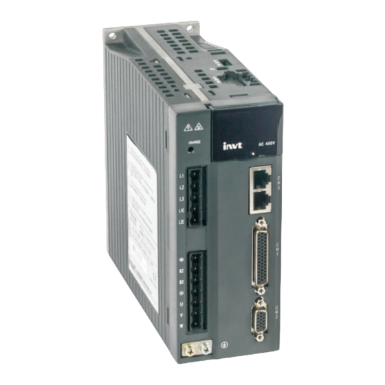
INVT SV-DA200 Series Technical Manual
Ac servo drives, canopen
Hide thumbs
Also See for SV-DA200 Series:
- Operation manual (301 pages) ,
- Technical manual (45 pages) ,
- Technical manual (39 pages)
Table of Contents
Advertisement
Advertisement
Table of Contents

Related Manuals for INVT SV-DA200 Series


Summary of Contents for INVT SV-DA200 Series
- Page 1 Technical Guide SV-DA200 Series AC Servo Drive ——CANopen July 26, 2017...
-
Page 2: Table Of Contents
INVT SV-DA200 Servo Drive CANopen Technical Guide Contents Contents Contents ....................................i 1 Hardware configuration .............................. 1 1.1 Terminal wiring ....................................... 1 1.2 Baud rate setting ...................................... 1 1.3 Precautions ......................................1 2 Software configuration ..............................2 2.1 Basic settings for using CANopen ................................2 2.2 CANopen basics ...................................... -
Page 3: Hardware Configuration
INVT SV-DA200 Servo Drive CANopen Technical Guide 1 Hardware configuration 1 Hardware configuration 1.1 Terminal wiring The CAN communication terminal is on the front panel of an SV-DA200 servo drive, named CN3. The CN3 terminal is a dual-port RJ45 socket, and the the pins of the two ports are numbered in the same way. -
Page 4: Software Configuration
INVT SV-DA200 Servo Drive CANopen Technical Guide 2 Software configuration 2 Software configuration 2.1 Basic settings for using CANopen Before using CANopen on a common SV-DA200 servo drive, you need to set the following three parameters: Set P0.03 (Control mode selection) to 7 (CANopen mode) through the LED panel or ServoPlorer software setting. -
Page 5: Supported Basic Protocols
INVT SV-DA200 Servo Drive CANopen Technical Guide 2 Software configuration Function Code Node-ID Node IDs are defined by the system integrator. The node IDs of SV-DA200 can be modified through the panel or PC software. The node IDs range from 1 to 127 (0 cannot be used). -
Page 6: Sync
INVT SV-DA200 Servo Drive CANopen Technical Guide 2 Software configuration Power-On Initialising Pre-Operational (a,b,c,d) Stopped (a,b) Operational (a,b,c,d,e) After being started, the servo drive automatically switches from Initialising to Pre-Operational. To start a slave station, the master station needs to transmit an NMT command of starting a slave node. After receiving the command, the slave station switches from Pre-Operational to Operational. -
Page 7: Pdo
INVT SV-DA200 Servo Drive CANopen Technical Guide 2 Software configuration The maximum length of ** is 4 bytes, that is, 32 bits. The slave station returns a packet. Daten Identifier 0x580+Node_ID Transmits a Object Object command index sub-index word If the parameter is successfully modified, the command word is 0x60; if the modification fails, the command word is 0x80, and ** is a fault code. - Page 8 INVT SV-DA200 Servo Drive CANopen Technical Guide 2 Software configuration synchronous packets (transmitting the packets at a maximum frequency of 1 kHz). A servo transmits data after receiving a synchronous packet. For TPDOs: Acyclic (0), the servo transmits data only once after receiving a synchronous packet; cyclic (1–240), the servo transmits data once after receiving n synchronous packets;...
-
Page 9: Emcy
INVT SV-DA200 Servo Drive CANopen Technical Guide 2 Software configuration The default transmission type is 254, indicating asynchronous transmission. However, Transmission types of 1–240 (indicating synchronous transmission) are recommended for scenarios with more nodes. You can optimize the load rate of the CAN bus as required. -
Page 10: Operation Modes
INVT SV-DA200 Servo Drive CANopen Technical Guide 3 Operation modes 3 Operation modes 3.1 Profile Position Mode 3.1.1 Basic description A servo drive (slave station) receives a position command transmitted by an upper computer. The position obtained by converting the position command based on the electronic gear ration is used as the target position in the internal position control. -
Page 11: List Of Objects Related To This Operation Mode
INVT SV-DA200 Servo Drive CANopen Technical Guide 3 Operation modes Set 6067 : Following error window to adjust the range of position reached (unit: user-defined unit). 3.1.4 List of objects related to this operation mode Index Name Type Attr. 6040... -
Page 12: Control Word (6040) Of Profile Position Mode
INVT SV-DA200 Servo Drive CANopen Technical Guide 3 Operation modes 3.1.5 Control word (6040) of Profile Position Mode 3.1.6 Status word (6041) of Profile Position Mode 3.1.7 Application example 1. Set 6060 to 1 to select Profile Position Mode. 2. Set 6040 to enable the drive and trigger the position command to take effect. - Page 13 INVT SV-DA200 Servo Drive CANopen Technical Guide 3 Operation modes enable the drive). (2) Set 607A to the target position command. (3) Set 6040 to 0x5F to trigger the position command to take effect (the target position command is triggered to take effect by the edge generated when the value of bit 4 changes from 0 to 1).
-
Page 14: Interpolation Position Mode
INVT SV-DA200 Servo Drive CANopen Technical Guide 3 Operation modes target position command. 3. If multiple target positions are to be transmitted, repeat step 2. Note: SV-DA200 servo drives support the internal caching of 8 steps of target positions. 3.2 Interpolation Position Mode 3.2.1 Basic description... -
Page 15: Application Example
INVT SV-DA200 Servo Drive CANopen Technical Guide 3 Operation modes 60C0 Interpolation sub mode select INTEGER16 60C1 Interpolation data record ARRAY 60F4 Following error actual value INTEGER32 Note: For details about the objects, see the CiA DS402 standard. 3.2.4 Application example Set 6060 to 7 to select Interpolation Position Mode. -
Page 16: Application Example
INVT SV-DA200 Servo Drive CANopen Technical Guide 3 Operation modes 3.3.4 Application example When using the Homing mode, you need to perform the following steps: 1. Set 6060 to 6 to select Homing Mode. 2. Set 6098 to select the homing mode to be used. -
Page 17: Other Objects
INVT SV-DA200 Servo Drive CANopen Technical Guide 3 Operation modes 3.4.3 Other objects 1. Query 6043 : vl velocity demand to obtain the internal rotating speed command (unit: rpm). 2. Query 6044 : vl control effort to obtain the feedback of the actual speed (unit: rpm). -
Page 18: List Of Objects Related To This Operation Mode
INVT SV-DA200 Servo Drive CANopen Technical Guide 3 Operation modes 3.5.4 List of objects related to this operation mode Index Name Type Attr. 6040 Control word UNSIGNED16 6041 Status word UNSIGNED16 6060 Modes of operation INTEGER8 6061 Modes of operation display... -
Page 19: List Of Objects Related To This Operation Mode
INVT SV-DA200 Servo Drive CANopen Technical Guide 3 Operation modes 3.6.4 List of objects related to this operation mode Index Name Type Attr. 6040 Control word UNSIGNED16 6041 Status word UNSIGNED16 6060 Modes of operation INTEGER8 6061 Modes of operation display... -
Page 20: Object Dictionary
INVT SV-DA200 Servo Drive CANopen Technical Guide 4 Object dictionary 4 Object dictionary 4.1 Object specification description 4.1.1 Object type Object name Description Value of a variable, such as UNSIGNED8, Boolean, float, and INTEGER16. ARRAY Array of multiple values, consisting of multiple basic variables of the same type. If Sub-index 0 is of the UNSIGNED8 type, it indicates the number of values in the array but is not part of the ARRAY data. - Page 21 INVT SV-DA200 Servo Drive CANopen Technical Guide 4 Object dictionary Index Object Type Name Data Type Access Mappable 6065 Following error window UNSIGNED32 6066 Following error time out UNSIGNED16 6067 Position window UNSIGNED32 6069 Velocity sensor actual value INTEGER32 606B...
-
Page 22: Overview Of Object Group 2000
INVT SV-DA200 Servo Drive CANopen Technical Guide 4 Object dictionary 4.4 Overview of Object Group 2000 Index Object Type Name Data Type Access Mappable SV-DA200 parameter 2xxx Px-xx INTEGER16/32 3xxx Rx-xx INTEGER16/32 Note: You can access the self-defined parameter area of the drive by simulating the LED panel through SDOs to perform operations, or map the self-defined parameters to PDOs to perform control operations. -
Page 23: Detail Of Object 6041
INVT SV-DA200 Servo Drive CANopen Technical Guide 4 Object dictionary Bits 9 and 10: Reserved. Bits 11–15: Defined by manufacturers. 4.6 Detail of Object 6041 The control word 6041 includes the following content: 1. Bits that indicate the current state of the drive. -
Page 24: Detail Of Object 6060
INVT SV-DA200 Servo Drive CANopen Technical Guide 4 Object dictionary Bits 12 and 13: Operation mode Set-point Homing ip mode reserved Speed reserved Acknowledge attained active Following Max slippage reserved reserved Homing error reserved error error Bits 14–15: Defined by manufacturers. - Page 25 INVT SV-DA200 Servo Drive CANopen Technical Guide 4 Object dictionary message Object Code Data Type UNSIGNED32 Access PDO Mapping Value Range UNSIGNED32 Default Value 0x80 Object 1006 h: Communication Cycle Period Index 0x1006 Communication Cycle Name Period Object Code Data Type...
- Page 26 INVT SV-DA200 Servo Drive CANopen Technical Guide 4 Object dictionary Access PDO Mapping UNSIGNED32 Value Range Default Value Subindex Description Product code Data Type UNSIGNED32 Access PDO Mapping Value Range UNSIGNED32 Default Value Subindex Description Revision number Data Type UNSIGNED32...
-
Page 27: Faults And Diagnosis
INVT SV-DA200 Servo Drive CANopen Technical Guide 5 Faults and diagnosis 5 Faults and diagnosis 5.1 Information format of CANopen communication faults Emergency Object: Byte Content Emergency Error Code Error register Panel Error Code 5.2 CANopen communication faults and solutions... -
Page 28: Da200 Servo Faults And Fault Codes
INVT SV-DA200 Servo Drive CANopen Technical Guide 5 Faults and diagnosis Displayed Fault name Cause Solution code slave station exceeds the allowed 2. Modify the communication baud rate. baud rate range. CAN communication is 1. Check the communication wiring. disconnected or a receiving error 2. - Page 29 INVT SV-DA200 Servo Drive CANopen Technical Guide 5 Faults and diagnosis Displayed 32-bit fault code (16-bit error code + Fault name code 16-bit additional information) Er03-0 Current sensor fault––U-phase current sensor 7300-0300 fault Er03-1 Current sensor fault––V-phase current sensor 7300-0301...
-
Page 30: Sdo Abort Codes
INVT SV-DA200 Servo Drive CANopen Technical Guide 5 Faults and diagnosis Displayed 32-bit fault code (16-bit error code + Fault name code 16-bit additional information) Er24-4 Profibus-DP fault––PZD configuration parameter 8100-1804 property does not match Er25-6 Application fault––Homing offside FF01-1903 Er25-7 Application fault––Inertia identification failure... -
Page 31: References
INVT SV-DA200 Servo Drive CANopen Technical Guide 6 References 6 References 1. CANopen Application Layer and Communication Profile, CiA Draft Standard 301, Version 4.02 Date: 13 February 2002; 2. CANopen Device Profile Drives and Motion Control, CiA Draft Standard Proposal 402, Version 2.0 Date: 17...
Need help?
Do you have a question about the SV-DA200 Series and is the answer not in the manual?
Questions and answers