INVT SV-DA200 Series Technical Manual
Hide thumbs
Also See for SV-DA200 Series:
- Operation manual (301 pages) ,
- Technical manual (39 pages) ,
- Operation manual (286 pages)
Table of Contents
Advertisement
Advertisement
Table of Contents

Subscribe to Our Youtube Channel
Related Manuals for INVT SV-DA200 Series


Summary of Contents for INVT SV-DA200 Series
- Page 2 Change history Release date Version Description First release. Oct. 11, 2018 V1.00 Added PLC communication configuration description. Oct. 25, 2018 V1.01 (1) Added parameters for manually setting device names and IP addresses and related description. Nov. 14, 2018 V1.02 (2) Added IRT communication configuration description. (1) Rectified the by sequence errors of control words (CWs) and status words (SWs).
-
Page 3: Table Of Contents
INVT SV-DA200 AC Servo Drive PROFINET Technical Guide V2.63 Contents 1 Hardware configuration ..........................1 1.1 Terminal wiring .................................. 1 1.2 Electrical connection ................................. 2 1.3 CN1 terminal definition ..............................3 2 Software configuration ........................... 6 2.1 Basic settings of PROFINET application .......................... 6 2.2 PROFINET communication basis ............................. -
Page 4: Hardware Configuration
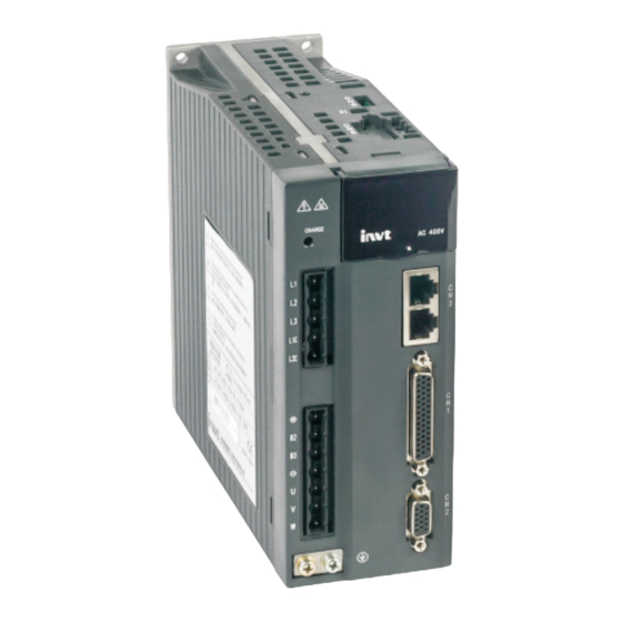
DA200, but different from DA200 in CN1 terminal pins, which are described in section 1.3. The structure of the SV-DA200 series servo drive is as follows: The PROFINET communication card uses two standard RJ45 interfaces, which do not distinguish the direction and can be swappable. -
Page 5: Electrical Connection
INVT SV-DA200 AC Servo Drive PROFINET Technical Guide V2.63 Name Description LED power supply Receive Data- Not connected Ground of the housing Standard RJ45 interface function table State Description Port2: The network is not connected. Port 2: The network communication is... -
Page 6: Cn1 Terminal Definition
RJ45 RJ45 RJ45 Switch Star network topology electrical connection diagram 1.3 CN1 terminal definition SV-DA200 series PROFINET servo drive and standard DA200 model are different in the IO terminals, which are described in the following. Symb Function Symbol Function Reserved... - Page 7 INVT SV-DA200 AC Servo Drive PROFINET Technical Guide V2.63 Symb Function Symbol Function B-phase differential Analog input 2 output - A-phase differential Analog output 1 output - A-phase differential Digital input 7 output + CN1 plug pin layout DO4- DO2+ DO2-...
- Page 8 INVT SV-DA200 AC Servo Drive PROFINET Technical Guide V2.63 Alternative wiring: Drive side Drive side Max load-carrying capacity of Max load-carrying capacity of each output terminal: 30V, each output terminal: 30V, 50mA. 50mA. 12~24V 12~24V DO1+ 3 DO1+ 3 DO1- 4...
-
Page 9: Software Configuration
0 to 127. The value 0 indicates DCP setting, while the other values indicate manual setting. The device name is automatically prefixed with "invt-sv-". For example, when P4.44 is set to 12, the device name is "invt-sv-012". -
Page 10: Profinet Communication Basis
INVT SV-DA200 AC Servo Drive PROFINET Technical Guide V2.63 P4.10 to take effect. You need to set the slave node (servo drive) device name on the master node (CNC or PLC) or through P4.44. The servo drive supports the V0 and V0-1 modified protocol versions (supporting PKW+PZD). - Page 11 INVT SV-DA200 AC Servo Drive PROFINET Technical Guide V2.63 PKE packet format 15 14 AK (Task or Temporarily set to 0 response ID) AK ID Master node to slave node Slave node to master node Positive Negative Function response ID response ID No task.
- Page 12 INVT SV-DA200 AC Servo Drive PROFINET Technical Guide V2.63 16#2000 16#03F2 16#0000_01F4 When the written value (1200) exceeds the max. value (1000) of P0.05 (Jog speed), the negative response ID is 7, and PWE is 2, out of the parameter setting range.
- Page 13 INVT SV-DA200 AC Servo Drive PROFINET Technical Guide V2.63 Function Name Screening digital input (0: CN1 digital input is valid. 1: CN1 digital input is invalid, but the CW is SERVO_DI_INH valid) * Enabling servo SERVO_ON Clearing faults FAULT_CLEAR Emergency stop...
-
Page 14: Dp-V0-1 Optimized Protocol (V2.61 And Later)
INVT SV-DA200 AC Servo Drive PROFINET Technical Guide V2.63 information length, and input and output data count. 2.2.2 DP-V0-1 optimized protocol (V2.61 and later) The parameter P4.79 [PROFINET communication packet type] is set to V0-1 packet, which still uses the 32-byte fixed-length transmission method, to optimize only PZD parameters. -
Page 15: Adding The Gsd File
INVT SV-DA200 AC Servo Drive PROFINET Technical Guide V2.63 Then double-click to open the project view, as shown in the following figure. 2.3.2 Adding the GSD file In the project view, choose Option (N) from the toolbar. Then choose Manage general station description files (GSD). - Page 16 ② Add DA200 drive to the project. In the Hardware catalog panel on the right, choose Other field devices > PROFINET IO > I/O > INVT > INVT Servo Profinet > INVT Profinet Adapter V1.0, and then double-click the INVT Profinet Adapter...
- Page 17 PLC_1.PROFINET interface_1. In the network view, the CPU and INVT PROFINET have been connected to the same PROFINET sub network. ③ Add INVT I/O sub modules to the project. Double-click the INVT Profinet Adapter V1.0 icon to enter the device view. See the following figure.
- Page 18 INVT SV-DA200 AC Servo Drive PROFINET Technical Guide V2.63 On the right, choose Hardware catalog > Module, or double-click or drag the 32 Byte IN/OUT module to the blank area in device view, as shown in the following figure. Then the 32 Byte IN/OUT module has been added to the project.
-
Page 19: Allocating Io Devices
◆ Click the General tab, choose PROFINET interface_1 [X1] > Ethernet addresses, and then set INVT PROFINET parameters, as shown in the following figure. 2.3.4 Allocating IO devices First of all, ensure that the CPU and INVT PROFINET communication card have been connected to your computer through a network cable. - Page 20 Otherwise, devices cannot communicate through PROFINET. ● Click Assign name to assign device names. (Note: The device name invt-1 is used for example, which must be the same as the device name configured on the PROFINET communication card in the project.)
-
Page 21: Saving, Compiling, And Downloading Project Configuration Information
INVT SV-DA200 AC Servo Drive PROFINET Technical Guide V2.63 2.3.5 Saving, compiling, and downloading project configuration information After configuring the project, you need to download the project configuration information to the CPU. See the following figure. Choose Save project to save the project. Right-click PLC_1 [CPU 1511-1 PN] and choose Compile >... - Page 22 INVT SV-DA200 AC Servo Drive PROFINET Technical Guide V2.63 See the following figure.
-
Page 23: Configuring Variable Table Monitoring
INVT SV-DA200 AC Servo Drive PROFINET Technical Guide V2.63 Select the PLC to download (there is only one PLC in the example), and click Download. Click the corresponding buttons, and then Finish. 2.3.6 Configuring variable table monitoring Choose Watch and force tables > Add new watch table in the project tree on the left. -
Page 24: Configuring Irt Communication
Open TIA PORTAL V13, and create a project, which contains one PLC S7-1500, two DA200 servo drives, to which INVT I/O sub modules are added. Set the IP addresses and device names of S7-1500 and DA200. Assign device names invt-1 and invt-1_1 to the two DA200 servo drives online. The project is as... -
Page 25: Setting Connection Attributes
(1) Choose PN/IE_1 > Properties > General > Domain management > Sync domains, and make Sync-Domain_1 valid. See the following figure. (2) Choose Device. Set PLC_1 to the synchronization master node, and set the RT class of INVT-1 and INVT-1_1 to IRT. See the following figure. -
Page 26: Configuring The Plc
2.4.3 Configuring the PLC (1) Click PLC_1. Choose PROFINET interface_1 [X1] > Port[X1 P1 R] > Port interconnection, and set partner ports. In the example, Port1 of the PLC is connected to Port2 of the INVT-1 drive. See the following figure. -
Page 27: Configuring Da200 Drive
2.4.4 Configuring DA200 drive (1) Click INVT-1. Choose PROFINET interface_1 [X1] > Port1- RJ45[X1 P1 R] > Port interconnection, and set partner ports. In the example, Port1 of the INVT-1 drive is connected to Port1 of the INVT-1_1 drive. See the following figure. - Page 28 INVT SV-DA200 AC Servo Drive PROFINET Technical Guide V2.63 (2) Click Synchronization and set the RT class to IRT. See the following figure. (3) Click Isochronous mode on the left, and choose Isochronous mode on the right. See the following...
-
Page 29: Saving, Compiling, And Downloading Project Configuration Information
INVT SV-DA200 AC Servo Drive PROFINET Technical Guide V2.63 (4) Click INVT-1_1, and make similar settings. 2.4.5 Saving, compiling, and downloading project configuration information (1) After the compilation, download the project configuration to the PLC. See the following figure. (2) Set parameter P4.08 to IRT MODE, and save the setting. After soft reset or re-power on, view R0.27 to... -
Page 30: Operation Modes
INVT SV-DA200 AC Servo Drive PROFINET Technical Guide V2.63 3 Operation modes 3.1Position mode–Bus position 3.1.1 Basic description The servo driver (slave node) receives a position command from the upper computer (master node). After electronic gear ratio conversion, the command is used as the target position for internal position control. In this way, position control is implemented. -
Page 31: Position Mode-Internal Ptp
INVT SV-DA200 AC Servo Drive PROFINET Technical Guide V2.63 Set P3.50 (IND = 1700) to adjust the positioning completion range (unit: user unit). 3.2 Position mode–Internal PTP 3.2.1 Basic description The servo driver (slave node) receives a position command from the upper computer (master node). After electronic gear ratio conversion, the command is used as the target position for internal position control. -
Page 32: Other Objects
INVT SV-DA200 AC Servo Drive PROFINET Technical Guide V2.63 Set P4.81 [Configuration of PZD setting parameter 2] (IND = 3202). Check the value of PTP0.01 (unit: user unit). Send the PTP trigger signal through PKW data. Set P0.33 [Position command smooth filter] (IND = 1066). Make the setting take effect immediately. -
Page 33: Speed Mode
INVT SV-DA200 AC Servo Drive PROFINET Technical Guide V2.63 3.3 Speed mode 3.3.1 Basic description In speed mode, the servo drive (slave node) receives a speed command from the upper computer (master node), and plans the speed based on acceleration parameter settings. -
Page 34: Other Objects
INVT SV-DA200 AC Servo Drive PROFINET Technical Guide V2.63 8. Query R0.21 [Transient speed] (IND = 4046) to obtain the actual speed feedback (unit: rpm). 3.4.3 Other objects 1. Set P0.10 [Max. torque limit] (IND = 1020) to modify the limit (unit: 0.1% of rated torque). -
Page 35: Troubleshooting
INVT SV-DA200 AC Servo Drive PROFINET Technical Guide V2.63 4 Troubleshooting 4.1 PROFINET communication faults and solutions Fault Name Possible cause Solution code View the manual and ensure that PROFINET fault–Incorrect The PWK parameter ID is the PWK parameter ID is the... -
Page 36: Da200 Servo Drive Faults And Solutions
INVT SV-DA200 AC Servo Drive PROFINET Technical Guide V2.63 4.2 DA200 servo drive faults and solutions Fault Name Possible cause Solution code The drive actual output current exceeds the specified value. 1. Remove the motor cables and 1. Drive fault (such as drive then enable the drive. - Page 37 INVT SV-DA200 AC Servo Drive PROFINET Technical Guide V2.63 Fault Name Possible cause Solution code encoder reports timeout. 1. Ensure the encoder battery cable is connected properly. 2. Use the multimeter to check When a multi-turn absolute whether the external battery Encoder fault–Encoder...
- Page 38 INVT SV-DA200 AC Servo Drive PROFINET Technical Guide V2.63 Fault Name Possible cause Solution code the drive EEPROM are used for initialization. 1. Ensure encoder cables are connected properly and eliminate the conditions that disturb encoder communication. If the motor is used with a 2.
- Page 39 INVT SV-DA200 AC Servo Drive PROFINET Technical Guide V2.63 Fault Name Possible cause Solution code homing mode The single increment of a Ensure a single travel is not Setting fault–PTP-control Er05-5 PTP idle travel exceeds (2 greater than (2 - 1) in absolute travel overflow position mode.
- Page 40 INVT SV-DA200 AC Servo Drive PROFINET Technical Guide V2.63 Fault Name Possible cause Solution code fault–Communication card card is faulty. 2. If the fault occurs repeatedly, fault replace the communication card. One of the motor cables V and W is short connected to 1.
- Page 41 INVT SV-DA200 AC Servo Drive PROFINET Technical Guide V2.63 Fault Name Possible cause Solution code replace the drive. The detected DC voltage of the drive main circuit is higher 1. Ensure the grid input voltage than the specified voltage. is within the allowed range.
- Page 42 INVT SV-DA200 AC Servo Drive PROFINET Technical Guide V2.63 Fault Name Possible cause Solution code The motor speed absolute value exceeds the setting of P4.32. 1. Ensure the electronic gear 1. The motor stalls or motor ratio is set properly.
- Page 43 INVT SV-DA200 AC Servo Drive PROFINET Technical Guide V2.63 Fault Name Possible cause Solution code 3. The drive force is drive is intact and undamaged, insufficient, which causes and the servo system model is motor stalling. correct. 4. The speed loop control 4.
- Page 44 INVT SV-DA200 AC Servo Drive PROFINET Technical Guide V2.63 Fault Name Possible cause Solution code 3. Increase the ACC/DEC time and reduce the load. The limit switch or software Modify the setting of P5.10 and Application fault–Homing Er25-6 limit is enabled during...
Need help?
Do you have a question about the SV-DA200 Series and is the answer not in the manual?
Questions and answers