Omron fh-l series Vision Controller Manuals
Manuals and User Guides for Omron fh-l series Vision Controller. We have 7 Omron fh-l series Vision Controller manuals available for free PDF download: Reference Manual, User Manual, Hardware Manual, Setup Manual, Hardware Setup Manual
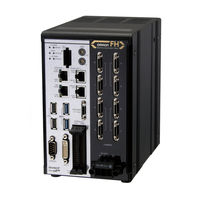
Omron fh-l series Reference Manual (904 pages)
Vision Sensor FH/FZ5 Series
Brand: Omron
|
Category: Accessories
|
Size: 28 MB
Table of Contents
-
-
Input Image25
-
Z341-E155
-
-
Search97
-
Flexible Search112
-
Sensitive Search121
-
ECM Search134
-
EC Circle Search147
-
Shape Search II158
-
Shape Search III170
-
Fz5-L35183
-
Ec Corner192
-
Ec Cross204
-
Classification216
-
Edge Position226
-
Edge Pitch237
-
Scan Edge Width260
-
Intersection294
-
Color Data308
-
Gravity and Area319
-
Labeling333
-
Label Data353
-
Defect357
-
Precise Defect369
-
Fine Matching381
-
Model Dictionary413
-
2D Code419
-
Barcode439
-
Ocr458
-
Circle Angle490
-
Compensate Image509
-
Filtering515
-
Advanced Filter565
-
Panorama609
-
Unit Macro619
-
Calculation621
-
Line Regression632
Advertisement
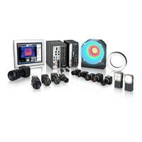
Omron fh-l series User Manual (582 pages)
Vision Sensor
Brand: Omron
|
Category: Machine Vision Systems
|
Size: 26 MB
Table of Contents
-
-
-
-
All Series33
-
FH-L Series34
-
FHV Series35
-
-
Terminology
39 -
-
Features55
-
-
What Is a Scene
174 -
Creating a Scene
177 -

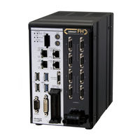
Omron fh-l series User Manual (582 pages)
Brand: Omron
|
Category: Machine Vision Systems
|
Size: 28 MB
Table of Contents
-
Contents
17 -
-
-
Setting]147
-
-
-
What Is a Scene
164 -
Creating a Scene
167
Advertisement
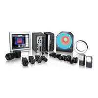
Omron fh-l series User Manual (384 pages)
Vision Sensor
FH Series;
FZ5 Series
Brand: Omron
|
Category: Machine Vision Systems
|
Size: 26 MB
Table of Contents
-
-
-
-
Custom Dialogs105
-

Omron fh-l series Hardware Manual (254 pages)
vision sensor
Brand: Omron
|
Category: Accessories
|
Size: 23 MB
Table of Contents
-
Terminology
29 -
-
Z366-E133
-
-
FH-3 Series36
-
FH-L Series37
-
-
Monitor42
-
Accessories43
-
Cable44
-
Software46
-
-
Camera
81 -
Camera Cable
96
Omron fh-l series Setup Manual (248 pages)
Vision System
Brand: Omron
|
Category: Industrial Equipment
|
Size: 22 MB
Table of Contents
-
Disclaimers15
-
Warning18
-
Grounding20
-
Others20
-
Maintenance23
-
All Series25
-
FH-L Series26
-
Terminology29
-
Monitor41
-
Accessories43
-
Cable44
-
Software46
-
FH-L Series53
-
FH-L Series55
-
FH-L Series74
-
Camera80
Omron fh-l series Hardware Setup Manual (244 pages)
Vision Sensor
Brand: Omron
|
Category: Accessories
|
Size: 18 MB
Table of Contents
-
-
Fh-L3
-
Disclaimers15
-
Warning18
-
Grounding21
-
Others21
-
Maintenance24
-
All Series26
-
FH-L Series27
-
Terminology29
-
Fh-L£££-1037
-
Monitor41
-
Accessories43
-
Cable44
-
Software46
-
FH-L Series53
-
FH-L Series55
-
FH-L Series69
-
Camera75
-
Camera Cable92
-
Lens103
-
Extension Tubes121
-
LCD and Cable144
-
Sysmac Studio147
-
All Series150
-
FH-L Series153
-
All Series156
-
Setup and Wiring156
-
All Series159
-
FH-L Series165
-
All Series175
-
FH-L Series176
-
All Series177
Advertisement