Omron FH-1 series User Manual
Hide thumbs
Also See for FH-1 series:
- User manual (384 pages) ,
- Reference manual (904 pages) ,
- Hardware setup manual (260 pages)
Table of Contents
Advertisement
Quick Links
Advertisement
Table of Contents
Troubleshooting

Related Manuals for Omron FH-1 series


Summary of Contents for Omron FH-1 series
- Page 1 Vision Sensor FH/FHV/FZ5 Series Vision System User’s Manual FH-1/FH-1- FH-2/FH-2- FH-3/FH-3- FH-5/FH-5- FH-L/FH-L- FHV7- FZ5-6/FZ5-6- FZ5-8/FZ5-8- FZ5-11/FZ5-11- FZ5-12/FZ5-12- FZ5-L35/FZ5-L35- Z365-E1-05...
- Page 2 Every precaution has been taken in the preparation of this manual. Nevertheless, OMRON assumes no responsibility for errors or omis sions. Neither is any liability assumed for damages resulting from the use of the information contained in this publication.
- Page 3 Introduction Introduction Thank you for purchasing the FH/FHV/FZ5. This manual provides information regarding functions, performance and operating methods that are required for using the FH/FHV/FZ5. When using the FH/FHV/FZ5, be sure to observe the following: • The FH/FHV/FZ5 must be operated by personnel knowledgeable in electrical engineering. •...
- Page 4 Related Manuals Related Manuals The followings are the manuals related to this manual. Use these manuals for reference. Name of Manual Man.No. Model Proposes Contents Vision System FH 9607479-9 FH-1 To confirm the safety and Describes the definitions of basic Instruction Sheet FH-1-...
- Page 5 Related Manuals Name of Manual Man.No. Model Proposes Contents Vision System Z365 FH-1 When User want to know Describes the soft functions, FH/FHV/FZ5 Series FH-1- how to setup the Sensor setup, and operations to use User’s FH-2 Controller of the Vision Sensor Controller of the Vision Manual FH-2-...
- Page 6 Manual Structure Manual Structure Page Structure The following page structure and icons are used in this manual. Level 1 heading 4 Installation and Wiring Level 2 heading Mounting Units Level 3 heading Level 2 heading Gives the current headings. Level 3 heading 4-3-1 Connecting Controller Components The Units that make up an NJ-series Controller can be connected simply by pressing the Units together...
- Page 7 Manual Structure Special Information Special information in this manual is classified as follows: Precautions for Safe Use Precautions for Safe Use Precautions on what to do and what not to do to ensure safe usage of the product. Precautions for Correct Use Precautions on what to do and what not to do to ensure proper operation and performance.
- Page 8 Manual Structure Conventions Used in This Manual • Use of Quotation Marks and Brackets In this manual, menus and other items are indicated as follows. Menu Indicates the menu names or processing items shown in the menu bar. Item name Indicates the item names displayed on the screen.
- Page 9 Definitions of Basic Terms Definitions of Basic Terms Term Definition FH Series All FH series model names as follows: FH-1, FH-1-, FH-2, FH-2-, FH-3, FH-3-, FH-5, FH-5-, FH-L, FH-L- FH-1000 series All FH-1 series model names as follows: FH-1, FH-1- FH-2000 series All FH-2...
- Page 10 Definitions of Basic Terms Term Definition processing item Any of the individual items for vision inspections that are partitioned and packaged so that they can be flexibly combined. These include the Search, Position Compensation, and Fine Matching items. Processing items can be classified for image input ([Input image]), inspection/mea- surement ([Measurement]), image correction ([Compensate image]), inspection/mea- surement support ([Support measurement]), process branching ([Branch]), results external output ([Output result]), resulting image display ([Display result]), etc.
- Page 11 Definitions of Basic Terms Term Definition operation Double A mode that processes the measurement flow for the first trigger and then processes modes Speed the measurement flow in parallel for the second trigger to achieve a high-speed trigger Multi-input input interval. It is used together with the multi-input function. Multi-line A trigger mode that allows you to independently processing multiple measurement Ran-...
- Page 12 Definitions of Basic Terms Term Definition Position compensation When the location and direction of measured objects are not fixed, the positional devi- ation between reference position and current position is calculated and measurement is performed after correcting. Please select processing items that are appropriate to the measurement object from processing items that are related to position compensation.
- Page 13 Definitions of Basic Terms Term Definition 2's complement Binary numbers are generally used to represent negative numbers. Negative numbers are expressed by "Inverting all bits of a positive number and adding 1 to the result". (Example) "−1" is expressed as 2's complement "−1"...
- Page 14 Definitions of Basic Terms Vision System FH/FHV/FZ5 Series User’s Manual (Z365)
- Page 15 Sections in this Manual Sections in this Manual Saving/ Overview Loading Data Advanced Usage Features Basic What to Do! Operations Using Tools Appendices Creating Measurement Index Scenes Performing Measurement and Adjustment Increasing/Switching Measurement Scenes Setting Windows Vision System FH/FHV/FZ5 Series User’s Manual (Z365)
-
Page 16: Table Of Contents
CONTENTS CONTENTS Introduction ......................1 Related Manuals ....................... 2 Manual Structure ...................... 4 Page Structure ............................. 4 Special Information ............................5 Conventions Used in This Manual ....................... 6 Definitions of Basic Terms ..................7 Sections in this Manual ..................13 CONTENTS...................... -
Page 17: Contents
CONTENTS Basic Knowledge about Operations ..................3-6 3-2-1 Inputting Values .......................... 3-6 3-2-2 Inputting Text ..........................3-7 3-2-3 Selecting Files and Folders ...................... 3-10 3-2-4 Available Operations in Select File Window ................3-13 3-2-5 Using the Zoom Function......................3-14 3-2-6 Setting Figures.......................... - Page 18 CONTENTS Section 5 Creating Measurement Scenes What Is a Scene? ........................5-2 Creating a Scene ........................5-5 Editing Processing Units in Scenes ..................5-7 Displaying and Checking Processing Branches in a Scene ........... 5-10 Using Variables to Edit the Flow [TDM Editor] ..............5-14 5-5-1 Edit Flow Screen ........................
- Page 19 CONTENTS Editing Scenes [Scene Maintenance] .................. 7-6 7-3-1 Copying Scenes.......................... 7-6 7-3-2 Deleting Scenes.......................... 7-6 7-3-3 Renaming a Scene and Adding a Description ................7-7 Editing Scene Groups [Scene Maintenance] ..............7-8 7-4-1 Copying and Deleting Scene Groups ..................7-8 7-4-2 Renaming the Scene Group Name.....................
- Page 20 CONTENTS Section 9 Saving/Loading Data Saving Data to the FH series/FZ5 series ................9-3 9-1-1 About Saving Areas ........................9-3 9-1-2 External Drive Names ......................... 9-5 9-1-3 Using External Storage Devices ....................9-6 9-1-4 Shared Folder on a Computer Connected to the Network ............9-6 Saving Settings Data to the Flash Memory .................
- Page 21 CONTENTS 10-5 Setting the Keyboard Layout for the Controller [Keyboard Layout Selection Tool] ... 10-44 10-6 Switching User Accounts ....................10-45 10-6-1 Logging in ..........................10-45 10-6-2 Logging out ..........................10-46 10-7 Customizing Communication Commands [Communication Command Macro] ..10-47 10-8 Extending the Functions in a Measurement Flow or Scene [Scene Control Macro Tool] ....................
- Page 22 CONTENTS Index Vision System FH/FHV/FZ5 Series User’s Manual (Z365)
- Page 23 CONTENTS Vision System FH/FHV/FZ5 Series User’s Manual (Z365)
-
Page 24: Terms And Conditions Agreement
Omron’s exclusive warranty is that the Products will be free from defects in materials and workman- ship for a period of twelve months from the date of sale by Omron (or such other period expressed in writing by Omron). Omron disclaims all other warranties, express or implied. - Page 25 Disclaimers Performance Data Data presented in Omron Company websites, catalogs and other materials is provided as a guide for the user in determining suitability and does not constitute a warranty. It may represent the result of Omron’s test conditions, and the user must correlate it to actual application requirements. Actual performance is subject to the Omron’s Warranty and Limitations of Liability.
-
Page 26: Safety Precautions
Safety Precautions Safety Precautions Symbols and the meanings for safety precautions described in this manual. In order for the product to be used safely, the following indications are used in this book to draw your attention to the cautions. The cautions with the indications describe the important contents for safety. - Page 27 Safety Precautions Alert statements in this Manual WARNING This product must be used according to this manual or Instruction sheet. Failure to observe this may result in impairment of functions and performance of the product. This product is not designed or rated for ensuring safety of persons. Do not use it for such purposes. Never connect the AC power supply with this product.
-
Page 28: Precautions For Safe Use
(d) Applications under conditions and environment not described in specifications *1. In addition to the applications listed from (a) to (d) above, Omron products (see definition) are not intended for use in vehicles designed human transport (including two wheel vehicles). Please do NOT use Omron prod- ucts for vehicles designed human transport. - Page 29 • When attaching the lighting module, use S8VK-G06024 (OMRON) or S8VS-06024 (OMRON). • When not attaching the lighting module, use S8VK-G06024 (OMRON) or S8VS-06024 (OMRON). • Wire high-voltage cables or power cables separately from the cables of this product. If the same cable or duct is used, the product may receive induction and it may cause malfunctioning or break- age.
- Page 30 Precautions for Safe Use • If using an I/O cable 20 m long, confirm that the power supply output is 24 VDC or higher. If it is lower than 24 VDC, the product does not operate. • Cut off unnecessary signal wires so that they do not contact any other signal wires. •...
- Page 31 • Do not attempt to dismantle, repair, or modify the product. • Should you notice any abnormalities, immediately stop use, turn OFF the power supply, and contact your OMRON representative. • While the power is ON or immediately after the power is turned OFF, the Sensor Controller and cam- era case are still hot.
- Page 32 • If anything abnormal occurs, for example, strange smell/sound is detected, the main unit gets very hot, or a smoke comes, stop using the product, turn OFF the product, and consult OMRON’s branch or sales office.
-
Page 33: Precautions For Correct Use
Precautions for Correct Use Precautions for Correct Use Installation and Storage Sites for FH-1000/2000/3000/5000 series/FZ5-800/1100/1200 series/FZ5-600 series/FZ5-L series Install and store the product in a location that meets the following conditions: • Surrounding temperature of 0 to +50°C * • No rapid changes in temperature (place where dew does not form) •... - Page 34 Precautions for Correct Use Orientation of Product • For good heat dissipation, install the product only in the position written this manual or Instruction sheet so as not to block the ventilation holes. Ambient Temperature • For good heat dissipation, keep the distance written this manual or Instruction sheet. •...
- Page 35 Precautions for Correct Use Component Installation and Handling (FHV series) • If using a commercially available switching regulator, earth the frame ground terminal. • If the power supply line has surge, connect a surge absorber according to the operational environ- ment to use the product.
- Page 36 Precautions for Correct Use Communication with High-order Device • After confirming that this product is started up, communicate with the high-order device. When this product has started up, an indefinite signal may be output from the high-order interface. To avoid this problem, clear the receiving buffer of your device at initial operations.
- Page 37 Precautions for Correct Use Failsafe Measures (FHV series) • When operating a stage or robot using measurement results of the Smart Camera (axis moving dis- tance output by the calibration or alignment measurement), take measures as follows: Be sure to operate the stage or robot after confirming the measurement result data on the stage or robot side that the data are within the movable range of the stage or robot.
- Page 38 Precautions for Correct Use LED Safety (FHV series) This product is classified into the following risk groups by IEC62471. Model Color LED safety Display FHV-LTM-W White Risk group 2 FHV-LTM-R Risk group 1 FHV-LTM-IR Infrared light Risk group 1 Risk group 1 Green Risk group 2 FHV-LTM-MC...
-
Page 39: Regulations And Standards
• If the level of disturbance of the video is such that characters on the monitor are readable, the test is a pass. • This product complies with EC/EU Directives. EMC-related performance of the OMRON devices that comply with EC/EU Directives will vary depending on the configuration, wiring, and other conditions of the equipment or control panel on which the OMRON devices are installed. -
Page 40: Fh-L Series
• If the level of disturbance of the video is such that characters on the monitor are readable, the test is a pass. • This product complies with EC/EU Directives. EMC-related performance of the OMRON devices that comply with EC/EU Directives will vary depending on the configuration, wiring, and other conditions of the equipment or control panel on which the OMRON devices are installed. -
Page 41: Fhv Series
• EU Directive 2014/30/EU (After April 20 2016)/EU EN61326-1 Electromagnetic environment: Indus- trial electromagnetic environment (EN/IEC 61326-1 Table 2) • This product complies with EC/EU Directives. EMC-related performance of the OMRON devices that comply with EC/EU Directives will vary depending on the configuration, wiring, and other conditions of the equipment or control panel on which the OMRON devices are installed. -
Page 42: Revision History
Revision History Revision History A manual revision code appears as a suffix to the catalog number on the front and back covers of the manual. Z365-E1-05 Cat. No. Revision code Rev. No. Rev. Date Revision Contents Software Version Apr. 2016 Additional descriptions of software updates, FH-L Ver. -
Page 43: Overview
Overview This section describes the basic flow and preparations that are necessary to start oper- ation. 1-1 Checking the System Configuration ......1-2 1-1-1 System Configuration . -
Page 44: Checking The System Configuration
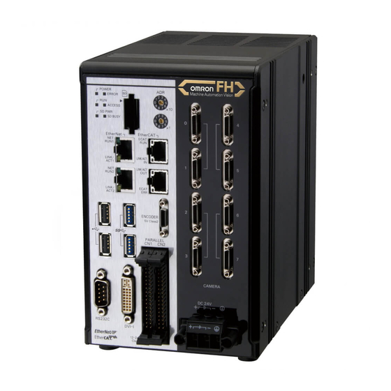
1 Overview Checking the System Configuration 1-1-1 System Configuration The FH/FHV/FZ5 is a Vision Sensor that uses a controller to process measurements of objects that are imaged with a Camera. You connect an LCD for operations and monitoring, and various Cameras to the FH/FHV/FZ5-series Sensor Controller. -
Page 45: Functional Comparison Between The Fh-Series, Fhv-Series And Fz5-Series Controllers
1 Overview 1-1-2 Functional Comparison between the FH-series, FHV-series and FZ5-series Controllers The following table shows the differences between the FH series, FHV series and FZ5 series. The fastest measurement speed is FH-5000 series.The next speed is the following:FH-5000 series > FH-3000 series >... - Page 46 *5. Output to an external monitor is disabled in the default settings. If output to an external monitor is needed, contact your OMRON representative. System Settings Sensor Controller's Model...
- Page 47 1 Overview Sensor Controller's Model FH series FZ5 series FZ5- 1000/ Menu Group Parameter 800/ Menu 2000/ FH-L FZ5-L series 1100/ 3000/ series series 1200 series 5000 series series Cam- Camera Camera 0 connec- to 7 tion Inter- STEP camera camera setting Delay 0 to 7...
- Page 48 1 Overview *6. Operation mode tab is not displayed. *7. Parallel processing tub is not displayed. *8. Depending on the number of camera port of Sensor Controller. *9. Enable only STEP 0 to 2. *10.Enable only STEP 0. *11. Enable only DSA 0 to 2. *12.Enable only DSA 0.
-
Page 49: Flow Of Application
1 Overview Flow of Application The following table shows the flow for using the FH/FHV/FZ5. Procedure Description Reference Preparations Installation and Wiring Vision System FH/FZ5 Series Hardware Setup Manual (Cat. No. Z366) FH Instruction Manual FZ5 Instruction Manual FHV Series Smart Camera Setup Manual (Z408) FHV Instruction Manual ↓... - Page 50 1 Overview Procedure Description Reference ↓ Scene Editing In the Main Window (layout 0), edit the mea- Refer to Section 5 Creating Measurement surement flow. Scenes on page 5-1 • Register processing items. • Set the properties for each processing item. ↓...
-
Page 51: Features
Features A measurement flow consist of a series of combined processing items and is called a scene. This section explains how to create and edit scenes. 2-1 Basic Mechanism for Measurements ......2-2 2-2 Support for a Variety of Scenes and Measurement Lines . -
Page 52: Basic Mechanism For Measurements
2 Features Basic Mechanism for Measurements An FH/FHV/FZ5-series Sensor Controller uses pre-built packages that contain all the processing tasks (for image input, measurement processing, displays, outputs, etc.) that are required for vision inspec- tions. You arrange these packaged processes in order of execution of the vision inspection. An FH/FHV/FZ5-series Controller executes vision inspections according to user-created flows. - Page 53 2 Features play processing, input and output processing, and settings dialog boxes that are custom-tailored to your application. 2 - 3 Vision System FH/FHV/FZ5 Series User’s Manual (Z365)
-
Page 54: Support For A Variety Of Scenes And Measurement Lines
2 Features Support for a Variety of Scenes and Measurement Lines You can have more than one setting for a measurement flow, depending on the inspections. This is called a scene and you can set up to 128 scenes. Refer to 5-1 What Is a Scene? on page 5-2. You can also combine more than one scene into a scene group. - Page 55 2 Features If you have more than one measurement line, the FH allows you to selectively execute up to eight mea- surement lines. This allows you to maintain settings for the scenes and scene groups for every line from 0 to 7. You can connect up to eight Cameras to the FH, (four for the FZ5), and selectively control each Cam- era.
- Page 56 2 Features 2 - 6 Vision System FH/FHV/FZ5 Series User’s Manual (Z365)
-
Page 57: Basic Operations
Basic Operations This section describes test methods for checking whether correct measurement can be performed at the set conditions and describes useful functions for operation. 3-1 Preparing the Controller and Cameras ......3-2 3-1-1 Camera Setup . -
Page 58: Preparing The Controller And Cameras
3 Basic Operations Preparing the Controller and Cam- eras 3-1-1 Camera Setup FH series/FZ5 series Sensor Controllers use the CameraLink standard for camera connection. At nor- mal camera connection, a single camera cable is used for a single camera, and each camera is con- nected to the Sensor Controller in the CameraLink base configuration. - Page 59 3 Basic Operations Using Two Cables for High-frame-rate Camera Use (FH series only) FH series Sensor Controllers support the CameraLink standard’s Base Configuration and Medium Con- figuration. The Medium Configuration enables use at a higher frame rate than the Base Configuration, reducing image input time.
-
Page 60: Preparing A Controller
3 Basic Operations Camera number in application software Sensor Con- troller cam- Example when combining Example when all cameras Example when all cameras one- and two-cable connec- use one-cable connection use two-cable connection connector tion number Line 0 Line 1 Line 0 Line 1 Line 0... -
Page 61: Adjusting The Camera
3 Basic Operations 3-1-3 Adjusting the Camera Check the images that are being taken. Adjust the position of measurement objects and the focus of the lens. Click the upper left corner of the Image Pane, and then select [Image mode] − [] − [Through]. The through image from the Camera is displayed in the Image Pane. -
Page 62: Basic Knowledge About Operations
3 Basic Operations Basic Knowledge about Operations 3-2-1 Inputting Values This section describes how to input values required for setting the judgement conditions and communi- cation specifications. Methods for setting up values include the following, depending on the settings. • Specify values directly with the numeric keyboard Used to enter specific values, or to fine-tune the value with the UP and DOWN keys. -
Page 63: Inputting Text
3 Basic Operations 3-2-2 Inputting Text This section describes methods for inputting file names and descriptive text. Screen keyboard The following software keyboard is displayed in the window for inputting text depending on the sensor controller. Switching operation will differ depending on the screen keyboard. ... - Page 64 3 Basic Operations • Use the following procedure to switch kana-kanji conversion ON/OFF. To input kanji characters, it is necessary to start the IME. There are two ways to do this. To toggle between IME ON/OFF, press [Alt] + [~] (tilde). To use the [Alt] + [~] key combination, first hold down [Alt], and while doing so, press and press again [~].
- Page 65 3 Basic Operations Operation Method Click [...] in the item in which a character string is to be set. The soft keyboard is displayed. Switch the tabs as needed and Click the character that is to be input. Depending on the used languages settings (Refer to 4-1 Selecting Language [Startup Settings] on page 4-2 in order to switch display languages, input characters using the following format.
-
Page 66: Selecting Files And Folders
3 Basic Operations 3-2-3 Selecting Files and Folders This section describes data save/load methods and operation methods for when selecting a save desti- nation folder for images created during remeasurement, etc. The following window will appear in the window to select a file or a folder. (a) Window Title When a file is specified, "FileExplorer"... - Page 67 3 Basic Operations (d) List View Area A list of files and folders contained in the folder selected from the folder view area is displayed. In addition, when an extension name is selected from "Kind", only the files with the selected exten- sion name are displayed.
- Page 68 3 Basic Operations When you select BMP(BFZ) file type on the 2 area. (1) Selecting BFZ file type in FIleExplore, it is processed as a file. In this case, those files are processed same as a measurement object file. (2) If multiple images are saved to selected BFZ file, saved image will display on the left-lower window (under part of 1).
-
Page 69: Available Operations In Select File Window
3 Basic Operations 3-2-4 Available Operations in Select File Window This section describes the main operations available from the Select File window. Additional Information If the target file is not displayed in the list view area when selecting a file, please check that the file type of the target file is selected in "Kind". -
Page 70: Using The Zoom Function
3 Basic Operations 3-2-5 Using the Zoom Function You can adjust the window scaling for the image display on the image display area of Properties Dialog Box. (a) Zoom browser Indicates where the zoom display area is in the original image. (b) Magnification factor Input the magnification factor A factor of between 25% to 1600% can be indicated. -
Page 71: Setting Figures
3 Basic Operations 3-2-6 Setting Figures This section describes the setting method for objects (figures and text) when you register Model or set the measurement region on the Properties Dialog Box of Processing units. The type and number of objects varies depending on different setting options. Layout of Figure Setting Area Window for registering figures when registering or setting areas or models as measurement objects. - Page 72 3 Basic Operations (b) [Edit] You can edit on the Properties Dialog Box when related figures are set. By clicking [Edit] button, the following figure editing tool will be displayed. (1) Drawing tool buttons Sets up objects, such as figures and text. The number and type of objects available is differ- ent depending on the applicable setting (ex.
- Page 73 3 Basic Operations Setting Methods Rectangle • Image selection status • Dimension Adjustment • Example) When enlarg- Points are displayed at Drag the lower right point each of the four corners. down in a diagonal direc- tion. • Using numbers for setting The setting area consists of two windows below.
- Page 74 3 Basic Operations Circle/Ellipse • Image selection status • Dimension Adjustment Drag the points. Points are dis- played on the top, bottom, left, right, and lower right of the circle. • Example) When zooming in on a circle • Example) When transforming a circle into a long horizontal ellipse Drag the point on the lower right of the circle.
- Page 75 3 Basic Operations Circumference • Image selection status • Dimension Adjustment Drag the points. Points are displayed on the top, bottom, left, and right of both the inner and outer circles. • Example) When enlarging the entire cir- • Example) When adjusting the width of the cumference circumference Drag a point on the outer circle.
- Page 76 3 Basic Operations Arc • Image selection status • Dimension Adjustment Drag the points. Points are displayed on two lines at both ends of the arcs, inside of the two lines at both ends of the arcs, on the inner arc, on the outer arc, and inside the closed arc shape.
- Page 77 3 Basic Operations Crosshair Cursor • Image selection status Entire image is selected. • Using numbers for setting Setting is performed through input of numbers or through tapping on the arrows. The line type and line color can also be changed at this window. ...
- Page 78 3 Basic Operations • Using numbers for setting The setting area consists of two windows below. Click the [1] or [2] on the right side of the window to select the setting item. Text • Image selection status Entire image is selected. Additional Information •...
- Page 79 3 Basic Operations About OR Setting/NOT Setting The OR setting/NOT setting is used when multiple images are combined. Areas with complex shapes can be drawn through combining figures, and unnecessary parts can be excluded form the area. Each time [OR/NOT] ( ) is tapped, the setting of the selected figure toggles between OR and NOT.
-
Page 80: Changing The Image Mode And Other Display Contents
3 Basic Operations 3-2-7 Changing the Image Mode and Other Display Contents The display contents of the Image Pane can be changed in order to make the measurement status eas- ier to understand. Click the upper left corner of the Image Pane that for which to change to display the settings dia- log box for the Image Pane. -
Page 81: Changing The Display Ratio
3 Basic Operations 3-2-8 Changing the Display Ratio When you use the FH series/ FZ5-1100 series, you can change the display magnification as follows: Click the zoom icon in the upper right corner of the Image container window. The zoom icon color is changed, and then the Display Ratio can be changed by using mouse wheel. - Page 82 3 Basic Operations Additional Information • If a measurement trigger is input while using the multi-input function or immediately after BUSY is turned OFF (such as while the display is being updated), the last NG image cannot be displayed. • [Display Last NG Image] serves a similar function as a processing item for which error images can be saved.
-
Page 83: Checking System Information
You can check the external storage status only on the FH series and the FZ5-800/1100/1200 series. Refer to 9-1-3 Using External Storage Devices on page 9-6. Additionally, you can use a Firmware upgrade tool. Make sure to contact your OMRON representative. Additional Information Firmware upgrade tool is a software used when changing the version of the measurement application soft. - Page 84 3 Basic Operations About [Drive information] button Click the [Drive information] button. The information of the drive that is connected to the Sensor Controller is can be checked. Refer to 9-1-2 External Drive Names on page 9-5 and 9-1-3 Using External Storage Devices on page 9-6.
- Page 85 3 Basic Operations Displayed item Description The number of application process Differs depending on the Sensor Controller mode. Refer to 4-4 Set- ting Operation Mode [Startup Settings] on page 4-12. Standard = 1 Double Speed Multi-input = 2 Non-stop adjustment = 2 (Operation: Process 0, Adjustment: Process 1) Multi line random trigger mode = Number of set lines (Each line number corresponds to the process number).
- Page 86 3 Basic Operations Status Countermeasures Image value is too large. Modify the Scenes and reduce the filter units. Replace some filtering processing into one advanced filter. Or lower the camera resolution. Additional Information The Memory state window can be displayed from Measurement Manager Bar, as well as taking above steps starting from System information.
-
Page 87: Checking The Memory Consumption And Percentage Of Memory Used
3 Basic Operations Checking the Memory Consumption and Percentage of Memory Used The Memory state window that shows the memory used in the sensor controller can be opened from the Measurement Manager Bar. Click the [M] button on the Measurement Manager Bar of the Main Window. The Memory state window is displayed. -
Page 88: Capturing Screen Images
3 Basic Operations Capturing Screen Images The contents displayed in the run window can be captured. Saved images can be loaded into the com- puter and pasted into documents. Set the Destination for Captured Images Use the following procedure to set the save destination for the image captured with the screen capture function. - Page 89 3 Basic Operations Saving Captured Images Click the [Capture] button that is displayed on the Measurement Manager Bar that is located in the bottom right corner. Important The capture takes a few seconds and measurement cannot be performed during that time period.
-
Page 90: Saving Settings Before Turning Off The Power And Restarting
3 Basic Operations Saving Settings before Turning OFF the Power and Restarting 3-6-1 Saving the Setting to the Controller [Data Save] Before you turn OFF the power supply to the Controller, save the data that you have set to the flash memory in the Controller. -
Page 91: Device Information Storage Tool
3 Basic Operations 3-6-2 Device Information Storage Tool This tool will prevent issues happening at start-up of the Sensor Controller due to recognition delay for external devices. Be sure to execute this tool when connecting external devices. For example, the fol- lowing issues can be solved. - Page 92 3 Basic Operations Click [OK]. The following “Executing” dialog box is displayed to indicate the processing progress. When the processing is completed, the dialog box is automatically closed. Important • Do not reboot or turn off the Sensor Controller while the “Executing” dialog box is displayed. The data and the external device may corrupt.
-
Page 93: Restarting The Controller: [System Restart]
Restarting with Remote Operation End the remote operation. For the operation method, refer to 10-1-3 Terminating Remote Operation on page 10-13. From the [Start] menu on your PC, select [All Programs] - [OMRON] - [FZ_FH Series] - [FH_FHV Launcher]. FH/FHV Launcher window appears. - Page 94 3 Basic Operations Click [Browse]. A "Network reference" list will be displayed. When you run the simulation software of the sensor controller on the remote operation side PC, the simulation software information may be displayed in the Network reference list. Select your target Sensor Controller from the list, click [Restart].
-
Page 95: Initializing The Controller
Initializing with Remote Operation End the remote operation. For the operation method, refer to 10-1-3 Terminating Remote Operation on page 10-13. From the [Start] menu on your PC, select [All Programs] - [OMRON] - [FZ_FH Series] - [FH_FHV Launcher]. FH/FHV Launcher window appears. - Page 96 3 Basic Operations Click the [Run] button. Note that the Sensor Controller must be placed in a measurement capable state. Precautions for Correct Use Do not connect or disconnect the [Remote Operation Tool] during a measurement or the sys- tem running. Click [Browse].
-
Page 97: Turning Off The Lcd
3 Basic Operations Turning OFF the LCD 3-8-1 Turning OFF the LCD [LCD OFF] (This function is supported only by the FZ5-600/800/1100/1200 series LCD-integrated Controllers.) You can turn OFF the LCD without turning OFF the Controller. Click the [LCD off] button that is located on the Measurement Manager Bar in the lower right corner of the window. - Page 98 3 Basic Operations 3 - 42 Vision System FH/FHV/FZ5 Series User’s Manual (Z365)
-
Page 99: Setting The Controller
Setting the Controller This section describes settings related to the system environment for the controller. 4-1 Selecting Language [Startup Settings] ......4-2 4-2 Setting the Status at Startup [Startup Settings] . -
Page 100: Selecting Language [Startup Settings]
4 Setting the Controller Selecting Language [Startup Set- tings] You can set the language to use for the characters displayed on the displays. Information about the application software will be displayed in the selected language. Additional Information • When a Controller with default settings is started, the [Language setting] dialog box is automatically displayed. -
Page 101: Setting The Status At Startup [Startup Settings]
4 Setting the Controller Setting the Status at Startup [Startup Settings] You can set the status when the power supply is turned ON. Inspection will start immediately after the power supply is turned ON, if you select the Scene number and Scene group number that sets measurement contents. - Page 102 4 Setting the Controller Set value Setting Item Description [Factory default] Operation priority Selects the operation priority to either measurement results display or menu operation. [Measurement Processing of measurement results display is given pri- result priority] ority. Menu operation will be harder to receive because of its lowered priority status.
- Page 103 4 Setting the Controller Important *1 For FH series/FZ5-800/1100/1200 series, [Relocate memories] setting is invalid. *2 Relocate processing could be take time depends on relocated data capacity or data frag- mentation when [Relocate] is selected. *3 An error may occur; e.g. data is insufficient because data relocate processing is not carried out when [Relocate] is selected.
-
Page 104: Setting Communication [Startup Settings]
4 Setting the Controller Setting Communication [Startup Set- tings] Select the type of Communications Module to determine the communications method to use for communications between the Sensor Controller and external device. Refer to the Vision System FH/FHV/FZ5 Series User's Manual for Communications Settings (Cat. - Page 105 4 Setting the Controller Important • Do not set [EtherNet/IP] and [PLC Link] at the same time. They cannot be used at the same time. Example: Set [Serial (Ethernet)] to [PLC Link] and [Fieldbus] to [EtherNet/IP] at the same time. Set [Serial (RS-232C/422)] to [PLC Link] and [Fieldbus] to [EtherNet/IP] at the same time.
- Page 106 4 Setting the Controller Settings for Touch Panel Monitor An exclusive touch screen monitor, Touch Panel Monitor is available for FH Sensor Controllers to con- firm images or to display menus for condition settings. Important • The Touch Panel Monitor (FH-MT12) is used exclusively with the FH series Sensor Control- lers.
- Page 107 4 Setting the Controller For monitor cable of video input or communication cable of Touch Panel, refer to the followings: Connection cable for FH-MT12 Cable name Type Cable length Model Minimum bend radius Monitor cable DVI-RGB converter FH-VMDA 2M 36 mm cable FH-VMDA 5M...
- Page 108 4 Setting the Controller Click [Apply]. Click [Close]. Click [Data save] in the tool bar on the Main Window and then click [OK] on the "Data save" dia- log box displayed. Click [System restart] in the [Function] menu on the Main Window. Click [OK] on the [System restart] dialog.
- Page 109 4 Setting the Controller Difference in Touch Panel Monitor Communications There are two types of connections for touch panel communication: USB connection and RS-232C con- nection. Normally use a USB connection for the touch panel. Use an RS-232C connection in the following cases. •...
-
Page 110: Setting Operation Mode [Startup Settings]
4 Setting the Controller Setting Operation Mode [Startup Set- tings] Select the operation mode according to the application conditions, such as the operation mode that is best suited to reduce the takt time and downtime. Refer to 4-4-1 Setting the Operation Mode on page 4-13 for details on the operation modes. Item Set value [Factory default] Description... -
Page 111: Setting The Operation Mode
4 Setting the Controller 4-4-1 Setting the Operation Mode This section describes the operation mode (FH series and FZ5-800/1100/1200 series only). You can use a multi-core CPU to set the operation mode according to the application conditions. This helps to reduce the takt time and downtime. - Page 112 4 Setting the Controller Selection Guide for Operation mode A guide to using the most suitable operation mode for your purpose. Select Operation mode You want to measure on multiple lines. Measures on multiple lines : Trigger input for each line. : Trigger input for each line.
- Page 113 4 Setting the Controller Double Speed Multi-input You can execute the measurement process with a multi-core CPU to inspect more measurement tar- gets in less time than conventional processing would allow. This mode uses up to four CPU cores (or eight threads) on a CPU that take turns in the execution of a single inspection flow every time the STEP signal is input.
- Page 114 4 Setting the Controller About Double Speed Multi-input Two cores performs the same inspection flow alternatively, which help to shorten measurement takt time. Example: Normal processing with a single core CPU STEP STEP Camera processing Processing with core 0 Shortest takt time Camera processing Measurement processing...
- Page 115 4 Setting the Controller Important • Click the upper left of the Image Display Pane and set the [Image mode] to [Freeze Image]. Refer to 3-2-7 Changing the Image Mode and Other Display Contents on page 3-24. • If images are taken consecutively at high speed, the number of images that you will be able to take will be limited.
- Page 116 4 Setting the Controller OK:Supported processing item, RST: Processing item with restricted support, ---:Unsupported processing item Sup- Sup- Sup- Processing item Processing item Processing item port port port Camera Image Input Back Ground Suppression Transfer Position Data Camera Image Input FH Brightness Correct Filter Calc Axis Move Camera Image Input FHV...
- Page 117 4 Setting the Controller Multi-line Random-trigger Mode You use the Multi-line Random-trigger Mode when you want to measure more than one line with a sin- gle Controller. You can measure the inputs from different Cameras on up to eight independent lines. You can set a scene group data and scene data for each line.
- Page 118 4 Setting the Controller FH-1000/3000/5000 series Sensor Controller You can assign any of up to eight Cameras to each line. Use the following procedure to assign Cameras to each line. In the Main Window, select [System settings] − [Startup] − [Startup settings] from the [Tool] menu.
- Page 119 4 Setting the Controller Functional Limitations of Multi-line Random-trigger Mode Keep the following points in mind when using Multi-line Random-trigger Mode. FH series: FZ5 series: Item FH-1000/3000/5000 series FZ5-800/1100/1200 series Processing time • If the processing load for multiple •...
- Page 120 4 Setting the Controller FH series: FZ5 series: Item FH-1000/3000/5000 series FZ5-800/1100/1200 series Communi- EtherNet/IP • To use EtherNet/IP, use an EDS file • To use EtherNet/IP, use an EDS file that cations that matches the line to be used. matches the line to be used.
- Page 121 4 Setting the Controller Table 1: Parallel I/O Functions and Parallel Terminals for Multi-line Random- trigger Mode • FH-1000/3000/5000 series Number of lines 1 line 2 lines 3 to 4 lines 5 to 8 lines STEP STEP0 STEP0 or STEP1 STEP0 to STEP3 STEP0 to STEP7 DSA0...
- Page 122 4 Setting the Controller OK:Supported processing item, RST: Processing item with restricted support, ---:Unsupported processing item Sup- Sup- Sup- Processing item Processing item Processing item port port port Camera Switching Brightness Correct Filter Robot Data Measurement Image Polar Transformation Conditional Branch Switching Search Trapezoidal Correction...
- Page 123 4 Setting the Controller Non-stop Adjustment Mode Non-stop Adjustment Mode allows you to change and adjust the measurement flow without having to stop the measurement processing during operation. You use saved image files to adjust measurement flows. You can apply a modified measurement flow while the Controller is in RUN mode.
- Page 124 4 Setting the Controller Click the icon portion of the processing unit to adjust. To change the flow, use the [Edit flow] tool in the Toolbox Pane. The settings dialog box for the selected unit is displayed. Modify the processing units. Click [OK].
- Page 125 4 Setting the Controller • Do not change the settings for image input processing items and do not change Camera parameters in the system settings in Non-stop Adjustment Mode. • Do not select [Transfer data] during Line1 while Non-stop Adjustment Mode Window is run- ning.
- Page 126 4 Setting the Controller OK: Supported processing item, RST: Processing item with restricted support, ---: Unsupported processing item Sup- Sup- Sup- Processing item Processing item Processing item port port port Intersection Position Data Calculation Manual Position Setting Barcode Stage Data 2DCode II Glue Bead Inspection Robot Data...
-
Page 127: Parallel Processing
4 Setting the Controller 4-4-2 Parallel Processing This function is exclusively for an FH series/FZ5-800/1100/1200 series. There are two types of processing in the Parallel processing: Automatic parallelization and Manual par- allelization. The automatic parallelization automatically parallelize a measurement flow if [Parallel Execute] under [Operation mode setting] is turned ON. - Page 128 4 Setting the Controller Parallel Processing Settings (Manual Parallelization) If you use the FH series / FZ5-800/1100/1200 series Sensor Controller, you will need to convert the measurement flow to the parallelized flow in advance to specify the parallel processing. The conversion can be done by applying the automatic parallelization to the flow and use the parallel processing items.
- Page 129 4 Setting the Controller Programming Parallel Processing Items • Always use the Parallelize and Parallelize End processing items in pairs. • Do not place processing items between the Parallelize processing item and Parallelize Tack process- ing item. Any processing units that are placed in this position will not be executed. •...
- Page 130 4 Setting the Controller Restrictions The effect of Parallel processing on the Operation mode • Measurement processing speed will be faster because all cores are used for one measurement when Parallel processing is ON. However, processing time may vary greatly due to CPU core scrambling. This may cause a delay in the timing of logging operations and display updates.
- Page 131 4 Setting the Controller Flow of Images • The image at the start of parallel processing is passed on to the next item for use in each task block. • The image for the start of parallel operation is also the image that is used after the Parallelize End processing item.
- Page 132 4 Setting the Controller Nesting Parallel blocks can be nested. Example: Parallel Block Start of parallel processing Parallelize Task Parallelize Task Search Filtering Parallel Block Parallelize Search Search Parallelize Task Parallelize Task Search Filtering Search Position Search Compensation Parallelize End Search Parallelize End ...
- Page 133 4 Setting the Controller Getting and Setting Data • Do not get or set user data and system data inside task blocks. • When inside the range of a Parallelize Task processing item, do not get or set unit data from a processing unit that is under a different Parallelize Task processing item.
- Page 134 4 Setting the Controller Editing the Measurement Flow In the Main Window (layout 0), select [Function] − [Edit Flow]. Drag the following processing items from under [Inspection and measurement support items], or click the [Insert] button. • Parallelize • Parallelize Task Program the processing items to execute in parallel between two Parallelize Task processing items.
- Page 135 4 Setting the Controller Processing Items That Supports Automatic Parallelization The following table lists the processing items that support the automatic parallelization. Paral- Paral- Paral- lelize lelize lelize Processing item pro- Processing item pro- Processing item pro- cess- cess- cess- Camera Image Input Back Ground Suppression...
- Page 136 4 Setting the Controller Troubleshooting Symptom Correction An error message is dis- Refer to the error message list. played on the Console Window. Insertion position for a Do not place items between the Parallelize item and Parallelize Task item. unit to parallelize Any process units that are placed in that position will not be executed.
-
Page 137: Checking The Camera Connections: [Camera Connection]
4 Setting the Controller Checking the Camera Connections: [Camera Connection] You can check whether a Camera is connected. There are no settings. In the Main Window, select [System settings] − [Camera] − [Camera Connection] from the [Tool] menu. The Camera Connection Settings View is displayed. Check the connection status. -
Page 138: Setting The Trigger Delay [Inter-Camera Setting]
4 Setting the Controller Setting the Trigger Delay [Inter- camera Setting] This setting is used to set the delay time from when the STEP signal for the input trigger is received to when the shutter is triggered. You can use this to prevent mutual interference caused by the lighting when more than one Camera is used, or as a simple trigger delay when only one Camera is used. - Page 139 4 Setting the Controller In the Main Window, select [System settings] − [Camera] − [Inter-camera setting] from the [Tool] menu. The Inter-camera Settings View is displayed. Click a camera number to set the delay between STEP-cameras and then specify the delay count value.
- Page 140 4 Setting the Controller Additional Information • FH-1000/3000/5000 series: Maximum number of settable camera is 8. • FH -L series/FZ5 series/FZ5-L series: Maximum number of settable is 4, camera 0 to camera 3. • FH series Sensor Controller: Connecting the camera by Medium Configuration, the image input time will be shorten. Refer to 3-1 Preparing the Controller and Cameras on page 3-2.
-
Page 141: Setting The Shtout Signal [Output Signal Settings]
4 Setting the Controller Setting the SHTOUT Signal [Output Signal Settings] This function is exclusively for an FH series Sensor Controller. This setting affects the SHTOUT signal that is output when the exposure of the Camera ends.You can detect when the exposure ends with the SHTOUT signal to minimize the time to hold the workpieces still for taking images. - Page 142 4 Setting the Controller • If you are using the Through Image Mode in the Main Window, the SHTOUT signal is output for every through image that is taken. Select the output signal in the [Common setting]. Set value Parameter Description [Factory default] Output signal...
- Page 143 4 Setting the Controller Set SHTOUT for each line in the [Line setting] area. Parameter Set value [Factory default] Description SHTOUT signal delay [μs] [0] to 1,000 Sets the delay time from when exposure is completed to when the SHTOUT signal turns ON in increments of 10 μs.
-
Page 144: Setting The Conditions Related To Communications
4 Setting the Controller Setting the Conditions Related to Communications For details, refer to Vision System FH/FHV/FZ5 Series User's Manual for Communications Settings (Cat. No. Z342). 4 - 46 Vision System FH/FHV/FZ5 Series User’s Manual (Z365) -
Page 145: Setting Date/Time [Date/Time Settings]
4 Setting the Controller Setting Date/Time [Date/Time Settings] Confirm that the date and time on the built-in calendar are correct, and make corrections if they are not. The log data dates and times are set based on contents set here. Precautions for Correct Use For the FHV series, the date and time setting used for the measurement ID is reset to the initial value each time it is activated. - Page 146 4 Setting the Controller Setting Date/Time with Remote Operation Tool In the Main window of the Remote operation tool, click [System settings] - [Other] - [Datetime setting] from [Tool] menu. The setting screen on the Sensor Controller is displayed on the remote operation PC. Additional Information For the "Controller Date/Time", the date and time of the Sensor Controller is displayed at the time of opening the screen.
-
Page 147: Setting Fan Control [Fan Control Setting]
4 Setting the Controller 4-10 Setting Fan Control [Fan Control Setting] This procedure describes how to set the rotation speed of the Controller fan. FZ5-600 series/FZ5-800/1100/1200 series Additional Information The default setting is for low rotation. Use fast rotation when using the system in a high-tem- perature environment between 45 and 50°C. -
Page 148: Setting The Pulse Width For The Step Input Detection [Step Signal Filter Setting]
4 Setting the Controller 4-11 Setting the Pulse Width for the STEP Input Detection [STEP Signal Filter Setting] You can set a filter as a countermeasure against STEP input chattering and to prevent operation mal- functions due to noise. Filter Set Value of 100 μs (Default Value) The STEP signal is detected as being ON at the point it is ON continuously for at least 100 μs, and measurement begins at that point. -
Page 149: Setting Encoder Trigger [Encoder Trigger Setting]
4 Setting the Controller 4-12 Setting Encoder Trigger [Encoder Trigger Setting] In the Main Window, select [System setting] − [Other] − [Encoder trigger setting] from the [Tool] menu. Set the target encoder. Set value Parameter Description [Factory default] Use encoder trig- •... - Page 150 4 Setting the Controller Set the advanced settings for the trigger as necessary. Set value Parameter Description [Factory default] Trigger signal [Phase A] Set the phase to use as the trigger signal. Phase Z Phase A Enable timing • [ENABLE start] Set the timing for starting the pulse count.
-
Page 151: Setting Network Drive [Network Drive Setting]
4 Setting the Controller 4-13 Setting Network Drive [Network Drive Setting] You can save logging images to an external device, such as a network-connected computer with a shared folder, using a network drive. You can also load setting data saved in a network drive into the Controller. If you register a shared folder on the network drive, the network drive connected to the [Select file] or [Select folder] dialog box of the FH/FHV/FZ5 software will be displayed. - Page 152 4 Setting the Controller About [Edit] You can edit Network drive’s name e.t.c. Setting Procedure of [Edit] is the following. Select Network drive that you want to edit. Click [Edit]. Enter Share name, Shared folder, User name and Password. 4 - 54 Vision System FH/FHV/FZ5 Series User’s Manual (Z365)
- Page 153 4 Setting the Controller Set value Parameter Description [Factory default] Share name S,T,U,V,W,X,Y,Z This is the name to be recognized by the Controller as a network drive. Only 1 unit can be connected. For FZ5-L series/FZ5-600 series, the shared name is displayed in the Network folder.
- Page 154 4 Setting the Controller • For Network drive communication with the FH series/FZ5-800/1100/1200 series, you can specify IP address instead of Host name on the Shared file setting. On the other hand, in the case of FZ5-L series/FZ5-600 series, Network drive communication cannot be apply even if you specify IP address.
-
Page 155: Setting Screen Capture [Screen Capture Setting]
4 Setting the Controller 4-14 Setting Screen Capture [Screen Capture Setting] Refer to 3-5 Capturing Screen Images on page 3-32. 4 - 57 Vision System FH/FHV/FZ5 Series User’s Manual (Z365) -
Page 156: Setting The Conditions That Are Related To Operation During Measurement [Measurement Conditions]
4 Setting the Controller 4-15 Setting the Conditions that are Related to Operation during Measurement [Measurement Conditions] You can change the following items of operation during measurement. • Operation when the next STEP signal is input during measurement • Whether the scene group is saved when you change to another scene group •... - Page 157 4 Setting the Controller Additional Information The [Save scene group on switch scene] is linked to the setting for the [Scene group switch] dialog box. Settings specified later override the previous settings. Refer to 7-2 Switching the Scene or Scene Group on page 7-4. Click [Apply].
-
Page 158: Setting Logging Conditions [Logging Setting]
4 Setting the Controller 4-16 Setting Logging Conditions [Logging Setting] Refer to 6-3-1 Logging Measurement Values and Measurement Images [Data Logging/Image Logging] on page 6-8. 4 - 60 Vision System FH/FHV/FZ5 Series User’s Manual (Z365) -
Page 159: Setting Operation Log [Operation Log Setting]
4 Setting the Controller 4-17 Setting Operation Log [Operation Log Setting] Set the operation log related issues. Refer to 10-4-1 Using the Operation Log on page 10-40 and 10-4-2 Operation Log Format on page 10- 4 - 61 Vision System FH/FHV/FZ5 Series User’s Manual (Z365) -
Page 160: Setting The Operation At Error [Error Operation Setting]
4 Setting the Controller 4-18 Setting the Operation at Error [Error Operation Setting] Normally, when an error occurs, an error signal is output to the communication module in use and mea- surement is stopped. Using this function, you can select whether to output an error signal or show a dialog when a specific error occurs for each line. - Page 161 4 Setting the Controller Set the error operation on the Error Setting area. Setting value Setting item Description [Factory default] Error Type ― Displays the Error No, and Error Type selected on the Error select window. ERROR Sig- • [ON] Select the Radio button to output the error signal when selected nal Output Error Type occurs.
-
Page 162: Setting Character Code Using Macro/Variable Function [Macro/Variable Function Setting]
4 Setting the Controller 4-19 Setting Character Code using Macro/ Variable Function [Macro/Variable Function Setting] Set the character code to use when handling character strings with Macro/variable function. You can prevent it by changing the settings when garbling occurred in Macro/variable function. On the Main Window, click [Tool] –... - Page 163 Creating Measurement Scenes This section explains the methods for saving and loading settings and image data. 5-1 What Is a Scene? ..........5-2 5-2 Creating a Scene .
-
Page 164: Creating Measurement Scenes
5 Creating Measurement Scenes What Is a Scene? Processing items for use with various measurement objects and measurement objectives are provided in the Sensor Controller. By combining and executing these processing items, measurement adapted to the purpose can be implemented. A combination of processing items is called a scene. Scenes can be easily created by combining processing items that are suited to the measurement purpose from the list of processing items that are provided. - Page 165 5 Creating Measurement Scenes The number at the top of the processing unit is called the unit number. When the measurement trigger is input, processing is executed in the order of the processing unit numbers. Processing unit numbers Example: Normal Measurement START Visual Representation Capture image from Camera.
- Page 166 5 Creating Measurement Scenes Example: Adding Position Compensation for Two Measurement Objects in the Same Field of View START Visual Representation Capture image from Camera. Identify the shape. Perform position compensation for measurement object (1). Check for defects in measure- ment object (1).
-
Page 167: Creating A Scene
5 Creating Measurement Scenes Creating a Scene This section explains how to add processing units to a scene. In the Main Window (layout 0), display the scene to edit. Refer to 7-2 Switching the Scene or Scene Group on page 7-4. Click the [Edit flow] button. - Page 168 5 Creating Measurement Scenes Either click the icon of the processing unit to be set or click the [Set] button. The Properties Tab Page is displayed. Set detailed conditions. The displayed contents depend on the processing item. Property setting buttons Set the conditions.
-
Page 169: Editing Processing Units In Scenes
5 Creating Measurement Scenes Editing Processing Units in Scenes You use the edit buttons in the edit flow window to arrange processing units in a scene, or to delete pro- cessing units. • Searching for a Processing Unit ( Searches the measurement flow for the processing item that is selected in the processing item tree. •... - Page 170 5 Creating Measurement Scenes • Loading Processing Unit Data ( Loads the data for a processing unit from a file. • Deleting a Processing Unit ( Deletes a processing unit from the scene. • Renaming Processing Units ( Renames a processing unit in the scene. Unit names must begin with a character other than ° (semi- voiced sound symbol) and ̏...
- Page 171 5 Creating Measurement Scenes Additional Information • If a processing unit is inserted, the numbers for the subsequent processing units increase by one. With processing items related to results output or branch control, the numbers for pro- cessing units set as references also automatically increase by one. •...
-
Page 172: Displaying And Checking Processing Branches In A Scene
5 Creating Measurement Scenes Displaying and Checking Process- ing Branches in a Scene To see how a branch affects the processing flow after you edit a scene in the edit flow window, start the Flow Viewer. Select [Flow Viewer] from the [Tool] menu. Overview The Flow Viewer shows the flow of processing for the measurement flow that is currently being edited. - Page 173 5 Creating Measurement Scenes Window Configuration The window configuration for the Flow Viewer is shown below. Flow Builder View Image Display Area Flow Editor Button Processing items tree Edit and control buttons Image Display Area This area shows Camera images, figures, positions, and other graphic information. The measurement image is updated each time a unit is selected.
- Page 174 5 Creating Measurement Scenes Edit and Control Buttons Icon Icon Function Description Function Description button button Add to Adds the selected item in the Load Unit Loads the settings for a pro- End of item tree to the end of the flow cessing unit from a file (exten- Flow as a new unit.
- Page 175 5 Creating Measurement Scenes Examples of Branch and Folder Views Examples: Edit Flow Window Flow Viewer Edit Flow Window Flow Viewer Conditional Branch View Selective Branch Folder View Important When displaying a hierarchical structure with Folder View, a flow with 11-hierarchy or more can- not be displayed by Flow Viewer.
-
Page 176: Using Variables To Edit The Flow [Tdm Editor]
5 Creating Measurement Scenes Using Variables to Edit the Flow [TDM Editor] Using this Editor, more advanced editing of a flow can be done. Click [TDM Editor] on the [Tool] shortcut menu to open the Edit flow screen. 5-5-1 Edit Flow Screen In this screen, you can create, define, reference, and assign variables to be used in Measurement flows and Scenes. - Page 177 5 Creating Measurement Scenes Edit Flow Tab Screen In this screen, you can add processing items to the flow, rearrange or delete the added processing units, change the settings, assign variables to parameters, and perform test measurements on the edited flow. a.
- Page 178 5 Creating Measurement Scenes Icon/Button Function Description Multiple selection Uses when copying or deleting processing units at once. If you click [Multiple selection], a check box will be added to the right of each processing unit in the Unit list (Flow). The operation will be applied to the checked units.
- Page 179 5 Creating Measurement Scenes • Display: Icon/Button Function Description Large buttons Enlarges the size of the icons/buttons displayed on the Edit flow button area. • Edit flow: This is available only when the [Edit flow] tab is selected in the Item tab area. The items displayed when clicking this are same as buttons in the Edit flow button area except for the [Menu] item.
- Page 180 5 Creating Measurement Scenes (h) Unit area: This area provides a setting function and test measurement function for a processing unit selected on the Unit list (flow). The image window for a processing unit selected on the Unit list (flow) is displayed. Item Content Set button...
- Page 181 5 Creating Measurement Scenes Item Content Camera Performs a test measurement with the camera image. : Changes the camera image mode to Through image. : Not used. : Not used. : Performs a test measurement. The results will be displayed on the image, detailed results display area, and the Unit list (flow).
- Page 182 5 Creating Measurement Scenes Scene Variable Tab Screen A Scene variable holds data such as parameters and measurement results for a processing item, more- over, which is also used to reference data and/or perform calculations between processing units in a scene.
- Page 183 5 Creating Measurement Scenes Icon/Button Function Description Variable assignment Displays the “Variable assignment list” dialog. list Filter display Displays a display filter currently set. The background color will become light blue when a display filter has been set. Filter Sets a display filter for the Scene variable list. The setting for the filter is performed with the “Filter setting”...
- Page 184 5 Creating Measurement Scenes (d) Scene variable list: Display a list of Scene variables being used. The values of the Scene variables can be edited. (e) Remaining variable definitions: Display the remaining available (bytes) to be used for the variable definition. System Variable Tab Screen A System variable holds data such as parameters and measurement results for a processing item, moreover, which is also used to reference data and perform calculations between units across different...
- Page 185 5 Creating Measurement Scenes (b) Variable button area: These are used to adding, copying, or deleting system variables. The items are the same as the shortcut menu items of [System variable] in the Menu bar and the items displayed when the right mouse button is clicked at each variable name on the System vari- able list expect for the “Filter display”...
-
Page 186: Editing Processing Units In A Scene
5 Creating Measurement Scenes • Editing: Icon/Button Function Description Registered image Opens the “Registered image” dialog to manage the registered images. You can save images used for model registration and reference registration as registration images and can reference them later and use them for re- registration and adjustment of reference positions. - Page 187 5 Creating Measurement Scenes Adding Processing Units to a Scene Display the Edit flow tab screen for the scene to edit. For more details, refer to 5-5-1 Edit Flow Screen on page 5-14. Click the [Unit added] tab. On the Unit added tab, the processing items are displayed with a tree style per type. Clicking “+” at the head of each item displays the lower level items.
- Page 188 5 Creating Measurement Scenes Icon/Button Function Description Insert Inserts a processing item selected on the processing item list to the specified position on the Unit list (flow). Additional Information The following operation also enables processing items to be added to the Unit list (flow). •...
- Page 189 5 Creating Measurement Scenes Input parameter tab: Display a list of input parameters for a processing unit selected on the Unit list (flow). Output parameter tab: Displays a list of Output parameters for the processing unit selected in the flow. For more details, refer to Vision System FH/FHV/FZ5 Series Processing Item Function Refer- ence Manual (Z341).
- Page 190 5 Creating Measurement Scenes Moving a Processing Unit Display the Edit flow tab screen for the scene to edit. For more details, refer to 5-5-1 Edit Flow Screen on page 5-14. On the Edit flow tab screen, select a processing unit on the Unit list (flow) to move. In the Edit flow button area, click [Move up].
- Page 191 5 Creating Measurement Scenes Additional Information The following operation also enables processing units to be pasted. • Click [Paste] from [Edit flow] in the Menu bar. • Right-click a processing unit on the Unit list (flow) and then click [Paste] on the displayed shortcut menu.
- Page 192 5 Creating Measurement Scenes In the Edit flow button area, click [Save Unit]. The FileExplorer dialog box is displayed. For more details, refer to 3-2-3 Selecting Files and Folders on page 3-10. Additional Information The following operation also enables processing units to save. •...
- Page 193 5 Creating Measurement Scenes Switching Processing Unit Measurement ON/OFF The measurement function can be enabled and disabled per processing unit. A processing unit that the function has been disabled cannot perform the measurement until the function is enabled. Display the Edit flow tab screen for the scene to edit. For more details, refer to 5-5-1 Edit Flow Screen on page 5-14.
- Page 194 5 Creating Measurement Scenes Handling Multiple Processing Units at once This function is used when copying or deleting multiple processing units together. Display the Edit flow tab screen for the scene to edit. For more details, refer to 5-5-1 Edit Flow Screen on page 5-14. On the Edit flow tab screen, click [Multiple selection] in the Edit flow button area.
- Page 195 5 Creating Measurement Scenes Referencing another Scene’s Flow This is used to edit a flow by referring to another flow in a different scene. Display the Edit flow tab screen for a target scene to edit. For more details, refer to 5-5-1 Edit Flow Screen on page 5-14. Click [Unit added] tab.
-
Page 196: Editing Scenes
5 Creating Measurement Scenes 5-5-3 Editing Scenes Here explains how to switch, copy, and delete scenes, or change the name of scenes. Additional Information Scene groups cannot be edited. For scene groups, perform it in the main screen. For more details, refer to 7 Increasing/Switching Measurement Scenes on page 7-1. Switching Scenes Select [Scene] tab on the Edit flow screen. - Page 197 5 Creating Measurement Scenes Loading a scene Select the Scene tab on the Edit flow screen. A list of scenes is displayed. The current scene has a check mark. Select a scene on the scene list to load and click [Open].
- Page 198 5 Creating Measurement Scenes Click [OK]. “Confirmation of overwrite” dialog box is displayed. Click [Yes]. Loading a scene data + registration image Click [Scene data + registration image]. “Select folder” dialog box is displayed. Select a folder containing a scene data and registered images to load. 5 - 36 Vision System FH/FHV/FZ5 Series User’s Manual (Z365)
- Page 199 5 Creating Measurement Scenes Click [OK]. “Confirmation of overwrite” dialog box is displayed. Click [Yes]. “Confirmation of overwrite” dialog box is displayed. Select a loading method. a. Overwrite: (1) Click [Continue]. b. Read into the new folder: (1) Click [Read into the new folder] and enter the folder name in the text box. (2) Click [Continue].
- Page 200 5 Creating Measurement Scenes Saving a scene Select the Scene tab on the Edit flow screen. A list of scenes is displayed. The current scene has a check mark. Select a scene on the scene list to save and click [Save].
- Page 201 5 Creating Measurement Scenes Click on the right side of “File name” text box. “File name” dialog box is displayed. Enter the file name in the text box. Click [OK]. A scene data file with the specified file name and “scn” extension is created. Example: In the case where the folder is “E:\”...
- Page 202 5 Creating Measurement Scenes Click on the right side of the ”Destination” text box. “Select folder” is displayed. Select a folder for the saving destination. Click [OK]. Enter a folder name into “Folder name” text box. Click [OK]. The scene data file and registration image folder are created. Example: In the case where the saving destination is “E:\”...
- Page 203 5 Creating Measurement Scenes Additional Information The scene data file name and registration image folder name are fixed. • Scene data file name: Scene.scn • Registration image folder name: SceneImage If the same file name and folder name have already existed in the specified folder, the following warning message is displayed.
- Page 204 5 Creating Measurement Scenes Deleting a Scene Select the Scene tab on the Edit flow screen. A list of scenes is displayed. The current scene has a check mark. Select a scene on the scene list to delete and click [Delete].
-
Page 205: Using Variables
5 Creating Measurement Scenes Additional Information When entering characters into the “Description”, enter a line-break after 32 double-byte charac- ters or 17 single-byte characters. If not, the characters will be overflowed and unable to be dis- played. Click [OK]. 5-5-4 Using Variables Using variables can hold data such as parameters and measurement results of processing items, and reference or calculate data between processing units or between scenes. - Page 206 5 Creating Measurement Scenes Adding variables Variables need to be defined the name and the type before use. On the Edit item tab area in the Edit flow tab screen, click [Scene variable] tab or [System vari- able] tab. The Scene variable tab screen or the System variable tab screen is displayed. The following is an example of the Scene variable tab screen.
- Page 207 5 Creating Measurement Scenes Click [▼] on the right side of the “Type” text box to select the type of the variable. A list of the types will be displayed. Type No. of Constant identifi Description Data range bytes per type data Integer...
- Page 208 5 Creating Measurement Scenes Click on [OK]. The variable set is added to the end of the variable list with the following definition. Integer type: Initial value = 0, value = 0, Comment: <empty string> Floating point type: initial value = 0, value = 0.000000, Comment: <empty string> Character string type: initial value = <empty string>, value = <empty string>, comment: <empty string>...
- Page 209 5 Creating Measurement Scenes Editing Name and Type of a Variable On the Edit item tab area in the Edit flow tab screen, click [Scene variable] tab or [System vari- able] tab. The Scene variable tab screen or the System variable tab screen is displayed. The following is an example of the Scene variable tab screen.
- Page 210 5 Creating Measurement Scenes Editing Number of Elements of an Array Type Variable When Array type variables are used, set the number of elements. On the Edit item tab area in the Edit flow tab screen, click [Scene variable] tab or [System vari- able] tab.
- Page 211 5 Creating Measurement Scenes Editing the Initial Value of a Variable. Non-array Type Variables: On the Edit item tab area in the Edit flow tab screen, click [Scene variable] tab or [System vari- able] tab. The Scene variable tab screen or the System variable tab screen is displayed. On the Variable list area, select a variable name to edit.
- Page 212 5 Creating Measurement Scenes One- or Two-dimension Array Type Variables: Click [...] at the right of the “Initial” column for the selected variable. The “Initial value set form” dialog box is displayed. The following example is that the number of one-dimensional elements is “2”...
- Page 213 5 Creating Measurement Scenes Three- or more dimension Array Type Variables: Click [...] at the right of the “Initial” column for the selected variable. The “Initial value set form” dialog box is displayed. The matrix may not fit into the dialog box size depending on the number of elements.
- Page 214 5 Creating Measurement Scenes Click [Move]. The current cursor on the “Value” column will be moved to the cell on the “Value” column of the element number searched. The following example is that the number of one-dimensional ele- ment number is “1”, the number of two-dimensional elements is “2”, and the number of three- dimensional elements is “3”.
- Page 215 5 Creating Measurement Scenes Click [...] at the right of the “Value” column for the selected variable. The “Value set form” dialog box is displayed. Directly enter a value into the input text box or click [...] for it. Click [OK] to end the input. ...
- Page 216 5 Creating Measurement Scenes Three- or more dimension Array Type Variables: Click [...] at the right of the “Value” column for the selected variable. The “Value set form” dialog box is displayed. The matrix may not fit into the dialog box size depending on the number of elements.
- Page 217 5 Creating Measurement Scenes Click [Move]. The current cursor on the “Value” column will be moved to the cell on the “Value” column of the element number searched. The following example is that the number of one-dimensional ele- ment number is “1”, the number of two-dimensional elements is “2”, and the number of three- dimensional elements is “3”.
- Page 218 5 Creating Measurement Scenes Editing Comments of a Variable Comments can be added to each variable. The number of characters is up to 200 characters regardless of half-width or full-width. Additional Information For FH series, multilingual input is available. For the input method, refer to 3-2-2 Inputting Text on page 3-7. On the Edit item tab area in the Edit flow tab screen, click [Scene variable] tab or [System vari- able] tab.
- Page 219 5 Creating Measurement Scenes Saving/Loading Variables Variables edited or added can be saved or loaded in a CSV file format. Important • Variables are saved with the following format in a CSV file. The following is an example using two variables (abc and def). The Variable name is "abc", the Type is "Integer array", the number of one-dimensional ele- ments is "2", and the number of two-dimensional elements is "3".
- Page 220 5 Creating Measurement Scenes Saving Variables On the Edit item tab area in the Edit flow tab screen, click [Scene variable] tab or [System variable] tab. The Scene variable tab screen or the System variable tab screen is displayed. On the Variable button area, click [Save].
- Page 221 5 Creating Measurement Scenes Filtering variables In the case where the number of variables has increased, setting a display filter can reduce the number of variables to be displayed on the Scene variable tab screen or System variable tab screen. In the dis- play filter setting, specify the logical operation for the matching character strings and the matching char- acter strings included in the variable names to display.
- Page 222 5 Creating Measurement Scenes Matching character string Logical operator Description "¦" OR operator. "¦" indicates a half-width vertical line or pipe line character. Enter like A|B. " " AND operator. " " indicates a half-width space character. Enter like A B. "-"...
- Page 223 5 Creating Measurement Scenes Assigning variables Assign defined variables to processing units. The method for assigning variables is the same for both Scene variables and System variables. Click [Scene] tab on the Edit flow screen to select a scene from the displayed list to edit. A list of scenes is displayed.
- Page 224 5 Creating Measurement Scenes Check the check box for the “Variable assignment”. The “Variable” column is displayed. In the “Input parameter” tab or “Output parameter” tab, select a parameter to assign a variable and click [...]. The “Variable assignment” dialog box is displayed. Variable area Array element input text box...
- Page 225 5 Creating Measurement Scenes Important • When a variable is assigned to an Input parameter, the value of the Scene variable or Sys- tem variable is set for the data assigned before the measurement is processed. If a nonexis- tent variable is assigned, the assignment is ignored and the measurement is executed using the current data.
- Page 226 5 Creating Measurement Scenes Checking Variables Check which variable is assigned to which processing unit and whether or not there is an undefined variable. On the Variable button area, click [Variable assignment list]. The “Variable assignment list” window is displayed. The window displays the assignment list of the Scene variables and System variables in use.
- Page 227 5 Creating Measurement Scenes When variables are not assigned to processing units: A “+” is not displayed at the head of the variable. Double-clicking a variable displays the “Scene variable” tab screen or “System variable” tab screen depending on the variable. Assign the variable to processing units.
- Page 228 5 Creating Measurement Scenes Additional Information If an unidentified variable exited, the following mark is displayed on the “Editing” window of the corresponding processing unit. Unidentified variable mark Also, when closing the Edit flow screen while there are undefined variables, the following warning will be displayed.
- Page 229 5 Creating Measurement Scenes Cautions for Editing Additional Information • When a processing unit is inserted, the numbers for the following processing units increase by one. With processing items related to results output or branch control, the numbers for processing units set as references also automatically increase by one. •...
- Page 230 5 Creating Measurement Scenes 5 - 68 Vision System FH/FHV/FZ5 Series User’s Manual (Z365)
- Page 231 Performing Measurement and Adjustment This section describes the settings that are related to the system environment of the Controller. 6-1 Executing Test Measurements ........6-3 6-2 Key Points for Adjustment .
- Page 232 6 Performing Measurement and Adjustment 6-8-1 Data Setting ..........6-47 6 - 2 Vision System FH/FHV/FZ5 Series User’s Manual (Z365)
-
Page 233: Executing Test Measurements
6 Performing Measurement and Adjustment Executing Test Measurements Test whether the intended measurement processing can be performed with the current setting contents. Look at test results and adjust the property settings of each processing unit. Perform measurement according to the conditions set for the displayed scene. In the Main Window (layout 0), click the [Camera image meas.] button in the Measurement Pane. - Page 234 6 Performing Measurement and Adjustment Additional Information Test images can be saved. This function is called logging. After setting conditions, the saved test images can be used in performing test measurements again. Refer to 6-3-1 Logging Measurement Values and Measurement Images [Data Logging/Image Logging] on page 6-8.
-
Page 235: Key Points For Adjustment
6 Performing Measurement and Adjustment Key Points for Adjustment This section describes key points for adjustment to improve measurement precision and shorten mea- surement time. 6-2-1 Stabilizing Measurements This section describes key points for adjustment when measurements are not stable. There are two methods for improving measurement precision: Performing processing of images loaded from the Cam- era (filtering) or adjusting settings and parameters. - Page 236 6 Performing Measurement and Adjustment Processing Images (Filtering) There are cases in which high-precision measurement is impossible, such as when using images loaded from the Camera that have noise, irregularities, or low contrast or when the background has pat- terns during defect measurement. Refer to Filtering in the Vision System FH/FHV/FZ5 Series Processing Item Function Reference Man- ual (Cat.
-
Page 237: Shortening Processing Time
6 Performing Measurement and Adjustment 6-2-2 Shortening Processing Time Checking Processing Times for Each Processing Unit Find out which processing units are taking the most time and adjust the parameters of those processing items. Insert the Elapsed Time processing item after the processing unit for which time is to be mea- sured. -
Page 238: Useful Functions For Operation
6 Performing Measurement and Adjustment Useful Functions for Operation 6-3-1 Logging Measurement Values and Measurement Images [Data Logging/Image Logging] What Is Logging? Logging is used to save Camera input images or measurement results when executing measurements. Depending on what is being saved, there is image logging (camera input images) and data logging (measurement results) File type and save method can be set in the Logging setting menu of System settings. - Page 239 6 Performing Measurement and Adjustment Data Logging • System Logging Data logging does not have a system logging function. Use a Data Logging/Result output (Mes- sage) processing item. • Processing Item Logging For those Processing items that include logging function, Data Logging and Result output (Mes- sage) are available.
- Page 240 6 Performing Measurement and Adjustment System Logging There are 2 different logging methods. • Logging Images That Are Currently Displayed Refer to Logging Current Image [Save Last Logging Image] on page 6-10. • Automatically Logging Images During Measurements Refer to Setting Logging Conditions [Logging Setting] on page 6-11. Images and measurement data can be saved in external storage, which makes them useful for the fol- lowing kinds of adjustment.
- Page 241 6 Performing Measurement and Adjustment Setting Logging Conditions [Logging Setting] Set the logging time, save destination, file type and logging method. In the Main Window, select [Tool] − [System settings] − [Other] − [Logging setting] menu. The [Logging settings] dialog box is displayed. Click the [Image logging] tab.
- Page 242 6 Performing Measurement and Adjustment Set the logged image save destination. Set value Parameter Description [Factory default] Destination [Save to memory] Saves data to the Controller memory (RAM). Save to memory + file Images that are saved to the Controller memory (RAM) are saved as files to external storage or to the RAM disk in the Controller.
- Page 243 6 Performing Measurement and Adjustment Additional Information In order to perform logging quickly, image files are first saved in the Controller memory (RAM). The Controller memory (RAM) for saving images is a ring memory. Refer to A-7 About Number of Logging Images on page A-23. If power of the Controller is turned OFF or it is restarted, the data saved in the Controller mem- ory or RAM Disk will be cleared.
- Page 244 • [Save to Memory + FTP Server] Setting Example and Save Destination Setting example Destination • IP address: 10.5.6.100 With left sample settings, the file will be saved as below. • User name: OMRON • When the current directory which FTP server specifies is "C:\Data\RAMDisk". • Password: abc C:\Data\RamDisk\Logging\S000-000\image_(Mea- •...
- Page 245 • [IFZ] Select the file type to save images for Logging. • BMP(BFZ) • IFZ: Save as an OMRON image logging file format for use with FH/FZ series, or FQ series. • JPG(JFZ) • BMP (BFZ): Save as a container format image logging file that includes BMP format image files.
- Page 246 1. File type • IFZ is an OMRON proprietary image file type. In order to confirm images in this file type, a Sensor Controller, or custom tools are necessary. • BMP(BFZ)/JPG(JFZ) is a standard bitmap/Jpeg format image file type. Images in this file type can be confirmed with standard PC desktop image tools and without the need for any custom tools.
- Page 247 6 Performing Measurement and Adjustment Multiple image logging is [OFF] • Saves the latest input image of camera. Specifically, two images, Input2_Camera0 and Input2_- Camera1, are saved. Multiple image logging is [ON] • Saves all of the transferred input images at the camera input. Specifically, six images, •...
- Page 248 6 Performing Measurement and Adjustment Click [Data Logging]. The data format is set with the Data Logging processing item. Set value Parameter Description [Factory default] Data logging [None] Measurement data is not saved. Only NG Measurement data is saved when an NG error occurs in a unit before a [Data Logging] unit.
- Page 249 6 Performing Measurement and Adjustment Additional Information Image Logging • When the number of files in the save destination folder increases, the time needed to save images increases. • If you specify Disable in [Camera Image Input], its camera image will not be saved. Number of Images That Can Be Saved •...
- Page 250 6 Performing Measurement and Adjustment Calculating the Measuring Interval [Logging Priority Mode] If the [Logging priority] is set to [Logging] (default), all target images are measured are logged. This may extend the processing time by the time that is required to generate the image files. The method that is used to calculate the measurement interval that allows logging without affecting the processing time is described below.
- Page 251 6 Performing Measurement and Adjustment Specifying Logging Conditions for Images If you need to specify conditions for logging images, you should use the processing item logging func- tion. For example, the system logging function logs all images if the overall judgement is NG or OK. Processing item logging (image logging), logs images only when a condition is met.
- Page 252 6 Performing Measurement and Adjustment Analyzing Logged Data Acquired data is referred to and processed, and settings are analyzed. Checking Logged Data with a Computer This section uses the example of saving logging data in USB memory. Copy the logged data in the external storage to the computer. Open the copied data in the folder using an application associated with the extension (.csv).
- Page 253 6 Performing Measurement and Adjustment Additional Information Measurement ID YYYY-MM-DD_HH-MM-SS-XXXX. YYYY: Year (4 digits) MM: Month DD: Date HH: Hour MM: Minute SS: Second XXXX: Millisecond Example: Measured time: 12/24/2007, 11:10:25.500: Line: 0 Measurement ID: 2007-12-24_11-10-25-5000 6 - 23 Vision System FH/FHV/FZ5 Series User’s Manual (Z365)
-
Page 254: Saving Data To An External Device [Ftp/Network Drive]
6 Performing Measurement and Adjustment 6-3-2 Saving Data to an External Device [FTP/Network Drive] Saving Logged Image Files to a Computer [FTP] The FTP is useful when you need to save logged image files to a computer. Example When you want to move the logged image to your personal computer before FH Sensor Controller's RAMDisk or external storage is full: Accessing to the FH Sensor Controller with FTP function, you can directly specify the file of RAMDisk or external storage from a browser and can move the file. - Page 255 6 Performing Measurement and Adjustment Important Use only single-byte alphanumeric characters for the file names of files to send and receive with the FTP. • If account, or password is needed for FTP connection, set them as follows Account: anonymous Password: Blank or single-byte alphanumeric characters •...
- Page 256 6 Performing Measurement and Adjustment Saving Logged Data Directly to a Shared Folder on a Computer ([Network Drive Function]) The network drive function is useful when you need to log image data or measurement data directly to a computer that is connected by Ethernet. You can specify the shared folder on a computer that is connected by Ethernet as the destination for logged images or logged data.
-
Page 257: Useful Functions For Operation
6 Performing Measurement and Adjustment Useful Functions for Operation 6-4-1 Remeasuring Saved Images [Remeasurement] Images at measurement including test measurement can be saved. Remeasurement can be performed with saved images after conditions are adjusted in order to check whether the adjustment is appropri- ate. -
Page 258: Improving Adjustment Efficiency [Judgement Result Monitoring]
6 Performing Measurement and Adjustment Important When remeasuring an image with the Controller, it is necessary to have a Camera connected that is appropriate to the image size. For example, if the image file for remeasurement contains 2-megapixel images and a 0.3-megapixel Camera is connected to the Controller or if a Camera is not connected, measurement will not be performed correctly due to a memory deficiency. -
Page 259: Analyzing Inspection And Measurement Results [Ng Analyzer]
6 Performing Measurement and Adjustment Analyzing Inspection and Measure- ment Results [NG Analyzer] Start the NG analyzer by selecting [Tool] - [NG analyzer] from the Controller menu. This tool, which analyzes setting flows, is used mainly in 2 ways. • Adjustment of measurement set values during start-up Use sample workpiece images to analyze optimal set values for the processing flow. -
Page 260: Layout Of Ng Analyzer Window
6 Performing Measurement and Adjustment 6-5-1 Layout of NG Analyzer Window a) Analysis result display area (1) Folder name/scene information to re-measure Displays folder name, scene group number, and scene number for items for batch re-mea- surement. (2) Result display tab Switches among three levels of details to display in the results display area. - Page 261 6 Performing Measurement and Adjustment (3) Display item selection Selects items to display in the results display area. You can switch between details that can be selected using the result display tab setting. (4) Re-measurement results statistics Displays the batch re-measurement results (statistics). (5) Display ratio Specifies the display ratio for the results display area.
- Page 262 6 Performing Measurement and Adjustment b) Control area (1) Target area Sets images to be measured: Logging image or Image file. When selecting the “Image file”, the text box under the “Image file” becomes active. Clicking [...] in the right side of the text box displays “Select folder” dialog below. Specify a folder containing images to re-measure.
-
Page 263: Using Method Of Ng Analyzer
6 Performing Measurement and Adjustment 6-5-2 Using Method of NG Analyzer Important • Classify sample images beforehand into the OK folder containing images you want to judge OK or NG folder containing images you want to judge NG. (The applicable file types are "*.IFZ", "*.BYR", "*BMP"... - Page 264 6 Performing Measurement and Adjustment The cause of NG is displayed. To check the details of values further, click [Details of data]. The Correlation value is clearly judged as NG. Correct the judgement condition so that these images are judged as Adjust processing units by referring to the displayed content.
-
Page 265: Saving Measurement Values
6 Performing Measurement and Adjustment 6-5-3 Saving Measurement Values After performing the batch measurement, the measurement values are saved. Perform the steps 1 to 3 of 6-5-2 Using Method of NG Analyzer on page 6-33. Click [Details of data] on the “Result display tab”. Select a processing unit on the “Display item selection”... - Page 266 6 Performing Measurement and Adjustment If you need to modify the judgement conditions for more than one processing unit, repeat steps 6 to 8. Disabling the Simplified Non-stop Adjustment Mode If the Simplified Non-stop Adjustment Mode is enabled, you cannot make detailed parameter settings for processing units.
-
Page 267: Changing Regions As A Batch [Shift Area]
6 Performing Measurement and Adjustment 6-5-5 Changing Regions as a Batch [Shift area] Figure data for multiple processing items can be changed as a batch. In the edit flow window, click the [Shift area] button. The [Shift area] dialog box is displayed. Select the processing item in which to change the region. -
Page 268: Updating The Reference Position Data For A Unit In The Measurement Flow [Update Standard Position Tool]
6 Performing Measurement and Adjustment Updating the Reference Position Data for a Unit in the Measurement Flow [Update Standard Position Tool] This section describes the use of a table to set or change the reference position for more than one pro- cessing unit that you specify in the measurement flow. -
Page 269: Monitoring Measurement Value Trends [Trend Monitor]
6 Performing Measurement and Adjustment To Cancel Updating Click the [Cancel] button. You can return the reference positions to the values that were in effect before you opened this tool. Additional Information Most of the measurement items automatically update their reference positions when the model or measurement area is changed.If you need to change the reference position after it is updated, place the workpiece in the desired position, and then update the reference positions for all measurement units that you wish to change in the measurement flow. - Page 270 6 Performing Measurement and Adjustment Additional Information • If the measurement value is within the alarm range, the [Warning] message is displayed. • If a result output-related processing item is used, this allows for output to external devices when a warning occurs. •...
-
Page 271: Clearing Measurement Results [Measurement Clear]
6 Performing Measurement and Adjustment 6-6-2 Clearing Measurement Results [Measurement Clear] Use the following procedure to clear all of the currently displayed scenes. This function sets the expression which calculates the measurement count, and is convenient when that count is to be reset. In the adjustment window (layout 0), select [Clear measurement] from the [Function] menu. -
Page 272: Managing Images Used For Model Registration And Reference [Registered Image Manager]
6 Performing Measurement and Adjustment Managing Images used for Model Registration and Reference [Regis- tered Image Manager] You can save images used for model registration and reference registration as registration images and can reference them later and use them for re-registration and adjustment of reference positions. You can register the [Latest logging image], [Logging image], and [Image file]. - Page 273 6 Performing Measurement and Adjustment Click the on the right side of the "Registration destination" text box. "Select folder" dialog box is displayed. Additional Information This setting will not be initialized even when [System initialization] in [Tool] is executed. Specify, change, or newly create the root directly for the destination and click [OK]. The root directly for the registered image is set.
-
Page 274: Registering Images
6 Performing Measurement and Adjustment Icon/Button Function Description Rename Renames the selected folder. Important • When the sensor controller uses and reads data set in a folder in the C drive on the simula- tion software, must be change the setting. As the registration image folder, the C drive cannot be used by the sensor controller. -
Page 275: Renaming Image Names
6 Performing Measurement and Adjustment Click [Registration] to register the selected image. When clicking [Registration], the registered image name can be renamed in the “Registered image” dialog. Click [OK]. 6-7-3 Renaming Image Names Rename registered image names. Click [Tool] -> [Registered Image Manager]. “Registered image”... -
Page 276: Deleting Images
6 Performing Measurement and Adjustment 6-7-4 Deleting Images Delete registered images. Click [Tool] -> [Registered image manager] on the Main window. “Registered image” window is displayed. Select the image to delete and clock [Delete]. “Precaution” message is displayed. Click [Yes]. The selected image is deleted. -
Page 277: Verifying Calibration Results [Calibration Support Tool]
6 Performing Measurement and Adjustment Verifying Calibration Results [Cali- bration Support Tool] Checking the Calibration Results The Calibration Support Tool uses the calibration parameters to graphically display the relationship of the positions that are represented by the Camera coordinates and the real coordinates. You can compare the relationship of the displayed position with the real position of the equipment. - Page 278 6 Performing Measurement and Adjustment Setting value Setting item Description [Factory default] Data No. 0 to the number of data Sets a calibration data number to display. that the selected unit is held. Calibration data Displays calibration data for graphical display target. Graphic display Graphically displays a camera coordinate system and a real coordi- area...
-
Page 279: Increasing/Switching Measurement Scenes
Increasing/Switching Measurement Scenes 7-1 What Is a Scene Group? ........7-2 7-2 Switching the Scene or Scene Group . -
Page 280: What Is A Scene Group
7 Increasing/Switching Measurement Scenes What Is a Scene Group? A scene group is a collection of up to 128 separate scenes. Creating scene groups is convenient to increase the number of scenes and to manage scenes according to categories. For the FH5-L series or FZ5-600 series, a USB memory is required to create scene groups. Scene group 0 is saved in the Controller, while scene groups 1 to 31 are saved in USB memory. - Page 281 7 Increasing/Switching Measurement Scenes Additional Information • Up to 128 scenes can be handled as one scene group, and up to 32 scene groups can be set. You can therefore use 128 scenes × 32 scene groups, or 4,096 scenes. •...
-
Page 282: Switching The Scene Or Scene Group
7 Increasing/Switching Measurement Scenes Switching the Scene or Scene Group You can switch the scene to perform a process change. The default display is scene 0 when the power supply is turned ON. You can create many scenes (scenes 0 to 127). Also, if you use scene groups, you can set up to 4,096 scenes. - Page 283 7 Increasing/Switching Measurement Scenes Switch to the scene group to edit. (1) Click the [] button to select the scene group to edit. (2) Select whether the scene group should be saved when switching to another scene group. Set value Parameter Description [Factory default]...
-
Page 284: Editing Scenes [Scene Maintenance]
7 Increasing/Switching Measurement Scenes Editing Scenes [Scene Maintenance] 7-3-1 Copying Scenes Use the following procedure to copy and paste a scene within a scene group. This is convenient for reusing a scene and changing only the required parts. In the Main Window (layout 0), select [Scene maintenance] from the [Function] menu. The [Scene maintenance] dialog box is displayed. -
Page 285: Renaming A Scene And Adding A Description
7 Increasing/Switching Measurement Scenes 7-3-3 Renaming a Scene and Adding a Description A user description can be added to each scene. This is convenient for making settings more easily understandable when managing many scenes. In the Main Window (layout 0), select [Scene maintenance] from the [Function] menu. The [Scene maintenance] dialog box is displayed. -
Page 286: Editing Scene Groups [Scene Maintenance]
7 Increasing/Switching Measurement Scenes Editing Scene Groups [Scene Mainte- nance] Copying or deleting can be done by scene group and scene groups can be renamed. Additional Information For the FZ5-L series or FZ5-600 series, make sure to check that a USB memory device has been inserted before performing this operation. -
Page 287: Renaming The Scene Group Name
7 Increasing/Switching Measurement Scenes Deleting The following data is deleted. • Name set for the scene group • All scene data within the scene group Select the scene group to delete, and then click the [Clear] button. A confirmation message is displayed. Click [Yes]. -
Page 288: Saving Scene Groups In External Storage [Scene Group Saving Destination Settings]
7 Increasing/Switching Measurement Scenes Saving Scene Groups in External Storage [Scene Group Saving Desti- nation Settings] The scene group storage location specification function lets you specify a location other than the Sen- sor Controller’s flash memory for saving scene group data. After specifying the desired storage location with this function, menus and buttons such as “Data save”save set data in the specified external stor- age instead of in the Sensor Controller’s flash memory. - Page 289 7 Increasing/Switching Measurement Scenes Variable name Set value [Factory default] Content Scene group No. 0 to 9999[1] This setting is valid when [Save after the next scene group data in the external storage device] is selected for [Scene Group Saving Destination Setting]. Used to set the number of the first scene group to store in the external storage.
-
Page 290: Increasing The Number Of Scenes In A Group To More Than 128 Scenes [Conversion Scene Group Data Tool]
7 Increasing/Switching Measurement Scenes Increasing the Number of Scenes in a Group to more than 128 Scenes [Conversion Scene Group Data Tool] You can increase the number of scenes in a scene group to more than 128 scenes. To start the Conversion Scene Group Data Tool, select [Conversion scene group data tool] from the [Tool] menu. - Page 291 7 Increasing/Switching Measurement Scenes Operating Procedure for the Conversion Scene Group Data Tool When you start the Conversion Scene Group Data Tool, the following dialog boxes are displayed in order. You complete the following three dialog boxes as a progressive process that sets, edits, and converts the scene group data.
- Page 292 7 Increasing/Switching Measurement Scenes Use the following procedure and the guidance in the dialog boxes to perform the conversion process. Select [Conversion scene group data tool] from the [Tool] menu. The Conversion Scene Group Data Tool is started. Click the [Next] button. The [STEP 1] dialog box is displayed. Specify the target data file to convert, the destination data file, and the destination.
- Page 293 7 Increasing/Switching Measurement Scenes Edit the scene in the converted scene group. Click the [>>] button to copy the conversion source to the conversion destination. Click the [<<] button to copy the conversion destination to the conversion source. When you have done editing, click the [>>] button. The [STEP 3] dialog box is displayed. Specify the destination for the converted file, and then click the [Execute] button.
- Page 294 7 Increasing/Switching Measurement Scenes 7 - 16 Vision System FH/FHV/FZ5 Series User’s Manual (Z365)
- Page 295 Setting Windows 8-1 Windows ........... . . 8-3 8-1-1 Types of Windows .
- Page 296 8 Setting Windows 8-3-23 Data Settings Button Window (MDI_SetDataBtn.dll) ....8-60 8-3-24 Simple Data Grid Window (MDI_SimpleDataGrid.dll) ....8-63 8-3-25 Troubleshooting .
-
Page 297: Windows
8 Setting Windows Windows 8-1-1 Types of Windows There are 9 windows (with layout numbers 0 to 8) that you can use to set and operate an FH/FHV/FZ5. Layout Application Layout 0 Layout 0 is the adjustment window by default. Refer to 8-2-1 Main Window (Layout 0): Adjustment Window (Default) on page 8-11. -
Page 298: Overview Of Window Navigation
8 Setting Windows 8-1-2 Overview of Window Navigation Startup Startup Layout* Layout Layout switching switching Layouts 2 to 7 Layout 0 Layout 1 (You can create these (default: (default: run window) windows in Layout adjustment window) Modification Mode) Flow Editing Unit Setting Mode Edit Flow Window Properties Dialog Box... -
Page 299: Main Window (Layout 0): Adjustment Window (Default)
8 Setting Windows 8-1-3 Main Window (Layout 0): Adjustment Window (Default) You use this window to set up a measurement process and perform test measurements to confirm whether the measurements are processed as intended. Based on the results of the test measurement, move to the property settings for each processing unit and make adjustments. - Page 300 8 Setting Windows 2. Information Pane • Layout: The number of the currently display layout is displayed. • Processing time: The time required for the measurement process is displayed. • Scene group name and scene name: The scene group number and the scene number of the currently displayed scene are displayed. 3.
- Page 301 8 Setting Windows 5. Image Pane This pane shows the measured image. It also displays the selected processing unit name or the [Define displayed unit]. • Click on the left side of the processing unit name to display the Properties Dialog Box for the Image Pane.
- Page 302 8 Setting Windows Edit Flow Window The edit flow window is used to create measurement flows. You use the edit buttons to arrange pro- cessing units in a scene, or to add or delete units. The right side shows the processing items that can be used as parts in the measurement flow. The left side shows the scene as the measurement flow.
- Page 303 8 Setting Windows 5. Display Options • Enlarge flow When this option is selected, the Unit list flow (1) is displayed with large icons. • Enlarge item tree When this option is selected, the processing item tree (6) is displayed with large icons. •...
-
Page 304: Main Window (Layout 1): Run Window (Default)
8 Setting Windows 8-1-4 Main Window (Layout 1): Run Window (Default) This window is used to perform actual measurements. The measurement results are output through the communications interfaces. If the Controller is ready to perform measurements, the RUN signal turns ON. When this window is displayed, the FH/FHV/FZ5 is ready to perform measurements. -
Page 305: Adjustment Windows And Run Windows
8 Setting Windows Adjustment Windows and Run Win- dows After test measurement and remeasurement are performed on the Main Window (layout 0), check the measurement results. If there are problems, adjust the processing item setting values of the processing units. When the measurement results are stable, change to the Main Window (layout 1) and perform measurements. -
Page 306: Main Window (Layout 1): Run Window (Default)
8 Setting Windows 8-2-2 Main Window (Layout 1): Run Window (Default) Layout 1 is set as a run window by default. (This can be changed in Layout Modification Mode.) The flow, detailed results, and tool box are displayed in the Control Area. When processing takes a long time, it is necessary to check the processing items and setting values. -
Page 307: Main Window (Layout 1): Switching To The Adjustment Window
8 Setting Windows 8-2-4 Main Window (Layout 1): Switching to the Adjustment Window In the Main Window (layout 1), click the [Switch layout] button in the Toolbox Pane. In the [Switch layout] dialog box, select the layout number (layout 0 by default). The display changes to the Main Window (layout 0). -
Page 308: Arranging Windows [Layout Functions]8-14
8 Setting Windows Arranging Windows [Layout Functions] 8-3-1 Arranging Window Elements (Layout Modification) Configuration elements for the Main Windows (called window parts) can be laid out and displayed anywhere. You can create a maximum of 9 Main Windows from layout 0 to layout 8. Main Windows Layout 8 Layout 1... - Page 309 8 Setting Windows Type of Window Parts to be Arrangeable and Changeable The following windows can be placed in any place on a single layout. But more than one window with the same name cannot be placed on a single layout. Window type Name displayed at adding to a layout by changing layout Error window...
- Page 310 8 Setting Windows Modifying Layouts Select [Layout modification] from the [Window] menu in the Main Window for layout 0. The display switches to Layout Modification Window. icon will appear on the upper right corner of each part. This indicates that the Layout Mod- ification Mode is active.
- Page 311 8 Setting Windows In the Layout Modification Window, click [Layout] on the menu. The following layout is displayed. Layout Description Layout ended Ends the layout modification. Layout 0 Displays the selected layout number. When clicking it displays the Layout modifica- tion sub menu.
- Page 312 8 Setting Windows Layout modification When clicking it, the following Layout modification dialog is displayed. Setting value Setting Item Description [Factory default] Layout number Displays the layout number currently being edited. Maximized • [Unchecked] This function is exclusively for the FH series sensor controller.
- Page 313 8 Setting Windows Setting value Setting Item Description [Factory default] Alignment Sets the layout position. Fit to the grid line • [Unchecked] Sets whether or not the grid lines are displayed on the Main Window by a pixel unit when the Layout modifica- •...
- Page 314 8 Setting Windows Window parts list When clicking it, symbol name for registered window parts is displayed. The background color of the name of a selected window part is changed from pink to orange and the window part is displayed in forefront. ...
- Page 315 8 Setting Windows Right-click Menu 2 The following shortcut menu is displayed when right-clicking on a place where no window parts is placed. Additional Information The main menu at the top of the Main Window disappears when the layout setting is terminated after switching to a layout (Layout 1 at default setting) without the main menu.
- Page 316 8 Setting Windows Common Operations for Window Parts • Click inside a window part and drag it to change its position. • Click the outer edge of a window part and drag it to change the size of the part. For FZ5, drag the icon in the lower right corner of a window part.
- Page 317 8 Setting Windows When Setting a Transparent Color to Window Objects The following window objects can be set a transparent color. The transparent color portion on a window object can be superimposed on other window object. • Label window •...
- Page 318 8 Setting Windows Restoring a Layout to its Default Settings Select the layout number to restore to its default settings Click [Layout] in the menu or right-click on the window part and select [Layout modification] from the dropdown menu or shortcut menu displayed. “Layout modification” dialog box is displayed. Click [Restore the default setting].
-
Page 319: Setting The Behavior Of Output Signals For Each Layout [Layout Settings]
8 Setting Windows Saving the Layout in the Controller or a File Saving the Layout in the Controller After you end Layout Modification Mode, click the [Data save] button. Restart the Sensor Controller to reflect the layout modifications that were saved. ... -
Page 320: Switching Layout Numbers In The Main Window [Layout Switching]
8 Setting Windows Setting value Setting item Description [Factory default] Layout Layout name (up to 32 characters) • [Unchecked] RUN signal out The RUN signal is turned on when the box is checked. • Checked • [Not control] Sets whether or not to output the execution results of the Result output processing units. -
Page 321: Judgement Pane
8 Setting Windows 8-3-4 Judgement Pane This pane shows the overall judgement result. There are no parameters that can be set. 8-3-5 Information Pane This pane shows various information about the measurement and scene. The following elements are displayed. • Processing Time •... -
Page 322: Toolbox Pane
8 Setting Windows 8-3-6 Toolbox Pane This pane shows the tool buttons. The following elements are displayed. • [Edit flow] button • [Data save] button • [Switch scene] button • [Switch layout] button Setting value Setting item Description [Factory default] Add button Adds one button per click. - Page 323 8 Setting Windows Click the added button. The following shortcut menu is displayed. Select “Clear measurement” on “Function”. The “Clear measurement” button is added to the Toolbox pane. 8 - 29 Vision System FH/FHV/FZ5 Series User’s Manual (Z365)
-
Page 324: Measurement Pane
8 Setting Windows 8-3-7 Measurement Pane This pane is for measuring and re-measuring. The following elements are displayed. There are no edit- able elements. • [Camera image meas.] tab page: [Measure] button • [Image file meas.] tab page: [Selection image] button, [Re-meas.] button, [Auto Re-meas.] check box, and the [Judgement result monitor] check box •... -
Page 325: Detail Result Pane
8 Setting Windows The following settings dialog box is displayed. Set the following settings. Setting value Setting item Description [Factory default] Flow display size 16 to 128 [48] Sets the size of the Flow Display Pane. The unit is in pixels. Unit setting mode •... -
Page 326: Image Container Pane
8 Setting Windows Setting value Setting item Description [Factory default] Unit No. • [Define dis- Define displayed unit: The detail result for the selected unit on the flow display is displayed. If the unit played unit] selected on the flow display is changed, •... - Page 327 8 Setting Windows A button to adjust the display settings of the Image Container Pane appears on the lower left corner of the image window. Click the button. Menus will be displayed where you can adjust the following settings. Setting value Setting item Description [Factory default]...
- Page 328 8 Setting Windows The size and position of the image panes can be adjusted by dragging them. To delete an image pane, click the button at the upper right corner of the image pane. Displaying Multiple Images Aligned at Even Interval Click [Alignment].
-
Page 329: Error Pane
8 Setting Windows Setting value Setting item Description [Factory default] Alignment Fit to the grid line Selects whether or not to show the grid in the Image Container Pane. • [Unchecked] Checked: The grid will be shown. The size and position of •... - Page 330 8 Setting Windows Additional Information The Error Pane displays error messages for the following errors. • System errors • Fan or voltage errors • Camera connection errors • Changes made to the connected Camera • Camera overcurrent detected • Image logging disk write errors •...
-
Page 331: Image File Display Pane
8 Setting Windows 8-3-12 Image File Display Pane The image file display is automatically adjusted to the size of the Image file display pane and cannot be changed. You can register an image file, and select a registered image to display in the layout. By default, this pane is not displayed. - Page 332 8 Setting Windows Selecting an Image File (Bitmap) such as a Logo In Layout Modification Mode, click the icon in the upper right corner of the Image file display pane object. The settings dialog box for the Image file display pane will be displayed. Select the image to display from 0 to 8 in the image selection area.
-
Page 333: Label Pane
8 Setting Windows 8-3-13 Label Pane This pane is for displaying the title and other text. By default it is not displayed. Displaying Characters Select and move to the desired window from the Layout modification screen. Right-click in an area outside the window and then click "FZ_PanDA.LabelWindow." Click the icon in the upper right corner. -
Page 334: Extended Window Parts
8 Setting Windows 8-3-14 Extended Window Parts The FH series uses extended window parts that are different to those window parts that can be dis- played in the existing layout. Extended window parts reference target external DLLs, and can be added by selecting parts. The pro- cedure to add these is the same as for adding window parts. -
Page 335: Data Grid Window (Mdi_Datagrid.dll)
8 Setting Windows 8-3-15 Data Grid Window (MDI_DataGrid.dll) Window part that is displayed on the main screen as a table using a macro, such as measurement results of a processing unit. This function can not be used with the FHV series. This comprises the following elements. - Page 336 8 Setting Windows Setting value Setting item Description [Factory default] Macro specification Sets macro containing variables to display. • Macro Unit Macro Type • [Scene Macro] Sets which macro variables to display. • I/O Macro Sets this when [Macro Unit] is selected in [Macro Type]. Spec- ify the macro unit with a unit number or a unit label character 0 to 32 characters string.
- Page 337 8 Setting Windows Setting value Setting item Description [Factory default] Specifies the variable name for the macro storing the table col- umn width using up to 32 characters. However, only those integer type single dimensional array vari- ables in the macro selected in [Macro Type] can be selected. It is necessary to specify individual column width by array and that the array element count be the [Col.
- Page 338 8 Setting Windows Setting value Setting item Description [Factory default] Specifies the variable name for the character string array that stores the cell data using up to 32 characters. However, only variables in single dimensional array of charac- ter string types that exist in the macro selected in [Macro Type] can be specified.
- Page 339 8 Setting Windows Setting value Setting item Description [Factory default] Specifies the variable name for character string array that store the character position per cell using up to 32 characters. However, only variables in single dimensional array of charac- ter string types that exist in the macro selected in [Macro Type] can be specified.
- Page 340 8 Setting Windows Setting value Setting item Description [Factory default] Specifies the variable name for the character string array that stores maximum and minimum values using up to 32 charac- ters. However, only variables in single dimensional array of charac- ter string types that exist in the macro selected in [Macro Type] can be specified.
-
Page 341: Login Account Display Window (Mdi_Disploginuser.dll)
8 Setting Windows • For [Cell Setting], refer to the following. Example: 3×3 table. The character string type 1 dimensional array has the cell values sepa- rated with a ";" (semicolon). • In [Control], if using a macro RaiseOptionEvent to operate, then specify the control command in the event number, and the control parameters in the parameter. -
Page 342: Setting Dialog Box Display Button Window (Mdi_Dispsetupbtn.dll)
8 Setting Windows Setting value Setting item Description [Factory default] Text Setting Sets character data to display. The set contents for [Font Setting] and [Color Setting] are dis- played in the [Text Setting] area. Font Setting Sets the font to display. Size 1 to 100 [18] Sets the font size. - Page 343 8 Setting Windows Setting value Setting item Description [Factory default] Setup Setting Sets the Setup window. Unit Label Name [Blank] Specifies the processing unit to start the Setup window using either a unit number or unit label character string using up to 32 characters.
- Page 344 8 Setting Windows Important • Set a subroutine name to specify in [Macro Func.] in accordance with the following rules. *?[Single-byte alphabetical character]?[Single-byte alphanumeric character and _ (under- score)] Example: *MEASUREDISP • In [Control], if using a macro RaiseOptionEvent to operate, then specify the control command in the event number, and the control parameters in the parameter.
-
Page 345: Text Display Window (Mdi_Disptext.dll)
8 Setting Windows 8-3-18 Text Display Window (MDI_DispText.dll) Window part to display character strings. This comprises the following elements. • [Text label] Details that can be set are as follows. Setting value Setting item Description [Factory default] Data settings Sets data to display. Data type •... - Page 346 8 Setting Windows Setting value Setting item Description [Factory default] Data identifier/ [Blank] This item is available when other than [Direct input] is selected number/variable in [Data type]. Setting contents vary depending on the [Data type]. Up to 32 characters can be input. 1.
-
Page 347: Custom Dialog Display Button Window (Mdi_Executebtn.dll)
8 Setting Windows 8-3-19 Custom Dialog Display Button Window (MDI_ExecuteBtn.dll) Custom dialog display button window (MDI_ExecuteBtn.dll) Window part to start the Custom dialog at button click. This comprises the following elements. • [Display button] Details that can be set are as follows. Setting value Setting item Description... - Page 348 8 Setting Windows Setting value Setting item Description [Factory default] Display mode • Modeless Sets the display mode. • [BUSY ON] Modeless: Select this when using a display in which other operations can be executed or other window parts can be started (modeless display) while a speci- fied Custom dialog is started.
- Page 349 8 Setting Windows Setting value Setting item Description [Factory default] Text & Font Setting Displays the setting contents for [Text Setting], [Font Setting], and [Color Setting]. Text Setting Sets character data to display. Data Type • [Direct input] Sets text data to display on the button. •...
-
Page 350: Macro Trigger Window (Mdi_Mcrtrigger.dll)
8 Setting Windows 8-3-20 Macro Trigger Window (MDI_McrTrigger.dll) Part to call a macro subroutine at a specific timing. This window part does not have display elements for the main screen. This function can not be used with the FHV series. Details that can be set are as follows. -
Page 351: Message Box Display Window (Mdi_Msgbox. Dll)
8 Setting Windows 8-3-21 Message Box Display Window (MDI_MsgBox. dll) Window part to display a message box from macro processing. This function can not be used with the FHV series. You can display two types - a 1 button message box and a 2 button message box. This window part does not have display elements for the main screen. -
Page 352: Value Input Window (Mdi_Numbox.dll)
8 Setting Windows 8-3-22 Value Input Window (MDI_NumBox.dll) Window part to processing item parameters and macro variable numerical values. This comprises the following elements. • [Numerical value input box] Details that can be set are as follows. Setting value Setting item Description [Factory default] Data settings... - Page 353 8 Setting Windows Setting value Setting item Description [Factory default] Upper limit [Blank] Sets the upper limit/lower limit numerical values that can be (Ident/Number) input using up to 32 characters. Lower limit The setting contents vary depending on [Data type]. (Ident/Number) Unit data: External reference data...
-
Page 354: Data Settings Button Window (Mdi_Setdatabtn.dll)
8 Setting Windows 8-3-23 Data Settings Button Window (MDI_SetDataBtn.dll) Window part that displays on the main screen as a button to set parameters such as processing unit. This comprises the following elements. • [Settings button] Details that can be set are as follows. Setting value Setting item Description... - Page 355 8 Setting Windows Setting value Setting item Description [Factory default] Data ident/Variable [Blank] Sets the identifier name for the data to set using up to 32 char- acters. The setting contents vary depending on [Data Type]. 1. Unit data: External reference number or identifier name 2.
- Page 356 8 Setting Windows Setting value Setting item Description [Factory default] Data Type • [Direct Input] Sets text data to display on the button. • Variable Direct input: Directly input to the [Text Data]. Variable: Specify a system variable or a scene variable of character string type that defines a character string to display.
-
Page 357: Simple Data Grid Window (Mdi_Simpledatagrid.dll)
8 Setting Windows 8-3-24 Simple Data Grid Window (MDI_SimpleDataGrid.dll) A window part for displaying on the main screen as a table. A grid screen like below can be displayed. However, note that the following functions are disabled to make it easier to use than the “DataGrid” win- dow. - Page 358 8 Setting Windows The settings and their values are as follows. Setting value Setting item Description [Factory default] The entire set Number of columns 1 to 32 [1] Specifies the number of columns in the data grid. Number of lines 1 to 128 [1] Specifies the number of rows in the data grid.
- Page 359 8 Setting Windows Setting value Setting item Description [Factory default] Font Settings Size 1 to 100 [12] Sets the font size of the cell. Style • Bold Sets the font style of the cell. • Italic • Underline • Strikethrough Text color R: 0 to 255 [0] Sets the text color of a cell.
-
Page 360: Troubleshooting
8 Setting Windows 8-3-25 Troubleshooting Symptom Setting Correction The RUN signal is not Select [Layout setup] from the [Window] menu and select the Layout setup output. [RUN signal output] check box for the layout to be used. The layout of the Image Click the button in the upper right corner of the Image container container window cannot window when the Layout modification Pane is not displayed in... -
Page 361: Creating A Custom Dialog Box [Custom Dialog Functions]8-67
8 Setting Windows Creating a Custom Dialog Box [Custom Dialog Functions] You can create a customized settings dialog box on the Sensor Controller and display it instead of the normal settings dialog boxes for each processing item. This allows you to hide parameter settings that must not be changed during normal operation, and show only the parameters that are necessary. -
Page 362: Custom Dialog Tool
8 Setting Windows 8-4-2 Custom Dialog Tool Use the following procedure to create a custom dialog box. In the Main Window, select [Custom dialog tool] from the [Tool] menu. The [List of dialog] display area is displayed. The Custom Dialog Tool has the following display areas: Dialog Box List Display Area, Dialog Box Properties Display Area, and Preview Area. - Page 363 8 Setting Windows Icon button Function Description Load from dialog setting file Loads the dialog box from the specified dialog box settings file (extension.xml) into the list of dialog boxes. Initialization Initialize scene settings. Preview Displays a working preview of the selected dialog box for testing. In the list of dialog boxes, click the [Add dialog] button ( The [Select dialog] list is displayed.
- Page 364 8 Setting Windows • Example: Dialog Box Properties Display Area for Color Extract Processing Item Refer to Settings in the Dialog Box Properties Display Area on page 8-71 for details on individual settings. Additional Information If [Dialog kind] is set to [Normal dialog], click the [Edit normal dialog] button ( ) to edit the dia- log box.
- Page 365 8 Setting Windows Settings in the Dialog Box Properties Display Area Common Settings Area Setting value Setting item Description [Factory default] Dialog ID The dialog box ID is set to The ID for the dialog box. a character string that is To change the ID, click the [...] button and enter the desired not assigned to any other characters.
- Page 366 8 Setting Windows Individual Setting Region • Normal Dialog Box Setting Region Setting value Setting item Description [Factory default] Dialog width 100 to 1920 Sets the width of the dialog box. [1024] Dialog height 100 to 1080 Sets the height of the dialog box. [768] •...
- Page 367 8 Setting Windows • Binary Dialog Box Setting Region Setting value Setting item Description [Factory default] Binary upper's data −1 to 999999999 Specifies the upper data number for the unit to use for binary filtering. [−1] Binary lower's data No. −1 to 999999999 Specifies the lower data number for the unit to use for binary filtering.
- Page 368 8 Setting Windows Icon button Function Description Copy item Copies the item that is selected in the list. Paste item Adds the copied item to the end of the list of items. Delete item Deletes the item that is selected in the list. Move item up Moves the selected item up one position in the list.
- Page 369 8 Setting Windows Item kind Description Combo Box This setting object is used to enter from a combo box. From the processing items, select the data to use as the target for the entered selection result. You can also set the items to display in the combo box. Image button This setting object is used to accept inputs from a button.
- Page 370 8 Setting Windows Every time you click an item in the list, that item changes between selected (inverted display) and not selected. If only one item is selected (inverted display), the settings for that item type are displayed in the Edit Item Area.
- Page 371 8 Setting Windows Setting value Setting item Description [Factory default] Unit label • [Unchecked] This is available when [Unit data (No.)] or [Unit data (ident)] is selected in the “Data Type”. • Checked Sets when [Unit data (No.)] or [Unit data (ident)] is selected in the “Data Type”.
- Page 372 8 Setting Windows • Limit Box Setting Region Setting value Setting item Description [Factory default] Lower limit • [Unit data (No.)] Sets the unit specification method for targets for which to carry out upper/lower limits settings. • Unit data (identifier Upper limit name) The settings details vary depending on specification methods.
- Page 373 8 Setting Windows Setting value Setting item Description [Factory default] Decimal digits 0 to 4 Enter the number of digits after the decimal place that can be entered by the upper/lower limit setting. Max value −999999.9999 to Enter the maximum value that can be entered with the upper/ 999999.9999 lower limit setting.
- Page 374 8 Setting Windows Set value Parameter Description [Factory default] ident 0 Sets when [System data] is selected in the “Data Type”. ident 1 Specify the system data to be the target for the character string setting using the identifier information 0 and identifier informa- tion 1.
- Page 375 8 Setting Windows Radio Button Setting Region Set value Parameter Description [Factory default] Data Type • [Unit data (No.)] Sets the unit specification method for targets for which to carry out radio button settings. • Unit data (ident) The settings details vary depending on specification methods. •...
- Page 376 8 Setting Windows Check Box Setting Region Set value Parameter Description [Factory default] Data Type • [Unit data (No.)] Sets the unit specification method for targets for which to carry out check box settings. • Unit data (ident) The settings details vary depending on specification methods. •...
- Page 377 8 Setting Windows Combo Box Setting Region Set value Parameter Description [Factory default] Data Type • [Unit data (No.)] Sets the unit specification method for targets for which to carry out combo box settings. • Unit data (ident) The settings details vary depending on specification methods. •...
- Page 378 8 Setting Windows Image Button Setting Region Set value Parameter Description [Factory default] Event • [Apply and close] Apply and close: Apply the settings and close the dialog. • Close Close: Close the dialog. • Other dialog • Apply and change dialog Other dialog: Open a child window for the new dialog.
- Page 379 8 Setting Windows Label Setting Region Set value Parameter Description [Factory default] Data Type • [Unit data (No)] Sets the unit specification method for targets for which to carry out the label setting. The setting details vary depending on the •...
-
Page 380: Launching Your Custom Dialog Box
8 Setting Windows 8-4-3 Launching Your Custom Dialog Box In the Main Window, select [Custom dialog] from the [Tool] menu. The custom dialog box that is set for [Select target dialog] is displayed. Change the setting for the processing unit in the custom dialog box that is displayed 8 - 86 Vision System FH/FHV/FZ5 Series User’s Manual (Z365) -
Page 381: Saving/Loading Data
Saving/Loading Data 9-1 Saving Data to the FH series/FZ5 series ......9-3 9-1-1 About Saving Areas ..........9-3 9-1-2 External Drive Names . - Page 382 9 Saving/Loading Data 9-11 Saving/Loading Layout Settings [Layout Upload, Download Tool] ..9-55 9 - 2 Vision System FH/FHV/FZ5 Series User’s Manual (Z365)
-
Page 383: Saving Data To The Fh Series/Fz5 Series
9 Saving/Loading Data Saving Data to the FH series/FZ5 series This section describes how to save and load setting data and logged image data. 9-1-1 About Saving Areas The following saving areas can be used with the Sensor Controller. Saving area Description Save operation [Function] −... - Page 384 9 Saving/Loading Data The following table shows the data that is retained or cleared and the data that is saved when the power supply is turned OFF. Target data Settings data Last input Logged At power (system data, Saving area Logged image data...
-
Page 385: External Drive Names
9 Saving/Loading Data 9-1-2 External Drive Names Drive Names for USB Devices Sensor Controller has two or four USB connectors. If more than one USB memory device is inserted, specify the USB memory drive that is to be the destination. •... -
Page 386: Using External Storage Devices
9 Saving/Loading Data 9-1-3 Using External Storage Devices Use the following procedure to remove the external storage device. This procedures are available in FH series/FZ5-800/1100/1200 series only. In the Main Window, select [System information] from the [Function] menu. The system information is displayed. Click [Drive information]. -
Page 387: Saving Settings Data To The Flash Memory
9 Saving/Loading Data Saving Settings Data to the Flash Memory This section describes the procedure to save settings data (system data, scene data, and scene group data) in the flash memory of the Sensor Controller. Make sure to save setting data when settings have been changed. -
Page 388: Saving Setting Data To The Controller Ramdisk Or An External Storage Device
9 Saving/Loading Data Saving Setting Data to the Controller RAMDisk or an External Storage Device Setting data files are saved to the RAMDisk or to an external storage device. The following table lists the data that can be saved. Data Description System data (*.ini) Indicates the shared setting data, i.e. - Page 389 9 Saving/Loading Data Specify the destination folder and file name. Click [OK]. The dialog box showing transfer status is displayed, and the data is sent to the save destination. 9 - 9 Vision System FH/FHV/FZ5 Series User’s Manual (Z365)
-
Page 390: Saving Logged Images In The Controller Memory (Ram) To A Ramdisk Or An External Storage Device
9 Saving/Loading Data Saving Logged Images in the Con- troller Memory (RAM) to a RAMDisk or an External Storage Device Use the following procedure to save image data that was logged in the Controller memory (RAM) to the Controller RAM disk or an external storage device. Refer to 9-1-1 About Saving Areas on page 9-3. - Page 391 9 Saving/Loading Data Additional Information When you select [All logging image], the save file name is automatically specified as “Log- gingimage000.ifz”. The file names for the images through the image captured one trigger before the latest image are: • Loggingimage000.ifz (latest image) •...
-
Page 392: Copying Or Moving Files Between The Controller Ramdisk And An External Storage Device
9 Saving/Loading Data Copying or Moving Files between the Controller RAMDisk and an External Storage Device You can copy or move files between the Controller RAMDisk and an external storage device. Images and data saved on the RAMDisk are deleted if the power supply is turned OFF. To keep these images and data, copy or move them to an external storage device. -
Page 393: Loading Settings Data From The Controller Ramdisk Or An External Storage Device To The Sensor Controller
9 Saving/Loading Data Loading Settings Data from the Con- troller RAMDisk or an External Stor- age Device to the Sensor Controller Use the following procedure to load settings data that is saved in the Controller RAMDisk or an external storage device to the Sensor Controller The scene name and scene group name that have been loaded are displayed in the Measurement Information Display Area. - Page 394 9 Saving/Loading Data Additional Information • You can change the Communicate Module after restarting. Restart it after loading, if you load the system data that is changed the Communicate Module. For applying the details of param- eters after restarting, you should re-load the system data. Additionally, you can load only once because the bkd data write the backup data at once.
-
Page 395: Backing Up Sensor Controller Setting Data [Configuration Copy]
9 Saving/Loading Data Backing up Sensor Controller Setting Data [Configuration Copy] This function will back up the setting data of the Sensor Controller. The capability to save/load a copy of the Sensor Controller settings as Sensor Controller project data facilitates copying desired settings to other Sensor Controllers. Important •... - Page 396 9 Saving/Loading Data Setting data which can be backed up The following is the detailed list of the setting data. Type Name Description Setting data of the System setting System setting includes the following configuration. line • The data of [System Settings] dialog box Refer to 4 Setting the Controller on page 4-1.
-
Page 397: Backing Up Sensor Controller Settings
9 Saving/Loading Data Type Name Description Setting data of the Image in image file Images displayed in image file display window. For details, refer to 8-3-12 Image File Display Pane on page 8-37. line display window The common setting Sensor controller The target template is the template that is stored by Configuration data for the Sensor Copy. - Page 398 9 Saving/Loading Data Launching Configuration Copy Necessary steps prior to launching Configuration Copy are explained here. Connect the external storage device to the Sensor Controller. From the [Tool] menu in the main window, select [Configuration Copy]. [Confirm] dialog box is displayed. Click [Continue] button.
- Page 399 9 Saving/Loading Data Save screen is displayed. Set value [Factory Symbol Name Description default] Template • [0.All] By selecting a template, it is possible to choose the combination of setting data for backup. When select- • 1.Common setting ing a template, a tree structure area will be displayed. •...
- Page 400 9 Saving/Loading Data Select a template. By selecting a template, it is possible to choose combination of the data for back up. Templates are as follows. Template name Description Use in multi-line random trigger mode. All settings can be backed up in Configuration Copy. All setting data for the line 0 to 7 and all common setting data for the Sensor Con- troller will have their check box selected.
- Page 401 9 Saving/Loading Data Saving to an External Storage Device This section explains the procedures for saving settings data to the External Storage Device. Set [Save to], [Sensor controller’s project name] and [Note]. Creates the sensor controller project as the file in save destination. Saves the selected setting data to the folder of the sensor controller project.
- Page 402 9 Saving/Loading Data Important Do not edit the file or folders which saved to sensor controller project. Doing so could cause the sensor controller to not start up normally when loading the project file. Editing a Template By editing a template before using it, it is possible to omit un-needed setting data. ...
- Page 403 9 Saving/Loading Data Create a template Describes the steps for creating a new template. Select a template. Select the check box of the target data for back up. Clear the check box for settings you do not want to save. (example) Enter the template’s name.
- Page 404 9 Saving/Loading Data A new template name will be created. Additional Information • A template number being attached to the head of a template is automatically assigned to a template in ascending order when creating. When a template is deleted, its assigned number will be re-assigned when creating a new template.
- Page 405 9 Saving/Loading Data [Confirm] dialog box is displayed. After confirming the setting data, please click [OK] button. A template is updated. Additional Information When [Update] button is clicked after the template name is changed, it's possible to change the template name. ...
- Page 406 9 Saving/Loading Data Deleting a template Describes the steps for creating a new template. Select the target template to delete. Click [Delete] button. [Confirm] dialog box is displayed. After confirming, click [OK] button. The template is deleted. Additional Information Even if a template is deleted, the template number isn't updated.
-
Page 407: Restoring Saved Settings
9 Saving/Loading Data 9-7-3 Restoring Saved Settings Saved settings for a sensor controller can be restored, or copied. This section explains the procedures for loading a sensor controller project with the Configuration copy function. Important • Do not manually edit a file in a sensor controller project. Doing so will cause an error and the project will not be readable. - Page 408 9 Saving/Loading Data Load screen is displayed. Set value Name Description [Factory default] Select a sensor con- [Blank] Select a sensor controller's project file to load to the Sen- troller’s project sor Controller. Information view [Blank] The information for the selected sensor controller's proj- ect is displayed.
- Page 409 9 Saving/Loading Data Select the sensor controller’s project from [Select a sensor controller’s project]. Select the Sensor Controller's project on the [Folder selecting] window with clicking [...] in [Select a sensor controller's project]. The version and note of the Sensor Controller of selected the sensor controller's project is dis- played in the information view.
-
Page 410: Troubleshooting
9 Saving/Loading Data The following [Confirm] dialog is displayed. Click the [OK] button to restart the Sensor Control- ler. 9-7-4 Troubleshooting This section explains possible error messages that may be displayed while using Configuration Copy, as well as possible solutions. ... - Page 411 9 Saving/Loading Data Phenomenon Cause Action An error message occurred Insufficient free memory in Sen- Resave to the Sensor Controller after increas- because loading of the sor Controller ing free memory space by deleting Scenes, or Sensor Controller's project Processing units, adjusting the measurement failed.
-
Page 412: Copying Settings For Each Line In Multi-Line Random-Trigger Mode [Line Maintenance]
9 Saving/Loading Data Copying Settings for Each Line in Multi-line Random-trigger Mode [Line Maintenance] This tool can be used in Line 0 in Multi-line random-trigger mode to copy line settings for one line to other lines. It can also clear settings. This function is only for Multi-line Random trigger mode. -
Page 413: Before Use Of Line Maintenance
9 Saving/Loading Data 9-8-1 Before use of Line Maintenance There are two types of settings data that can be configured with the Line Maintenance tool, Line-spe- cific settings data and sensor controller settings common to all lines. Line-specific settings data can be copied and cleared. - Page 414 9 Saving/Loading Data Applicable Line Maintenance settings data A detailed list of all settings data that can be copied, or cleared. Type Name Definition Line settings System setting System settings include the following. • Menu contents of the System settings screen Refer to Section 4 Setting the Controller on page 4-1.
- Page 415 9 Saving/Loading Data Type Name Definition Sensor Control- Sensor controller’s project Applicable to templates created in the Configuration Copy ler settings data template tool. Refer to Editing a Template on page 9-22. *1. Excludes settings for the image container window. Image container window settings are included in the scene. *2.
-
Page 416: Line Maintenance Tool Operations
9 Saving/Loading Data Button functions An explanation of sensor controller button functions. Symbol Buttons Definition Copy The selected settings data in the Before revision area will be copied. (*1) The settings data copied from the Before revision area Paste will overwrite the settings data in the After revision area. - Page 417 9 Saving/Loading Data • Do the following immediately after loading the BKD data. 1. Restart the Sensor Controller without performing [Data save]. 2. Launch the Line Maintenance. • Do the following immediately after changing [System setting]. 1. Click [Data save] each Lines. 2.
- Page 418 9 Saving/Loading Data If the [Ignore] button is selected, the Line Maintenance tool will be launched with the [Apply immediately] check box checked. this will cause some function limitations. Be careful when per- forming Clear, or Paste operations, as they will be applied immediately. on page 9-44 Refer to 9-8-3 Operating with Functional Limitations 9 - 38...
- Page 419 9 Saving/Loading Data Launch the Line Maintenance tool. Copy Setting data This describes the steps for copying settings data. Settings data can be copied from one line and pasted in to another line. Select the setting data to copy in the Before revision area. A description of the selected setting data will be displayed in the Description area.
- Page 420 9 Saving/Loading Data In the After revision area, the setting data to be pasted will have its check box checked. In the following situations, the [Paste] button will be grayed out and a paste operation will not be possible. Verify the setting data in the After revision area. •...
- Page 421 9 Saving/Loading Data Clearing setting data This describes the steps for clearing setting data. All types of setting data can be cleared. In the Line Maintenance tool, select the setting data in the After revision area. Multiple setting data can be selected. After selecting the settings, click the [Clear] button.
- Page 422 9 Saving/Loading Data Applying Copy/Clear Operations This explains the steps for applying Copy/Clear operations on setting data to the sensor controller. After a Copy/Clear operation on all setting data is complete, click the [Apply] button. The following Confirm screen is displayed. After confirming the After revision setting data is correct, click the [OK] button.
- Page 423 9 Saving/Loading Data Important When copying system settings, verify the Communication settings for each line after restarting the sensor controller. Depending on the Communication settings selected, if Lines 0-7 have the same settings, the sensor controller may not be able to communicate with other devices.
-
Page 424: Operating With Functional Limitations
9 Saving/Loading Data 9-8-3 Operating with Functional Limitations There are some functional limitations for the Line Maintenance tool when operating with [Apply immedi- ately] checked. This is an explanation of the steps for operating the Line Maintenance tool with func- tional limitations. - Page 425 9 Saving/Loading Data Using Copy with Functional Limitations This explains the steps for copying setting data when [Apply immediately] is checked. Click on the setting data in the Before revision area you want to copy. In the Description area, a description of the selected settings will be displayed. Click [Copy] In the After revision area check the settings that will be copied.
- Page 426 9 Saving/Loading Data Click the [Paste] button. The Confirm dialogue screen is displayed. After verifying the setting data in the After revision area is correct, click the [Yes] button. The selected setting data will be copied. Once the [Yes] button is clicked, the applied changes cannot be undone.
-
Page 427: Troubleshooting
9 Saving/Loading Data Applying Copy/Clear changes with Functional Limitations After the Line Maintenance tool is closed, the sensor controller will restart and the setting changes will be applied. This will describe the steps for closing the Line Maintenance tool. Click [Close]. The following Confirm dialogue screen will display. -
Page 428: Saving Image Files To A Ramdisk Or An External Storage Device [Image File Save]
9 Saving/Loading Data Saving Image Files to a RAMDisk or an External Storage Device [Image File Save] This section describes how to save logged images and image files that are saved in the Controller to a RAM disk or external memory device in the Controller. The storage format (bitmap or Jpeg) can be specified when the images are saved. - Page 429 9 Saving/Loading Data Setting item Setting value [Factory default] Description Quality 0 to 100 Specify the quality of the Jpeg image to save [100] Click [OK]. The image is logged in the selected destination. If a file with the same name already exists in the destination folder, the newly saved file overwrites the old one.
- Page 430 9 Saving/Loading Data Setting item Setting value [Factory default] Description Format • [Bitmap] Select the image format in which to save the image. • Jpeg Quality 0 to 100 Specify the quality of the Jpeg image to save [100] Click [OK]. The image is logged in the selected destination.
-
Page 431: Outputting A List Of Scene Data Setting Values [Setting Values Download/Upload Tools]
9 Saving/Loading Data 9-10 Outputting a list of Scene Data Set- ting Values [Setting Values Down- load/Upload Tools] In order to generating a list of setting values of scene data, use the "Settings download and upload tools". With using the download function,setting values of the specified scene data can be downloaded as a CSV file format. -
Page 432: About Downloaded Csv Files
9 Saving/Loading Data Click [OK]. The data will be saved to the save destination. 9-10-2 About Downloaded CSV Files The character code of the downloaded CSV file is Unicode (UTF-8). You can open this file with the Notepad in Windows. When using another editor to open the file, set the character code to Unicode (UTF-8). -
Page 433: Uploading Setting Values
9 Saving/Loading Data searchNo Search No. upperCount Upper limit of count judgement lowerCount Lower limit of count judgement isMulti Multiple output 9-10-3 Uploading Setting Values Use the following procedure to upload the CSV file to which you downloaded the set values. Switch to a scene containing the setting values to upload. - Page 434 9 Saving/Loading Data Important • When uploading a CSV file, set the character code to Unicode (UTF-8) with the Windows Notepad or another application. If a CSV file with a different character code, the text in the file is garbled. •...
-
Page 435: Saving/Loading Layout Settings [Layout Upload, Download Tool]
9 Saving/Loading Data 9-11 Saving/Loading Layout Settings [Layout Upload, Download Tool] You can save the layout of the Main Window in a file and load the settings. Additional Information • This tool cannot be used with remote operation from a PC. •... - Page 436 9 Saving/Loading Data Loading the Layout Settings for the Main Window from a File In the Main Window, select [Layout download and upload tools] from the [Tool] menu. Click [Upload] and specify the source folder and file name. Click [OK]. The layout setting data will be loaded.
-
Page 437: Advanced Usage
Advanced Usage 10-1 Remotely Operating the Controller [Remote Operation] ... . . 10-3 10-1-1 Environment Settings ......... . 10-5 10-1-2 Connection Method for Remote Operation . - Page 438 10 Advanced Usage 10-9-2 Execution of Calibration ........10-52 10-9-3 Troubleshooting .
-
Page 439: Remotely Operating The Controller [Remote Operation]
10 Advanced Usage 10-1 Remotely Operating the Controller [Remote Operation] With a PC on your network, you can remotely operate processing items editing or actual measurements to be performed on the Sensor Controller. This feature is only available with an Ethernet connection. Additional Information Remote Operation Tool and simulation software can be downloaded for free if you register as a member. - Page 440 10 Advanced Usage (2) Measurement windows on Multi-line Random Trigger Mode are possible to be operated with individual window respectively. (3) By changing a mode to the non-stop adjustment mode, adjustments are remotely available without stopping the line measurement. 10 - 4 Vision System FH/FHV/FZ5 Series User’s Manual (Z365)
-
Page 441: Environment Settings
10 Advanced Usage 10-1-1 Environment Settings The following preparations are required on the Sensor Controller and a remote operation PC respec- tively to launch the remote operation. • Sensor Controller: Set up a server for the remote operation. • Remote operation PC: Arrange communications and GUI environments for the remote operation. Install the Remote Operation Tool to the remote operation PC. - Page 442 10 Advanced Usage Setting Network Perform the network settings on the Sensor Controller and the remote operation PC respectively. If the network address part of an IP address for the Sensor Controller is different from that for the remote operation PC, the connection for the remote operation is not available. Additional Information With the remote operation PC, the network settings for the Sensor Controller is possible.
- Page 443 10 Advanced Usage Network Settings for Sensor Controller (With Sensor Controller) Enable the remote operation on the Communications Module Setting and input the IP address. In the Main window, select [System settings] → [Startup] → [Startup setting] from the [Tool] menu.
- Page 444 Sensor Controller or power off, follow the procedures of Network Settings for Remote Operation PC on page 10-6 after the remote operation connec- tion. From the [Start] menu on your PC, select [All Programs] - [OMRON] - [FZ_FH Series] - [FH_FHV Launcher]. FH/FHV Launcher window appears.
- Page 445 10 Advanced Usage Select your target Sensor Controller in the list and click [Set Network]. Set the IP address for the Sensor Controller on the "Network setting". Click [OK]. The IP address is set to the Sensor Controller. On the network reference list, click [Refresh] to check the IP address setting is reflected. Precautions for Correct Use The reflection of IP address settings may take time.
-
Page 446: Connection Method For Remote Operation
If the Remote Operation Tool cannot be terminated with [End] in the file menu, terminate the process of FZ-PanDA.exe from the task manager. From the [Start] menu on your PC, select [All Programs] - [OMRON] - [FZ_FH Series] - [FH_FHV Launcher]. - Page 447 10 Advanced Usage In the dialog displayed in the "Remote Operation Tool", select or directly input the IP address and "Line No." for the Sensor Controller to be connected. Additional Information Click [Browse] to check the IP addresses and Line numbers for connectable sensor controllers. If the network address of an IP address were different from a remote operation PC, the remote operation cannot be connected even if the PC is displayed in the list.
- Page 448 10 Advanced Usage Click [Start]. In the FH/FZ5 series, A "Remote operation time" message is displayed on the sen- sor controller when remote operation is established. In the above state, you can not operate the Sensor Controller. Additional Information When the security setting has been set on a Sensor Controller to connect, inputting the pass- word for a security setting item is requested on the Remote operation window.
-
Page 449: Terminating Remote Operation
10 Advanced Usage 10-1-3 Terminating Remote Operation Precautions for Correct Use To terminate the [Remote Operation Tool], follow the procedures below. If you do not follow the procedures below, such as the remote operation PC is shut down or it is terminated by the task manager, the Sensor Controller may not operate correctly. -
Page 450: Differences From Local Operation And Limitations
10 Advanced Usage 10-1-4 Differences from Local Operation and Limitations There is no fundamental difference between local operation on the Sensor Controller and a remote operation. Screens on the remote operation PC, however, are not ones of the Sensor Controller themselves. Therefore, the following differences for its operation can come up. -
Page 451: Multi-Trigger Imaging Processing With Any Timing [Multi-Trigger Imaging]
10 Advanced Usage 10-2 Multi-trigger Imaging Processing with Any Timing [Multi-trigger Imaging] This function can be used only with FH series and FZ5-800/1100/1200 series The Multi-trigger Imaging processing item captures multiple images at user-defined timings and exe- cutes parallel measurement for each image. If the controller has consecutive STEP inputs, it performs measurement processing in each Multi-trigger Imaging Task in parallel. -
Page 452: Settings For Multi-Trigger Imaging
10 Advanced Usage 10-2-1 Settings for Multi-trigger Imaging To use Multi-trigger Imaging function, enter the Multi-trigger Imaging, Multi-trigger Imaging Task and Multi-trigger Imaging End processing items as a group. Flow configuration and execution image of Multi-trigger Imaging Processing 1st STEP 1st STEP Image transfer completed 2.Camera... -
Page 453: Restrictions
10 Advanced Usage Processing Items for Multi-trigger Imaging Processing You can use the following three processing items. Processing Item Type Processing item name Description Capture Images Multi-trigger Imaging Processing item which means a start of Multi-trigger Imaging [Input image] Multi-trigger Imaging Task Processing item which means a start of Multi-trigger Imaging Task Block. -
Page 454: Restrictions
10 Advanced Usage About Multi-trigger Imaging Task and Input Image processing items • The Input Image processing items that can be allocated in the Multi-trigger Imaging Task process- ing item are the following. FH series Sensor Controller • [Camera Image Input FH], [Camera Image Input HDR], and [Camera Image Input HDR-Lite]. FZ5-800/1100/1200 series Sensor Controller •... -
Page 455: Setting Methods
10 Advanced Usage 10-2-3 Setting Methods This section explains the setting method to use the Multi-trigger Imaging. Editing Measurement Flow In the Main Window (layout 0), select [Function] [Edit Flow]. Select [0: Camera Image Input FH]. Select [Multi-trigger Imaging] processing item under the [Loading Images], and then click the [Insert] button. - Page 456 10 Advanced Usage Insert a processing item between two Multi-trigger Imaging Tasks. Select a Multi-trigger Imaging Task that is placed just under the Multi-trigger Imaging Task to which a processing item is added. Click a processing item to add, and then click the [Insert] but- ton.
- Page 457 10 Advanced Usage You cannot delete a Multi-trigger Imaging End processing item by itself. If it is deleted, an error dialog will be displayed. Setting parameters of Multi-trigger Imaging Processing Items Follow the steps below to configure the parameters of Multi-trigger Imaging Processing Items. In the Main Window (layout 0), select [Function] - [Edit Flow].
- Page 458 10 Advanced Usage Set value Setting item Description [Factory default] Timeout 1 to 60 s Set the time for timeout of Multi-trigger Imaging Task block. [10] It is a wait time between a Multi-trigger Imaging Task and the next one. When a STEP signal is not input within the timeout time after the READY signal turns ON, the Multi-trigger Imaging unit judgment will be NG.
-
Page 459: About Multi-Input Function (Multi-Trigger Imaging)
10 Advanced Usage 10-2-4 About Multi-input Function (Multi-trigger Imaging) The Multi-input function allows sequential high-speed image input. Next STEP signal can be received when the Input image is completed. Multi-input function can be used with Multi-trigger Imaging processing. Refer to the following application examples of Multi-trigger Imaging. - Page 460 10 Advanced Usage Timing Chart Multi-input + Parallel processing ON STEP1 STEP2 ↓ ↓ STEP READY BUSY Input image Input image 2.Camera 5.Camera Image Input FH Image Input FH Measurement Measurement Measurement Measurement Display processing processing Sensor Controller processing processing processing Processing...
- Page 461 10 Advanced Usage Multi-input + Parallel processing OFF STEP1 STEP2 ↓ ↓ STEP READY BUSY Input image Input image 5.Camera 2.Camera Image Input FH Image Input FH Sensor Controller Processing Measurement Measurement Measurement Display Measurement Measurement processing processing processing processing processing processing...
- Page 462 10 Advanced Usage Non-Multi-input + Parallel processing ON STEP1 STEP2 ↓ ↓ STEP READY BUSY Camera Input image Input image settings 2.Camera 5.Camera Image Input FH Image Input FH Sensor Controller Measurement Measurement Measurement Measurement Display processing processing processing processing processing Processing...
- Page 463 10 Advanced Usage Non-Multi-input + Parallel processing OFF STEP1 STEP2 ↓ ↓ STEP READY BUSY Camera Input image Input image settings 2.Camera 5.Camera Image Input FH Image Input FH Sensor Controller Processing Measurement Display Measurement Measurement Measurement Measurement processing processing processing processing...
-
Page 464: Troubleshooting
10 Advanced Usage 10-2-5 Troubleshooting Symptom Correction • STEP signal is input, but it is STEP signal can be input when READY signal is OFF. not received by FH. Change the program of the PLC so that it checks if READY signal is OFF when •... -
Page 465: Limiting User Operations [Security Settings]
10 Advanced Usage 10-3 Limiting User Operations [Security Settings] You can restrict access to the Sensor Controller for specific users and user groups. Because you can set a password for each user and can enable or disable operations for each user group, you can flexibly manage users to match the way they use the system, for example system administrators, onsite man- agers, and system operators. - Page 466 10 Advanced Usage Set the user information. Parameter Description User name Enter a user name of 1 to 20 single-byte alphanumeric characters. The names are case sensitive. User group ID Select the user group (UG0 to UG7) to which the user being added will belong. If you select [UG0], the user can use all functions.
- Page 467 10 Advanced Usage Click [OK]. The user information is changed. Deleting an Account Use the following procedure to add a user account. In the Main Window, select [Security settings] from the [Tool] menu. The [Security settings] dialog box is displayed. Click [Account list] in the Item Tab Area.
- Page 468 10 Advanced Usage Setting Password Advanced Settings Set the number of minimum characters, mixing character type, and expiration period. In the Main Window, select [Security settings] from the [Tool] menu. The “Security settings” dialog box is displayed. Click [Account list] in the Item tab area. Click [Password advanced settings].
-
Page 469: Setting Layout Restrictions
10 Advanced Usage 10-3-2 Setting Layout Restrictions Set the right to change the layout for each user group. You can restrict the functions that can be used by each user group. The layouts that can be restricted are as follows: Security setting items Use of layout 0 Use of layout 1... -
Page 470: Setting User Group Operation Restrictions
10 Advanced Usage 10-3-3 Setting User Group Operation Restrictions You can restrict the functions that can be used by each user group. You can set restrictions for the following items. Security setting item Measure Scene switch Scene maintenance Edit flow Clear measurement Clear logging image Screen capture... - Page 471 10 Advanced Usage Security setting item Scene Group Saving Destination Settings Scene Control Macro Tool Master scene update Master scene edit Configuration copy Line Maintenance Keyboard layout selection tool Device information storage tool Position setting (Manual Position Setting unit) In the Main Window, select [Security settings] from the [Tool] menu. The [Security settings] dialog box is displayed.
-
Page 472: Saving/Loading/Deleting The Security Settings
10 Advanced Usage 10-3-4 Saving/Loading/Deleting the Security Settings You can save user account and user group settings (security settings). You can load or delete saved settings. Account setting data is not included in BKD files. Saving Security Settings You can save user account and user group settings to a RAM disk or an external storage device. Important •... - Page 473 10 Advanced Usage Loading Security Settings Use the following procedure to load a saved user account and user group settings into the Sensor Con- troller. Important Note that some setting cannot be keep when you load the security setting saved as the older version than the current software version.
- Page 474 10 Advanced Usage (2) Loading the security settings in version from 4.20 to 4.24. Setting item Keep Discard Layout restrictions Switch to ADJUST mode Switch to RUN mode ADJUST Control area ADJUST Test measurement ADJUST flow ADJUST Detail result ADJUST Image display RUN Control area RUN flow RUN Detail result...
- Page 475 10 Advanced Usage The [Security settings] dialog box is displayed. Click the [Setting] tab in the Item Tab Area. Click the [Execution] button in the [Shift of old security settings] area. The confirmation message, “The settings will be transferred and saved in the Controller. OK?” is displayed.
-
Page 476: Recording The Operation History [Operation Log]
10 Advanced Usage 10-4 Recording the Operation History [Operation Log] 10-4-1 Using the Operation Log The operation log automatically saves the contents of Controller operations and setting changes in a unique file delimited with semicolons (;). Setting content changes are recorded as a time series, which makes change management possible. - Page 477 10 Advanced Usage Important • If the save destination of operation log does not exist or an insufficient memory is available, the logging operation will fail. In this case, an logging error appears, refer to 11-1 Error Mes- sages and Troubleshooting on page 11-2. •...
- Page 478 10 Advanced Usage Select [Select folder], click [...], and specify the a folder. Select the operation log (*.log). Specify the destination. Click [OK]. For details on operation logs, refer to 10-4-2 Operation Log Format on page 10-43. Important The contents of operation log files cannot be checked on the Controller. On a computer, open the file with a text editor or change the delimiter characters to semicolons (;) with spreadsheet software.
-
Page 479: Operation Log Format
10 Advanced Usage 10-4-2 Operation Log Format • The operation log is stored in a file indicating the date and time as follows in the directory specified as the save destination. YYYY-MM-DD_HH-MM-SS.log (example: 2012-08-20_12-00-00.log) • The date and time shown in the file name is the date and time at which the log file was created. •... -
Page 480: Setting The Keyboard Layout For The Controller [Keyboard Layout Selection Tool]
10 Advanced Usage 10-5 Setting the Keyboard Layout for the Controller [Keyboard Layout Selec- tion Tool] Set up the keyboard arrangement for the controller screen keyboard, or for a USB connected keyboard. Additional Information • The layout of the keyboard can be changed with this tool only for FZ5-8/FZ5-11/FZ5- 12... -
Page 481: Switching User Accounts
10 Advanced Usage 10-6 Switching User Accounts After a user account is set up, you can log in and log out with the registered user account. If you try to execute an operation you do not have the right to use, the login dialog box is displayed even though you are already logged in. -
Page 482: Logging Out
10 Advanced Usage 10-6-2 Logging out Additional Information • If an automatic logout time is set, you will be automatically logged out • if you do not perform any operations at all for the set time period.If you do not perform any operation, such as changing the display, after an automatic logout, the [Login] icon will still appear in the logged in state. -
Page 483: Customizing Communication Commands [Communication Command Macro]
10 Advanced Usage 10-7 Customizing Communication Com- mands [Communication Command Macro] You can define your own communication commands for the Sensor Controller. You use this to create functionality that is not available in the standard communication commands, or to perform more than one process with a single communication command. This function can not be used with the FHV series. -
Page 484: Extending The Functions In A Measurement Flow Or Scene [Scene Control Macro Tool]
10 Advanced Usage 10-8 Extending the Functions in a Mea- surement Flow or Scene [Scene Con- trol Macro Tool] Using this tool, can complement or extend the operation of measurement flow or Scene. This function can not be used with the FHV series. This tool is useful when the following cases: •... -
Page 485: Positioning Workpieces For Stage And Robot Applications [Alignment Function]
10 Advanced Usage 10-9 Positioning workpieces for stage and robot applications [Alignment Function] An FH/FHV/FZ5-series Controller has an alignment function that you can use to position workpieces for stage and robot applications (hereafter called external devices). Alignment executes a combination of more than one processing item. This section gives an overview of alignment, and provides details on its use in general. - Page 486 10 Advanced Usage Supported External Devices Alignment is supported for the following external devices. Type Stages X(Y) Xθ θ axis: Direct drive Camera axis movement: None Camera axis movement: X axis θ axis: Linear drive Camera axis movement: None Camera axis movement: X axis Yθ...
- Page 487 10 Advanced Usage Using Alignment Calibration The Camera and external device both have their own coordinates, so it is necessary to calculate the relationship of the coordinates of the Camera and the external device in advance. This process is called calibration.
-
Page 488: Execution Of Calibration
10 Advanced Usage 10-9-2 Execution of Calibration This section uses two Cameras and a stage as the external device to describe an example for setting the calibration flow and executing calibration. Example: Calibration Flow Example for 2 Cameras Camera Image Input processing item ·... - Page 489 10 Advanced Usage Settings for the External Device to Use Set the parameters that describe the type and specifications of the external device to use. Add the following machine setting processing item to the flow. Stage Data If you are using a stage, use this processing item. Refer to Stage Data of the Vision System FH/FHV/FZ5 Series Processing Item Function Reference Manual (Cat.
- Page 490 10 Advanced Usage Settings for the Calibration To Execute Add the following Calibration processing items to the flow. Vision Master Calibration This processing item calculates the axis movement that is necessary to perform the most accurate calibration within the range of movement of the external device. This routine is performed repeatedly to create very precise calibration parameters: Output the calcu- lated axis movement to the PLC, the PLC moves the external device, the PLC sends a measure- ment command to the FH/FHV/FZ5-series Controller.
- Page 491 10 Advanced Usage Executing Calibration Vision Master Calibration (Homing operation selection is Enabled.) External device FH/FZ5 1: Moves to the axis position when Calibration is started. Response that movement is completed. 2: Clear the measurement results. Response that clear processing is completed.
- Page 492 10 Advanced Usage Vision Master Calibration (Homing operation selection is Disabled.) External device FH/FZ5 1: Moves to the axis position when Calibration is started. Response that movement is completed. 2: Clear the measurement results. Response that clear processing is completed. Repeats processing within this frame until calibration complete flag is ON (1).
- Page 493 10 Advanced Usage PLC Master Calibration • Standard Mode The numbers in parenthesis are the external reference numbers that are used when commands are executed for the PLC Master Calibration processing unit. Refer to External Reference Table under PLC Master Calibration in the Vision System FH/FHV/ FZ5 Series Processing Item Function Reference Manual (Cat.
- Page 494 10 Advanced Usage • Easy Mode The Calibration Execution Flag and movement in actual coordinates must be set in advance in the PLC Master Calibration settings dialog box. FH/FZ5 External device 1: An origin return is performed, and the calibration workpiece is moved to the reference position.
-
Page 495: Troubleshooting
10 Advanced Usage 10-9-3 Troubleshooting PLC Master Calibration Refer to Key Points for Adjustment under PLC Master Calibration in the Vision System FH/FHV/FZ5 Series Processing Item Function Reference Manual (Cat. No. Z341). Vision Master Calibration Refer to Key Points for Adjustment under Vision Master Calibration in the Vision System FH/FHV/FZ5 Series Processing Item Function Reference Manual (Cat. -
Page 496: Alignment
10 Advanced Usage 10-9-4 Alignment This section will use two Cameras to describe the procedures for setting the alignment flow and execut- ing alignment. Example 1: Alignment Flow Example (Position Data Calculation and Axis Movement Conversion) for Two Cameras Camera Image Input process- ·... - Page 497 10 Advanced Usage Convert Axis Movement pro- · · · Set the machine setting processing item to reference. Then set the expres- cessing item sions for the two Position Data Calculation processing items, [Calculate position XY] and [Calculate angle TH], in the [Reference position XY] and [Reference angle], and the [Measurement position XY] and [Measurement angle] in the Calc Axis Move processing item.
- Page 498 10 Advanced Usage Settings for Position Alignment Transfer Position Data + Calc Axis Move Use these settings to align the measured position and measured angle with the reference position and reference angle. The movement that is required to align each axis of the external device is calculated and output. Refer to Transfer Position Data and Calc Axis Move in the Vision System FH/FHV/FZ5 Series Pro- cessing Item Function Reference Manual (Cat.
- Page 499 10 Advanced Usage Other Alignment Functions When failed to measure such as an alignment mark, an operator directly and manually specifies the coordinates. When failed to measure such as an alignment mark, an operator can specify the coordinates manu- ally and directly by using the Manual Position Setting processing unit function in combination with a processing unit such as “Search”...
- Page 500 10 Advanced Usage Auto startup during measurement: For details about processing items related to the alignment, refer to the Manual Position Setting in the Vision System FH/FHV/FZ5 Series Processing Item Function Reference Manual (Z365). 10 - 64 Vision System FH/FHV/FZ5 Series User’s Manual (Z365)
- Page 501 10 Advanced Usage Machine Simulator The Machine Simulator processing item allows you to see how the alignment marks move on the image while each axes of the stage or robot is being controlled. You can use it to verify the operation of the alignment processing items even if the actual stage or robot is not available.
- Page 502 10 Advanced Usage ↓ Position measurement processing · · · Measure the position of the alignment marks or the position of item a special feature of the workpiece from the image in Camera 1. To output the position on the image, set [Calibration] on the [Output parameter] tab page to OFF.
-
Page 503: Alignment Processing Items
10 Advanced Usage 10-9-5 Alignment Processing Items The following processing items can be used as alignment processing items. Refer to the following manual for details on processing items. Refer to Vision System FH/FHV/FZ5 Series Processing Item Function Reference Manual (Cat. No. Z341). - Page 504 10 Advanced Usage 10 - 68 Vision System FH/FHV/FZ5 Series User’s Manual (Z365)
- Page 505 What to Do! 11-1 Error Messages and Troubleshooting ......11-2 11-2 FAQ ............11-9 11-2-1 During Start-up .
-
Page 506: Error Messages And Troubleshooting
11 What to Do! 11-1 Error Messages and Troubleshooting This section lists error messages that are displayed on the screen and the solutions for them. When a message with this symbol is displayed, the ERROR signal on the parallel interface is on. Error message Troubleshooting No value set. - Page 507 11 What to Do! Error message Troubleshooting Loading the startup Scene group failed. No Here are some things to consider. Choose a remedy noting the read location found. Try one of the following: messages. • No read location for the Scene group •...
- Page 508 11 What to Do! Error message Troubleshooting Failed to switch scene group or save scene The cause of the failure to switch or to save when switching may group on switch. be that the USBDisk was removed from the controller. Set a USBDisk to the controller and try again.
- Page 509 11 What to Do! Error message Troubleshooting The communication time-out is occurred. Switch off controller, verify the following contents and then restart. • Is cable connected correctly? • Does it comply with communication specifications of external devices? • Are external devices functioning normally? If error is not resolved after confirmation, the controller may be damaged.
- Page 510 11 What to Do! Error message Troubleshooting Failed to paste. • No more Scene can be added due to lack of memory. Review the inspection flow and reduce the memory consump- Please check the save source or the save tion or switch to another scene group. destination.
- Page 511 11 What to Do! Error message Troubleshooting Memory is becoming insufficient. According The free application memory has decreased. to the setting, memory shortage may occur. Memory may become insufficient, or an error may occur in opera- tion mode switching. Re-configure the inspection flow to reduce memory consumption. The amount of memory used and free data memory can be checked from the menu of Memory Consumption Monitor on the Measurement Management Bar or the system menu.
- Page 512 11 What to Do! Error message Troubleshooting The Logon to Network Server screen is dis- The connection was cut off based on the idling / session time set played. on the network logging destination PC. At the command prompt on the PC, enter the following: net config server /autodisconnect:-1 Then disable the automatic disconnection setting.
-
Page 513: Faq
CF card in the controller, such as when data is being saved to the controller, a scene group is being switched and scene group is being saved to or loaded from external storage such as USB memory, the data file may get corrupted. The file needs to be repaired. Please contact OMRON. Monitor images are disordered •... -
Page 514: During Operation
11 What to Do! Additional Information When [Touch Panel Monitor (FH-MT12)] is selected from the [Serial (RS-232C/422)] box in the [Communication module select] section under [Startup setting], and if a RS-232C cable and a Touch Panel Monitor are not connected to the Sensor Controller, starting the application takes approximately 30 seconds longer than usual. -
Page 515: For Measurement
11 What to Do! Software keyboard is not displayed • When the keyboard is connected to the sensor controller, the software keyboard is not displayed. Please input characters with the connected keyboard. During remote operation, if the keyboard is connected to the PC on the remote control side, the software keyboard will not be displayed. -
Page 516: About Parallel Interface
11 What to Do! 11-2-4 About Parallel Interface Trigger signal (input signal) not accepted • Are the cables connected correctly? • Is the signal cable disconnected? You can check the communication status in the Confirmation window. Refer to Parallel Communications - Testing Communications in the Vision System FH/FHV/FZ5 Series User's Manual for Communications Settings (Cat. -
Page 517: Serial Interface (Rs-232C/422 Connection)
11 What to Do! 11-2-5 Serial Interface (RS-232C/422 Connection) No communication available • Are the cables connected correctly? • Are the communication specifications of the external devices compatible with the Sensor Control- ler? You can check the communication status in the Confirmation window. Refer to Non-procedure Communications - Testing Communications in the Vision System FH/ FHV/FZ5 Series User's Manual for Communications Settings (Cat. -
Page 518: Camera With Lighting Controller
11 What to Do! 11-2-6 Camera with Lighting Controller The light does not turn ON at all • Did you disconnect or connect the Lighting Controller or Light while the power supply was ON? • Are two or more lights connected? If more than one light is connected, it may not be possible to turn them ON simultaneously depending on the total current consumption of the lights. -
Page 519: Appendices
Appendices A-1 Menu List ........... . A-2 A-2 External Tool List . -
Page 520: Menu List
Appendices A-1 Menu List The menu for the Main Window is described below. Main Command Description Reference menu File Exits the FH/FHV/FZ5 System. After you exit the system, restart the sys- tem or turn OFF the power supply. Function Measure Executes a test measurement (single or Refer to 6-1 Executing Test Measure- continuous measurement), or a re-mea-... - Page 521 Appendices Main Command Description Reference menu Function Transfer data Transfers (copies) the settings for line 0 to Refer to Non-stop Adjustment Mode line 1, and then changes to the Non-stop on page 4-25. Adjustment Mode. Non-stop data Transfers (copies) the settings for line 1 to transfer line 0 in Non-stop Adjustment Mode with- out affecting measurements.
- Page 522 Appendices Main Command Description Reference menu Tool Update stan- Sets or changes the reference position for Refer to 6-6 Updating the Reference dard position more than one processing unit specified in Position Data for a Unit in the Mea- tool the measurement flow.
-
Page 523: External Tool List
Appendices A-2 External Tool List External tool Character string for setting TDM editor TDM-Editor.exe System settings FZ-SystemSetting.exe Security settings FZ-Security.exe Scene Group Saving Destination Settings ScgDataSaveDestination.exe NG analyzer FZ-Analyzer.exe User data tool FZ-UserData.exe Settings download and upload UnitDataToCsv.exe Layout download and upload LayoutToFile.exe Image file save ImageFileSave.exe... -
Page 524: Fhv Series Processing Items
Appendices A-3 FHV series Processing items In FHV series, the processing items that can be used with the FH series are different. The following shows the usability of processing items of FHV series. Important FHV series cannot load data including processing items which it cannot be handled, but the Camera image input FH processing item data can be read in the FHV series. - Page 525 Appendices Compensate image Processing item Support Processing item Support Position Compensation Stripes Removal Filter II Filtering Polar Transformation Background Suppression Trapezoidal Correction Brightness Correct Filter Machine Simulator ― Color Gray Filter Image Subtraction Extract Color Filter Advanced filter Anti Color Shading Panorama ―...
- Page 526 Appendices Output result Processing item Support Processing item Support Result output (I / O) Parallel Data Output ― Result output (Message) Parallel Judgement Output ― Data Output ― Fieldbus Data Output ― Display result Processing item Support Processing item Support Result Display Conveyor Panorama Display ―...
-
Page 527: Fhv Series Tools
Appendices A-4 FHV series tools In the FHV series, tools that can be operated on the FH series and the sensor controller and tools that can be operated on the simulation software are different.The tools that can be used for each are described below. -
Page 528: Measurement Mechanism
Appendices A-5 Measurement Mechanism This section describes how to configure measurement in accordance with the images acquired from cameras. This product is prepared with comprehensive processing capabilities for measuring items. Common processes for various processing items are described here. A-5-1 Color Processing Mechanism The images acquired from cameras are available with color information such as R(red)/G(green)/B(blue). -
Page 529: A-5-2 Search Processing Mechanism
Appendices A-5-2 Search Processing Mechanism Reference image patterns are registered as models and then search is performed for the parts of input images that most resemble the models. The degree of similarity is represented with a correlation value, inspection for defects and different parts being mixed in can be performed. The search process is performed over several distinct stages. - Page 530 Appendices Search Detection Method With search processing, there are two types of detection methods: Search by "Correlation (CR)" and search by "Shape (PT)". The detection method can be selected by changing the "Rotation" settings for each processing item. Setting item Description Measurement for locations where there is high correlation (similar areas) between the color of the model registration image and the input image is performed.
- Page 531 Appendices Correlation Value With processing items that use search processing, judgement is performed through correlation values. Correlation values are used to check the consistency (degree of similarity) between actual measure- ment images and reference model images. If portions of measured images are missing or if shapes are different, the correlation value is lower.
-
Page 532: A-5-3 Edge Detection Measurement
Appendices A-5-3 Edge Detection Measurement This method extracts parts with color changes as edges to perform measurement. Edges are found through color changes in the measurement region. When calculating the X coordinate of this edge Measurement region A - 14 Vision System FH/FHV/FZ5 Series User’s Manual (Z365) - Page 533 Appendices Edge Detection Method The following two types of edge detection method are available. • Projection (Density method) A projected waveform is formed relative to the density level. The intersection of the density and the threshold (edge level) is detected as an edge. With an image with high noise level or image with blurry edges, the density method is suitable as it allows you to specify the density and color of the edges to be detected.
- Page 534 Appendices Edge Level Indicates the edge color change level (degree of color difference). This level is adjusted if edges cannot be accurately detected. Additional Information The value 0 to 100 for the edge level indicates the edge intensity. It is not related to color differ- ence in the original images.
- Page 535 Appendices Noise Level This level judges whether an edge is present or not. The maximum value and minimum value for color difference in the edge detection area are determined and if the difference is less than the noise level, it is judged that there is no edge. When detection is affected by noise, increase this value.
-
Page 536: A-5-4 Defect Detection Measurement
Appendices A-5-4 Defect Detection Measurement Color changes within the measurement region are used to find defects such as scratches,contamina- tion, and chipping. After measurement region is drawn, a rectangle (defect detection region) is automatically formed in this region. While moving the defect detection region around, calculate average density for each area to determine the difference between the original area and the surrounding area. -
Page 537: A-5-5 Handling Coordinates
Appendices A-5-5 Handling Coordinates The processing items for measuring positions have a setting item called "Output parameter" with which you can select how to handle coordinates. In "Output parameter", you can set "Output coordinates" and "Calibration". Output Coordinates Selects coordinate types to be output to external devices. Measurement image Example) Image with position... -
Page 538: Image File
6-8, 3-2-3 Selecting Files and Folders on page 3-10.) IFZ file type IFZ file type is an OMRON image file type using FH/FZ/FJ series or FQ series. BMP(BFZ) file type BMP(BFZ) file types are image file types supported in software version 5.50, or later. - Page 539 (Camera*) Differences among IFZ/BMP(BFZ)/JFZ(JFZ) file types Item BPM(BFZ) JPG(JFZ) File type OMRON image file type. Image file type configured BMP Image file format in which Jpeg image file as a folder. format image files are organized in folders. This file type has been...
- Page 540 Appendices Item BPM(BFZ) JPG(JFZ) Image file 1. Confirm with Sensor 1. Confirm with Sensor Controller. 1.Confirm with Sensor Controller. confirma- Controller. 2. Dedicated tools are not neces- 2.Special tools are not necessary tion 2. Confirm using dedi- sary if you use PC. Confirm it when using a PC.
-
Page 541: About Number Of Logging Images
Appendices A-7 About Number of Logging Images Maximum number of saveable logging images differ depending on type of Sensor Controller, type or counts of connected camera, number of camera input images in flow or settings. The following table is the number of logging images depending on Sensor Controller type when you use one camera and take image at once. - Page 542 Appendices Color camera Type of camera Model of Sensor CCD camera CCD camera CCD camera CMOS camera CMOS camera Controller (0.3 mega pixels) (2 mega pixels) (5 mega pixels) (0.3 mega pixels) (0.4 mega pixels) FZ5-L35 FZ5-L35- FZ5-6 FZ5-6- FZ5-8 FZ5-8-...
- Page 543 Appendices Monochrome camera Type of camera Model of Sensor CCD camera CCD camera CCD camera CMOS camera CMOS camera Controller (0.3 mega pixels) (2 mega pixels) (5 mega pixels) (0.3 mega pixels) (0.4 mega pixels) FZ5-L35 FZ5-L35- FZ5-6 FZ5-6- FZ5-8 FZ5-8-...
- Page 544 Appendices FHV series FHV7-004 FHV7-016 FHV7-032 FHV7-050 FHV7-063R FHV7-120R Number of Log- ging Images A - 26 Vision System FH/FHV/FZ5 Series User’s Manual (Z365)
-
Page 545: About Max. Number Of Loading Images During Multi-Input
Appendices A-8 About Max. Number of Loading Images during Multi-input The function that enables continuous high speed image input is called the multi-input function. The maximum number of images that can be loaded based on each specification is shown below. FH/FZ5 series Type of controller 0.3 megapixel camera... - Page 546 Appendices 20.4 Type of megapixel megapixel megapixel megapixel megapixel megapixel megapixel controller camera camera camera camera camera camera camera FH-1 FH-1- FH-2 FH-2- FH-3 FH-3- FH-5 FH-5- FH-L FH-L- Important • The multi-input function cannot be used when the built-in lighting of an Intelligent Compact Digital Camera, FZ-SQ, is used.
-
Page 547: About Memories Usable With Fh Series/Fz5 Series
Appendices A-9 About Memories Usable with FH series/FZ5 series The following types of memory can be used with FH series/FZ5 series Sensor Controller. • On-board memory This is the area where images are temporarily stored when logging images using the logging func- tion. -
Page 548: Memory Usage Guidance For Processing Items
Appendices A-10 Memory Usage Guidance For Pro- cessing Items Free space is required in the application memory or data memory (FH-L series/FZ5-600 series Sensor Controller only) in order to add a processing unit to the measurement flow. The amount of free space required in memory consists of both the amount necessary to add a processing unit to the measurement flow, and the amount necessary to configure settings for the added unit and execute measurement. - Page 549 Appendices Approximate memory usage Adding to Main settings that affect change Item Change due to set- of memory used measurement tings flow Model registration count, model registra- Classification Approx. 41 KB Approx. 543,477 MB (for monochrome tion figure, model parameters, image size, image) whether image is color or monochrome.
- Page 550 Appendices Approximate memory usage Adding to Main settings that affect change Item Change due to set- of memory used measurement tings flow OCR User Dictionary Approx. 1 KB Approx. 1 MB Circle Angle Approx. 1 KB Approx. 1 MB Graduated angle, whether image is color or monochrome.
- Page 551 Appendices Approximate memory usage Adding to Main settings that affect change Item Change due to set- of memory used measurement tings flow Precise Calibration Approx. 660 Approx. 51 MB Measurement region figure, image size, specified calibration method. User Data Approx. 6 KB Approx.
- Page 552 Appendices Approximate memory usage Adding to Main settings that affect change Item Change due to set- of memory used measurement tings flow Control Flow PLC Link Approx. 1 KB No change Control Flow Parallel Approx. 1 KB No change Control Flow Fieldbus Approx.
-
Page 553: Memory Display Image On Plc I/O
Appendices A-11 Memory Display Image on PLC I/O The memory display image on PLC I/O varies depending on the PLC to be used. Using data output to the Data Output area of the PLC link from the serial data output processing item as an example, this section illustrates how the memory display image varies depending on the model. - Page 554 Appendices GX-Developer PLC I/O memory display image As an example, if 3 data items, expression 0 (DATA0) = 1.000, expression 1 (DATA1) = 200.000, and expression 2 (DATA2) = 1000.000, are output from FZ4, they are stored to the PLC Link area as measurement data as follows.
-
Page 555: Sharing Data Within The Controller [User Data Tool
Appendices A-12 Sharing Data Within the Controller [User Data Tool] This tool is used to share data within the Controller. This function can not be used with the FHV series. The data set as user data is shared between scenes or scene groups. Data sharing across lines is not allowed in Multi-line Random Trigger Mode. - Page 556 Appendices Click the data to set. The data, 0.0000 (Not set), shows that user data has not been created yet. When using user data, be sure to set the value. When setting 0 as the default, set 0. Set the default value for the data. Item Set value [Factory default] Description...
-
Page 557: About Limits On The Number Of Image Input Processing Items Used
Appendices A-13 About Limits on the Number of Image Input Processing Items Used For the FZ5-L/FZ5-600 series, The number of image input processing items that can be used within one scene is limited by the combinations of the camera. (Units that are not used in conditional branch- ing, etc. -
Page 558: Operation Log Input Information List
Appendices A-14 Operation log input information list This is a list of operation log input information. For the operation log format, see below. Refer to 10-4-2 Operation Log Format on page 10-43. Name Description References AddGlobalData Adds global data. AddSystemData Adds system data. - Page 559 Appendices Name Description References GetImageLogInfo Acquires the specified image logging information. Refer to Getting the Speci- fied Image Logging Infor- mation. (P.A-46). GetIoModuleIdent Acquires the identifier name for an I/O module. Refer to Getting an I/O Module Identifier Name (P.A-47). GetLanguageIdent Acquires the language identifier.
- Page 560 Appendices Name Description References MeasureStop2 Sets measurement trigger input to disabled. MoveUnit Moves a processing unit. NonstopSync Synchronizes the data for non-stop adjustment settings. Refer to Synchronizing the Data for Non-Stop Adjust- ment Settings (P.A-49). PutAll Executes batch input of parallel I/O and other terminal states.
- Page 561 Appendices Name Description References SetUnitDataN Sets processing unit data. SetUnitDataN2 Sets processing unit data. SetUnitDataS Sets processing unit data. SetUnitDataS2 Sets processing unit data. SetUnitFigure Sets the figure data for a processing unit. SetUnitTitle Sets a processing unit title name. SetUserAccount Sets a user account.
- Page 562 Appendices Checking Operation Restrictions • CheckAccessControl • Parameters name Operation identifier name • Return value For an operation that is not permitted for the logged in user, returns 0. For an operation that is permitted for the logged in user, returns value other than 0. Clearing the Logging Count Information.
- Page 563 Appendices Copy File • CopyFile • Parameters srcFileName Name of file to copy from destFileName Name of destination file • Return value If the file is copied successfully, returns 0. Otherwise, returns value other than 0. Directory Creation • CreateDirectory •...
- Page 564 Appendices Getting Image Density Information • GetDensityProfile • Parameters unitNo Image input related and image conversion related processing item processing unit number imageNo Image number imageChannel Image channel number (Specifies RGB, R: 0, G:1, B: 2. For monochrome image, any value is OK) rectangle Target rectangular area.
- Page 565 1: Registers any of the following I/O modules in the module communication system. • SerialNormal: Serial non-procedure communication • SerialNormal2: Serial non-procedure communication (Fxxx series method) • SerialPlcLink: Serial PLC link (Omron PLC) • SerialPlcLinkM: Serial PLC link (Mitsubishi PLC) 2: Registers any of the following I/O modules for Ethernet communication system •...
- Page 566 Appendices Executing I/O Initialization • IoInitialize • Parameters ioIdent Initializing I/O module identifier name • ParallelIo: Parallel I/O • SerialNormal: Serial non-procedure communication • UdpNormal: Ethernet UDP non-protocol communication • Return value If the specified I/O is initialized successfully, returns 0. If initialization failed, returns value other than 0.
- Page 567 Appendices Synchronizing the Data for Non-Stop Adjustment Settings • NonstopSync • Parameters None. • Return value If non-stop adjustment data is synchronized successfully, returns 0. Otherwise, returns value other than 0. File/Directory Name Change • RenameFile • Parameters oldFileName Old file/directory name newFileName New file/directory name •...
- Page 568 Appendices Setting Operation Restrictions • SetAccessControl • Parameters _userName User name executed _password User password executed name Operation identifier name userGroup User group enabled • Return value If it succeeded, returns 0. Otherwise, returns value other than 0. Setting Security Related Parameters •...
- Page 569 Appendices Setting the Measurement Processing Time Display Window • SetTimeWindow • Parameters handle Handle locationX X coordinate of upper left of window locationY X coordinate of upper right of window fontSize Font size • Return value If the measurement processing time display window is set successfully, returns 0. Otherwise, returns value other than 0.
- Page 570 Appendices Logging in as the Specified User. • UserLogin • Parameters userName User name password Password • Return value If it succeeded, returns 0. Otherwise, returns value other than 0. Logging Out • UserLogout • Parameters remoteOperation Logout target • Return value If it succeeded, returns 0.
-
Page 571: Character Code Table
Appendices A-15 Character Code Table For the case of character related process items, recognized characters are output to an external device using a character code (base 10). Calculation method for output value (base 10) Number of upper level bits x 16 + number of lower level bits = output value (Examples) If the recognized character is "2", "50"... -
Page 572: List For Processing Item Identifier
Appendices A-16 List for Processing Item Identifier Measurement Processing item Identifier Processing item Identifier Search Search Flexible Search FlexibleSearch Sensitive Search SensitiveSearch ECM Search EcmSearch Shape Search II ShapeSearch2 Shape Search III ShapeSearch3 Ec Corner EcCorner Ec Cross EcCross Classification Classification Edge Position... - Page 573 Appendices Support measurement Processing item Identifier Processing item Identifier Unit Macro Macro Unit Calculation Macro MacroCalc Calculation Calculation Line Regression ApproximateLine Circle Regression ApproximateCircle Precise Calibration CalibrationP User Data UserData Set Unit Data SetUnitData Get Unit Data GetUnitData Set Unit Figure SetUnitFigure Trend Monitor TrendMonitor...
- Page 574 Appendices Output result Processing item Identifier Processing item Identifier Result output (I / O) OutputIO Result output (Mes- OutputString sage) Data Output NormalData Parallel Data Output ParallelData Parallel Judgement ParallelJudge Fieldbus Data Output FieldbusData Output Output result Processing item Identifier Processing item Identifier...
- Page 575 Index I - 1 Vision System FH/FHV/FZ5 Series User’s Manual (Z365)
- Page 576 Index Index Control box ..............8-18 Copy files ..............9-12 Copy Setting data ............9-39 Account list ..............10-29 Correlation Value ............A-13 Add button ..............8-28 CR ................A-12 Adding Accounts ............10-29 Crosshair Cursor ............3-21 Adding variables ............5-44 Custom Dialog Functions ..........
- Page 577 Index Enable timing ..............4-52 Encoder input type ............4-51 Encoder trigger setting ..........4-51 JPG(JFZ) ..............6-15 Error Setting ..............4-62 JPG(JFZ) file type ............A-21 ERROR Signal Output ..........4-63 Judgement Pane .............8-5 Error Type ..............4-63 Execute batch measurement ........6-33 executing alignment ............10-60 Executing Calibration ..........10-55 Keyboard Layout Selection Tool .........10-44 Exiting Layout Modification Mode .........8-24 Extended window parts ..........8-40...
- Page 578 Index Multi-line Random-trigger ..........9-15 Processing Images (Filtering) ........6-6 Multi-line Random-trigger Mode ........4-19 Processing Item Logging ......... 6-8, 6-9 Multi-line Random-trigger mode ........4-14 Processing Order ............4-34 Multiple image logging ..........6-16 ProcItem error .............. 11-5 Multiple selection ........... 5-8, 5-32 Projection (Density method) .........
- Page 579 Index Setting Logging Conditions ...........6-11 Setting parameters of Multi-trigger Imaging Processing Items ............10-21 Unicode (UTF-8) ............9-52 Setting Password Advanced Settings ......10-32 Unit (MB) ...............3-29 Settings download and upload tools ......9-51 Unit + Image Inclusive sum ...........3-29 Settings for Position Alignment ........10-62 Unit No.
- Page 580 Index I - 6 Vision System FH/FHV/FZ5 Series User’s Manual (Z365)
- Page 582 The Netherlands Hoffman Estates, IL 60169 U.S.A. Tel: (31)2356-81-300/Fax: (31)2356-81-388 Tel: (1) 847-843-7900/Fax: (1) 847-843-7787 © OMRON Corporation 2016-2018 All Rights Reserved. OMRON (CHINA) CO., LTD. OMRON ASIA PACIFIC PTE. LTD. In the interest of product improvement, Room 2211, Bank of China Tower, No.
Need help?
Do you have a question about the FH-1 series and is the answer not in the manual?
Questions and answers