Sign In
Upload
Manuals
Brands
Omron Manuals
Accessories
fh-3 series
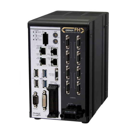
Omron fh-3 series Manuals
Manuals and User Guides for Omron fh-3 series. We have
12
Omron fh-3 series manuals available for free PDF download: Reference Manual, User Manual, Hardware Setup Manual, Hardware Manual, Setup Manual, Operation Manual
Omron fh-3 series Reference Manual (904 pages)
Vision Sensor FH/FZ5 Series
Brand:
Omron
| Category:
Accessories
| Size: 28 MB
Table of Contents
FH/FZ5 Manual Configuration
3
Conventions Used in this Manual
4
Terms and Conditions Agreement
5
Precautions for Correct Use
7
Precautions for Safe Use
7
Regulations and Standards
7
Safety Precautions
7
Table of Contents
9
Input Image
25
Camera Image Input
26
Settings Flow (Camera Image Input)
27
Camera Settings (Camera Image Input)
28
Select Camera (Camera Image Input)
28
Screen Adjustment Settings (Camera Image Input)
32
White Balance (Camera Image Input)
40
Calibration (Camera Image Input)
41
Additional Explanation (Camera Image Input)
45
Camera Image Input FH
46
Settings Flow (Camera Image Input FH)
47
Camera Selection (Camera Image Input FH)
48
Camera Settings (Camera Image Input FH)
48
Assigning Multiple Electronic Flashes to a Camera
55
Z341-E1
55
Screen Adjustment Settings (Camera Image Input FH)
56
White Balance (Camera Image Input FH)
66
Calibration (Camera Image Input FH)
68
Camera Image Input HDR
73
Vision System FH
73
Settings Flow (Camera Image Input HDR)
74
Camera Settings (Camera Image Input HDR)
75
HDR Settings (Camera Image Input HDR)
78
Bright Adjust Setting (Camera Image Input HDR)
80
Camera Image Input HDR Lite
81
Settings Flow (Camera Image Input HDR Lite)
82
Camera Settings (Camera Image Input HDR Lite)
83
HDR Settings (Camera Image Input HDR Lite)
83
Screen Adjust (Camera Image Input HDR Lite)
84
Camera Switching
85
Camera Selection (Camera Switching)
85
Additional Explanation (Camera Switching)
85
Measurement Image Switching
86
Parameter Settings (Measurement Image Switching)
86
Key Points for Test Measurement and Adjustment (Measurement Image Switching)
87
External Reference Tables (Measurement Image Switching)
88
Multi-Trigger Imaging
89
Multi-Trigger Imaging Task
92
Inspecting and Measuring
95
Search
97
Settings Flow (Search)
98
Model Registration (Search)
99
Region Setting (Search)
101
Detection Point (Search)
102
Reference Setting (Search)
103
Measurement Parameters (Search)
104
Output Parameters (Search)
106
Key Points for Test Measurement and Adjustment (Search)
106
Measurement Results for Which Output Is Possible (Search)
108
External Reference Tables (Search)
109
Flexible Search
112
Settings Flow (Flexible Search)
113
Model Registration (Flexible Search)
113
Region Setting (Flexible Search)
115
Measurement Parameters (Flexible Search)
116
Output Parameters (Flexible Search)
117
Key Points for Test Measurement and Adjustment (Flexible Search)
117
Measurement Results for Which Output Is Possible (Flexible Search)
119
External Reference Tables (Flexible Search)
119
Sensitive Search
121
Settings Flow (Sensitive Search)
121
Model Registration (Sensitive Search)
122
Region Setting (Sensitive Search)
125
Detection Point (Sensitive Search)
125
Reference Setting (Sensitive Search)
126
Measurement Parameters (Sensitive Search)
128
Output Parameters (Sensitive Search)
129
Key Points for Test Measurement and Adjustment (Sensitive Search)
129
Measurement Results for Which Output Is Possible (Sensitive Search)
131
External Reference Tables (Sensitive Search)
132
ECM Search
134
Settings Flow (ECM Search)
135
Model Registration (ECM Search)
136
Error Model Registration (ECM Search)
139
Region Setting (ECM Search)
139
Detection Point (ECM Search)
140
Reference Setting (ECM Search)
141
Measurement Parameters (ECM Search)
142
Output Parameters (ECM Search)
143
Key Points for Test Measurement and Adjustment (ECM Search)
143
When Using Measurement Results Externally (ECM Search)
144
External Reference Tables (ECM Search)
145
EC Circle Search
147
Settings Flow (EC Circle Search)
148
Circle Setting (EC Circle Search)
149
Region Setting (EC Circle Search)
150
Reference Setting (EC Circle Search)
150
Color Specification (EC Circle Search)
151
Measurement Parameters (EC Circle Search)
152
Output Parameters (EC Circle Search)
154
Key Points for Test Measurement and Adjustment (EC Circle Search)
154
Measurement Results for Which Output Is Possible (EC Circle Search)
155
External Reference Tables (EC Circle Search)
156
Shape Search II
158
Settings Flow (Shape Search II)
159
Model Registration (Shape Search II)
160
Region Setting (Shape Search II)
161
Detection Point (Shape Search II)
162
Reference Setting (Shape Search II)
163
Measurement Parameters (Shape Search II)
164
Output Parameters (Shape Search II)
166
Key Points for Test Measurement and Adjustment (Shape Search II)
166
Measurement Results for Which Output Is Possible (Shape Search II)
167
External Reference Tables (Shape Search II)
168
Shape Search III
170
Settings Flow (Shape Search III)
171
Model (Shape Search III)
172
Region Setting (Shape Search III)
178
Detection Point (Shape Search III)
179
Reference Setting (Shape Search III)
180
Measurement Parameter (Shape Search III)
181
Advertisement
Omron fh-3 series User Manual (882 pages)
Vision Sensor Vision System
Brand:
Omron
| Category:
Controller
| Size: 24 MB
Table of Contents
FH/FZ5 Manual Configuration
3
Conventions Used in this Manual
3
Definitions of Basic Terms
4
Table of Contents
9
Terms and Conditions Agreement
15
Meanings of Signal Words
17
Precautions for Safe Use
19
Precautions for Correct Use
20
1 Before Operation
23
Overview
24
Basic Mechanism for Measurements
24
Support for a Variety of Scenes and Measurement Lines
25
Flow of Application
27
Windows
29
Types of Windows
29
Overview of Window Navigation
30
Main Window (Layout 0): Adjustment Window (Default)
31
Main Window (Layout 1): Run Window (Default)
37
Menu List
38
Checking the System Configuration
40
System Configuration
40
Basic Configuration Models
41
Functional Comparison between the FH-Series and FZ5-Series Controllers
44
Saving Settings before Turning off the Power and Restarting
45
Restarting the Controller: [System Restart]
45
Turning off the LCD
46
Initializing the Controller
47
Initializing the Controller: [System Initialization]
47
2 Setting Scenes (Measurement Flows)
49
What Is a Scene
50
Example of a Scene
51
What Is a Scene Group
53
Creating a Scene
54
Editing Processing Units in Scenes
55
Displaying and Checking Processing Branches in a Scene
58
Changing the Scene or Scene Group
62
Changing the Scene
62
Changing Scene Groups
62
Editing Scenes
64
Copying Scenes
64
Deleting Scenes
64
Renaming a Scene and Adding a Description
65
Editing Scene Groups
66
Copying and Deleting Scene Groups
66
Changing the Scene Group Name
67
3 Performing Test Measurement/Starting Operation
69
Adjustment Windows and Run Windows
70
Main Window (Layout 0): Adjustment Window (Default)
70
Main Window (Layout 1): Run Window (Default)
71
Main Window (Layout 1): Changing to the Run Window
71
Main Window (Layout 1): Changing to the Adjustment Window
71
Preparing the Controller and Cameras
72
Camera Setup
72
Preparing a Controller
73
Adjusting the Camera
74
Intelligent Camera (with Lighting)
75
Executing Test Measurements
76
Key Points for Adjustment
77
Stabilizing Measurements
77
Shortening Processing Time
78
Arranging Windows
80
Arranging Window Elements (Layout Modification)
80
Setting the Behavior of Output Signals for each Layout (Layout Settings)
92
Changing Layout Numbers in the Main Window
92
Troubleshooting
93
Arranging the Window Display
94
Changing the Image Mode and Other Display Contents
94
Custom Dialogs
96
Flow of Use
96
Custom Dialog Tool
97
Launching Your Custom Dialog Box
110
Useful Functions for Operation
111
Remeasuring Saved Images
111
Improving Adjustment Efficiency
112
Changing Judgement Conditions Without Stopping Measurement
113
Changing Regions as a Batch [Shift Area]
114
Monitoring Measurement Value Trends
114
Logging Measurement Values and Measurement Images
115
Analyzing Logged Data
123
Clearing Measurement Results
124
Clearing Saved Images
125
Capturing Screen Images
125
Using the Operation Log
127
Operation Log Format
129
Saving Data to an External Device
130
Omron fh-3 series User Manual (582 pages)
Vision Sensor
Brand:
Omron
| Category:
Machine Vision Systems
| Size: 26 MB
Table of Contents
Fh-1£££/Fh
3
Intended Audience
3
Applicable Products
3
Relevant Manuals
4
Manual Structure
6
Page Structure
6
Special Information
7
Z365-E1
8
Table of Contents
9
Terms and Conditions Agreement
17
Warranty, Limitations of Liability
17
Application Considerations
18
Disclaimers
18
Safety Precautions
20
Symbols and the Meanings for Safety Precautions Described in this Manual
20
Meanings of Alert Symbols
20
Warning
21
Precautions for Safe Use
22
Condition of the Fitness of OMRON Products
22
Installation Environment (FH Series)
22
Installation Environment (FHV Series)
23
Power Supply and Wiring (FH Series)
23
Power Supply and Wiring (FHV Series)
23
Grounding (FH Series)
24
Mounting (FHV Series)
25
Others (FH Series)
25
Others (FHV Series)
26
Precautions for Correct Use
27
Installation and Storage Sites (FH-1000/2000/3000/5000 Series)
27
Installation and Storage Sites (FH-L Series)
27
Installation and Storage Sites (FHV Series)
27
Orientation of Product
28
Ambient Temperature
28
Noise Resistance
28
Component Installation and Handling (FH Series)
28
Component Installation and Handling (FHV Series)
29
Maintenance (FH Series)
29
Maintenance (FHV Series)
29
Communications with Upper Device
30
Failsafe Measures
30
Connecting the Sensor Controller and Monitor with a Switcher and Splitter (FH Series)
30
Warm-Up (FHV Series)
30
Camera Installation (FHV Series)
30
Beam (FHV Series)
31
Others (FHV Series)
31
LED Safety (FHV Series)
31
Regulations and Standards
33
All Series
33
FH-1000/2000/3000/5000 Series
33
FH-L Series
34
FHV Series
35
Related Manuals
36
Terminology
39
Revision History
44
Sections in this Manual
45
Section 1 Overview
48
Checking the System Configuration
48
System Configuration
48
Functional Comparison between the FH-Series and FHV-Series Controllers
49
Functional Comparison between the FH-Series and FHV-Series Con- Trollers
49
Flow of Application
52
Features
55
Section 2 Features
56
Basic Mechanism for Measurements
56
Support for a Variety of Scenes and Measurement Lines
58
Basic Operations
61
Section 3 Basic Operations
62
Preparing the Controller and Cameras
62
Camera Setup
62
Preparing the Controller
64
Adjusting the Camera
64
Basic Knowledge about Operations
66
Inputting Values
66
Inputting Text
66
Selecting Files and Folders
69
Available Operations in Select File Window
71
Using the Zoom Function
73
Setting Figures
73
Changing the Image Mode and Other Display Contents
81
Changing the Display Ratio
82
Checking System Information [System Information]
84
Checking the Memory Consumption and Percentage of Memory Used
88
Capturing Screen Images
89
Setting the Destination for Captured Images
89
Saving Captured Images
89
Saving Settings before Turning off the Power and Restarting
91
Saving the Setting to the Controller [Data Save]
91
Device Information Storage Tool
91
Restarting the Controller [System Restart]
93
Initializing the Controller [System Initialization]
96
Initializing with Sensor Controller
96
Initializing with Remote Operation
96
Updating Measurement Application [Version-Up]
98
By the Sensor Controller (FH Series)
98
By the Sensor Controller (FHV Series)
103
By the Remote Operation
105
Section 4 Setting the Controller
110
Setting the Controller
110
Selecting Language [Startup Settings]
110
Setting the Status at Startup [Startup Settings]
111
Setting Communication [Startup Settings]
114
Setting Operation Mode [Startup Settings]
119
Setting the Operation Mode
119
Parallel Processing
135
Checking the Camera Connections [Camera Connection]
146
Setting the Trigger Delay [Inter-Camera Setting]
147
Trigger Delay Setting
147
Setting the SHTOUT Signal [Output Signal Settings]
150
Setting the Conditions Related to Communications
153
Setting Date/Time [Date/Time Settings]
154
Setting Fan Control [Fan Control Setting]
156
Setting the Pulse Width for the STEP Input Detection [STEP Signal Filter Setting]
157
Setting the Pulse Width for the STEP Input Detection [STEP Sig- Nal Filter Setting]
157
Setting Encoder Trigger [Encoder Trigger Setting]
158
Setting Network Drive [Network Drive Setting]
160
Advertisement
Omron fh-3 series User Manual (582 pages)
Brand:
Omron
| Category:
Machine Vision Systems
| Size: 28 MB
Table of Contents
Table of Contents
16
Sections in this Manual
17
Contents
17
Terms and Conditions Agreement
24
Warranty, Limitations of Liability
24
Safety Precautions
26
Precautions for Safe Use
28
Precautions for Correct Use
33
Regulations and Standards
39
All Series
39
FH-1000/2000/3000/5000 Series
39
FH-L Series
40
FHV Series
41
FZ5 Series/Fz5-L Series
41
Revision History
42
Overview
43
Checking the System Configuration
44
System Configuration
44
Functional Comparison between the FH-Series, FHV-Series and FZ5-Series Controllers
45
Flow of Application
49
Features
51
Basic Mechanism for Measurements
52
Support for a Variety of Scenes and Measurement Lines
54
Basic Operations
57
Preparing the Controller and Cameras
58
Camera Setup
58
Preparing a Controller
60
Adjusting the Camera
61
Basic Knowledge about Operations
62
Inputting Values
62
Inputting Text
63
Selecting Files and Folders
66
Available Operations in Select File Window
69
Using the Zoom Function
70
Setting Figures
71
Changing the Image Mode and Other Display Contents
80
Changing the Display Ratio
81
Checking System Information
83
Checking the Memory Consumption and Percentage of Memory Used
87
Capturing Screen Images
88
Saving Settings before Turning off the Power and Restarting
90
Saving the Setting to the Controller [Data Save]
90
Device Information Storage Tool
91
Restarting the Controller: [System Restart]
93
Initializing the Controller
95
Turning off the LCD
97
Turning off the LCD [LCD OFF]
97
Restoring Power to the LCD
97
Setting the Controller
99
Selecting Language [Startup Settings]
100
Setting the Status at Startup [Startup Settings]
101
Setting Communication [Startup Settings]
104
Setting Operation Mode [Startup Settings]
110
Setting the Operation Mode
111
Parallel Processing
127
Checking the Camera Connections: [Camera Connection]
137
Setting the Trigger Delay [Inter-Camera Setting]
138
Setting the SHTOUT Signal [Output Signal Settings]
141
Setting the Conditions Related to Communications
144
Setting Date/Time [Date/Time Settings]
145
Setting Fan Control [Fan Control Setting]
147
Setting]
147
Setting the Pulse Width for the STEP Input Detection [STEP Signal Filter Setting]
148
Setting Encoder Trigger [Encoder Trigger Setting]
149
Setting Network Drive [Network Drive Setting]
151
Setting Screen Capture [Screen Capture Setting]
155
Setting the Conditions that Are Related to Operation During Measurement [Measurement Conditions]
156
Setting Logging Conditions [Logging Setting]
158
Setting Operation Log [Operation Log Setting]
159
Setting the Operation at Error [Error Operation Setting]
160
Omron fh-3 series User Manual (647 pages)
for Communication Settings
Brand:
Omron
| Category:
Machine Vision Systems
| Size: 14 MB
Table of Contents
Fh-3£££/Fh
3
Intended Audience
3
Applicable Products
3
Relevant Manuals
4
Manual Structure
6
Page Structure
6
Special Information
7
Conventions Used in this Manual
7
Table of Contents
9
Z342-E1
12
Terms and Conditions Agreement
13
Safety Precautions
15
Precautions for Safe Use
16
Precautions for Correct Use
17
Regulations and Standards
18
Related Manuals
19
Revision History
21
Sections in this Manual
23
Overview
25
Introduction
26
Confirming the System Configuration
27
System Configuration
27
Communicating with an External Device
28
Basic Control Operations of the Sensor Controller
28
Communications between the Sensor Controller and an External Device
29
Control Methods for the Sensor Controller
31
Communication Protocols for Communicating with the Sensor Controller
33
Saving Sensor Controller Data to an External Device
35
Control Methods Using an External Device
37
Control with Control Signals and Status Signals
37
Command/Response Method
40
Data Output after Measurements
41
Setting Procedures for Communications
52
Communications Setup Procedures
52
Communications Protocols and Communications Modules
53
Differences in Specifications Based on the Communications Protocol
55
Differences in Specifications Based on the Communications Pro- Tocol
55
List of Supported Signals by Communications Protocol
55
Restrictions When Using Different Communication Protocols Simultaneously
57
Restrictions When Using Different Communication Protocols Simulta- Neously
57
Restrictions in Communication Protocols by Operation Mode
57
Models Being Compatible with Communication Protocol
58
Ethercat Connections
66
Introduction to Ethercat
66
Structure of CAN Application Protocol over Ethercat (Coe)
69
Ethercat Slave Information Files (ESI Files)
70
Transitions of Communications States
71
Process Data Objects (Pdos)
72
Service Data Objects (Sdos)
75
Communications between Master and Slaves for Ethercat
76
Communication Method of FH Sensor Controller Connected by Ethercat
77
Communications Settings
82
Communications Module Settings (Startup Settings)
84
Communication Specifications Settings
85
Output Data Settings (Processing Item Registration)
90
Setting Output Data (Numerical Values/Character Strings)
93
Ethercat Network Configuration Settings
100
Communication Test
101
I/O Ports by Area (PDO Mapping) and Memory Allocation
102
I/O Signals
108
Measurement Results for Which Output Is Possible (Fieldbus Data Output)
112
Command List
114
Measurement Trigger Input
117
Command Response Processing
118
Data Output
120
Timing Chart
123
Ethercat Troubleshooting
127
Sysmac Error Status
129
Sysmac Device Features
147
Object Dictionary
150
Omron fh-3 series User Manual (384 pages)
Vision Sensor FH Series; FZ5 Series
Brand:
Omron
| Category:
Machine Vision Systems
| Size: 26 MB
Table of Contents
Structure of FH/FZ5 Manuals
3
Conventions Used in this Manual
4
Definitions of Basic Terms
5
Table of Contents
9
Terms and Conditions Agreement
15
Safety Precautions
17
Precautions for Safe Use
19
Precautions for Correct Use
22
Regulations and Standards
25
1 Before Operation
29
Overview
30
Basic Mechanism for Measurements
30
Support for a Variety of Scenes and Measurement Lines
31
Flow of Application
33
Windows
35
Types of Windows
35
Overview of Window Navigation
36
Main Window (Layout 0): Adjustment Window (Default)
37
Main Window (Layout 1): Run Window (Default)
43
Menu List
44
Checking the System Configuration
46
System Configuration
46
Functional Comparison between the FH-Series and FZ5-Series Controllers
47
Saving Settings before Turning off the Power and Restarting
51
Restarting the Controller: [System Restart]
51
Turning off the LCD
52
Accuracy
53
Initializing the Controller
54
Initializing the Controller: [System Initialization]
54
2 Setting Scenes (Measurement Flows)
55
What Is a Scene
56
Example of a Scene
57
What Is a Scene Group
59
Creating a Scene
60
Editing Processing Units in Scenes
61
Displaying and Checking Processing Branches in a Scene
64
Changing the Scene or Scene Group
68
Changing the Scene
68
Changing Scene Groups
68
Editing Scenes
70
Copying Scenes
70
Deleting Scenes
70
Renaming a Scene and Adding a Description
71
Editing Scene Groups
72
Copying and Deleting Scene Groups
72
Changing the Scene Group Name
73
3 Performing Test Measurement/Starting Operation
75
Adjustment Windows and Run Windows
76
Main Window (Layout 0): Adjustment Window (Default)
76
Main Window (Layout 1): Run Window (Default)
77
Main Window (Layout 1): Changing to the Run Window
77
Main Window (Layout 1): Changing to the Adjustment Window
77
Preparing the Controller and Cameras
78
Camera Setup
78
Preparing a Controller
80
Adjusting the Camera
80
Executing Test Measurements
81
Key Points for Adjustment
82
Stabilizing Measurements
82
Shortening Processing Time
83
Arranging Windows
85
Arranging Window Elements (Layout Modification)
85
Setting the Behavior of Output Signals for each Layout (Layout Settings)
100
Changing Layout Numbers in the Main Window
100
Troubleshooting
101
Arranging the Window Display
102
Changing the Image Mode and Other Display Contents
102
Custom Dialogs
105
Flow of Use
105
Custom Dialog Tool
106
Launching Your Custom Dialog Box
117
Useful Functions for Operation
118
Remeasuring Saved Images
118
Improving Adjustment Efficiency
119
Changing Judgement Conditions Without Stopping Measurement
120
Changing Regions as a Batch [Shift Area]
121
Monitoring Measurement Value Trends
122
Logging Measurement Values and Measurement Images
122
Analyzing Logged Data
134
Clearing Measurement Results
136
Clearing Saved Images
136
Capturing Screen Images
136
Checking the Memory Consumption and Percentage of Memory Used
138
Using the Operation Log
139
Operation Log Format
141
Saving Data to an External Device
142
Omron fh-3 series Hardware Setup Manual (260 pages)
Vision Sensor
Brand:
Omron
| Category:
Industrial Equipment
| Size: 48 MB
Table of Contents
Introduction
3
Intended Audience
3
Applicable Products
3
Relevant Manuals
4
Manual Structure
6
Page Structure
6
Special Information
7
Sections in this Manual
9
Table of Contents
10
Terms and Conditions Agreement
14
Warranty, Limitations of Liability
14
Application Considerations
15
Disclaimers
15
Safety Precautions
16
Precautions for Safe Use
18
Precautions for Correct Use
21
Regulations and Standards
24
All Series
24
FH-1000 and FH-3000 Series
25
FH-L Series
26
FZ5 and FZ-L Series
27
Related Manuals
28
Terminology
29
Revision History
33
Confirm the Package
35
Sensor Controller
36
FH-3 Series
36
10 / FH-3-10 Series
36
FH-1-20 / FH-3-20 Series
37
FH-L Series
37
FH-L-10 Series
38
FZ5-12 / FZ5-11 / FZ5-60 / FZ5-8 Series
38
FZ5-L35 Series
39
FZ5-L35-10 Series
39
Sold Separately
40
Cameras and Related
40
Monitor
42
Lighting and Lighting Controller
42
Accessories
43
Cable
44
Software
46
Overview of System
48
Basic System of Measurement
48
FH-1000/FH-3000 Series
50
FH-L Series
51
FZ5 Series
51
FZ5-L Series
52
System Configuration
53
FH-1000/FH-3000 Series
53
FH-L Series
54
Omron fh-3 series Hardware Manual (254 pages)
vision sensor
Brand:
Omron
| Category:
Accessories
| Size: 23 MB
Table of Contents
Introduction
3
Intended Audience
3
Applicable Products
3
Relevant Manuals
4
Manual Structure
6
Page Structure
6
Special Information
7
Sections in this Manual
9
Table of Contents
10
Terms and Conditions Agreement
14
Warranty, Limitations of Liability
14
Safety Precautions
16
Precautions for Safe Use
18
Precautions for Correct Use
21
Regulations and Standards
24
All Series
24
FH-1000 and FH-3000 Series
25
FH-L Series
26
FZ5 and FZ-L Series
27
Related Manuals
28
Terminology
29
Revision History
33
Z366-E1
33
Confirm the Package
35
Sensor Controller
36
10 / FH-3 -10 Series
36
FH-3 Series
36
20 / FH-3 -20 Series
37
FH-L Series
37
FH-L -10 Series
38
FZ5-60 Series
38
FZ5-L35 -10 Series
39
FZ5-L35 Series
39
Sold Separately
40
Cameras and Related
40
Monitor
42
Lighting and Lighting Controller
42
Accessories
43
Cable
44
Software
46
Overview of System
48
Basic System of Measurement
48
FH-1000/FH-3000 Series
50
FH-L Series
51
FZ5 Series
51
FZ5-L Series
52
System Configuration
53
FH-1000/FH-3000 Series
53
FH-L Series
54
FZ5-600/FZ5-1100 Series
55
FZ5-L Series
56
Omron fh-3 series Setup Manual (248 pages)
Vision System
Brand:
Omron
| Category:
Industrial Equipment
| Size: 22 MB
Table of Contents
Intended Audience
3
Applicable Products
3
Relevant Manuals
4
Manual Structure
6
Page Structure
6
Special Information
7
Sections in this Manual
9
Table of Contents
10
Terms and Conditions Agreement
14
Warranty, Limitations of Liability
14
Application Considerations
15
Disclaimers
15
Safety Precautions
17
Symbols and the Meanings for Safety Precautions Described in this Manual
17
Meanings of Alert Symbols
17
Warning
18
Precautions for Safe Use
19
Condition of the Fitness of OMRON Products
19
Installation Environment
19
Power Supply and Wiring
20
Grounding
20
Others
20
Precautions for Correct Use
22
Installation and Storage Sites (FH-1000/2000/3000/5000 Series)
22
Installation and Storage Sites (FH-L Series)
22
Orientation of Product
22
Ambient Temperature
22
Noise Resistance
23
Component Installation and Handling
23
Maintenance
23
Communications with Upper Device
23
Failsafe Measures
24
Connecting the Sensor Controller and Monitor with a Switcher and Splitter
24
Regulations and Standards
25
All Series
25
FH-1000/2000/3000/5000 Series
25
FH-L Series
26
Related Manuals
28
Terminology
29
Sensor Controller
29
Revision History
34
Sensor Controller
36
FH-2£££/FH-3£££/FH-5£££ Series
36
10/FH-2£££-10/FH-3£££-10/FH-5£££-10 Series
36
FH-1£££-20/FH-2£££-20/FH-3£££-20/FH-5£££-20 Series
37
FH-L£££ Series
37
FH-L£££-10 Series
37
Sold Separately
39
FH Application Software
39
Cameras and Related
39
Monitor
41
Omron fh-3 series Hardware Setup Manual (244 pages)
Vision System
Brand:
Omron
| Category:
Accessories
| Size: 14 MB
Table of Contents
Intended Audience
3
Applicable Products
3
Relevant Manuals
4
Manual Structure
6
Page Structure
6
Special Information
7
Table of Contents
9
Terms and Conditions Agreement
13
Warranty, Limitations of Liability
13
Application Considerations
14
Disclaimers
14
Safety Precautions
16
Symbols and the Meanings for Safety Precautions Described in this Manual
16
Meanings of Alert Symbols
16
Warning
17
Precautions for Safe Use
18
Condition of the Fitness of OMRON Products
18
Installation Environment
18
Power Supply and Wiring
19
Grounding
19
Others
19
Precautions for Correct Use
21
Installation and Storage Sites (FH-1000/2000/3000/5000 Series)
21
Installation and Storage Sites (FH-L Series)
21
Orientation of Product
21
Ambient Temperature
21
Noise Resistance
22
Component Installation and Handling
22
Maintenance
22
Communications with Upper Device
22
Failsafe Measures
23
Connecting the Sensor Controller and Monitor with a Switcher and Splitter
23
Regulations and Standards
24
All Series
24
FH-1000/2000/3000/5000 Series
24
FH-L Series
25
Related Manuals
27
Terminology
28
Sensor Controller
28
Revision History
33
Sections in this Manual
35
Sensor Controller
38
FH-2£££/FH-3£££/FH-5£££ Series
38
10/FH-2£££-10/FH-3£££-10/FH-5£££-10 Series
38
FH-1£££-20/FH-2£££-20/FH-3£££-20/FH-5£££-20 Series
39
FH-L£££ Series
39
FH-L£££-10 Series
39
Sold Separately
41
Cameras and Related
41
Monitor
43
Lighting and Lighting Controller
44
Accessories
45
Cable
46
Software
48
Omron fh-3 series Hardware Setup Manual (244 pages)
Vision Sensor
Brand:
Omron
| Category:
Accessories
| Size: 18 MB
Table of Contents
Table of Contents
10
Introduction
3
Intended Audience
3
Applicable Products
3
Fh-L
3
Relevant Manuals
4
Manual Structure
6
Page Structure
6
Special Information
7
Sections in this Manual
9
Table of Contents
10
Terms and Conditions Agreement
14
Warranty, Limitations of Liability
14
Application Considerations
15
Disclaimers
15
Safety Precautions
17
Symbols and the Meanings for Safety Precautions Described in this Manual
17
Meanings of Alert Symbols
17
Warning
18
Precautions for Safe Use
20
Condition of the Fitness of OMRON Products
20
Installation Environment
20
Power Supply and Wiring
21
Grounding
21
Others
21
Precautions for Correct Use
23
Installation and Storage Sites (FH-2000/FH-5000 Series)
23
Installation and Storage Sites (FH-L Series)
23
Orientation of Product
23
Ambient Temperature
23
Noise Resistance
24
Component Installation and Handling
24
Maintenance
24
Communications with Upper Device
24
Connecting the Sensor Controller and Monitor with a Switcher and Splitter
25
Failsafe Measures
25
Regulations and Standards
26
All Series
26
FH-2000/FH-5000 Series
26
FH-L Series
27
Related Manuals
28
Terminology
29
Revision History
33
Fh-L£££-10
37
Sold Separately
39
FH Application Software
39
Cameras and Related
39
Monitor
41
Lighting and Lighting Controller
42
Accessories
43
Cable
44
Software
46
Overview of FH Series
49
Overview of System
50
Basic System of Measurement
50
FH-2000/FH-5000 Series
52
FH-L Series
53
System Configuration
54
FH-2000/FH-5000 Series
54
FH-L Series
55
Flow of Use Procedure
56
Configuration
59
Sensor Controller
61
FH-2000/FH-5000 Series
61
FH-L Series
69
Camera
75
High-Speed Digital CMOS Camera (FH-S Camera Series)
75
Digital CMOS Camera
80
Digital CCD Camera: FZ-S Camera Series
83
High-Speed Digital CCD Camera: FZ-SH Camera Series
85
Small Digital CCD Cameras: FZ-S Camera Series
86
Intelligent Compact Digital CMOS Camera: FZ-S Camera Series
89
Camera Cable
92
Camera Cable and Right-Angle Camera Cable
92
Bend Resistant Camera Cable and Bend Resistant Right-Angle Camera Cable
93
Long-Distance Camera Cable and Long-Distance Right-Angle Camera Cable
94
Cable Connection Table
95
Cable Extension Units
99
Lens
103
C-Mount Lens for 1/3-Inch Image Sensor (SV-V Series)
103
C-Mount Lens for 2/3-Inch Image Sensor (SV-H Series)
104
C-Mount Lens for 1-Inch Image Sensor (VS-H1 Series)
105
C-Mount Lens for 4/3-Inch Image Sensor (VS-LLD Series)
106
M42-Mount Lens for Large Image Sensor (VS-L/M42-10 Series)
107
Lenses for Small Camera (FZ-LES Series)
107
Vibration and Shock Resistant C-Mount Lens for 2/3-Inch Image Sensor (VS-MCA Series)
108
Vibration and Shock Resistant C-Mount Lens for 1-Inch Image Sensor (VS-MCH Series)
110
Vibration and Shock Resistant C-Mount Lens for 1-Inch Image Sensor (VS-MCH1 Series)
113
Vibration and Shock Resistant M42-Mount Lens for 1.8-Inch Image Sensor (VS-MCL/ M42-10 Series)
116
High-Resolution Telecentric Lens for C-Mount Lens for 2/3-Inch Image Sensor (VS-TCH Series)
118
High-Resolution Telecentric Lens for C-Mount Lens for 1.1-Inch Image Sensor (VS-TEV Series)
120
Extension Tubes
121
Meaning of Optical Chart
122
Touch Panel Monitor and Cable
138
LCD and Cable
144
Sysmac Studio
147
Handling and Installation Environment
149
All Series
150
FH-2000/FH-5000 Series
152
FH-L Series
153
All Series
156
When Turning on and off
156
Setup and Wiring
156
FH-2000/FH-5000 Series
157
Fail-Safe Measures
158
Sensor Controller Installation
159
All Series
159
FH-2000/FH-5000 Series
159
FH-L Series
165
Setup Touch Panel Monitor or Monitor
175
FH-2000/FH-5000 Series
175
All Series
175
FH-L Series
176
Camera Installation
177
All Series
177
FH-2000/FH-5000 Series
178
Insert/Remove SD Memory Card or USB Flash Drive
181
Common in All Series
181
Simulation Software
182
Use by Connecting Software
182
FZ_FH Remote Operation Tool
182
Sysmac Studio FH Tool
182
Omron fh-3 series Operation Manual (176 pages)
Vision System, for Sysmac Studio
Brand:
Omron
| Category:
Industrial Equipment
| Size: 5 MB
Table of Contents
Fh-1£££/Fh
3
Intended Audience
3
Applicable Products
3
Relevant Manuals
4
Manual Structure
6
Page Structure
6
Special Information
7
Table of Contents
9
Terms and Conditions Agreement
13
Warranty, Limitations of Liability
13
Application Considerations
14
Disclaimers
14
Safety Precautions
16
Precautions for Safe Use
17
Precautions for Correct Use
18
Regulations and Standards
19
Related Manuals
20
Terminology
22
Revision History
23
Sections in this Manual
25
Overview
27
Supported Models
28
Project Management
29
Project Data
29
Project Data Handling in Different System Configurations
30
Basic Operations
35
Basic Design Flow 1
37
Basic Design Flow 2
37
Basic Design Flow 1
39
Basic Design Flow 2
39
Creating a New Project
41
Creating a New Project File from the Project Window
41
Adding FH/FHV Device to a Project
42
Deleting FH/FHV Device from a Project
43
Description of Screen Components
44
Application Window
44
Menu Bar
44
Toolbar
45
Multiview Explorer
45
Edit Pane
47
Toolbox
63
Basic Operations of Scene Data
65
Switching Scenes
65
Managing Scenes
66
Entering Scene Information
66
Searching for a Scene
67
Switching Scene Groups
67
Managing Scene Groups
67
Entering Scene Group Information
68
Basic Operations of Flow Editing
69
Adding a Processing Unit
69
Managing Processing Units
70
Searching for a Processing Unit
72
Function List
73
List of Functions Provided with the FH/FHV Tool
73
Comparison with FH Series Unit Functions
75
Comparison with FHV Series Unit Functions
76
Advertisement
Related Products
Omron fh series
Omron fh-l series
Omron FH-5050
Omron FHV7H-C004-H19-MC
Omron FHV7H-M063R-S09-R
Omron FHV7H-M063R-H06-R
Omron FHV7H-C016-H19-W
Omron FHV7H-C063R-S16-MC
Omron FHV7H-M016-H19-IR
Omron FHV7H-M063R-H06-IR
Omron Categories
Blood Pressure Monitor
Controller
Accessories
Switch
Inverter
More Omron Manuals
Login
Sign In
OR
Sign in with Facebook
Sign in with Google
Upload manual
Upload from disk
Upload from URL