Sign In
Upload
Manuals
Brands
Lenze Manuals
Inverter
I95AE411F
Lenze I95AE411F Manuals
Manuals and User Guides for Lenze I95AE411F. We have
3
Lenze I95AE411F manuals available for free PDF download: Commissioning Manual, Mounting And Switch-On Instructions
Lenze I95AE411F Commissioning Manual (472 pages)
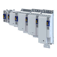
Servo Inverters
Brand:
Lenze
| Category:
Inverter
| Size: 4.98 MB
Table of Contents
Table of Contents
3
1 About this Document
15
Document Description
15
Further Documents
15
Notations and Conventions
16
2 Safety Instructions
17
Basic Safety Instructions
17
Application as Directed
17
Residual Hazards
18
3 Product Information
19
Identification of the Products
19
Product Codes
19
Nameplates
20
Features
21
4 Commissioning
27
Important Notes
27
Operating Interfaces
28
Engineering Tool »EASY Starter
29
Generate a Connection between Inverter and »EASY Starter
30
General Information on Parameter Setting
31
Addressing of the Parameters
31
Structure of the Parameter Descriptions
31
Parameter Overview Lists
31
Favourites
32
Configuring the "Favourites
32
Commissioning
35
Saving the Parameter Settings
36
Save Parameter Settings with »EASY Starter
36
5 Basic Setting
37
Device Name
37
Mains Voltage
37
Function Assignment of the Inputs and Outputs (Default Setting)
37
Motor Data
38
Select Motor from Motor Catalogue
39
Manual Setting of the Motor Data
41
Motor Control Mode
44
6 Technology Application (TA) Basic Settings
45
Kinematic Settings
46
Mass Inertia (Load/Motor)
46
Torque Feedforward Control
46
Motor/Encoder Mounting Direction
46
Motor/Encoder Gearbox Ratio
47
Motor/Encoder Feed Constant
49
Motor/Encoder Travel Ranges and Cycle Length
50
Virtual Mode
52
Motion Settings
53
Quick Stop
53
Halt
54
Following Error Monitoring
54
Target Position Detection
55
Motor/Encoder Standstill Detection
55
Conditioning of the Encoder Signal
55
Behaviour in the Event of Inverter Disable
56
Control Modes
57
Manual Jog (Inching Mode)
58
Homing
59
Homing Modes
61
Digital Input for Reference Switch
70
Motor/Encoder Behaviour after Mains Switching
70
Limitations
71
Torque Limits
71
Maximum Values for Travel Profiles
72
Hardware Limit Switches
73
Software Limit Switches
75
Safety Limits
76
Status Signals
78
Defining Control Sources
80
Source of Quick Stop
80
Source of Error Reset
80
Source of Digital Output 1
81
Source of Monitoring Signal
82
System Bus Communication
84
Inputs
84
Outputs
84
Master Value Output
85
Source of Touch Probe Time Stamp
86
Distribution of the Master Values by the Master
87
Example: System Bus Master Is Master Value Master
88
Example: System Bus Slave Is Master Value Master
89
Example: Using Time Stamp of Another Axis
90
7 Configuring the "Electronic Gearbox" TA
91
Control Settings
92
Interface
93
Control Signals
94
Status Signals
95
Simulation of the Interface
96
Assignment of Control Signals and Status Signals
97
Master Value Sources
99
System Bus
100
Feedback System for the Technology Application
101
Virtual Master
103
Simulation of the Virtual Master
110
Speed Via Analog Input 1
111
External Master Values
112
External Torque Limitation
115
Velocity Synchronization
117
Clutching
119
Clutching with Basic Speed
120
Connecting the Velocity Offset
122
Position Trimming
124
Signal Flow
127
8 Start, Stop and Rotating Direction Commands
129
Control Selection
129
9 Configure Position Control
130
Basic Setting
131
Following Error Detection and In-Position Detection
132
Interpolation
133
Operating Mode "Cia 402 Cyclic Sync Position Mode (Csp)
134
Default Mapping
134
Signal Flow
135
Control Commands and Status Information
137
Process Input Data (Cia 402 Objects)
138
Process Output Data (Cia 402 Objects)
139
Monitoring the Position Error
140
Position Detection with Touch Probe (TP)
141
Default Mapping
141
General Mode of Operation
142
Filtering of the Touch Probe Signal
142
Compensation of Runtime Delays
143
Touch Probe Control Word
144
Touch Probe Status Word
144
Extension for the Digital Inputs DI3 and DI4
145
Detected Time Stamp and Positions
145
Setpoint Diagnostics
146
10 Configure Speed Control
147
Basic Setting
147
Operating Mode "Cia 402 Velocity Mode (Vl)
148
Default Mapping
148
Signal Flow (Servo Control)
149
Signal Flow (V/F Characteristic Control)
151
Operating Mode "Cia 402 Cyclic Sync Velocity Mode (Csv)
153
Default Mapping
153
Signal Flow (Servo Control)
154
Signal Flow (V/F Characteristic Control)
156
Control Commands and Status Information
158
Process Input Data (Cia 402 Objects)
159
Process Output Data (Cia 402 Objects)
161
Monitoring the Speed Deviation
162
11 Configuring the Torque Control
163
Basic Setting
164
Torque Limits
165
Speed Limitation
166
Operating Mode "Cia 402 Cyclic Sync Torque Mode (Cst)
167
Default Mapping
167
Signal Flow
168
Control Commands and Status Information
170
Process Input Data (Cia 402 Objects)
171
Process Output Data (Cia 402 Objects)
173
Setpoint Diagnostics
174
12 Configuring the Feedback System
175
Configure Feedback System for Motor Control
176
General Settings
177
Resolver Settings
178
Resolver Error Compensation
180
Encoder Settings
182
Sincos Encoder
183
Sincos Absolute Value Encoder with HIPERFACE® Protocol
183
SSI Encoder
185
Evaluation of the Signal Quality
187
Detection of Changed Settings of the Feedback System
188
Diagnostics
188
Second Feedback System for the Techology Application
189
General Settings
189
Resolver Settings
190
Resolver Error Compensation
191
Encoder Settings
193
Sincos Encoder
194
Sincos Absolute Value Encoder with HIPERFACE® Protocol
194
SSI Encoder
196
Evaluation of the Signal Quality
198
Detection of Changed Settings of the Feedback System
199
Diagnostics
199
Encoder: Evaluation of Safely Speed and Position
200
Synchronous Motor: Pole Position Identification (PPI)
201
Monitoring the Pole Position Identification
202
Pole Position Identification (PPI) 360
203
Pole Position Identification (PPI) with Minimum Movement
207
Pole Position Identification (PPI) Without Movement
210
13 Configuring the Motor Control
212
Servo Control for Synchronous Motor (SC-PSM)
213
Required Commissioning Steps
213
Servo Control for Asynchronous Motor (SC-ASM)
214
Required Commissioning Steps
214
Sensorless Control for Synchronous Motor (SL-PSM)
214
V/F Characteristic Control for Asynchronous Motor (VFC Open Loop)
215
Required Commissioning Steps
215
Basic Setting
216
Define V/F Characteristic Shape
217
Linear V/F Characteristic
217
Square-Law V/F Characteristic
217
User-Definable V/F Characteristic
218
Activate Voltage Vector Control (Imin Controller)
219
Set Voltage Boost
221
Set Load Adjustment
222
Set Slip Compensation
222
Set Oscillation Damping
223
Optimising the Stalling Behaviour
224
Flying Restart Circuit
225
Parameterisable Motor Functions
227
DC Braking
227
Short-Circuit Braking
228
Holding Brake Control
229
Basic Setting
230
Brake Holding Load
231
Torque Feedforward Control
232
Manual Brake Control
232
Options for Optimising the Control Loops
233
Automatic Motor Identification (Energized)
233
Tuning of the Motor and the Speed Controller
234
Inverter Characteristic
236
Compensating for Inverter Influence
237
Extended Settings for Identification
238
Load Standard Inverter Characteristic
238
Motor Equivalent Circuit Diagram Data
239
Motor Control Settings
240
Speed Controller
240
Current Controller
243
ASM Field Controller
245
ASM Field Weakening Controller
246
ASM Field Weakening Controller (Extended)
246
PSM Field Weakening Controller
247
Imax Controller
248
Flying Restart Controller
248
Position Controller
249
Fine Adjustment of the Motor Model
250
Correction of the Stator Leakage Inductance (Lss)
251
Synchronous Motor (SM): Compensate Temperature and Current Influences
256
Asynchronous Motor (ASM): Identify Lh Saturation Characteristic
257
Estimate Optimum Magnetising Current
259
Parameterise Filter Elements in the Setpoint Path
260
Jerk Limitation
260
Notch Filter (Band-Stop Filter)
261
Motor Protection
264
Motor Overload Monitoring (I²*T)
264
Parameters for the Thermal Model
266
Speed-Dependent Evaluation of the Motor Current
268
UL 508-Compliant Motor Overload Monitoring
271
Motor Temperature Monitoring
272
Individual Characteristic for Motor Temperature Sensor
273
Overcurrent Monitoring
274
Motor Phase Failure Detection
274
Motor Speed Monitoring
275
Frequency and Speed Limitations
276
Testing the Motor Control
277
General Settings for Test Modes
277
Manual "Tension/Frequency" Test Mode
279
Manual "Current/Frequency" Test Mode
280
Manual "Current Pulse" Test Mode
281
14 O Extensions and Control Connections
283
Configure Digital Inputs
283
Configure Analog Inputs
285
Analog Input 1
285
Configure Digital Outputs
287
Digital Output 1
287
15 Configure Engineering Port
288
Basic Setting
289
NTP Server Addresses
290
Diagnostics
290
16 Configuring the Network
291
Device Profile Cia
292
Supported Operating Modes
292
Basic Setting
293
Process Input Data
293
Process Output Data
293
Commands for Device State Control
294
Switch on
295
Enable Operation
296
Activate Quick Stop
297
Pulse Inhibit
298
Reset Fault
299
Device States
300
Not Ready to Switch on
302
Switch-On Inhibited
303
Ready to Switch on
304
Switched on
305
Operation Enabled
306
Quick Stop Active
307
Fault Reaction Active
308
Trouble
309
Ethercat
310
Commissioning
311
Basic Setting and Options
314
Synchronisation with "Distributed Clocks" (DC)
314
Parameterising Additional Functions
314
Process Data Transfer
317
Standard Mapping
317
Dynamic (Free) Configuration
317
Further Communication Objects
317
Expert Settings
317
Parameter Data Transfer
318
Monitoring
318
Diagnostics
319
LED Status Display
319
Information on the Network
319
Ethercat Master Diagnostics
319
Error History Buffer
329
Device Identification
329
Profinet
330
Commissioning
331
Settings in the »EASY Starter
331
Restarting or Stopping the Communication
332
Settings in the Siemens »TIA Portal
332
Device Description File
333
Establishing a Connection to the »EASY Starter« Via PROFINET
333
Basic Setting and Options
334
Station Name and IP Configuration
334
Suppress Diagnostic Messages to the IO Controller
335
Process Data Transfer
335
Parameter Data Transfer
336
Monitoring
337
Diagnostics
339
LED Status Display
339
Information on the Network
339
Profisafe
341
Profienergy
341
Supported Commands
341
Supported Measured Values
341
Ethercat System Bus
342
Commissioning
344
Basic Setting and Options
345
Process Data Transfer
346
Standard Mapping
347
Process Output Data
347
Process Input Data
347
Monitoring
348
Diagnostics
349
LED Status Displays
349
Information on the Network
349
Device Identification
351
17 Device Functions
353
Optical Device Identification
353
Reset Parameters to Default
354
Saving/Loading the Parameter Settings
355
Enabling the Device
356
Restart Device
356
Restarting Extended Safety
356
Export Logbook
356
Delete Logbook Files
357
Activate Loaded Application
357
Uploading the Application
357
Inverter Control Word
358
Access Protection
358
Brand Protection
358
Switching Frequency Changeover
358
Device Overload Monitoring (I*T)
359
Heatsink Temperature Monitoring
360
Update Device Firmware
360
Manual Firmware Download with »EASY Starter (Firmware Loader)
360
17.16.1.1 Download Via Ethernet Connection
360
18 Additional Functions
361
Brake Energy Management
361
Use of a Brake Resistor
361
Manual Jog Parameters
362
Mains Failure Control
363
Oscilloscope Function
364
19 Safety Functions
373
Safe Torque off (STO)
374
Safe Emergency Stop (SSE)
376
Ramp Monitoring
377
Safe Stop 1 (SS1)
379
Safe Stop 2 (SS2)
382
Safe Operating Stop (SOS)
385
Safe Maximum Speed (SMS)
387
Safely-Limited Speed (SLS)
388
Safe Speed Monitor (SSM)
393
Safely Limited Increment (SLI)
394
Safe Direction (SDI)
396
Safely-Limited Position (SLP)
398
Position-Dependent Safe Speed (PDSS)
401
Mini-Homing
403
Safe Homing (SHOM)
404
Safe Cam (SCA)
408
Operation Mode Selector (OMS)
410
Enable Switch (ES)
413
Repair Mode Select (RMS)
414
Cascading (CAS)
416
Safe Network Interfaces
417
Fsoe Connection
417
Connection to the Applications
418
Inputs
418
Outputs
419
Internal Communication
419
Control Signals
419
Status Signals
421
Safe Parameter Setting
425
Safety Address
425
Parameter Set Information
425
Response Times
426
Diagnostics
429
LED Status Display
429
19.25.1.1 LED Status During Parameter Set Transfer
429
Error History Buffer
429
Diagnostic Parameters
431
20 Technical Data
432
Standards and Operating Conditions
432
Conformities/Approvals
432
Protection of Persons and Device Protection
432
EMC Data
432
Motor Connection
433
Environmental Conditions
433
Electrical Supply Conditions
433
3-Phase Mains Connection
434
Rated Data
434
3-Phase Mains Connection 480 V
436
Rated Data
436
21 Appendix
438
Parameter Attribute List
438
Glossary
471
Advertisement
Lenze I95AE411F Mounting And Switch-On Instructions (188 pages)
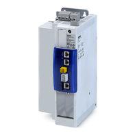
Cabinet inverter
Brand:
Lenze
| Category:
Inverter
| Size: 7.71 MB
Table of Contents
Deutsch
5
Table of Contents
5
Über dieses Dokument
8
Weiterführende Dokumente
8
Schreibweisen und Konventionen
9
Sicherheitshinweise
10
Grundlegende Sicherheitshinweise
10
Bestimmungsgemäße Verwendung
11
Vorhersehbarer Fehlgebrauch
11
Restgefahren
12
Produktinformation
14
Identifizierung der Produkte
14
Produktcodes
14
Typenschilder
15
Ausstattung
16
Lizenzinformation
22
Mechanische Installation
23
Vorbereitung
23
Abmessungen
25
Elektrische Installation
38
Wichtige Hinweise
38
EMV-Gerechte Installation
38
Anschluss nach UL
39
Wichtige Hinweise
39
Absicherungsdaten
42
Branch Circuit Protection (BCP)
42
DC Circuit Protection
45
Netzanschluss
46
1-Phasiger Netzanschluss 230/240 V
46
Anschlusspläne
46
Klemmendaten
47
Absicherungsdaten
47
3-Phasiger Netzanschluss 230/240 V
48
Anschlusspläne
48
Klemmendaten
49
Absicherungsdaten
50
Anschlusspläne
51
3-Phasiger Netzanschluss 400 V
52
Klemmendaten
52
Absicherungsdaten
53
3-Phasiger Netzanschluss 480 V
54
Anschlusspläne
54
Klemmendaten
55
Absicherungsdaten
56
Anschluss an das IT-Netz
57
Anschluss Versorgungsspannung
61
Anschluss Motorhaltebremse
62
Anschluss Bremswiderstand
64
Steueranschlüsse
66
Anschluss Motorgeber
67
Anschluss Lastgeber/Leitgeber
67
Anschluss Einkabeltechnologie (OCT) über HIPERFACE DSL
68
Netzwerke
70
Ethercat
70
Ethernet/Ip
71
Profinet
73
On-Board-Ethercat
74
Funktionale Sicherheit
75
Basic Safety - STO
76
Anschlussplan
77
Klemmendaten
78
Extended Safety
79
Anschlussplan
80
Klemmendaten
81
Inbetriebnahme
82
Wichtige Hinweise
82
Bedienschnittstellen
83
Engineering Tool "EASY Starter
84
Verbindung zwischen Inverter und "EASY Starter" Aufbauen
85
Inbetriebnahme Durchführen
85
Parametereinstellungen Speichern
86
Parametereinstellungen mit dem "EASY Starter" Speichern
86
Diagnose und Störungsbeseitigung
87
LED-Statusanzeigen
87
Technische Daten
88
Normen und Einsatzbedingungen
88
Konformitäten und Approbationen
88
Personenschutz und Geräteschutz
88
Angaben zur EMV
88
Motoranschluss
89
Umweltbedingungen
89
Netzbedingungen
89
1-Phasiger Netzanschluss 230/240 V
90
Bemessungsdaten
90
3-Phasiger Netzanschluss 230/240 V
91
Bemessungsdaten
91
3-Phasiger Netzanschluss 400 V
92
Bemessungsdaten
92
3-Phasiger Netzanschluss 480 V
94
Bemessungsdaten
94
Umwelthinweise und Recycling
96
English
97
About this Document
100
Further Documents
100
Notations and Conventions
101
Safety Instructions
102
Basic Safety Instructions
102
Application as Directed
103
Foreseeable Misuse
103
Residual Hazards
104
Product Information
106
Identification of the Products
106
Product Codes
106
Nameplates
107
Features
108
Licence Information
114
Mechanical Installation
115
Preparation
115
Dimensions
117
Electrical Installation
130
Important Notes
130
EMC-Compliant Installation
130
Connection According to UL
131
Important Notes
131
Fusing Data
134
Branch Circuit Protection (BCP)
134
DC Circuit Protection
137
Mains Connection
138
1-Phase Mains Connection 230/240 V
138
Connection Diagrams
138
Terminal Data
139
Fusing Data
139
3-Phase Mains Connection 230/240 V
140
Connection Diagrams
140
Terminal Data
141
Fusing Data
141
3-Phase Mains Connection 400 V
142
Connection Diagrams
142
Terminal Data
143
Fusing Data
144
3-Phase Mains Connection 480 V
145
Connection Diagrams
145
Terminal Data
146
Fusing Data
147
Connection to the IT System
148
Supply Voltage Connection
152
Motor Holding Brake Connection
153
Brake Resistor Connection
155
Control Connections
157
Motor Encoder Connection
158
Load Encoder/Master Encoder Connection
158
Connection of One Cable Technology (OCT) Via HIPERFACE DSL
159
Networks
161
Ethercat
161
Ethernet/Ip
162
Profinet
164
On-Board-Ethercat
165
Functional Safety
166
Basic Safety - STO
167
Connection Diagram
168
Terminal Data
169
Extended Safety
170
Connection Diagram
171
Terminal Data
172
Commissioning
173
Important Notes
173
Operating Interfaces
174
Engineering Tool "EASY Starter
175
Generate a Connection between Inverter and "EASY Starter
176
Commissioning
176
Saving the Parameter Settings
177
Save Parameter Settings with "EASY Starter
177
Diagnostics and Fault Elimination
178
LED Status Display
178
Technical Data
179
Standards and Operating Conditions
179
Conformities and Approvals
179
Protection of Persons and Device Protection
179
EMC Data
179
Motor Connection
180
Environmental Conditions
180
Electrical Supply Conditions
180
1-Phase Mains Connection 230/240 V
181
Rated Data
181
3-Phase Mains Connection 230/240 V
182
Rated Data
182
3-Phase Mains Connection 400 V
183
Rated Data
183
3-Phase Mains Connection 480 V
185
Rated Data
185
Environmental Notes and Recycling
187
Lenze I95AE411F Mounting And Switch-On Instructions (144 pages)
Brand:
Lenze
| Category:
Inverter
| Size: 6.21 MB
Table of Contents
Deutsch
5
Table of Contents
5
Über dieses Dokument
7
Dokumentbeschreibung
7
Weiterführende Dokumente
7
Schreibweisen und Konventionen
8
Sicherheitshinweise
9
Grundlegende Sicherheitshinweise
9
Bestimmungsgemäße Verwendung
9
Handhabung
10
Restgefahren
10
Lizenzinformation
11
Produktinformation
12
Identifizierung der Produkte
12
Produktcodes
12
Typenschilder
13
Ausstattung
14
Mechanische Installation
21
Abmessungen
21
Elektrische Installation
33
Wichtige Hinweise
33
Netzanschluss
36
Anschlusspläne
36
3-Phasiger Netzanschluss 400 V
38
Klemmendaten
38
Absicherungsdaten
40
3-Phasiger Netzanschluss 480 V
42
Anschlusspläne
42
Klemmendaten
43
Absicherungsdaten
44
Anschluss an das IT-Netz
47
Steueranschlüsse
51
Netzwerke
52
Profinet
52
Systembus Ethercat
53
Funktionale Sicherheit
54
Basic Safety - STO
55
Anschlussplan
55
Klemmendaten
56
Extended Safety
57
Anschlussplan
58
Klemmendaten
60
Inbetriebnahme
61
Wichtige Hinweise
61
Bedienschnittstellen
62
Engineering Tool "EASY Starter
63
Verbindung zwischen Inverter und "EASY Starter" Aufbauen
64
Allgemeines zur Parametrierung
65
Favoriten
65
Favoriten Konfigurieren
65
Inbetriebnahme Durchführen
66
Parametereinstellungen Speichern
67
Parametereinstellungen mit dem "EASY Starter" Speichern
67
Diagnose und Störungsbeseitigung
68
LED-Statusanzeigen
68
Technische Daten
69
Normen und Einsatzbedingungen
69
Konformitäten/Approbationen
69
Personenschutz und Geräteschutz
69
Angaben zur EMV
69
Motoranschluss
70
Umweltbedingungen
70
Netzbedingungen
70
3-Phasiger Netzanschluss 400 V
71
Bemessungsdaten
71
3-Phasiger Netzanschluss 480 V
73
Bemessungsdaten
73
English
75
About this Document
77
Document Description
77
Further Documents
77
Notations and Conventions
78
Safety Instructions
79
Basic Safety Instructions
79
Application as Directed
79
Handling
80
Residual Hazards
80
Licence Information
81
Product Information
82
Identification of the Products
82
Product Codes
82
Nameplates
83
Features
84
Mechanical Installation
91
Dimensions
91
Electrical Installation
103
Important Notes
103
Mains Connection
106
3-Phase Mains Connection 400 V
106
Connection Diagrams
106
Terminal Data
108
Fusing Data
110
3-Phase Mains Connection 480 V
112
Connection Diagrams
112
Terminal Data
113
Fusing Data
114
Connection to the IT System
117
Control Connections
121
Networks
122
Profinet
122
Ethercat System Bus
123
Functional Safety
124
Basic Safety - STO
125
Connection Diagram
125
Terminal Data
126
Extended Safety
127
Connection Diagram
128
Terminal Data
129
Commissioning
130
Important Notes
130
Operating Interfaces
131
Engineering Tool "EASY Starter
132
Generate a Connection between Inverter and "EASY Starter
133
General Information on Parameter Setting
134
Favourites
134
Configuring the "Favourites
134
Commissioning
135
Saving the Parameter Settings
136
Save Parameter Settings with "EASY Starter
136
Diagnostics and Fault Elimination
137
LED Status Display
137
Technical Data
138
Standards and Operating Conditions
138
Conformities/Approvals
138
Protection of Persons and Device Protection
138
EMC Data
138
Motor Connection
139
Environmental Conditions
139
Electrical Supply Conditions
139
3-Phase Mains Connection 400 V
140
Rated Data
140
3-Phase Mains Connection 480 V
142
Rated Data
142
Advertisement
Advertisement
Related Products
Lenze I95AE275F
Lenze I95AE311F
Lenze I95AE175F
Lenze I95AE315F
Lenze I95AE345F
Lenze I95AE375F
Lenze I95AE355F
Lenze I95AE222F
Lenze I95AE137D
Lenze I95AE175D
Lenze Categories
DC Drives
Control Unit
Inverter
Engine
Controller
More Lenze Manuals
Login
Sign In
OR
Sign in with Facebook
Sign in with Google
Upload manual
Upload from disk
Upload from URL