Table of Contents
Advertisement
Quick Links
Advertisement
Table of Contents

Related Manuals for Microscan MS-850


Summary of Contents for Microscan MS-850
- Page 1 MS-850 Raster Scanner User's Manual P/N 83-000850 Rev. H...
- Page 2 A copy of a purchase order with the amount of the charge must be received by Microscan, either by mail or by FAX, before any equipment is returned. Warrantable products are repaired or replaced at no charge and returned freight prepaid.
-
Page 3: Table Of Contents
Communications Commands ..........3-6 Protocol ................. 3-7 Operations Commands ...........3-10 Code Type Commands ............3-13 Output .................3-18 Setup ................3-21 Raster Setup ..............3-23 Diagnostics ..............3-24 Utilities Read Rate ..............4-4 Counters ............... 4-6 Trigger ................4-8 Master Label ..............4-9 MS-850 Raster Scanner User’s Manual... - Page 4 Appendix G — Operational Tips ........A-16 Appendix H — Bar Code Symbology .........A-17 Appendix I — Interface Standards ........A-18 Appendix J — Multidrop Communications ......A-19 Appendix K — Grounding and Shielding ......A-22 Appendix L — Glossary of Terms ........A-23 Index MS-850 Raster Scanner User’s Manual...
-
Page 5: About This Manual
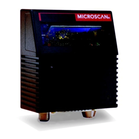
About the MS-850 Scanner The MS-850 is a compact, fixed-mount, industrial, raster scanner with a wide variety of user controls and intelligence including diagnostics, adjustable raster angles and speeds (up to 30 sweeps per second), adjustable spinning mirror speeds (from 350 to 1100 scans per second), and three programmable outputs. -
Page 6: Warning And Caution Summary
WARNING There are no user serviceable parts in the MS-850 scanner. Opening the scan head voids the Microscan Systems warranty and could expose the user to laser diode power of up to 7 mW. -
Page 7: Safety Labels
Safety Labels These Class II labels are located on the MS-850 scanner. AVO ID side EX PO SU R E L A S E R L IG H T IS E M ITT E D F R O M T H IS A P E R T U R E... - Page 8 Zum Anschluß an ein UL-zugelassenes Netzgerät der Klasse II mit 10 bis 28 Volt Gleichspannung und einer Leistung von 5 oder mehr Watt. Modelle für den europäischen Markt müssen eine entsprechende Stromversorgung der Klasse I oder II verwenden, die nach der Sicherheitsrichtlinie EN 60950 zertifi- ziert ist. viii MS-850 Raster Scanner User’s Manual...
-
Page 9: Technische Daten
Optimierungen am Bar Code Scanner vornimmt, muß der englischen Sprache mächtig sein und sollte fachkundigen Rat beim Hersteller oder Importeur einholen. Sollten Sie Fragen haben, kontaktieren Sie bitte Microscan Systems Inc. USA oder den entsprechenden europäischen Vertreter in Ihrem Land. - Page 10 MS-850 Raster Scanner User’s Manual...
-
Page 11: Quick Start
Step 10 Mount Scanner..........1-11 Step 11 Test Decode Rate with Moving Label ....1-12 Step 12 Increase the Number of Scans......1-13 This chapter provides step-by-step instructions for setting up and installing the MS-850 scanner. MS-850 Raster Scanner User’s Manual... -
Page 12: Step 1 Plan Scanning System
Chapter 1 Quick Start Step 1 Plan Scanning System Before installing the MS-850 scanner, sketch out a diagram of the scanning system, showing equipment, connector and cable types, and cable lengths. 3 programmable outputs To power supply M S - 850... -
Page 13: Step 2 Attach Cabling
Attach Cabling Step 2 Attach Cabling The MS-850 has 3 external connections: • Host, a 25-pin D-subminiature • Trigger, 4-pin • Power, 3-pin 25-pin host connector Power connector Trigger connector DB-25 DTE TO DB-25 DTE Connection Decoder Host Transmit Transmit... -
Page 14: Step 3 Establish Communications
Allow some time for the auto baud routine to test most of the combinations. You can watch this at the bottom of the dialog box. Once it has found it, it will change the host’s settings to match the scanner. The default settings for the MS-850 scanner are 9600 baud,... -
Page 15: Step 4 Configure Scanner
Note: When you save communications changes to the scanner, serial port settings are automatically matched. Note: You can check the scanner’s settings at any time by clicking SEND/RECV RECEIVE FROM SCANNER to receive the scanner’s current settings into ESP. MS-850 Raster Scanner User’s Manual... -
Page 16: Step 5 Position Scanner
The specular reflection zone is a narrow zone straight out from the scanner in which direct reflected light from a label can distort the scanner’s ability to dis- tinguish bars from spaces. For the MS-850 raster scanner, specular reflection is avoided by pitching labels at least 5°... -
Page 17: Step 6 Consider Read Range And Scan Width
Note The Approximate Scan Width At The Specific Distance The Labels Will Be Passing Through. Read range is the distance from the scanner in which a passing label can be read. For the MS-850, read range varies from inches (standard model) depending on label density and optical version of scanner. -
Page 18: Step 7 Determine Raster Height And Sweep Rate
If you know raster height, along with scan width, read range, and the speed the labels will be moving through the readable zone, you can determine the raster sweep rate by using the formula in Appendix E — “Formulas for Number of Decodes.” Direction of travel Scanner Raster height MS-850 Raster Scanner User’s Manual... -
Page 19: Step 8 Set Raster Height And Sweep Rate
Raster Sweep is the number of times the raster beam traverses its arc, up or down, in a second. Slower settings are generally preferred since they will produce more reads. Appendix E — “Formulas for Number of Decodes.” MS-850 Raster Scanner User’s Manual... -
Page 20: Step 9 Test Decode Rate With Static Label
Appendix E — “Formulas for Number of Decodes.” Note Variations between labels are common. For this reason, the greater number of sample labels you test, the more likely you are to achieve optimum decode rates. 1-10 MS-850 Raster Scanner User’s Manual... -
Page 21: Step 10 Mount Scanner
Mount Scanner Step 10 Mount Scanner The MS-850 scanner can be top or bottom mounted. To permanently mount the scanner: a) Position the scanner in a place devoid of direct sunlight, bright lights, or laser light from other sources and at the correct range to read the labels. -
Page 22: Step 11 Test Decode Rate With Moving Label
This means that all variables, label speed, raster height, raster speed, read range, etc., are significant. To calculate in advance the number of scans that the label will receive, use the for- mulas described in Appendix E — “Formulas for Number of Decodes.” 1-12 MS-850 Raster Scanner User’s Manual... -
Page 23: Step 12 Increase The Number Of Scans
Decreasing label length • • Increasing scan rate (spinning mirror speed) Slowing label speed • • Reducing raster height (and raster arc) See the formulas described in Appendix E — “Formulas for Number of Decodes.” 1-13 MS-850 Raster Scanner User’s Manual... - Page 24 Chapter 1 Quick Start 1-14 MS-850 Raster Scanner User’s Manual...
-
Page 25: Menu Configuration
Menu Settings window. You can have as many sets of configuration settings as you wish by saving them to your host computer as files that can be later recalled and loaded into any MS-850 scanner. MS-850 Raster Scanner User’s Manual... - Page 26 Alt key plus underlined letters and the tab key to move to the desired field, use arrow keys or the space bar to scroll through selections, and the Enter key to accept changes. MS-850 Raster Scanner User’s Manual...
- Page 27 To save those settings to the scanner, click Apply. To restore defaults to the scanner (for ALL menus), click the DEFAULT button on the Interface tab of the Utilities menu, or send an <Ad> serial command. You can also default by hardware command. MS-850 Raster Scanner User’s Manual...
- Page 28 Caution: Defaulting the scanner will reset all standard configuration parameters except Scanner Type, Scans per Second, and Gain Adjustment to their original default values. Note: Power must be available to the scanner during the default procedure. MS-850 Raster Scanner User’s Manual...
-
Page 29: Communications Menu
Allows you to select the last one or two bits in each character to indicate the end of the character. Baud Rate Default: 9600 Options: 300, 600, 1200, 2400, 4800, 9600, 19.2K, 38.4K, 57.6K Allows you to set the number of bits transmitted per second. MS-850 Raster Scanner User’s Manual... - Page 30 • Scan data to the aux port does not include a preamble or a postamble. • Communications with the aux port is always in Point-to- MS-850 Point protocol, even if the host is in a polled protocol mode. MS-850 Raster Scanner User’s Manual...
- Page 31 Host Port Full Duplex Mode MS-850 In full duplex mode, all aux port data and bar code data is sent directly to the host. Bar code data is not displayed on the aux port screen. MS-850 Raster Scanner User’s Manual...
- Page 32 Daisy Chain Setup dialog (after enabling Daisy Chain as the Mode in Auxiliary Port in the Communications menu). • Each succeeding scanner in the daisy chain must be connected to the aux. port of its preceding scanner and set to serial or external trigger. MS-850 Raster Scanner User’s Manual...
- Page 33 Multilabel Separator defined as %. If the primary and the first succeeding scanner do not find labels, but the next scanner registers a good read, the transmitted results would be: label data % noread % noread. MS-850 Raster Scanner User’s Manual...
-
Page 34: Protocol Menu
When in Polling Mode D, an address of 1 is automatically dis- played on the configuration screen. However, during transmission, a 1C hex poll address (FS) and a 1D hex select address (GS) are substituted for the 1. 2-10 MS-850 Raster Scanner User’s Manual... - Page 35 If enabled, allows the handshaking protocol to be initiated from the host, if unpolled. Messages sent to the host from the MS-850 will always include the scanner’s defined protocol. The status of From Host determines if messages sent to the MS-850 from the host must also include the defined protocol.
- Page 36 1 and each even integer a 0 (two 1s = 0, two 0s = 0, a 1 and a 0 = 1). This extra LRC character is then appended to the transmission and the receiver (usually the host) performs the same addition and compares the results. 2-12 MS-850 Raster Scanner User’s Manual...
-
Page 37: Operations Menu
2 to 255 (approximately 0.256 ms to 32 ms in 0.128 ms increments). Multi- ply the number entered on the command line by 128 for time in microsec- onds, then divide by 1000 for time in milliseconds. Allows you to set a trigger bounce filter duration. 2-13 MS-850 Raster Scanner User’s Manual... - Page 38 Trigger Level to take effect. “N/A” is displayed in the menu when all other trigger- ing modes are enabled. Allows you to determine whether a positive or negative transition will initiate the read cycle. Note If using the Microscan object detector, use positive trigger polarity. Triggering Mode Default: Continuous Read Options: Continuous Read, Continuous Read 1 Output, External Level, External Edge, Serial Data, Serial Data &...
- Page 39 (rising edge). But unlike Level mode, the removal of an object (falling edge) does not end the read cycle. With Edge enabled, the read cycle ends with a good read output, a timeout, or a new trigger. 2-15 MS-850 Raster Scanner User’s Manual...
- Page 40 As Soon As Possible Causes bar code data (good reads) to be transmitted immediately upon a good decode. End of Read Cycle Causes bar code data to be transmitted at the end of the read cycle. 2-16 MS-850 Raster Scanner User’s Manual...
- Page 41 With External Level enabled, the read cycle does not end until the occurrence of a fall- ing edge, and the next read cycle does not begin until the next rising edge trigger. 2-17 MS-850 Raster Scanner User’s Manual...
- Page 42 Selecting Match Code Type in the Operations menu is done in three steps: 1. In Setting Triggering Mode to any option other than Continuous. 2. Clicking on the Setup button under Match Code. 3. Select option under Match Code Type (Enabled, Sequential, and Wild Card). 2-18 MS-850 Raster Scanner User’s Manual...
- Page 43 Match Start Position to 3, the first 2 characters read in the label will be ignored and only the 3rd and subsequent characters to the right will be com- pared, up to the number of characters specified by Match Length. 2-19 MS-850 Raster Scanner User’s Manual...
- Page 44 For example, if 001, 002, 004 (mis- match), then search for 005. When enabled, the scanner sequences on every mismatch. For example, if 001, 002, mismatch, then search for 004. If mismatch again, then search for 005. 2-20 MS-850 Raster Scanner User’s Manual...
- Page 45 You can also set up Master Labels in the Utilities menu. Master Label Edit You can enter or edit data for master labels here. Note: You can also enter data for Master Labels in the Utilities menu 2-21 MS-850 Raster Scanner User’s Manual...
- Page 46 Type or Continuous Read 1 Output is enabled, Number of Labels will default back to one. Multilabel Separator Default: (comma) Options: Any available ASCII character, except NUL. Allows you to choose the separator character to be inserted between each label. 2-22 MS-850 Raster Scanner User’s Manual...
-
Page 47: Code Type Menu
2. If check digit is enabled, but output is disabled (Col. 3), the output is as shown in Col. 4, which is the sum of Col. 2 and Col. 3. 2-23 MS-850 Raster Scanner User’s Manual... - Page 48 3 (the sum of column 1 and col- umn 2) will be output. Background Color Default: White Options: White, Black Allows you to choose which label background (white or black) the MS-850 can read. Code 39 Status Default: Enabled Options: Enabled, Disabled...
-
Page 49: Interleaved 2 Of 5
It is also recommended that a Modulus 10 check digit be used to ensure the best possible data integrity. 2-25 MS-850 Raster Scanner User’s Manual... - Page 50 0 to 4 Allows you to set the number of sweeps the raster mirror makes before the scanner attempts to decode the bar code data. A sweep is one pass of the raster, up or down. 2-26 MS-850 Raster Scanner User’s Manual...
- Page 51 13 digits. If you do not want to transmit 13 digits when reading UPC version A labels, disable EAN. Supplementals Default: Disabled Options: Disabled, Enabled, Required Allows the scanner to read supplemental bar code data that has been appended to the standard UPC or EAN codes. 2-27 MS-850 Raster Scanner User’s Manual...
- Page 52 Allows you to insert a character between the standard UPC or EAN code and the sup- plemental code when Supplementals is set to Required. Separator (character) Default: (comma) Options: Any ASCII character. Allows you to change the separator character from a comma to a new value. 2-28 MS-850 Raster Scanner User’s Manual...
-
Page 53: Code 128
Check Digit Default: Disabled Options: Disabled, Modulus 16, NW 7, Both Allows you to select the type of checksum system Codabar will use. Check Digit Output Default: Disabled Options: Disabled, Enabled 2-29 MS-850 Raster Scanner User’s Manual... - Page 54 A subset of Code 128, with extended features. Note: Code 128 must be Enabled for UCC/EAN-128 to function. With Enabled selected, both Code 128 and UCC/EAN-128 labels are decoded. With Required selected, only UCC/EAN-128 labels are decoded. 2-30 MS-850 Raster Scanner User’s Manual...
- Page 55 Note: Application Record must be enabled under Format before this parameter can take effect. When enabled, brackets ( ) are added to enclose application identifiers. Click Here for Serial Command(s) related to this Topic. 2-31 MS-850 Raster Scanner User’s Manual...
- Page 56 1 to 64 Allows you to specify the exact number of characters that the scanner will recognize (this does not include start and stop). The scanner will ignore any code not having the specified length. 2-32 MS-850 Raster Scanner User’s Manual...
-
Page 57: Output Menu
Output Menu Output Menu In addition to decoded data output, the MS-850 outputs serial messages, warnings, status reports, and pulses which activate (close or open) opto-isolated signals on pin pairs 6/20, 8/21, and 15/22 (Outputs -1,-2, and -3 respectively) and are individually configured under conditions set in Output-1, Output-2 and Output-3. - Page 58 A beep is emitted either after each good read of a bar code label or after each noread. Note: There is a short beep for triggered modes when a new trigger occurs immedi- ately or the output is delayed to the end of the read cycle on edge and serial triggers. 2-34 MS-850 Raster Scanner User’s Manual...
- Page 59 8 and 21 (Output-2) or pins 15 and 22 (Output-3). Note If Output On is set to Mismatch or Noread, Match, or Mismatch, activation (switching) will not occur unless Match Code Type is enabled and a master label is 2-35 MS-850 Raster Scanner User’s Manual...
- Page 60 Allows you to define a one to four character data string that can be added to the front of the decoded data. Postamble (enable/disable) Default: Enabled Options: Enabled, Disabled (within any protocol) Allows you to enable or disable the Postamble character(s). 2-36 MS-850 Raster Scanner User’s Manual...
-
Page 61: Partial Output
1 to 2710 Allows you to determine the first character from the beginning of a label to transmit. Partial Length Default: Options: 1 to 2710 Allows you to determine the number of characters to be transmitted. 2-37 MS-850 Raster Scanner User’s Manual... -
Page 62: Setup Menu
The number you enter is derived by testing several objects with labels while in the Extended Decode Rate Test. Select a number that is one or two numbers less than the smallest value displayed for number of label space transitions. 2-38 MS-850 Raster Scanner User’s Manual... - Page 63 You can change and save certain factory settings to non-volatile memory for power-on the scanner. Factory Settings applies only to Gain Adjustment and Scanner Type. Caution: Changing this setting can adversely affect the quality of the MS-850 decodes. Keep a record of these settings in case you need to restore them later.
- Page 64 Options: Standard Density, High Density Caution: Scanner Type relates to the scanner’s range and is specific to the internal optics of the scanner. Do not change unless instructed to do so by a Microscan repre- sentative. 2-40 MS-850 Raster Scanner User’s Manual...
-
Page 65: Raster Controls
Note: Assigning a larger value to Top Offset than Bottom Offset will park the raster mirror in its “home” (default) position. For “straight line” operation, set bottom offset equal to top offset. Bottom Offset Default: Options: 0 to 255 2-41 MS-850 Raster Scanner User’s Manual... - Page 66 Top Offset position. Note: This feature should only be used when the raster sweep rate is at least twice the required trigger rate (decodes and outputs per second). 2-42 MS-850 Raster Scanner User’s Manual...
-
Page 67: Diagnostic
Low Laser Current. If enabled, a user-defined message up to seven characters when- ever the laser current falls below 30% of the reference value. The message repeats one time every 30 minutes until the low current condition is eliminated. The value of 30% cannot be altered. 2-43 MS-850 Raster Scanner User’s Manual... - Page 68 Time Since Last Reset Reports the number of hours and minutes of operation since the last system reset. Not adjustable. This is useful for detecting unwanted resets caused by power supply problems or ESD transients. 2-44 MS-850 Raster Scanner User’s Manual...
-
Page 69: Serial Configuration
Most of the configuration changes to the scanner that can be made in ESP menus can also be accomplished by command strings from the host. Serial command strings are entered from an ASCII terminal. As with menu configura- tion commands, serial configuration commands relate to the initial scanner setup. MS-850 Raster Scanner User’s Manual... - Page 70 Code Type stop output status,large intercharacter Codabar gap,fixed code length status,code length,check digit type,check digit output> <Krstatus,check digit,check digit Interleaved 2 of 5 output,length 1,length 2> <Ksstatus,EAN status,supplementals UPC/EAN status,separator status,separator char.> Code 128 <Ktstatus,fixed length,length,,,,> MS-850 Raster Scanner User’s Manual...
- Page 71 <K;message> Laser Undercurrent <K:message> Over-temperature <K+deg,message> Under-temperature <K-deg,message> Diagnostics Lifetime Hours <K$hours10,message> Present Operating Tem- <K%deg> (read only) perature Counts <K_powerups,resets> (read only) Time Since Last Reset <K@hours,minutes> (read only) Status All Status Request <K?> MS-850 Raster Scanner User’s Manual...
- Page 72 Commands can be concatenated (added together) to a maximum of 64 characters in a single string or data block. Additional data blocks of 64 or less characters can be sent provided there is at least a 10 ms pause between blocks. MS-850 Raster Scanner User’s Manual...
- Page 73 Defaulting the scanner will reset all standard configuration parameters except Scanner Type, Scans per Second, and Gain Adjustment to their original default values. Note Power must be available to the scanner during the default procedure. MS-850 Raster Scanner User’s Manual...
-
Page 74: Communications Commands
8 = 300 data bits: daisy chain status daisy chain ID 0 = Seven 0 = Disabled Default is 1 or 2 ASCII characters 1 = Eight 1 = Enabled Communications Status Request Format: <KT?> MS-850 Raster Scanner User’s Manual... -
Page 75: Protocol
Example: To select an unpolled ACK/NAK User Defined protocol with LRC disabled, send <Kf0><Kf6,,,,,,,^F,^U><Kc0>. ACK and NAK will be displayed in the menu. Note Address, can be assigned any ASCII character except a null. Control characters are used to define RES through NAK (except Address). MS-850 Raster Scanner User’s Manual... - Page 76 Serial Configuration Explanation of the From Host option Suppose STX, ETX and EOT are defined in the MS-850, the trigger counter is currently T/00000, and you want to send the Trigger Counter Request command to the scanner. Defined Protocol: STX, ETX, EOT Trigger Counter Status: T/00000 Host Command Request: <T>...
- Page 77 Example: To change Response Timeout to 30 ms, send <KA30>. Intercharacter Delay Format: <KBtime interval> time interval (between characters in milliseconds): Default is 0. Any number from 0 to 255. Example: To change Intercharacter Delay to 30 ms, send <KB30>. MS-850 Raster Scanner User’s Manual...
-
Page 78: Operations Commands
Example: To define the Serial Trigger Character as a lowercase c, send <Kic>. External Trigger Level Format: <Kjexternal trigger level> external trigger level (initiates a read cycle): 0 = Negative 1 = Positive Example: To change External Trigger Level to Negative, send <Kj0>. 3-10 MS-850 Raster Scanner User’s Manual... - Page 79 Sequence on Every Mismatch, send <Kn3,1,,,,,1>. Master Label Database Size Format: <KMnumber of master labels> status: Default is 1. Any number from 1 to 10 Example: To change the number of master labels to 4, send <KM4>. 3-11 MS-850 Raster Scanner User’s Manual...
- Page 80 Default is Any number from 1 to 12 Any valid ASCII character Example: To change Number of Labels to 3, send <KL3>. Operations Status Request Format: <KV?> Returns status of each command in the group. 3-12 MS-850 Raster Scanner User’s Manual...
-
Page 81: Code Type Commands
Zero or any even number from 2 to 64. number from 2 to 64. Example: To set Fixed Code Length #1 to 8 and Fixed Code Length #2 to 4, send <Kr1,,,8,4> or <Kr1,0,0,8,4>. 3-13 MS-850 Raster Scanner User’s Manual... - Page 82 0 = Disabled Default is 10. 1 = Enabled 1 = Enabled Any number from 1 to 64. Example: To enable Code 128, enable Fixed Code Length, and set Code Length to 9, send <Kt1,1,9>. 3-14 MS-850 Raster Scanner User’s Manual...
- Page 83 1 = Enabled 2 = Required application record separator application record application record character: brackets: padding: Default is 0 = Disabled 0 = Disabled Any ASCII character (except NUL) 1 = Enabled 1 = Enabled 3-15 MS-850 Raster Scanner User’s Manual...
- Page 84 Example: To enable Code 93 and fixed code length to 12, send <K!1,1,12>. Autodiscriminate Format: <P> Enables all available symbology types. You may individually disable/enable each sym- bology type also. Note For maximum scanning speed, enable only those bar code symbologies used in the application. 3-16 MS-850 Raster Scanner User’s Manual...
- Page 85 Background Color Format: <Kxbackground color> background color: 0 = White 1 = Black Example: To change background to black, send <Kx1>. Code Type Status Request Format: <KW?> Returns status of each command in the group. 3-17 MS-850 Raster Scanner User’s Manual...
-
Page 86: Output
0 = Disabled 0 = Disabled 0 = Control 1 = Enabled 1 = Enabled 1 = Hex Example: To enable Serial Command Echo Status and Beep Status, and Hex output, send <KS1,1,1>. 3-18 MS-850 Raster Scanner User’s Manual... - Page 87 1 = Match (or Good Read) 1 = Positive ms). 1 to 255 2 = Mismatch 1 to 255 3 = Noread Example: To set Output-2 to Mismatch and change Pulse Width to 40 ms, send <Kw2,0,4> or <Kw2,,4>. 3-19 MS-850 Raster Scanner User’s Manual...
- Page 88 2 = Mismatch 3 = Good Read Example: To set When to Output to End of Read Cycle, send <Kl3,1>. Scanner Output Status Request Format: <KX?> Returns status of each command in the Scanner Output group. 3-20 MS-850 Raster Scanner User’s Manual...
-
Page 89: Setup
0 = Low Density, Medium Density 1 = High Density * The “default” will depend on the type of scanner. Caution: Do not change the scanner density type unless instructed to do so by a Microscan representative. 3-21 MS-850 Raster Scanner User’s Manual... - Page 90 1 = Enabled Any ASCII string up to 7 characters. Example: To change the message to “FAULTY,” send <K’1,FAULTY>. Scanner Setup Status Request Format: <KU?> Returns status of each command in the scanner setup group. 3-22 MS-850 Raster Scanner User’s Manual...
-
Page 91: Raster Setup
If raster setup is disabled, the raster mirror will park at the top offset. If both Read Cycle On/Off and Laser On/Off (see <KC>) are enabled, at the end of a triggered read cycle, the raster sweep will park at the top offset. 3-23 MS-850 Raster Scanner User’s Manual... -
Page 92: Diagnostics
0 to 50, zero disables. Any 1 to 7 character ASCII string except NUL, <, or >. default is Default is HI-TEMP. Example: To change the temperature to 45 and message to MAX-TMP, send <K+,MAX-TMP>. 3-24 MS-850 Raster Scanner User’s Manual... - Page 93 0 to 65,535 0 to 65,535 Read Only. Send <K_?> to read. Powerups are the number of times the power is turned off and on. Resets include Watchdog Timeout, <A>, <Z>, <Zd>, and hardware defaults. 3-25 MS-850 Raster Scanner User’s Manual...
- Page 94 Chapter 3 Serial Configuration Time Since Last Reset Format: <K@hours,minutes> hours: minutes: 0 to 255 0 to 59 Read Only. Send <K@?> to read. 3-26 MS-850 Raster Scanner User’s Manual...
-
Page 95: Utilities
Master Label ..............4-9 Checksum/Part # ............4-12 Interface ...............4-13 Download ..............4-16 Terminal Mode ...............4-17 The Utility menu allows you to send operational commands to the MS-850. Operational commands can be accessed by clicking the Utilities button or selecting from the Utilities pull down menu. - Page 96 <M#,……> Download Master Label for Selected Label. Master Label <)> Request Single Master Label Information <M#?> Request Master Label Information for Selected Label <M?> Request All Master Label Information <))> Delete Single Master Label Information <M#,> Delete Selected Master Label Information MS-850 Raster Scanner User’s Manual...
- Page 97 <L3> Output-3 Pulse <d1> Download Download Application Code <-> Input Status Status Com- <?> Scanner Status mands <?1> Extended Scanner Status *Can also be set in the configuration menu or with a serial configuration command. MS-850 Raster Scanner User’s Manual...
-
Page 98: Read Rate
(if any) for multiple labels. Associated serial command: <Cs> End Read Rate Test Clicking Stop ends both the Percent test and the Decodes/Second test for both sin- gle and multi-label. Associated serial command: <J> MS-850 Raster Scanner User’s Manual... - Page 99 Level = 5 tells you that the error correction level is level 5. There are 13 rows and 6 columns. There are 14 info code words, and 16 characters in the data. This feature can be disabled by using the exit read rate command <J>. Associated serial command: <a1> MS-850 Raster Scanner User’s Manual...
-
Page 100: Counters
Associated serial command: <O> Trigger Counter Clicking Request displays the total number of triggers since the last reset. Associated serial command: <T> Trigger Counter Reset Clicking Reset sets the trigger counter to 00000. Associated serial command: <U> MS-850 Raster Scanner User’s Manual... - Page 101 Associated serial command: <X> Mismatch Counter Reset Clicking Reset sets the Mismatch Counter to zero. Associated serial command: <Y> MS-850 Raster Scanner User’s Manual...
-
Page 102: Trigger
Note: Your scanner must be in a point-to-point protocol for Setup to work. Note: You can define the trigger character in the Associated serial command: <serial trigger character> Note: You can define the trigger character by serial command <Ki serial trigger character>. MS-850 Raster Scanner User’s Manual... -
Page 103: Master Label
Note: To prevent conflicts with outputting label data, first send the <I> command (Disable Laser Scanning (Laser Off)). Note: If the master label information has previously been stored in nonvolatile RAM (by a <Z> command), cycling the power will restore that information. MS-850 Raster Scanner User’s Manual... - Page 104 To create or edit master label data for master label #1, send: <)master label data)> <M1, master label data> To create or edit master label data for a specific master label, send: <M master label #, master label data> 4-10 MS-850 Raster Scanner User’s Manual...
-
Page 105: Raster Scanner User's Manual
<Mmaster label #,> For example, to delete master label #5, Send <M5,>. The blank master label data field following the comma tells the scanner to delete the indicated master label from the data base. 4-11 MS-850 Raster Scanner User’s Manual... -
Page 106: Checksum/Part
4-digit hex numbers that are displayed under Check Sum. Checksums verify a scanner’s flash memory. Associated serial command: <!> Individual checksums for Boot, Application, and Raster are returned when their respective commands <!b>, <!a>, <!r> are sent. 4-12 MS-850 Raster Scanner User’s Manual... -
Page 107: Interface
Associated serial command: <A> Reset/Save Clicking Reset/Save saves all current settings for power-on and resets the scanner. The values of numeric counters are not saved by this command. Associated serial command: <Z> 4-13 MS-850 Raster Scanner User’s Manual... - Page 108 Motor On or sending serial command <KE> turns the spinning mirror and raster mirror motors on (if not already running). Note: Spinning mirror reaches full speed after a short time delay). Associated serial command: <KE> 4-14 MS-850 Raster Scanner User’s Manual...
- Page 109 (regardless of Master Label or Output-2 Driver status). Associated serial command: <L2> Output-3 Clicking Output #3 activates the output between pins 15 and 22 of the 25-pin host connector (regardless of Master Label or Output-3 Driver status). Associated serial command: <L3> 4-15 MS-850 Raster Scanner User’s Manual...
-
Page 110: Download
To send application code, or raster code to the scanner’s flash memory, click Send Code and follow the prompts to select and send your code files. You will see a mov- ing bar to indicate the speed of the download. Associated serial command: <d1> 4-16 MS-850 Raster Scanner User’s Manual... -
Page 111: Terminal Mode
For example to define a line feed, press SP, then Control simultaneously. It is displayed as ^J on the command line and as <LF> in the menu when the screen is refreshed. 4-17 MS-850 Raster Scanner User’s Manual... - Page 112 While it appears that nothing has been assigned, the hex value 20 will be sent during data transmission. To select NUL as the character: Press SP, then a (zero). It is displayed as <NUL> in the menu when the screen is refreshed. 4-18 MS-850 Raster Scanner User’s Manual...
-
Page 113: Appendices
Appendix H — Bar Code Symbology ......A-17 Appendix I — Interface Standards ........ A-18 Appendix J — Multidrop Communications ....... A-19 Appendix K — Grounding and Shielding ......A-22 Appendix L — Glossary of Terms ........A-23 MS-850 Raster Scanner User’s Manual... -
Page 114: Appendix A - General Specifications
Appendices Appendix A — General Specifications Mechanical Height: 1.76” (4.5 cm) Length: 4.28” (10.9 cm) Width: 3.74” (9.5 cm) Weight: 16 oz. (453 g) Front Back Host FRONT 1.764 [45] 3.739 Power Trigger [95] Bottom MS-850 Raster Scanner User’s Manual... - Page 115 (11.43 to 71.12 cm) Environment Enclosure: Cast Aluminum IP65 Operating Temperature: 0 to 50°Cd (32° to 122°F) Storage Temperature: –50° to 75°C (–63° to 167°F) Humidity: Up to 90% (non-condensing) Noise Immunity: IEC 801-4 level 3 MS-850 Raster Scanner User’s Manual...
- Page 116 Code 39, I 2 of 5, PDF 417, UPC, Code 128, Codabar, UCC/EAN-128, AIAG, Code 93 Status Lights Function Status Yellow Power On power-on Green Ready Scanner is ready to read Green Good Read Label is qualified as good MS-850 Raster Scanner User’s Manual...
-
Page 117: Appendix B - Electrical Specifications
Receive RS-422/485 – (in) Power – (in) Power + (in) Transmit RS-422/485 + (out) Output-1 – (out) Output-2 – (out) Noread/Output-3 – (out) Input 1 – (in) New master – (in) New master + (in) MS-850 Raster Scanner User’s Manual... - Page 118 Appendices Optoisolator Circuits The MS-850 scanner’s optoisolator circuits can transfer pulses between the scanner and peripherals with no direct connection with the scanner’s internal circuitry. How- ever, not every optoisolator configuration provides complete isolation. The following diagrams show both fully optoisolated and non-optoisolated circuits. They are only examples and do not represent all the possible wiring configurations.
- Page 119 NPN M aster Pin sou rce Pin 25 o f h ost (+) Signa l Pin 2 5 of host (+) Pin 24 o f h ost (–) Pin 2 4 of host (– ) Signa l MS-850 Raster Scanner User’s Manual...
- Page 120 4-pin Trigger Input Non-isolated MS-850 NPN Trigger Source + 10 TO 28V Pin 1 of 4-pin trigger connector, Pwr (+) Trigger Input Pin 2 of 4-pin trigger Signal connector Pin 3 of 4-pin trigger connector, Pwr (–) MS-850 Raster Scanner User’s Manual...
-
Page 121: Appendix C - Ascii Table
ASCII Table Appendix C — ASCII Table Ctrl “ & < > MS-850 Raster Scanner User’s Manual... -
Page 122: Appendix D - Position Object Detector
D e t e c to r S c a n b e a m D ire c tio n o f la b e l tr a v e l S c a n n e r A-10 MS-850 Raster Scanner User’s Manual... -
Page 123: Appendix E - Formulas For Number Of Decodes
1. The -3 component in the formula is included to allow for AGC acquisition, an incomplete first scan, and an incomplete last scan. This applies only if the number inside the parentheses equals 4 or more. If the number equals 3, then only subtract 2 to derive 1 good scan. A-11 MS-850 Raster Scanner User’s Manual... - Page 124 – RH SwR × 1 900 × Example: ----------------- - 3 – 87 decodes 10 1 × 1. The number 2 in the SPS formula ensures that each label receives two full raster sweeps. A-12 MS-850 Raster Scanner User’s Manual...
- Page 125 : While the formulas given here solve for Note the predicted number of decodes, you may also Scan Line use the formulas to solve for other parameters that might be changed, such as label speed, label length, etc. A-13 MS-850 Raster Scanner User’s Manual...
-
Page 126: Appendix F - Transferring Files
Appendices Appendix F — Transferring Files The MS-850 ESP offers a variety of options for receiving, saving, and defaulting con- figuration files. Receiving Settings from the MS-850 If you want your host computer to receive the current settings from the MS-850,... - Page 127 3. Momentarily short pins 11 and 7. Listen for a series of short beeps. Within 3 seconds, short pins 11 and 7 again. A longer beep should be heard. If not, repeat the process. A-15 MS-850 Raster Scanner User’s Manual...
-
Page 128: Appendix G - Operational Tips
• Avoid excessive tilt, pitch, and skew of the bar code label. • Check the label for readability by doing a decode rate test. If there is any question about the label's readability, contact your Microscan representative. • After changing any parameter that might affect decode rate, repeat decode rate test. -
Page 129: Appendix H - Bar Code Symbology
Bar code labels should meet minimum ANSI (American National Standards Institute) standards as specified in ANSI Bar Code Print Quality Guideline, X3.182-1990. The MS-850 scanner software supports the following bar code symbologies. Code 39. An alphanumeric code with unique start/stop code patterns, composed of nine black and white elements per character, three of which are always wide. -
Page 130: Appendix I - Interface Standards
Interface Standards, established by the Electronic Industries Association (EIA), specify such things as the signaling voltage levels, maximum cable lengths, and number of drivers. With Microscan devices, selection of interface is made by pin assignment and, in the case of the host communications, by software switching between RS-232 and RS-422. -
Page 131: Appendix J - Multidrop Communications
• If the scanner receives a NAK instead of the ACK after transmitting its data string, it will re-attempt to transmit the data string up to three times. If the scanner still does not receive an ACK, it will transmit a RES (reset) and discard the data in its A-19 MS-850 Raster Scanner User’s Manual... - Page 132 If the scanner receives bad data from the concentrator, it transmits a SEL (its select address) and a NAK to the concentrator. The concentrator re-transmits the data up to three times. The concentrator will end the sequence with a RES (reset) if no ACK is received. A-20 MS-850 Raster Scanner User’s Manual...
- Page 133 Multidrop Communications Table A-1 Multidrop Address Characters Poll Select Poll Select Multidrop Multidrop Character Character Character Character Address Address ASCII ASCII ASCII ASCII " & < > A-21 MS-850 Raster Scanner User’s Manual...
-
Page 134: Appendix K - Grounding And Shielding
RS-232 signals have a common signal ground (pin 7). Pin 7 is normally connected to pin 1 (chassis ground) in the scanner; however, under certain conditions (e.g., when potential differences exist between power outlet grounds) signal and chassis grounds can be isolated from each other inside the scanner by Microscan techni- cians. Noise Interference... -
Page 135: Appendix L - Glossary Of Terms
Intercharacter Gap. The extra space between the last element of one character and the first element of the adjacent character of a specific bar code symbol. Label Height. Regardless of orientation, the measurement taken along the length of a label’s individual bars. A-23 MS-850 Raster Scanner User’s Manual... - Page 136 Primary Scanner. First scanner in a daisy chain mode and linked directly to the host and in tandem to succeeding scanners. Protocol. The rules for communication between devices, providing a means to con- A-24 MS-850 Raster Scanner User’s Manual...
- Page 137 Skew. Label (or scanner) rotation around the center of the skew axis. Specular Reflection. The direct, mirror-like reflection of laser light back to the scanner, causing over-light saturation. For the MS-850 scanner, specular reflection is avoided by skewing or pitching labels slightly.
- Page 138 Tracking. Parameter of analog-to-digital converter that affects the accuracy to the digitized signal. Watchdog Timer. A security device that detects system crashes and attempts to reset the scanner. Wild Card. User-defined character entered into a master label to permit matches with variable characters. A-26 MS-850 Raster Scanner User’s Manual...
- Page 139 Decodes/Second Test 4-4 Cabling 1-3 Default 4-14 Caution Summary viii Defaulting A-15 CDRH vii, x Delete Master Labels 4-11 CE Compliance vii Diagnostics 3-24 CE Konformitätszeichen x Download 4-16 Character Timing 2-12 Check Digit 2-24, 2-26, 2-29 MS-850 Raster Scanner User’s Manual...
- Page 140 Ground Loops A-22 Master Label Edit 2-21 Grounding A-22 Match 2-18, 2-36 Match Code 2-18, 3-11 Match Code Type 2-19 Half Duplex Mode 2-7 Match Counter 4-7 High Density 2-40 Match Length 2-20 Host 1-3 MS-850 Raster Scanner User’s Manual...
- Page 141 Protocol 2-10, 3-7 Operating Temperature 3-24, 3-25 Protocol Commands 3-8 Operational Tips A-16 Protocols A-4 Operations 2-13 Operations Commands 3-10 Operations Status Request 3-12 Raster Height 1-8 Optoisolator Circuits A-6 Raster height 1-9 Output 3-18 MS-850 Raster Scanner User’s Manual...
- Page 142 Serial Command Beep 2-34 Trigger Inputs A-8 Serial Command Echo 2-34 Triggering Mode 2-14, 3-10 Serial Command Status Request 3-5 Tü V x Serial Data 2-16 TüV vii Serial Trigger Character 2-14, 3-10 Serial Verification 3-18 MS-850 Raster Scanner User’s Manual...
- Page 143 User Defined Multidrop 2-12, 3-8 User-Defined 3-7 Utility Serial Commands 4-2 Vorsichtsmaßnahmen x Warning Messages 3-24 Warning Summary viii Warnung xi Warranty Information iv When to Output 2-16 Wild Card 2-19 Wild Card Character 2-19 Zulassungen x MS-850 Raster Scanner User’s Manual...
-
Page 144: Index
Index MS-850 Raster Scanner User’s Manual...
Need help?
Do you have a question about the MS-850 and is the answer not in the manual?
Questions and answers