Table of Contents
Advertisement
Quick Links
PROGRAMMABLE POWER
XG and XTR Family
Programmable DC Power Supply
Half Rack
6-110
8-100
12-70
20-42
33-25
40-21
60-14
80-10.5
100-8.5
150-5.6
300-2.8
600-1.4
M370430-01 Rev B
Operating Manual
(firmware v 2.0 and higher)
670 Watts – 1700 Watts
Full Rack
6 V to 600 V Models:
6-220
8-187.5
12.5-120
20-76
30-50
40-38
60-25
80-19
100-15
150-10
300-5
600-2.6
6-220
8-200
12-140
20-84
33-50
40-42
60-28
80-21
100-17
150-11.2
300-5.6
600-2.8
www.programmablepower.com
Advertisement
Chapters
Table of Contents
Troubleshooting

Related Manuals for Ametek Sorensen XG


Summary of Contents for Ametek Sorensen XG
- Page 1 PROGRAMMABLE POWER XG and XTR Family Programmable DC Power Supply Operating Manual (firmware v 2.0 and higher) 670 Watts – 1700 Watts Half Rack Full Rack 6 V to 600 V Models: 6-110 6-220 6-220 8-100 8-187.5 8-200 12-70 12.5-120 12-140 20-42 20-76...
-
Page 3: Contact Information
About AMETEK AMETEK Programmable Power, Inc., a Division of AMETEK, Inc., is a global leader in the design and manufacture of precision, programmable power supplies for R&D, test and measurement, process control, power bus simulation and power conditioning applications across diverse industrial segments. From bench top supplies to rack-mounted industrial power subsystems, AMETEK Programmable Power is the proud manufacturer of Elgar, Sorensen, California Instruments and Power Ten brand power supplies. - Page 4 AMETEK will, at its expense, deliver the repaired or replaced Product or parts to the Buyer. Any warranty of AMETEK will not apply if the Buyer is in default under the Purchase Order Agreement or where the Product or any part...
- Page 5 About This Manual (firmware v2.0 and higher) Purpose The Operating Manual provides installation and operating information for the XG and XTR Family Programmable DC Power Supply. Scope The Manual provides safety information, features and specifications, installation procedures, functional test procedures, and operating procedures for both local (front panel) operation and remote operation.
-
Page 6: Related Information
About This Manual Related Information More information about AMETEK Programmable as well as its products and services, is available at www.programmablepower.com. Acronyms Acronym Definition Analog Programming Auxiliary ENET Ethernet Finished Goods Assembly ISOL Isolated Analog Programming Over Current Protection Over Temperature Protection... -
Page 7: Important Safety Instructions
Important Safety Instructions WARNING: High energy and high voltage Exercise caution when using a power supply. High energy levels can be stored at the output voltage terminals on a power supply in normal operation. In addition, potentially lethal voltages exist in the power circuit and on the output and sense connectors of a power supply with a rated output greater than 40 V. - Page 8 Safety Standard Warnings WARNING: Keep these instructions This chapter contains important safety and operating instructions. Read and keep this Operating Manual for future reference. Before installing and using the XG and XTR Family Programmable DC Power Supply, read all instructions and cautionary markings on the instrument and all appropriate sections of this Manual.
-
Page 9: Table Of Contents
Contents INTRODUCTION ..................... 1-1 ................... 1-2 EATURES AND PTIONS XTR M ) ......1-3 ODELS FIRMWARE VERSION AND HIGHER ....................1-5 RONT ANEL Front Panel Display and Controls ................1-6 850 W ..........1-7 ANEL ONNECTORS ON ODELS 1500 1700 W ...... - Page 10 Contents LOCAL OPERATION ..................3-1 ....................3-2 NTRODUCTION ..........3-2 ONFIGURING ETTINGS FROM THE RONT ANEL Using the 9-Position Mode Control ................. 3-2 Using the Rotary Adjust/Enter Control ..............3-2 Coarse and Fine Adjustment Modes ..............3-3 ................ 3-5 AVIGATING THE YSTEM Setting VOLTS and AMPS Modes ................
- Page 11 Contents Defining the Interlock Mode .................. 3-36 ..................3-36 UTPUT ROTECTION Programming Voltage Output Preset ..............3-36 Programming Current Output Preset ..............3-37 Power On Status Signal ..................3-38 ..............3-38 ARDWARE ALFUNCTION LARMS ..........3-39 URRENT ONFIGURATION EMORY ETTINGS ...............
- Page 12 Contents REMOTE OPERATION ................... 5-1 ....................5-2 NTRODUCTION ..............5-2 ARDWARE AND ONNECTION ETUP Configuring Remote Control Using RS-232 ............5-2 Configuring Remote Control Using RS-485 ............5-7 Configuring Remote Control using the USB Connector ......... 5-9 Setting Up the PC to Use the USB Connection ............5-9 GPIB Connector (Optional) ...................
- Page 13 LOCAL AREA NETWORK (LAN) OPTION ............. 6-32 Media Access Control (MAC) Address ..............6-32 Communication Configuration ................6-32 LAN Connection ....................6-32 Direct-to-PC Connection ..................6-33 Private Network Connection ................. 6-33 AMETEK LXI DISCOVERY BROWSER ............6-34 M370430-01 Rev B...
- Page 14 Contents Installing the AMETEK LXI Discovery Browser ............ 6-34 Using the AMETEK LXI Discovery Browser ............6-41 AMETEK E UTILITY ................. 6-42 Installing the AMETEK EnetTest Utility..............6-42 Using the AMETEK Ethernet Test Utility .............. 6-48 SETTING LAN PARAMETERS ..............6-49 Setting LAN Parameters via Ethernet ..............
- Page 15 Contents Non-isolated Voltage Programming of Voltage Calibration ........7-12 Non-isolated Resistive Programming of Voltage Calibration ........ 7-13 Non-isolated Voltage Programming of Current Calibration ........7-14 Non-isolated Resistive Programming of Current Calibration ........ 7-15 ..........7-16 ALIBRATION ROCEDURE FOR SOLATED ODES Isolated Voltage Monitoring Calibration ..............
- Page 16 Contents XG/XTR F , 1700 W ......C-6 LECTRICAL PECIFICATIONS FOR AMILY AC Line Input Specifications for XG/XTR 1700 Watt..........C-7 ..............C-8 EMOTE PERATION ROGRAMMING ............. C-9 OMMON PECIFICATIONS FOR ODELS ......... D-1 OUNT PTIONS AND NSTALLATION NSTRUCTIONS ................D-2 OUNT PTIONS XG/XTR Single (Half Rack) and Dual (Full Rack) ..........
- Page 17 Contents ....4-7 IGURE NSERTING CREWDRIVER INTO PRING ERMINAL LOCK DC O ............4-7 IGURE UTPUT ONNECTOR IGURE ROGRAMMING UTPUT OLTAGE USING AN XTERNAL OLTAGE ......................4-9 OURCE IGURE ROGRAMMING UTPUT URRENT USING AN XTERNAL OLTAGE ......................4-9 OURCE ..4-14 IGURE ROGRAMMING UTPUT...
- Page 18 Contents 5-19 IEEE 488.2 R ..............5-31 IGURE EGISTER ODEL 5-18 ....... 5-30 IGURE SUMMARIZES THE TANDARD VENT TATUS EGISTER 5-19 SCPI R ................5-31 IGURE EGISTER ODEL 5-20 S ......5-36 IGURE UMMARY OF TANDARD VENT TATUS EGISTER 5-21 SCPI R ................
- Page 19 YPER ERMINAL INDOW 6-35 PC ........6-55 IGURE IDE OF OUTER AS OWER UPPLY 6-36 H ....................6-56 IGURE 6-37 AMETEK LXI D ............6-56 IGURE ISCOVERY ROWSER 6-38 P ..........6-57 IGURE OWER UPPLY IDDEN EHIND A OUTER 6-39 R ..................
- Page 20 Contents ..........D-10 IGURE OUNTING ABINET ECTION D-10 I ................D-11 IGURE NSTALLING HASSIS Tables XG/XTR 850 W ....1-3 ABLE ERIES OLTAGE AND URRENT ANGES XG/XTR 1500 W ..... 1-3 ABLE ERIES OLTAGE AND URRENT ANGES XG/XTR 1700 W .....
-
Page 21: Table 1-1 Xg/Xtr 850 W
Contents 5-14 OPER ..........5-42 ABLE ATION TATUS EGISTER 5-15 QUES ............5-49 ABLE TIONABLE TATUS EGISTER 5-16 QUES VOLT ........5-50 ABLE TIONABLE TATUS EGISTER 5-17 QUES TEMP ......5-50 ABLE TIONABLE ERATURE TATUS EGISTER 5-18 ......5-58 ABLE RESET ALUES OF ONFIGURABLE... - Page 22 Contents M370430-01 Rev B...
-
Page 23: Introduction
Introduction Chapter 1, Introduction, describes the features of the XG/XTR Family Programmable DC Power Supply. -
Page 24: Features And Options
Introduction Features and Options The XG /XTR Family Programmable DC Power Supply provides stable, variable output voltage and current for a broad range of development and system requirements. The power supplies have a high power density and numerous industry standard interfaces: RS-232, RS-485, analog programming (APG), and USB built-in ports. -
Page 25: Xg And Xtr Models ( Firmware Version 2.0 And Higher )
Introduction XG and XTR Models (firmware version 2.0 and higher) Table 1-1 lists the models in the XG/XTR 850 Watt series covered by this Manual. Table 1-1 XG/XTR 850 Watt Series Voltage and Current Ranges Output Voltage Output Current Model 6-110 0-6 V 0-110 A... -
Page 26: Table 1-3 Xg/Xtr 1700 W
Introduction Table 1-2 lists the models in the XG/XTR 1500 Watt series covered by this Manual. Table 1-2 XG/XTR 1500 Watt Series Voltage and Current Ranges Model Output Voltage Output Current 6-220 0-6 V 0-220 A 8-187.5 0-8 V 0-187.5 A 12.5-120 0-12.5 V 0-120 A... -
Page 27: Front Panel
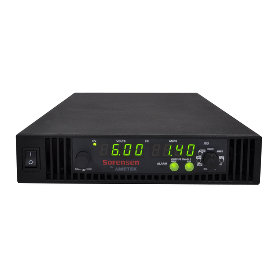
Introduction Front Panel Figure 1-1 XG/XTR Front Panels (Half Rack, above; Full Rack, below; not to-scale) Item Description Front panel power switch Front panel display. See Figure 1-2 for details. Air Intake Vents M370430-01 Rev B... -
Page 28: Front Panel Display And Controls
Introduction Front Panel Display and Controls Figure 1-2 Front Panel Display and Controls Item Description Rotary Adjust/Enter control Constant Voltage (CV) Mode LED (green) Model Identification Label Output Voltage Display Constant Current (CC) Mode LED (green) Output Current Display Alarm Indicator LED (red) OUTPUT ENABLE Main button OUTPUT ENABLE Aux button 9-Position Mode Control (For detailed information, see “Configuring Settings from the Front... -
Page 29: Rear Panel Connectors On 850 Watt Models
Introduction Rear Panel Connectors on 850 Watt Models Figure 1-3 XG/XTR 850 Watt Units: 6 V to 40 V Models Figure 1-4 XG/XTR 850 Watt Units: 60 V to 150 V Models Figure 1-5 XG/XTR 850 Watt Units: 300 V to 600 V Models M370430-01 Rev B... - Page 30 Introduction Item Description 6 V– 40 V Models: DC Output Terminal Positive 60 V–150 V Models: DC Output Connectors Positive (6.5 mm hole diameter) 300 V–600 V Models: DC Output Connectors Positive (6.5 mm hole diameter) 6 V– 40 V Models: DC Output Terminal Negative 60 V–150 V Models: DC Output Connectors Negative (6.5 mm hole diameter) 300 V–600 V Models: DC Output Connectors Negative (6.5 mm hole diameter) 3 (J2)
-
Page 31: Rear Panel Connectors On 1500 And 1700 Watt Models
Introduction Rear Panel Connectors on 1500 and 1700 Watt Models Figure 1-6 XG/XTR 1500 and 1700 Watt Units: 6 V to 40 V Models M370430-01 Rev B... -
Page 32: Figure 1-7 Xg/Xtr 1500 And 1700 Watt Units : 60 Vto 600 V Models
Introduction Figure 1-7 XG/XTR 1500 and 1700 Watt Units: 60 V to 600 V Models Item Description 6 V– 40 V Models: DC Output Terminal Positive (8.5 mm hole diameter) 60 V–600 V Models: DC Output Connectors Positive 6 V– 40 V Models: DC Output Terminal Negative (8.5 mm hole diameter) 60 V–600 V Models: DC Output Connectors Negative 3 (J2) Ethernet (ENET) or GPIB Connector (optional) -
Page 33: Installation
Installation Chapter 2, Installation, provides information and procedures for inspecting, installing, and testing the power supply. -
Page 34: Basic Setup Procedure
Installation Basic Setup Procedure Table 2-1 provides a summary of the basic setup procedure with references to the relevant sections in this chapter. Refer to this table if you are unfamiliar with the installation requirements for the power supply. Complete each step in the sequence given. Table 2-1 Basic Setup Procedure Step... -
Page 35: Step 1: Inspecting And Cleaning
Installation Step 1: Inspecting and Cleaning Initial Inspection When you first receive your unit, perform a physical check: Inspect the unit for any scratches and cracks, broken switches, connectors or displays. Ensure that the packing box contains the 7.5 foot (2.5 m) power cord (supplied with the XG/XTR 850 W model only). -
Page 36: Step 2: Location And Mounting
Installation Step 2: Location and Mounting The power supply may be rack-mounted or used in benchtop applications. Rack Mounting The XG/XTR 850 Watt power supply is designed to fill half of a standard 19 inch (483 mm) equipment rack. The XG/XTR 1500 and 1700 Watt power supplies are designed to fill a standard 19 inch (483 mm) equipment rack. -
Page 37: Step 3: Connecting Ac Input Power
Installation Step 3: Connecting AC Input Power WARNING: Shock hazard Disconnect AC power from the unit before removing the cover. Even with the front panel power switch in the Off position, live line voltages are exposed when the cover is removed. Repairs must be made by an Authorized Service Center. WARNING: Shock hazard There is a potential shock hazard if the power supply chassis and cover are not connected to an electrical ground via the safety ground in the AC input... -
Page 38: Xg/Xtr 1500 And 1700 Watt Ac Input Connector
Installation XG/XTR 1500 and 1700 Watt AC Input Connector On the XG/XTR family 1U, full 19-inch rack models, the AC input connector is a 3-terminal wire clamp located on the rear panel of the power supply. Figure 2-1 1500 and 1700 Watt AC Input Cover and Strain Relief XG/XTR 1500 and 1700 Watt AC Input Wire The full 19-inch rack models are not supplied with a power cord or a non-locking AC plug. -
Page 39: Xg/Xtr 1500 And 1700 Watt Ac Input Wire Connection
Installation XG/XTR 1500 and 1700 Watt AC Input Wire Connection To make the AC input wire connections: Strip the outside insulation on the AC cable approximately 4 in. (100 mm). Trim the wires so that the ground wire is 0.5 in. (12 mm) longer than the other wires. -
Page 40: Step 4: Selecting Load Wires
Installation Step 4: Selecting Load Wires This section provides recommendations for selecting minimum load wire sizes. Load Wiring To select the wiring for connecting the load to the power supply, consider the following factors: Insulation rating of the wire. Current carrying capacity of the wire. Maximum load wiring length for operation with remote sense lines. -
Page 41: Maximum Load Wiring Length For Operation With Sense Lines
Installation Maximum Load Wiring Length For Operation With Sense Lines WIRE GAUGE (AWG) LOAD CURRENT (AMPS) Figure 2-2 Maximum Load Wire Length for 1 V Line Drop Noise and Impedance Effects To minimize noise pickup or radiation, use shielded twisted pair wiring of the shortest possible length for load sense wires. -
Page 42: Step 5: Performing Functional Tests
Installation 5: Performing Functional Tests Step The functional test procedures include: Power-on and front panel functional checks Voltage mode operation and current mode operation checks. For information on local operation, see “Local Operation” on page 3-1 for adjusting front panel controls and settings. Powering the Power Supply On/Off To power on the power supply: Ensure that the front panel power switch is in the Off position. -
Page 43: Voltage And Current Mode Operation Checks
Installation Voltage and Current Mode Operation Checks To perform the voltage and current mode operation checks: Ensure that the front panel power switch is in the On position and the output is disconnected. If the OUTPUT ENABLE Main button is illuminated, press the button to turn off the output. -
Page 44: Step 6: Connecting Loads
Installation Step 6: Connecting Loads This section describes how to connect loads to the power supply for both single and multiple loads. WARNING: Shock hazard There is a shock hazard at the power supply output when operating at an output greater than 40 V. -
Page 45: Inductive Loads And Batteries
Installation Inductive Loads and Batteries CAUTION The XG/XTR power supply requires freewheeling and blocking diodes across the output while driving inductive loads or batteries to protect the power supply from damage caused by power being fed back into the supply and from high voltage transients. Selecting The diode must have a voltage rating at least 20% greater than the power Diodes... -
Page 46: Connecting Single Loads
Installation Connecting Single Loads Figure 2-3 shows the recommended load connections for a single load which is sensing its voltage locally. Local sense lines shown are the default connections at the rear panel APG J1 connector (see Figure 4-1 on page 4-5). The load lines should use the largest gauge and shortest length of wire possible to ensure optimal performance. -
Page 47: Step 7: Connecting Remote Sensing
Installation Step 7: Connecting Remote Sensing WARNING: Shock hazard There is a potential shock hazard at the sense connectors when using a power supply at an output greater than 40 V. Select wiring with a minimum insulation rating equivalent to the maximum output voltage of the power supply for use as local sense jumpers or for remote sense wires. - Page 48 Installation Connect one end of the shield of the twisted pair wire to the chassis ground point on the power supply. Connect the positive sense line (+SNS) from the positive regulation point as close as possible to the load terminals to pin J1.
-
Page 49: Local Operation
Local Operation Chapter 3, Local Operation, provides the procedures for local (front panel) operation such as: Configuring settings. Operating in constant voltage mode, constant current mode, and constant power mode (available in version 2.21 and higher). Using the protection features. Using multiple power supplies. -
Page 50: Introduction
Local Operation Introduction Once you have installed the power supply and connected both the AC input power and the load (covered in “Installation” on page 2-1), the power supply is ready for local operation. To turn the power supply on, see “Powering the Power Supply On/Off”... -
Page 51: Coarse And Fine Adjustment Modes
Local Operation Coarse and Fine Adjustment Modes The coarse and fine adjustment modes are used for setting the voltage and current set points, OVP and UVP settings. When using local operation to set the current and voltage set points, use Coarse adjustment the coarse adjustment mode (default) followed by the fine adjustment mode... - Page 52 Local Operation Select and Set from the Front Panel cont’d) Table 3-1 9 Positions on the Mode Turning the rotary Adjust/Enter Pressing the rotary Adjust/ Control Knob control lets you... Enter control lets you... CAP (Current Analog Select the programming source and Set the value selected and cycle Programming) select the range.
-
Page 53: Navigating The Menu System
Local Operation Navigating the Menu System The menu system of the XG/XTR follows a select and set model with the exception of the VOLTS and AMPS modes. See “Setting VOLTS and AMPS Modes”. The general procedure for setting up the features in the select and set model is: To select a mode, rotate the 9-position Mode control to the desired mode or press the rotary Adjust/Enter control once to... - Page 54 Local Operation To access the tracking mode for entering voltage and current: Select the VOLTS or AMPS position on the 9-position mode control. If the set point is blinking, the unit is in coarse tracking mode. When the VOLTS mode is selected, the voltage set point will blink in the output voltage display.
-
Page 55: Normal Display Mode And Inactivity Timeout
Local Operation Normal Display Mode and Inactivity Timeout Normal display mode appears on the output voltage and current displays when the configuration changes from the front panel have been completed or when the inactivity timeout occurs (default is 3 seconds). Normal display mode shows the output voltage and current values. -
Page 56: Figure 3-2 Front Panel Menu System
Local Operation Coarse Volt Pre-Set Fine Volt Pre-Set Coarse Volt Tracking Fine Volt Tracking VOLTS Coarse Curert Pre-Set Fine Current Pre-Set AMPS Coarse Current Tracking Fine Current Tracing Fold Delay Fold Delay None OVP Coarse Adjust OVP Flne Adjust UVP Coarse Adjust UVP Fine Adjust OPP ON/OFF SD I/O... -
Page 57: Display Messages On The Front Panel
Local Operation Display Messages on the Front Panel The front panel displays on the power supply will use text as shown in Table 3-2 to indicate the status or mode. Table 3-2 Front Panel Display Text Display Text Text Description Negative Polarity RS 232 RS 485... - Page 58 Local Operation Display Text Text Description Interlock ENET Interface Current APG Level Voltage APG Level Lock Local Loop Protection Output Protection Over Current Protection Over Temperature Protection Over Voltage Protection Over Voltage Protection fine adjustment OVP Calibration Polarity Protection mode Power Supply Unit Isolated Resistive Analog Programming Recall Preset...
- Page 59 Local Operation A blinking numeric value is either a voltage or current set point in tracking mode. The display in which the set point appears, output voltage or output current display, indicates the type of set point, voltage or current. M370430-01 Rev B 3-11...
-
Page 60: Standard (Local) Operation
Local Operation Standard (Local) Operation The power supply can be controlled by two methods, either from the front panel or from any of the remote interfaces. Front panel control is referred to as local operation (default setting) while control via any of the remote interfaces is called remote operation. - Page 61 Local Operation The mode of operation is not determined until the output is enabled. The Output disabled CV and CC mode LEDs will not indicate the mode while the output is disabled. Constant Voltage (CV) Mode Operation If the output is enabled and the configured current set point is much higher than the requirements for the attached load, then the voltage will rise until it reaches the voltage set point.
- Page 62 Local Operation Automatic Mode Crossover Mode crossover occurs when the unit makes the switch between operating modes. Crossover can occur from CV to CC or vice versa, depending on how the attached load resistance changes. Figure 3-3 shows the relationships between the variables. For example, if the unit was initially operating in CV mode with the output voltage at the voltage set point and the load current below the and the attached load resistance began to decrease, the current...
-
Page 63: Figure 3-3 Operating Modes
Local Operation The reverse operating mode change can also occur if the load resistance is increased to the point that the required load current drops below the value. At that point the power supply would crossover to CV mode and the load current would be free to vary as the load resistance changed. - Page 64 Local Operation Once the desired value has been set, press the rotary Adjust/Enter control to commit the setting. Important: The control circuits have been designed to allow you to set the output voltage up to 105% over the model-rated maximum value. The power supply will operate within these extended ranges, but full performance to specification is not guaranteed.
-
Page 65: Shipped Configuration (Local Operation)
Local Operation Shipped Configuration (Local Operation) The power supply is configured for local operation at the factory. See Table 3-3 for a summary of this configuration. For more information on default settings, see Table 3-9 on page 3-43. Table 3-3 Shipped Configuration Local Control Configuration Additional References... -
Page 66: Enabling The Auxiliary Output
Local Operation Enabling the Auxiliary Output To enable on the auxiliary output: Press the OUTPUT ENABLE Aux button on the front panel. The OUTPUT ENABLE Aux button will illuminate. Important: The auxiliary output will not be enabled if the external AUX_ON_OFF signal line is being used to disable the auxiliary outputs. -
Page 67: Auxiliary Auto Start Mode
Local Operation Auxiliary Auto Start Mode The Auxiliary Auto Start mode determines the state of the auxiliary output after a complete power cycle (all front panel LEDS are not illuminated). With Auxiliary Auto Start mode turned to On, the auxiliary output will be activated after the power supply is powered up again. - Page 68 Local Operation Press the rotary Adjust/Enter control to commit the Constant Power operation. To disable Constant Power operation: Turn the 9-position mode control to the FLD position or press the rotary Adjust/Enter control if the 9-position mode control is already at the FLD position. “”...
-
Page 69: Alarms And Errors
Local Operation Alarms and Errors Several conditions can cause alarms in the XG/XTR. Some conditions are: From user configurable features. Controlled in hardware and will trigger regardless of configuration. All alarms, with the exception of the Fan alarm, will result in the output of the power supply being disabled. -
Page 70: Clearing Alarms
Local Operation Clearing Alarms Clearing Triggered and Manual Alarms To clear a triggered alarm, use one of the following methods: Turn the power supply Off and then On. Press and hold the rotary Adjust/Enter control for 3 seconds. To clear a manual alarm: Press and hold the rotary Adjust/Enter control for 3 seconds. -
Page 71: Front Panel Alarm Led
Local Operation Clearing Automatic Alarms Some alarms will clear automatically when the condition that caused the alarm is no longer present. When an alarm automatically clears, the output voltage and current displays will return to normal, but the ALARM LED will remain illuminated to indicate that an alarm has occurred. -
Page 72: Alarm Masking
Local Operation The alarm LED will remain illuminated until the alarm is manually cleared (see “Clearing Triggered and Manual Alarms” on page 3-22) or by turning the main output on if the alarm has automatically been cleared. Alarm Masking It is possible to completely disable some alarms through the use of the alarm mask. -
Page 73: Alarm Output Latching
Local Operation Alarm Output Latching When an alarm is triggered, the output will be disabled with the exception of the Fan alarm. When an alarm is cleared, the alarm output latch determines if the output should be re-enabled to the state before the alarm occurred or if the output should remain in the off state. -
Page 74: Setting Foldback Mode
Local Operation Setting Foldback Mode Foldback mode is used to disable the output when a transition is made between the operating modes. The power supply will turn off/disable the output and lock in foldback mode after a specified delay if the power supply transitions into CV mode or into CC mode, depending on the foldback mode settings. -
Page 75: Resetting Activated Foldback Protection
Local Operation Press the rotary Adjust/Enter control to commit the setting once the desired value has been set. The green FLD LED will turn off and the display will return to the normal display mode. The SCPI command (s) for these instructions are: [:]OUTPut[<channel>]:PROTection:FOLDback[:MODE] [:]OUTPut[<channel>]:PROTection:FOLDback:LATCh Important: If you set foldback while the output is enabled and the trigger you... -
Page 76: Using Over Voltage Protection (Ovp)
Local Operation Using Over Voltage Protection (OVP) The OVP circuit protects the load in the event of an analog programming error, an incorrect voltage control adjustment, or a power supply failure. The OVP circuit monitors the output voltage at the output of the power supply and will disable the output whenever a preset voltage set point is exceeded. -
Page 77: Defining The Ovp Set Point
Local Operation Defining the OVP Set Point To define the OVP set point: Turn the power supply On. Ensure the voltage is lower than the desired set point. Set the output to the desired voltage. OVP can be set without setting desired output voltage first. Turn the 9-position mode control to the PRT position. -
Page 78: Using Under Voltage Protection (Uvp)
Local Operation Using Under Voltage Protection (UVP) Important: UVP will not be active for voltage set points that are less than 1% of model voltage. The UVP prevents voltage settings below a set value. The UVP lets you create a voltage window of operation when used in conjunction with the OVP setting. -
Page 79: Defining The Uvp Set Point
Local Operation Defining the UVP Set Point To define the UVP set point: Turn the power supply On. Set the output to the desired voltage. Turn the 9-position mode control to the PRT position. is displayed. Turn the rotary Adjust/Enter control until displayed. -
Page 80: Using Over Temperature Protection Lock (Otp)
Local Operation Using Over Temperature Protection Lock (OTP) The OTP lock protects the power supply in the event of an over temperature alarm. This alarm could be caused by ventilation restriction or overheating due to fan failure. Two modes are available: Auto recovery (OTP OFF) where the power supply turns on again after cooling down. -
Page 81: Using The External Shutdown Function
Local Operation Using the External Shutdown Function Use the external shutdown function to enable or disable the output of the power supply via a logic level signal. When the external shutdown is triggered, the power supply will display SD POL on the output voltage and current displays. -
Page 82: Defining The Polarity Of The External Shutdown Signal
Local Operation Defining the Polarity of the External Shutdown Signal Turn the 9-position mode control to the PRT position or press the rotary Adjust/Enter control if the control knob is already at the PRT position. is displayed on the output voltage display. Turn the rotary Adjust/Enter control until displayed. -
Page 83: Setting Up Loop Protection
Local Operation Setting up Loop Protection To set up Loop Protection: With the AC powered OFF, connect the first unit’s pin J13.13 to the next unit’s J 13.12 on the AUX Output and Isolated Analog Programming Connector. Do this for up to four units. An example of a 3-unit loop protection is illustrated as follows: To enable or disable Loop Protection: Turn the 9-position mode control to the PRT position. -
Page 84: Interlock Function
Local Operation Interlock Function The Interlock function can be used to wire an external shutoff switch that can be used to enable or disable the power supply output. When the switch is closed, the power supply will operate normally. If the switch is opened, the power supply will trigger the interlock alarm. -
Page 85: Programming Current Output Preset
Local Operation Turn to display Press to commit the selected setting. Important: This single front panel operation affects both power on and output enable. However, when using SCPI, there is a separate command for each. The SCPI command to query or enable/disable the 0 Voltage Output Preset at power-on is: [:]SYSTem[<channel>]:PON:VOLTage {?|ON|OFF}... -
Page 86: Power On Status Signal
Local Operation Power On Status Signal Power On Status signal indicates a fault condition in the power supply. Power On Status signal is a TTL output signal at Pin J2.13 with reference to COM ISOLATED (Pin J2.2 or Pin J2.6). During normal operation, the Power On Status signal will be high. -
Page 87: Current Configuration Memory Settings
Local Operation Current Configuration Memory Settings The power supply will save the unit settings at the time of power down. These settings will be loaded when the power is restored to the unit or the power supply is powered up again. Table 3-7 lists the settings that are saved and recalled on a power cycle event. -
Page 88: User Setting Memory Locations
Local Operation User Setting Memory Locations There are three user setting memory locations available for storing frequently used configurations. These user setting memory locations help to facilitate multiple users of an XG/XTR power supply who have different setups or when multiple loads are used that have different requirements. -
Page 89: Recalling User Setting Memory Locations
Local Operation The SCPI command (s) for these instructions are: *SAV <setting_location> [:]SYSTem[<channel>]:SAVE <setting_location> Recalling User Setting Memory Locations This feature recalls settings that were previously saved. To load user setting memory locations: Turn the 9-position mode control to the RCL position. is displayed on the output voltage display with a number indicating a preset position on the output current display. -
Page 90: Local Lockout
Local Operation Local Lockout Local lockout is a feature that allows the front panel to be locked so that accidental button presses are ignored. This feature is often used to lockout the front panel when you are controlling the power supply from a remote location. -
Page 91: Resetting The Power Supply
Local Operation Resetting the Power Supply The reset is used to clear the parameters to the factory default values. Soft Reset The soft reset is used to set the parameters (see Table 3-9) to the default values, but it does not reset the calibration constants To perform a soft reset: Turn the power supply to Off then On. - Page 92 Local Operation Table 3-9 Power Supply Default Settings Parameter Setting Foldback trigger None Foldback delay 0.5 s Current Share Mode Controller Alarm Output Latches 263 (0 x 107, all latches enabled) Alarms Mask 2047 (0 x 7FF, all enabled) Interlock Disabled Voltage Analog Programming Voltage APG Scale...
-
Page 93: Using Multiple Power Supplies
Local Operation Using Multiple Power Supplies WARNING: Shock hazard There is a shock hazard at the load when using a power supply at an output of greater than 40V or a combined output of greater than 40V. To protect personnel against accidental contact with hazardous voltages created by a series connection, ensure that the load, including connections, has no live parts which are accessible. -
Page 94: Figure 3-4 Split Supply Operation
Local Operation Power Supply Common Load Power Supply Figure 3-4 Split Supply Operation 3-46 M370430-01 Rev B... -
Page 95: Configuring Multiple Supplies For Series Operation
Local Operation Configuring Multiple Supplies for Series Operation A maximum of two power supplies of the same rating can be connected in series to increase the output voltage. CAUTION: Equipment damage When two power supplies are connected in series, they should be programmed to the same output voltage to prevent damage to the lower voltage supply at short circuit condition. -
Page 96: Figure 3-5 Series Operation
Local Operation Figure 3-5 Series Operation 3-48 M370430-01 Rev B... -
Page 97: Figure 3-6 Load Connections In Remote Sensing Mode
Local Operation Connecting to the Load in Remote Sensing Mode Connect the negative (-) output terminal of one power supply to the positive (+) output terminal of the next power supply. The more positive supply's positive sense line should connect to the positive terminal of the load (or distribution point). -
Page 98: Configuring Multiple Supplies For Current Sharing Operation (Apg Method)
Local Operation Configuring Multiple Supplies for Current Sharing Operation (APG Method) Up to four power supplies can be connected in parallel to increase the output current. One of the units will operate as the master unit and the remaining units will operate as slave units controlled by the master unit. The master unit uses the analog programming lines to set the output voltages and currents of the slave units to match its output. - Page 99 Local Operation Press the rotary Adjust/Enter control to commit the setting. The SCPI command (s) for these instructions are: [[:]SOURce[<channel>]]:COMBine:CSHare[:MODE] Setting up the Slave Units The output voltage and current of the slave units should be programmed to maximum value. During parallel operation, the slave units operate as a controlled current source following the controller unit's output current.
-
Page 100: Connecting To The Load In Local Sensing Mode (Parallel Control Method)
Local Operation Setting Foldback Protection Foldback protection is only available on the master units as the slaves operate in constant current mode. They should never crossover into constant voltage mode. If foldback is triggered on the master unit, when its output shuts down, it will program the slave unit's output to zero volts. -
Page 101: Connecting To The Load In Remote Sensing Mode (Parallel Control Method)
Local Operation Connecting to the Load in Remote Sensing Mode (Parallel Control Method) MASTER PSU Shielded Twisted Pair LOAD To other slaves SLAVE PSU Figure 3-8 Load Connections in Remote Sensing Mode (Parallel Control Method) M370430-01 Rev B 3-53... - Page 102 Local Operation 3-54 M370430-01 Rev B...
-
Page 103: Analog Programming (Apg) And Isolated Analog Programming (Isol)
Analog Programming (APG) and Isolated Analog Programming (ISOL) Chapter 4, Analog Programming (APG) and Isolated Analog Programming (ISOL), provides information and procedures for analog and isolated analog programming of the power supply. -
Page 104: Introduction
Analog Programming (APG) and Isolated Analog Programming (ISOL) Introduction The rear panel connectors J1 and J3 provide an option to control and monitor the output of the power supply with analog signals. Connector J1 provides a non-isolated analog interface where all signals are referenced to the negative output terminal of the power supply. -
Page 105: Remote Programming Options
Analog Programming (APG) and Isolated Analog Programming (ISOL) Remote Programming Options Analog Monitor Signals There are four monitor lines for analog programming the pin name and the related APG mode, which are listed in Table 4-1. All of these lines are provided to give analog feedback. -
Page 106: Table 4-2 Remotep
Analog Programming (APG) and Isolated Analog Programming (ISOL) Auxiliary Outputs The auxiliary outputs are an additional isolated source. The auxiliary output has two outputs: +5 V output on J3.9 and a +15 V output on J3.11. The auxiliary output operates independently of the main output. -
Page 107: Analog Programming (Apg) Connector J1
Analog Programming (APG) and Isolated Analog Programming (ISOL) Analog Programming (APG) Connector J1 The APG connector is an 18-pin connector. See Figure 4-1. The APG connector provides access to the following functions: Sense control Analog programming and monitoring. Jumper Jumper Figure 4-1 APG Connector Terminals Table 4-3 APG Pins and Functions J1... - Page 108 Analog Programming (APG) and Isolated Analog Programming (ISOL) Table 4-3 APG Pins and Functions J1 Reference Function J1.9 VOL_PR Analog Voltage Programming Input J1.10 CUR_PR Analog Current Programming Input J1.11 VOL_RES_PR Voltage Resistive Programming Input J1.12 CUR_RES_PR Current Resistive Programming Input J1.13 VOL_MON Voltage Monitor.
-
Page 109: S Pring T Erminal B Lock
Analog Programming (APG) and Isolated Analog Programming (ISOL) Making Control Connections CAUTION: Equipment damage Before making connections from external circuits to the Analog Programming Connector, turn the front panel power switch to Off and wait until the front panel displays are not illuminated. CAUTION: Equipment damage Program/monitor signal and return are internally connected to the power supply negative output (-S). - Page 110 Analog Programming (APG) and Isolated Analog Programming (ISOL) Wiring WARNING: Shock hazard There is a potential shock hazard at the output when using a power supply with a rated output greater than 60 V. Use load wiring with a minimum insulation rating equivalent to the maximum output voltage of the power supply.
-
Page 111: Analog Programming Mode
Analog Programming (APG) and Isolated Analog Programming (ISOL) Analog Programming Mode For more details about connections for your particular model, see “Rear Panel Connectors on 850 Watt Models” on page 1-7 or “Rear Panel Connectors on 1500 and 1700 Watt Models” on page 1-9. -
Page 112: Voltage-Controlled Voltage Apg Setup
Analog Programming (APG) and Isolated Analog Programming (ISOL) Voltage-Controlled Voltage APG Setup Activating APG Voltage Mode To activate APG voltage mode using an external voltage source: Turn the 9-position mode control to the VAP position or press the rotary Adjust/Enter control if the mode control is already at the VAP position. - Page 113 Analog Programming (APG) and Isolated Analog Programming (ISOL) Query for Analog Voltage Input Level To query for analog voltage input level from non-isolated input: Turn the 9-position mode control to the VAP position or press the rotary Adjust/Enter control if the mode control is already at the VAP position.
-
Page 114: Voltage-Controlled Current Apg Setup
Analog Programming (APG) and Isolated Analog Programming (ISOL) Voltage-Controlled Current APG Setup Activating APG Current Mode To activate APG current mode using an external voltage source: Turn the 9-position mode control to the CAP position or press the rotary Adjust/Enter control if the mode control is already at the CAP position. - Page 115 Analog Programming (APG) and Isolated Analog Programming (ISOL) Query for Analog Current Input Level To query for analog current input level from non-isolated input: Turn the 9-position mode control to the CAP position or press the rotary Adjust/Enter control if the mode control is already at the CAP position.
-
Page 116: O Utput V Oltage Using An E Xternal R Esistor
Analog Programming (APG) and Isolated Analog Programming (ISOL) Analog Programming With External Resistor The pin numbers are described in Table 4-3 on page 4-6. Figure 4-6 Programming Output Voltage using an External Resistor APG Connector Figure 4-7 Programming Output Current using an External Resistor 4-14 M370430-01 Rev B... -
Page 117: Resistive-Controlled Voltage Apg Setup
Analog Programming (APG) and Isolated Analog Programming (ISOL) Resistive-Controlled Voltage APG Setup To activate APG voltage mode using an external resistor: Turn the 9-position mode control to the VAP position or press the rotary Adjust/Enter control if the mode control is already at the VAP position. - Page 118 Analog Programming (APG) and Isolated Analog Programming (ISOL) Query for Analog Voltage Input Level To query for analog voltage input level from non-isolated input: Turn the 9-position mode control to the VAP position or press the rotary Adjust/Enter control if the mode control is already at the VAP position.
-
Page 119: Resistive-Controlled Current Apg Setup
Analog Programming (APG) and Isolated Analog Programming (ISOL) Resistive-Controlled Current APG Setup To activate APG current mode using an external resistor source: Turn the 9-position mode control to the CAP position to press the rotary Adjust/Enter control if the control knob is already at CAP position. - Page 120 Analog Programming (APG) and Isolated Analog Programming (ISOL) Query for Analog Current Input Level To query for analog current input level from non-isolated input: Turn the 9-position mode control to the CAP position or press the rotary Adjust/Enter control if the mode control is already at the CAP position.
-
Page 121: Voltage And Current Readback
Analog Programming (APG) and Isolated Analog Programming (ISOL) Voltage and Current Readback The pin numbers are described in Table 4-3 on page 4-6. Figure 4-8 Voltage Readback Using APG Connector J1 Figure 4-9 Current Readback Using APG Connector J1 M370430-01 Rev B 4-19... -
Page 122: Isolated Analog Programming Mode (Isol)
Analog Programming (APG) and Isolated Analog Programming (ISOL) Isolated Analog Programming Mode (ISOL) See “Rear Panel Connectors on 850 Watt Models” on page 1-7 “Rear Panel Connectors on 1500 and 1700 Watt Models” on page 1-9 for more details about connections. AUX Output and Isolated Analog Programming (ISOL) Connector The AUX Output and Isolated Analog Programming (ISOL) Connector is a 15-pin female DSUB connector. -
Page 123: Table 4-4 Aux Output And Table 5-1 Remote Control
Analog Programming (APG) and Isolated Analog Programming (ISOL) Table 4-4 AUX Output and ISOL Connector Pins and Functions J3 Reference Function J3.1 AUX_ON_OFF Auxiliary enable/disable J3.2 COM_ISOLATED Isolated Common (Isolated from Main Output and Communication. Return wire for +5 V, +15 V Auxiliary Voltage. J3.3 IS_VOL_PR_VOL Isolated Analog Voltage Programming Input... - Page 124 Analog Programming (APG) and Isolated Analog Programming (ISOL) Making ISOL Control Connections CAUTION: Equipment damage Before making connections from external circuits to the Isolated Analog Programming Connector, turn the front panel power switch to off and wait until the front panel displays have gone out. For most connectors and jumpers, use any suitable wire such as 22 AWG stranded wire.
-
Page 125: Voltage-Controlled Voltage Isol Setup
Analog Programming (APG) and Isolated Analog Programming (ISOL) Voltage-Controlled Voltage ISOL Setup Activating ISOL Programming Voltage Mode To activate ISOL programming voltage mode with an external voltage source: Turn the 9-position mode control to the VAP position or press the rotary Adjust/Enter control if the mode control is already at the VAP position. - Page 126 Analog Programming (APG) and Isolated Analog Programming (ISOL) Query for ISOL Voltage Input Level To query for ISOL voltage input level from non-isolated input: Turn the 9-position mode control to the VAP position or press the rotary Adjust/Enter control if the control knob is already at the VAP position.
-
Page 127: Voltage-Controlled Current Isol Setup
Analog Programming (APG) and Isolated Analog Programming (ISOL) Voltage-Controlled Current ISOL Setup Activating ISOL Programming Current Mode Turn the 9-position mode control to the CAP position or press the rotary adjust/Enter control if the control knob is already at the CAP position. is displayed on the output voltage display. - Page 128 Analog Programming (APG) and Isolated Analog Programming (ISOL) Query for ISOL Current Input Level To query for ISOL current input level from non-isolated input: Turn the 9-position mode control to the CAP position or press the rotary Adjust/Enter control if the control knob is already at the CAP position.
- Page 129 Analog Programming (APG) and Isolated Analog Programming (ISOL) Analog Programming With External Resistor The pin numbers are described in Table 4-4 on page 4-21. ISOL Connector Figure 4-13 Programming Output Voltage using an Isolated External Resistor ISOL Connector Figure 4-14 Programming Output Current using an Isolated External Resistor M370430-01 Rev B 4-27...
-
Page 130: Resistive-Controlled Voltage Isol Setup
Analog Programming (APG) and Isolated Analog Programming (ISOL) Resistive-Controlled Voltage ISOL Setup Activating ISOL Programming Voltage Mode To activate ISOL programming voltage mode using an external resistor: Turn the 9-position mode control to the VAP position or press the rotary adjust/Enter control if the control knob is already at the VAP position. - Page 131 Analog Programming (APG) and Isolated Analog Programming (ISOL) Query for ISOL Voltage Input Level To query for ISOL voltage input level from non-isolated input: Turn the 9-position mode control to the VAP position or press the rotary Adjust/Enter control if the control knob is already at the VAP position.
-
Page 132: Resistive-Controlled Current Isol Setup
Analog Programming (APG) and Isolated Analog Programming (ISOL) Resistive-Controlled Current ISOL Setup Activating ISOL Resistive-Controlled Current Setup Turn the 9-position mode control to the CAP position or press the rotary Adjust/Enter control if the control knob is already at the CAP position. is displayed on the output voltage display. - Page 133 Analog Programming (APG) and Isolated Analog Programming (ISOL) Query for ISOL Current Input Level To query for ISOL current input level from non-isolated input: Turn the 9-position mode control to the CAP position or press the rotary Adjust/Enter control if the control knob is already at the CAP position.
-
Page 134: Voltage And Current Readback (Isolated)
Analog Programming (APG) and Isolated Analog Programming (ISOL) Voltage and Current Readback (Isolated) The pin numbers are described in Table 4-4 on page 4-21. ISOL Connector Figure 4-15 Isolated Voltage Monitoring ISOL Connector Figure 4-16 Isolated Current Monitoring Query Remote Control Source State Quick Tip Remote The SCPI command for these instructions are: operation uses these... -
Page 135: Remote Operation
Remote Operation Chapter 5, Remote Operation, describes the remote operation of the XG/XTR power supply via the communication ports. -
Page 136: Introduction
Remote Operation Introduction In addition to the front panel interface, the XG/XTR can be remotely controlled through the various remote interfaces. The XG/XTR implements the SCPI standard as its command line interface for remotely controlling the power supply. Additionally, a small subset of legacy commands has been provided for ease of use and backwards compatibility. -
Page 137: C Ontrol C Onnectors
Remote Operation RS-232 and RS-485 connector in port RS-232 and RS-485 connector out port Figure 5-1 Remote Control Connectors Table 5-1 Remote Control Connector Pins and Functions J4 and J6 Reference Direction Function J4.1 RX-232 Input RS-232 J4.2 TX-232 Output RS-232 J4.3 RXD+... -
Page 138: Table 5-2 Db-9 Pinouts
Remote Operation RS-232 Communication Cable with RJ-45 to DB-9 Communication control cable with DB-9 connector (male) on the PC side and RJ-45 shielded connector on the power supply. The cable length should be 9.84 feet (3 m) or longer. Table 5-2 DB-9 Pinouts Name Description... -
Page 139: C Able With Db-9 P Inout
Remote Operation DB-9 Pinout DB-9 connector on PC RJ-45 plug Figure 5-2 RS-232 Communication Cable with DB-9 Pinout RS-232 Communication Cable with RJ-45 to DB-25 Communication control cable with DB-25 pinout (male) on the PC side and RJ-45 shielded connector on the power supply. The cable length should be 9.84 feet (3 m) or longer. -
Page 140: C Able With Db-25 P Inout
Remote Operation Figure 5-4 RS-232 Communication Cable with DB-25 Pinout Completing the Setup To complete the setup: Configure the XG/XTR to use the 232 remote interface and set up the terminal that will be used on the connected PC. See the sections entitled”Selecting the Appropriate Communication Port”... -
Page 141: Configuring Remote Control Using Rs-485
Remote Operation Configuring Remote Control Using RS-485 RS-485 Communication Cable with RJ-45 to DB-9 Communication control cable with DB-9 pinout (female) on the PC side (see Figure 5-2) and RJ-45 shielded connector on the power supply. Table 5-5 DB-9 Pinouts Name Description Ground... -
Page 142: Unit
Remote Operation RS-485 Communication Cable with Two RJ-45s Use the top connector of the two 8-pin RJ-45 jacks, as shown in Figure 5-1, to connect to the RS-485 remote interface. Communication cable with two RJ-45 shielded connectors (see Figure 5-3) connecting the master unit to the slave unit. -
Page 143: Configuring Remote Control Using The Usb Connector
Remote Operation Configuring Remote Control using the USB Connector The power supply can be controlled from a remote terminal using a USB interface. The standard USB connector is located on the rear panel of both the XG/XTR 850 Watt model, as shown in Figure 1-3 on page 1-7 and the XG/XTR 1500 and 1700 Watt models, as shown in Figure 1-6 on page 1-9. -
Page 144: Wizard
Remote Operation Figure 5-7 Found New Hardware Wizard Click Next. On the Install Hardware Device Driver screen, select “Search for a suitable driver for my device (recommended)” and click Next. See Figure 5-8. Figure 5-8 Install Hardware Device Drivers 5-10 M370430-01 Rev B... -
Page 145: New Hardware Wizard,
Remote Operation In the Locate Driver Files dialog box, in the field Optional Search Locations, select Specify A Location and click Next. 10. On the next screen, enter the file path “C:\FTDI” and click 11. On the next screen, select “Driver Files Search Results” and click Next. -
Page 146: M Anager
Remote Operation To verify that the device has been installed: In Control Panel, go to System, click the Hardware tab and click on Device Manager. On the View menu, select Devices by Type. To change the virtual COM port properties, select the USB Serial Port and then Click Properties. -
Page 147: P Ort (Com1) P Roperties
Remote Operation Figure 5-11 Communications Port (COM1) Properties In the COM port list, scroll to the required COM port. Figure 5-12 Completing the new hardware wizard Click OK. Ensure that you do not select a COM port which is already in use. This selection is particularly useful for programs, such as HyperTerminal, which only work with COM1 through to COM4. - Page 148 Remote Operation Complete the Setup To complete the setup: Configure the XG/XTR to use the USB remote interface and set up the terminal that will be used on the connected PC. See “Selecting the Appropriate Communication Port” on page 5-24 and “Terminal Configuration”...
-
Page 149: Gpib Connector (Optional)
Remote Operation GPIB Connector (Optional) The power supply can be programmed from a remote terminal using a General Purpose Interface Bus (GPIB interface The GPIB interface is an 8-bit parallel data bus having a host of bus commands for synchronization and up to one megabyte data transfer rate. - Page 150 Remote Operation Communication with Your Device This section provides information on selecting the GPIB interface as the communication port used on the XTR, and it also provides an example of how commands can be sent and received. The details of the IEEE 488.2 and SCPI status reporting register structures and a complete list of commands available can be found later in this section.
-
Page 151: I Nstruments
Remote Operation Figure 5-13 Scanning for Instruments In the right window, click on Instrument 0 and review the device properties. See Figure 5-14. M370430-01 Rev B 5-17... -
Page 152: P Roperties
Remote Operation Figure 5-14 Instrument Properties Click Communicate with Instrument in the GPIB Explorer toolbar. See Figure 1-3. NI-488.2 Communicator appears. In the Send String box of the NI-488.2 Communicator window, type *IDN? and click the Query button. Important: If you press Enter while typing the string to be sent, the NI-488.2 Communicator program will exit. -
Page 153: Ethernet/Lan (Enet) Connector (Optional)
Remote Operation Ethernet/LAN (ENET) Connector (Optional) The power supply also can be programmed from a remote terminal using the Ethernet (ENET). If your power supply is configured with the Ethernet option, set-up instructions differ between the 850 Watt models and the 1500 and 1700 Watt models. For the XG/XTR 850 Watt power supply with the MEA option, see SETTING UP XG/XTR 850 WATT MODELS in Section 6 “Communications Options”... - Page 154 Remote Operation Multiple Power Supply Setup Master Setup: Configure the master XG/XTR by selecting the communication interface you wish to use to communication with the Master and follow the setup instruction in this chapter. Important: If either RS-232 or RS-485 are used for communication with the master, the data rate must be configured for 9600 bps to properly communicate with the slave units.
-
Page 155: Terminal Configuration
Remote Operation Terminal Configuration The terminal program allows serial communication with the power supply. To use a terminal program, set it up using the parameters from the following sections. If you wish to use HyperTerminal, see “HyperTerminal” on page 5-21 for instructions setting it up. Data Format Serial data format is 8 bit, one stop bit. - Page 156 Remote Operation This is the COM port that you have your serial cable hooked up to or in the case of USB the one that was configured to be used in the FDTI software. Click OK when done. Setup the data format to be used. See “Data Format” on page 5-21 for details.
-
Page 157: Etup
Remote Operation Figure 5-17 ASCII Setup 11. Check the following boxes: Send line ends with line feeds. Echo typed characters locally. Append line feeds to incoming line ends. Wrap lines that exceed terminal width. 12. Change the Line delay to 30 milliseconds. 13. -
Page 158: Selecting The Appropriate Communication Port
Remote Operation Selecting the Appropriate Communication Port Five ports are available for remote digital programming and readback: RS-232 RS-485 GPIB (optional) ENET (optional) To select a communication port: Turn the 9-position mode control to PGM. is displayed in the output voltage display. Turn the rotary Adjust/Enter control to select one of the communication ports: 232, 485, gPI b, USb, LAn. -
Page 159: Multichannel Address Setting
Remote Operation Multichannel Address Setting The power supply multichannel address can be set to any address between 1 to 30. All units that are connected together via the RS-232 or RS-485 connector must have a unique multichannel address. To set the address: Select the appropriate communication port as described “Selecting the Appropriate Communication Port”... -
Page 160: Remote Interface Addressing
Remote Operation Remote Interface Addressing All commands must be issued with a multichannel address or the device must be selected using the: *adr or :SYST[<channel>]:COMM[:MCH]:ADDR commands. Once a device is selected all commands sent without a multichannel address will be handled by the selected device. The use of multichannel addresses supersedes the selected device as the destination for a message. -
Page 161: Multichannel Commands Explained
Remote Operation Multichannel Commands Explained The use of multichannel addressing allows you to send messages to one device, more than one device or to all devices. Any of the remote interface types can be used to send a multichannel command through the device that is physically connected to the PC to all the devices, provided that all other devices are connected to via the RS-485 bus. - Page 162 Remote Operation Multichannel commands are particularly useful for configuring groups of devices that require identical configurations. The SCPI Commands for these instructions are: [:]<root command> <ALL|addr1>[,[ ]<addr2>][,[ ]<addr3>][,...]:<command> <parameter> For example: sour 1, 2, 3, 7:volt 4.5 syst4,5,6:oper:enab 255 syst ALL:clear output0:stat on 5-28 M370430-01 Rev B...
-
Page 163: Status Reporting In Scpi
Remote Operation Status Reporting in SCPI The status reporting implemented in the XG/XTR is primarily dictated by the SCPI standard. This section provides a high level review of the standard status reporting required by SCPI and then covers the XG/XTR specific reporting that is implemented within the SCPI status reporting framework. -
Page 164: R Eporting M Odel
Remote Operation QUEStionable Status VOLTage CURRent Error/Event Queue TIME POWer TEMPerature FREQuency PHASe MODulation CALIbration Available to designer Available to designer Available to designer Available to designer INSTrument Summary Command Warning Not Used* OPERation Status CALIbrating SETTing RANGing SWEeping MEASuring Waiting for TRIGger Summary Waiting for ARM Summary CORRecting... -
Page 165: Status Registers Model From Ieee 488.2
Remote Operation Status Registers Model from IEEE 488.2 The IEEE 488.2 registers shown in the bottom rectangle of Figure 5-16 follow the IEEE 488.2 model for status registers. The IEEE 488.2 register only has enable registers for masking the summary bits. Figure 5-19 shows the details on the relationship between the mask/enable registers and the summary bits. -
Page 166: Status Byte
Remote Operation Status Byte The Status byte register contains the STB and RQS (MSS) messages as defined in 488.1. You can read the status byte register using a 488.1 serial poll or the 488.2 *STB? common command. The *STB? query causes the device to send the contents of the Status Byte Register and the Master Summary Status (MSS) summary message. -
Page 167: Message Available (Mav)
Remote Operation Message Available (MAV) This bit is TRUE whenever the power supply is ready to accept a request by the Digital Programming Interface to output data bytes. This message is FALSE when the output queue is empty. Standard Event Status Summary (ESB) This bit is TRUE when a bit is set in the Standard Event Status Register. -
Page 168: Operation Status Register Summary (Osr)
Remote Operation Operation Status Register Summary (OSR) This bit is TRUE when a bit in the Operation Event Status Register is set and its corresponding bit in the Operation Status Enable Register is set. Service Request Enable Register The Service Request Enable Register allows you to select the reasons for the power supply to issue a service request. -
Page 169: Standard Event Status Register (Sesr)
Remote Operation Standard Event Status Register (SESR) The standard event status register sets bits for specific events during power supply operation. All bits in the standard event status registers are set through the error event queue. The register is defined by IEEE 488.2 register and is controlled using 488.2 common commands: *ESE, *ESE?, and *ESR? as well as SCPI aliases for multichannel use. -
Page 170: Table 5-10 Standarde
Remote Operation Figure 5-20 summarizes the Standard Event Status Register. Status Byte SESR Register Summary Standard Event Summary Status Register (SESR) Not Used Not Used Error/Event Queue Status Operation Complete Flag Not Used Query Error QUEStionable Status Summary Bit Device Dependent Error Not Used Execution Error. - Page 171 Remote Operation Table 5-10 Standard Event Status Register Bit Weight Bit Name Description Command Error (CME) Set if an IEEE488.2 syntax error has been detected by the parser, an unrecognized header was received, or a group Execute Trigger was entered into the input buffer inside an IEEE 488.2 program message.
-
Page 172: Standard Scpi Register Structure
Remote Operation Standard SCPI Register Structure All registers except the SERS and Status registers will have the following structure which control how they report status information. In all subsequent figures that have SCPI registers, this structure will be condensed down into a single block to simplify the figures. The simplified block will show a 16-bit register and the summary bit. -
Page 173: Operation Status Register
Remote Operation OPERation Status Register The operation status register is a standard SCPI, 16-bit register which contains information about conditions which are part of the power supply's normal operation. The Operation Status data structure has the operation status register and two sub-registers to represent shutdown and protection shutdown. -
Page 174: Table 5-11 Oper Ations
Remote Operation Table 5-11 OPERation Status Register Bit Weight Bit Name Description CALibrating Indicates that the supply is in CALibration Mode. SETTling Not implemented RANGing Not implemented SWEeping Not implemented MEASuring Not implemented Waiting for Arm Not implemented Waiting for Trigger Not implemented CORRecting Not implemented... -
Page 175: S Tatus R Egister
Remote Operation Table 5-12 OPERation SHUTdown Status Register Bit Weight Bit Name Description PROTection Reflects the summary of the PROTection sub-register. INTerlock The power supply is shut down by INTerlock signal. Not Used Not Used External Shutdown The power supply is shut down by External Shutdown signal. -
Page 176: Current Share Sub-Register
Remote Operation Current SHare Sub-Register This register shows the state of the current share configuration, which can either be set through the front panel Current Share Config menu, or through the SCPI command. If current sharing is not being used, the unit must be Important: configured as a controller. -
Page 177: Operation Status Register Commands
Remote Operation Operation Status Register Commands The response format for all register queries will be in decimal notation. Query Operation Status Register Event SCPI command: [:]STATus[<channel>]:OPERation[:EVENt]? Query Operation Status Register Condition SCPI command: [:]STATus[<channel>]:OPERation:CONDition? Enable Operation Status Register SCPI command: [:]STATus[<channel>]:OPERation:ENABle <status-enable>... -
Page 178: Current Sharing Sub-Register Commands
Remote Operation Current Sharing Sub-Register Commands Query Current Share Event SCPI command: [:]STATus[<channel>]:OPERation:CSHare[:EVENt]? Query Current Share Condition SCPI command: [:]STATus[<channel>]:OPERation:CSHare:CONDition? Enable Current Share Sub-Register SCPI command: [:]STATus[<channel>]:OPERation: CSHare:ENABle <statusenable> Query format: [:]STATus[<channel>]:OPERation:CSHare:ENABle? Set Current Share Positive Transition Filter SCPI command: [:]STATus[<channel>]:OPERation:CSHare:PTRansition <status-enable>... -
Page 179: Shutdown Sub-Register Commands
Remote Operation Shutdown Sub-Register Commands Query Shutdown Event SCPI command: [:]STATus[<channel>]:OPERation:SHUTdown[:EVENt]? Query Shutdown Condition SCPI command: [:]STATus[<channel>]:OPERation:SHUTdown:CONDition? Enable Shutdown Sub-Register SCPI command: [:]STATus[<channel>]:OPERation: SHUTdown:ENABle <status-enable> Query format: [:]STATus[<channel>]:OPERation:SHUTdown:ENABle? Set Shutdown Positive Transition Filter SCPI command: [:]STATus[<channel>]:OPERation:SHUTdown:PTRansition <status-enable> Query format: [:]STATus[<channel>]:OPERation:SHUTdown:PTRansition? Set Shutdown Negative Transition Filter SCPI command: [:]STATus[<channel>]:OPERation:SHUTdown:NTRansition... -
Page 180: Protection Sub-Register Commands
Remote Operation Protection Sub-Register Commands Query Protection Event SCPI command: [:]STATus[<channel>]:OPERation:SHUTdown:PROTection[:EVE Nt]? Query Protection Condition SCPI command: [:]STATus[<channel>]:OPERation:SHUTdown:PROTection:COND ition? Enable Protection Sub-Register SCPI command: [:]STATus[<channel>]:OPERation: SHUTdown:PROTection:ENABle <status-enable> Query format: [:]STATus[<channel>]:OPERation:SHUTdown:PROTection:ENAB Set Protection Positive Transition Filter SCPI command: [:]STATus[<channel>]:OPERation:SHUTdown:PROTection:PTRa nsition <stats-enable> Query format: [:]STATus[<channel>]:OPERation:SHUTdown:PROTection:PTRa nsition? -
Page 181: Ques Tionable S Tatus R Egister
Remote Operation Status Register QUEStionable The Questionable Status register is a standard SCPI, 16-bit register that stores information about questionable events or status during power supply operation. That is, bits in these registers may indicate that the output of the supply is of undesirable or questionable quality. -
Page 182: Tionable R Egisters F Anout
Remote Operation STATus:QUEStionable:VOLTage Over Voltage Protection (OVP) Under Voltage Protection (UVP) Not Used Not Used Not Used Not Used Not Used Not Used Not Used Not Used Not Used STATus:QUEStionable Not Used Not Used Not Used VOLTage Not Used Not Used Never Used Not Used Not Used... - Page 183 Remote Operation Table 5-15 QUEStionable Status Register Bit Weight Bit Name Description VOLTage Summary of Voltage Register CURRent Not Implemented TIME Not Implemented POWer Not Implemented TEMPerature Summary of Temperature Register FREQuency Not Implemented PHASe Not Implemented MODulation Not Implemented CALibration Not Implemented Not Used...
-
Page 184: Voltage Sub-Register
Remote Operation VOLTage Sub-Register This shows whether the present voltage level is over or under the specified trip limit. Table 5-16 QUEStionable VOLTage Status Register Bit Weight Bit Name Description Over Voltage Protection Under Voltage Protection TEMPerature Sub-Register This shows whether the temperature of critical components is near or over the maximum operating temperature. -
Page 185: Questionable Status Register Commands
Remote Operation Questionable Status Register Commands Query Questionable Status Register Event SCPI command: [:]STATus[<channel>]:QUEStionable[:EVENt]? Query Questionable Status Register Condition SCPI command: [:]STATus[<channel>]:QUEStionable:CONDition? Enable Questionable Status Register SCPI command: [:]STATus[<channel>]:QUEStionable:ENABle <status-enable> Query Format: [:]STATus[<channel>]:QUEStionable:ENABle? Set Questionable Status Positive Transition Filter SCPI command: [:]STATus[<channel>]:QUEStionable:PTRansition <status-enable>... -
Page 186: Voltage Status Register Commands
Remote Operation Voltage Status Register Commands Query Voltage Status Register Event SCPI command: [:]STATus[<channel>]:QUEStionable:VOLTage[:EVENt]? Query Voltage Status Register Condition SCPI command: [:]STATus[<channel>]:QUEStionable:VOLTage:CONDition? Enable Voltage Status Register SCPI command: [:]STATus[<channel>]:QUEStionable:VOLTage:ENABle <status-enable> Query Format: [:]STATus[<channel>]:QUEStionable:VOLTage:ENABle? Set Voltage Status Positive Transition Filter SCPI command: [:]STATus[<channel>]:QUEStionable:VOLTage:PTRansition <status-enable>... -
Page 187: Temperature Status Register Commands
Remote Operation Temperature Status Register Commands Query Temperature Status Register Event SCPI command: [:]STATus[<channel>]:QUEStionable:VOLTage:TEMPerature [:EVENt]? Query Temperature Status Register Condition SCPI command: [:]STATus[<channel>]:QUEStionable:VOLTage:TEMPerature : CONDition? Enable Temperature Status Register SCPI command: [:]STATus[<channel>]:QUEStionable:VOLTage:TEMPerature : ENABle <status-enable> Query Format: [:]STATus[<channel>]:QUEStionable:VOLTage:TEMPerature : ENABle? Set Temperature Status Positive Transition Filter SCPI command: [:]STATus[<channel>]:QUEStionable:VOLTage:TEMPerature : PTRansition <status-enable>... -
Page 188: Scpi Error/Event Queue
Remote Operation Error/Event Queue SCPI The error/event queue contains items that include a numerical and textual description of the error or event. Querying for the full queue item (for example, with SYSTem: ERRor [ :NEXT] ?) will return a response with the following syntax: <Error/Event Number>, “<Error/Event Description>;<Optional Device Dependent Info>“... - Page 189 Remote Operation Examples: SYST:ERR? SYST:ERR:EVENT? Responses might be: -102, “syntax error;” “No Error;” Querying For the Error Code Only It is possible to query for only the error code. When querying the error code only the response will be the numeric error code only, no additional description will be given.
-
Page 190: Reset Command
Remote Operation Reset Command The Reset command performs a device reset. The Reset command is the third level of reset in a three level reset strategy, set out in IEEE 488.2 (see IEEE 488.2 standard, section 17.1.2). The Reset command shall do the following: Set the device-specific functions to a known state that is independent of the past-use history of the device. -
Page 191: Clear All Status Registers
Remote Operation Clear All Status Registers Clear Status Command Clears all Event Registers, including the Status Byte, the Standard Event Status and the Error Queue. Command: *CLS [:]STATus[<channel>]:CLEar M370430-01 Rev B 5-57... -
Page 192: Scpi Preset Status
Remote Operation SCPI Preset Status Configures the status data structures to ensure that certain events are reported at a higher level through the status-reporting mechanism. These events are summarized in the mandatory structures, the Operation Status Register and Questionable Status Register. -
Page 193: Command Line Help System
Remote Operation Command Line Help System The Help system is made up of a series of commands that can be used to get help on all available commands and details on their syntax. The Help commands are: [:]SYSTem[<channel>]:HELP[:HEADers]? [:]SYSTem[<channel>]:HELP:LEGacy? Querying Help for all Command Headers [: ] SYSTem [<channel>] : HELP [: HEADers] ? query shall return all SCPI commands and queries and IEEE 488.2 common... - Page 194 Remote Operation *SRE *SRE?/qonly/ *STB?/qonly/ *SAV *RCL *TRG/nquery/ *ADR *HELP?/qonly/ *ERR?/qonly/ [:]SYSTem:PROTection[:MASK] [:]SYSTem:ERRor[:NEXT]?/qonly/ [:]SYSTem:ERRor:CODE[:NEXT]?/qonly/ [:]SYSTem:ERRor:COUNt?/qonly/ [:]OUTPut:PROTection:FOLDback[:MODE] [:]OUTPut:PROTection:FOLDback: [:]OUTPut:POLarity [:]OUTPut[:POWer][:STATe] [:]OUTPut[:POWer]:PON[:STATe] [:]OUTPut:AUXilliary[:STATe] [:]OUTPut:AUXilliary:PON[:STATe] [:]MEASure[:SCALar][:VOLTage][:DC]?/qonly/ [:]MEASure[:SCALar]:CURRent[:DC]?/qonly/ [:]MEASure[:SCALar]:APRogram[:VOLTage][:DC]?/qonly/ [:]MEASure[:SCALar]:APRogram[:VOLTage]:ISOLated[:DC]?/ qonly/ [:]MEASure[:SCALar]:APRogram:CURRent[:DC]?/qonly/ [:]MEASure[:SCALar]:APRogram:CURRent:ISOLated[:DC]?/ qonly/ [:]INITiate:IMMediate/nquery/ [:]CALibration:RESTore/nquery/ [:]CALibration[:VOLTage]:PROTection[:OVER][:DATA]/nquer [:]CALibration:OUTPut[:VOLTage][:DATA]/nquery/ [:]CALibration:OUTPut:CURRent[:DATA]/nquery/ [:]CALibration:OUTPut:ANALog[:VOLTage][:DATA]/nquery/ [:]CALibration:OUTPut:ANALog[:VOLTage]:ISOLated[:DATA]/ nquery/ 5-60 M370430-01 Rev B...
- Page 195 Remote Operation Querying Help for Legacy Command Headers [: ] SYSTem [<channel>] : HELP: LEgacy? query is essentially the [: ] SYSTem [<channel>] : HELP [ :HEADers]? same as the query, but it lists legacy commands. If executed it returns all legacy commands and queries implemented.
-
Page 196: Locking And Unlocking The Front Panel
Remote Operation Locking and Unlocking the Front Panel Locking out the front panel will prevent any of the buttons from functioning. All the buttons and knobs on the front panel will display the LOCL L message to be display on the Current and Voltage displays if pressed or rotated. - Page 197 Remote Operation Setting Dwell Time The dwell time is the amount of time that is delayed between each command during the execution of an Auto Sequence program. The dwell time can be from 0 to 180 seconds and can be changed during the program execution.
- Page 198 Remote Operation :PROG:DWEL :PROG:STOP This program will send a 12 V square wave with 120 seconds 50% duty cycle. When the program is finished, the dwell time is restored to 0 seconds. Saving an Auto Sequence Program to File: The following procedure indicates how to save an Auto Sequence program to a text file on the attached PC.
- Page 199 Remote Operation Another benefit to the readback command is it allows the auto sequence program to be captured and stored on the client side for reloading when the program is to persist beyond power cycles. Command: [:]PROGram[<channel>]:READback? For Example: :PROG:START *CLS :VOLT 5.4 :CURR 0.25...
- Page 200 Remote Operation From the Hyper Terminal (or any other terminal program) select the Transfer>Send Text File... Navigate to and select the text file that was previously stored. Click the Open button. Execute the program recording stop command: :PROG:STOP Execute the readback command to verify the entire program was transferred correctly: PROG:READ? Set the data rate back to the original speed.
- Page 201 Remote Operation :PROG:STAT The output after the last command might be as follows: AMETEK, XG (or XTR) 150-5.6, SN# E00123456, 1.00 Build 10, 21/ 11/2005 AMETEK, XG (or XTR) 150-5.6, SN# E00123456, 1.00 Build 10, 21/ 11/2005 Important: Execution of the program may be terminated at any time by pressing the Esc key in the MS Windows Hyper Terminal window.
- Page 202 Remote Operation :PROG:REP 2 :PROG:STAT RUN The output after the last command might be as follows: AMETEK, XG (or XTR) 150-5.6, SN# E00123456, 1.00 Build 10, 21/ 11/2005 AMETEK, XG (or XTR) 150-5.6, SN# E00123456, 1.00 Build 10, 21/ 11/2005 AMETEK, XG (or XTR) 150-5.6, SN# E00123456, 1.00 Build...
-
Page 203: Configure Other Protection Mechanisms
Remote Operation Configure Other Protection Mechanisms Foldback Protection Foldback protection causes the output of the power supply to shut down if the selected regulation mode is entered and the configured delay time expires. A delay time may be specified as well. The only way to clear foldback is by pressing the rotary Adjust/Enter control for 3 seconds and executing the Clear command. -
Page 204: Over Temperature Protection
Remote Operation Where: <delay_time> is a value in the range of 0.5-50 seconds. The unit of second is the default and no units should be used with this parameter. (Increments of 0.1 seconds are allowed.). The default value is 0.5 seconds. - Page 205 Remote Operation can only be controlled using a SCPI command as there is no front panel equivalent. The default value of the interlock is set to Disabled. Important: The Interlock alarm cannot be masked or latched through the alarm protection mechanisms. It can only be enabled or disabled using the following command.
-
Page 206: Save And Recall
Remote Operation Save and Recall The save and recall of user settings can be done using commands as well as at the front panel. Executing the save and recall commands will have the same outcome as following the procedure outlined in “Saving User Setting Memory Locations”... - Page 207 Remote Operation Commands: [:]SYSTem[<channel>]:REMote:SOURce[:VOLTage] {?|LOCal|AVOLtage|ARESistive} [:]SYSTem[<channel>]:REMote:SOURce:CURRent {?|LOCal|AVOLtage|ARESistive} Where: LOCal indicates the value is controlled by the set point. AVOLtage is used to set the output to be controlled by an analog voltage input. ARESistive is used to set the output to be controlled by a resistor circuit.
-
Page 208: Protection Mask (Enable Alarms)
Remote Operation Protection Mask (Enable Alarms) The protection mask allows for the different alarms to be masked, completely disabling them. This means that the SCPI status and operations registers will not detect the alarms. You will have no way of knowing the current operation state of the alarm. -
Page 209: Power Saving Control (Sleep Mode, Xtr/Xg 1700 W Only)
Remote Operation Power Saving Control (Sleep Mode, XTR/XG 1700 W Only) The Sleep Mode, supported by the XG/XTR family of DC power supplies, is an effective way to reduce overall power consumption when the power supply is not in use for a specified period of time. If Sleep Mode is enabled, the power supply will revert to a low power consumption mode with the following characteristics: Display will be blank... - Page 210 Remote Operation 5-76 M370430-01 Rev B...
-
Page 211: Communications Options
Communications Options Chapter 6, Communications Options, contains information and procedures for setting up and programming XG/XTR 850 Watt power supply models with the MEA option for LAN/Ethernet Interface, and for XG/XTR 1500 Watt and 1700 Watt power supply models with the MEB option for LAN/Ethernet Interface. -
Page 212: Introduction
Communications Options INTRODUCTION This chapter contains setup and programming information for the XG/XTR Series power supply for operation through a LAN/Ethernet connection. Although the MEA option is no longer available, instructions for 850 Watt models with the MEA option, including Troubleshooting, are presented here for reference only.I Instructions for 1500 Watt and 1700 Watt models with the MEB option begin on page 6-32. -
Page 213: Hub Plug
Communications Options Communication Cable Use a standard RJ-45 (see Figure 6-1) and RJ-45 cross-cable (see Figure 6-2). Figure 6-1 Computer or HUB Plug Figure 6-2 Power Supply Plug Figure 6-3 RJ-45 Plug Table 2-1 Description of Pins on RJ-45 Plug Pin# Name Description... -
Page 214: Enet Cros-Cable
Communications Options Figure 6-4 Scheme of ENET Cross-Cable ENET Connector The XPort® ENET connector is located on the rear panel of the power supply. See Figure 6-5. At the top left corner is the link LED, and at the top right corner of the connector is the activity LED. See Table 6-2 for a description of their colors and what each indicates. -
Page 215: Network Topology And Connection
Communications Options Network Topology and Connection The following section describes the network topology for the single computer and single XG/XTR power supply unit. The other possible network topologies will be discussed later in the “Advanced Section” on page 6-24. The additional topologies build on the configuration ideas present in this section by referencing the various setup instructions. -
Page 216: N Etwork C Onnection Of The C Omputer
Communications Options Figure 6-7 Configuring the Network Connection of the Computer Right click on the mouse button and click on Properties. The Local Area Connection Properties window appears. See Figure 6-8. M370430-01 Rev B... -
Page 217: Roperties D Ialog B Ox
Communications Options Figure 6-8 LAN Properties Dialog Box Click the Internet Protocol (TCP/IP) check box and click Properties. See Figure 6-8. The Internet Protocol (TCP/IP) Properties Dialog Box appears. See Figure 6-9. M370430-01 Rev B... -
Page 218: Software Installations
Communications Options Figure 6-9 Internet Protocol (TCP/IP) Properties Dialog Box Click on Use the following IP address option and type the appropriate IP address in the box, or select the Obtain an IP address automatically setting if your network is configured using DHCP. -
Page 219: I Nstaller S Etup W Izard
Communications Options To install the DeviceInstaller: Insert the DeviceInstaller CD into the CD ROM drive. The CD should launch automatically. If you need to manually launch the CD, click the Start button on the Task Bar and select Run. Enter the CD drive letter, for example, D:\Launch.exe. -
Page 220: Configuring The Device Using Deviceinstaller
Communications Options Click Next to open the Select Installation Folder window. The Select Installation Folder window prompts for a destination folder for the installation. Figure 6-11 Select Installation Folder Window Click Next to begin the installation. The Installation Complete window displays when the installation is finished. -
Page 221: N Etwork A Dapters
Communications Options To select the network adaptor: Start DeviceInstaller by clicking Start > All Programs > Lantronix > DeviceInstaller > DeviceInstaller. If this is the first time you have started the program after installing it and there are more than one network adaptors on the PC, you might be prompted to select the network adaptor as seen in Figure 6-12. -
Page 222: N Etwork A Dapter
Communications Options Figure 6-13 Selecting Network Adapter Assigning an IP Address to the Power Supply Unit If your system is auto-IP configured, the following warning message is displayed: Figure 6-14 Auto-IP Address Message Important: Auto-IP mode is acceptable only for the single computer and single power supply configuration. - Page 223 Communications Options Figure 6-15 Searching for Power Supply IP Address After a short delay, your power supply will be found. See Figure 6-15. If the power supply is not found or the found device is not reachable, contact your network administrator for details about network settings.
-
Page 224: D Etails W Indow
Communications Options Figure 6-16 IP Address Details Window Important: Do NOT use the Assign IP button in the tool bar, upper left of this window. The IP address is assigned using Steps 5 through 9 that follow. In this window, click the Web Configuration tab, which will open a new window. -
Page 225: Xp Ort ® I Nterface
Communications Options Next to the Address field, click the green Go button. You will be prompted for user name and password: ignore these fields (leave blank) and click OK. This brings up the Lantronix XPort® interface (Figure 6-18). Figure 6-18 Lantronix XPort® Interface At the top of the sidebar menu click Network. -
Page 226: Terminal Configuration
Communications Options In the IP Configuration section, click the radio button next to “Use the following IP configuration.” Important: If you are working within a network system, please contact the network administrator for the appropriate information to complete the IP Address, Subnet Mask and Default Gateway fields. -
Page 227: T Erminal C Onnection
Communications Options End of Message The end of message is the Carriage Return character (ASCII 13, 0x0D).The power supply ignores the Line Feed (ASCII 10, 0x0A) character. Setting Up a HyperTerminal Connection To set up a HyperTerminal connection: Start Windows HyperTerminal by clicking Start >All Program >Accessories >... -
Page 228: D Escription W Indow
Communications Options Click New to create a new connection. The Connection Description window appears. See Figure 6-21. Figure 6-21 Connection Description Window Enter the name of the connection and select the icon. Click OK. The new connection setup dialog box will appear (Figure 6-22). 6-18 M370430-01 Rev B... - Page 229 Communications Options Figure 6-22 New Connection Dialog Box In the Connect using: box, select “TCP/IP (Winsock)”. In the Host address box, enter the IP address, obtained in step 14 of the section entitled “Assigning an IP Address to the Power Supply Unit” on page 6-12. In the Port number box, enter “10001”...
-
Page 230: Erminal W Indow
Communications Options Figure 6-23 Main Terminal Window In the ENET Properties window, click on the Settings tab. See Figure 6-24. Figure 6-24 ENET Properties Window 6-20 M370430-01 Rev B... -
Page 231: Roperties D Ialog B Ox
Communications Options The Properties dialog box appears. See Figure 6-25. Figure 6-25 XTR-ENET Properties Dialog Box Click the ASCII Setup button. The ASCII Setup dialog box will appear as shown in Figure 6-26. Verify that the ASCII Sending and ASCII Receiving boxes are checked as shown in Figure 6-26. - Page 232 Communications Options Figure 6-26 ASCII Setup Dialog Box Click OK. Establishing Communication with the Power Supply To establish communication with the power supply: In the main HyperTerminal window, click Call. See Figure 6-27. To verify that the XG/XTR unit is connected and functioning, type the following command "*ADR <#>;*IDN?"...
-
Page 233: Yper T Erminal W Indow
Communications Options Figure 6-27 Main HyperTerminal Window Figure 6-28 Saving Session Type the name of the session. It is recommended that you include the IP in your naming convention so that it is clear which power supply you are connecting to. Click Save. -
Page 234: Advanced Section
Communications Options Figure 6-29 Saved Session Congratulations! Your network is installed and functioning properly. Advanced Section The advanced section describes the setup and connection for various network topologies involving multiple power supplies. Network Topology 1: Simple LAN The simple LAN topology is the most common configuration for setting up the ENET option on the XG/XTR. -
Page 235: P Ower S Upplies And T Wo C Omputers
Communications Options Local Computer #1 Local Computer #2 ENET ENET Power Supply #1 Power Supply #30 ENET Power Supply #2 Figure 6-30 Multiple Power Supplies and Two Computers All devices connect via the HUB. Every device must have a unique IP address, for example: •... -
Page 236: T Erminal S Ession
Communications Options to each computer that you will be using to access the XG/XTR unit (s) over the Ethernet. If copying the files is not possible, repeat step 3 for each computer that you wish to use. The configuration is complete. You are now ready to use your system. Controlling Your System For every connected XG/XTR unit, create a separate terminal session. -
Page 237: Network Topology 2: Enet And Rs-485 Bus
Communications Options There are two HyperTerminal windows for controlling two power supply units. See Figure 6-31. Figure 6-32 System with Two Connected Devices Figure 6-32 shows a system with two connected devices. Important: In this system configuration, every power supply needs a unique IP address, whereas the address defined from front panel (power supply’s own address) may be arbitrary. -
Page 238: Window
Communications Options Figure 6-33 shows the system of a unit with the ENET option and several units connected via the RS-485 bus. Each power supply must have its own address, defined from the front panel. Only one IP address is required for your network (excluding computers) and only one controlling program is required (one per unit with ENET option as noted in “Network Topology 1: Simple LAN”... - Page 239 Communications Options Connect your system as shown in Figure 6-33, and turn every power supply unit to ON. Set up your computer as described in “Setting Up the Computer” on page 6-5. Repeat this section for each computer hooked up to the system. Install the DeviceInstaller software on the PC you wish to use to configure the unit (s) with.
-
Page 240: Troubleshooting For Xg/Xtr 850W Model With Enet And/Or
Communications Options Troubleshooting for XG/XTR 850W Model with ENET and/or RS-485 Communication This section describes specific troubleshooting for the combined ENET – RS-485 communication only, followed by typical troubleshooting procedures for connecting and setting up ENET communications. Troubleshooting for the Combined ENET – RS-485 Communication Symptom Check Action... - Page 241 Communications Options Troubleshooting for ENET Communication Symptom Check Action DeviceInstaller does not Your ENET cable is not a Use the correct ENET cross detect your device. cross cable. cable. Power supply is not turned Turn the power supply ON. The network that your Connect a laptop to the HUB computer is on cannot reach or to the switch that the unit...
-
Page 242: Setting Up Xg/Xtr 1500 And 1700 Watt Models
Communications Options SETTING UP XG/XTR 1500 and 1700 WATT MODELS This section is intended for network administrators responsible for the configuration and maintenance of devices on the network. It provides information for connecting and configuring the power supply with the MEB option. LOCAL AREA NETWORK (LAN) OPTION All power supplies functions are programmable over the LAN (Ethernet) interface if the ENET/LAN option is installed (specified... -
Page 243: Direct-To-Pc Connection
Communications Options Direct-to-PC Connection Connect the instrument directly to a PC LAN port with a crossover cable (similar to an Ethernet cable but wired differently to enable direct connection rather than through a network). Next, establish an IP address for the instrument. You can assign a static IP address by using the same address as the PC that the instrument is connected to. -
Page 244: Ametek Lxi Discovery Browser
AMETEK LXI DISCOVERY BROWSER The AMETEK LXI Discovery Browser is a software tool provided by AMETEK. This tool can be used to automatically locate LXI compliant devices on your network. This is especially helpful if any of them are using DHCP. In this case, the IP address of the device is not known at power up since it is being automatically set by the network’s DHCP server. - Page 245 Communications Options 5. Click Next and view any last-minute release information in the README file. M370430-01 Rev B 6-35...
- Page 246 Communications Options 6. Click Next, which takes you to the Customer Information window. 7. Enter your user name and organization as well as your installation preference and then click Next. 6-36 M370430-01 Rev B...
- Page 247 Communications Options 8. Either accept the automatic Destination Folder by clicking Next or choose another Destination Folder by clicking the Change button and navigating to your preferred installation directory; once selected click Next. M370430-01 Rev B 6-37...
- Page 248 Communications Options 9. In the Setup Type window, choose Typical and click Next 6-38 M370430-01 Rev B...
- Page 249 Communications Options 10. Check that your Settings are correct and then click Install M370430-01 Rev B 6-39...
- Page 250 Communications Options 11. If the installation was successful, a window similar to the following will appear 6-40 M370430-01 Rev B...
-
Page 251: Using The Ametek Lxi Discovery Browser
Web browser that will open the LXI homepage of the selected power supply. Clicking the Refresh button in the lower right corner of the window will cause the AMETEK LXI Discovery Browser to rescan the network for LXI compliant devices. M370430-01 Rev B... -
Page 252: Ametek Enet Test Utility
Ethernet. Installing the AMETEK EnetTest Utility The software for the XTR can be downloaded from the AMETEK Programmable Power website. 1. Go to the folder for LXI Discovery Browser and ENet Test Utility. - Page 253 Communications Options 5. Click Next and view any last-minute release information in the README file. M370430-01 Rev B 6-43...
- Page 254 Communications Options 6. Click Next, which takes you to the Customer Information window. 7. Enter your user name and organization as well as your installation preference and then click Next 6-44 M370430-01 Rev B...
- Page 255 Communications Options 8. Either accept the automatic Destination Folder by clicking Next or choose another Destination Folder by clicking the Change button and navigating to your preferred installation directory; once selected click Next. M370430-01 Rev B 6-45...
- Page 256 Communications Options 9. In the Setup Type window, choose Typical and click Next 6-46 M370430-01 Rev B...
- Page 257 Communications Options 10. Check that your Settings are correct and then click Install 11. After a brief installation process, the utility should be available. M370430-01 Rev B 6-47...
-
Page 258: Using The Ametek Ethernet Test Utility
Communications Options Using the AMETEK Ethernet Test Utility In order to use the AMETEK Ethernet Test Utility, its Host and Port fields need to be properly set. The Host field should be set to the power supply’s IP Address. The Port field should be set to the power supply’s port field (unless the port has been changed, it... -
Page 259: Setting Lan Parameters
Communications Options With the Host and Port fields of the Ethernet Test Utility set, interaction with the power supply through SCPI commands can begin, as the following figure shows: SETTING LAN PARAMETERS There are three ways to set the required LAN information on the power source: through the Ethernet connection, through the serial or USB port, or through the Web interface. -
Page 260: Setting Lan Parameters Via Web Interface
Communications Options To use the CONFIGURATION menu, press the MENU and use the up/down error keys to display the CONFIGURATION entry. Place the pointer on CONFIGURATION and press the ENTER key. Then scroll down until you see LANetwork and press ENTER again. - Page 261 Communications Options From this page, the various LAN parameters can be set. The following table provides a list of the LAN parameters and their descriptions. M370430-01 Rev B 6-51...
- Page 262 Communications Options Table 6-1 LAN Setting Screens LAN Parameter Description IP Address Use the SYST:COMM:LAN:ADDRess command from a terminal to change the address To set a fixed ip address (i.e. 192.168.1.100) enter SYST:COMM:LAN:ADDR “192.168.1.100” Note that the IP address is placed in quotes. To set the unit for DHCP mode enter SYST:COMM:LAN:ADDR “0.0.0.0”...
- Page 263 Communications Options LAN Parameter Description HostBits Number of host bits as opposed to network bits in network mask. A CIDR class C network uses 24 network bits and 8 host bits. (Class A = 24, Class B = 16). This value can be changed with the command, SYST:COMM:LAN:CLASS <number>...
-
Page 264: Connecting To A Network
Communications Options This will send an IP ping request to the power source. For this to work, the power source must be turned on and connected to the same network as the PC. Also, the power source interface configuration must be set to use a baud rate of 460,800. If the IP address is found, it will look like this: Microsoft(R) Windows DOS (C)Copyright Microsoft Corp 1990-2001. -
Page 265: Connecting With Pc On Same Side Of Router As Power Supply
Communications Options Connecting with PC on Same Side of Router as Power Supply Network WAN Address: 10.11.27.86 Router IP Address: 192.168.1.1 Power Supply IP Address: 192.168.1.100 IP Address: 192.168.1.101 Gateway Address: 192.168.1.1 Gateway Address: 192.168.1.1 Subnet Mask: 255.255.255.0 Subnet Mask: 255.255.255.0 Figure 6-35 PC on Same Side of Router as Power Supply The simplest case is when they are both on the same side as in Figure 6-35. - Page 266 Figure 6-36 Home Page An easy way to get the power supply’s address is to use the AMETEK LXI Discovery Browser. Simply turn your power supply on. You may need to click the refresh button in order to locate the supply. But if it is reachable from your PC, then it will display the power supply.
-
Page 267: Connecting With Power Supply Hidden Behind A Router
Communications Options Connecting with Power Supply Hidden Behind a Router It is more difficult to communicate with the power supply when it is “hidden” from the PC by a router. An example of such a situation is in Figure 6-38. In this case the PC cannot “see” the power supply. - Page 268 Communications Options Consult your router’s documentation if you have another router. Connect to your router’s home page. If you have a PC connected on the same side of the router as the power supply, then you can usually do this by pointing your Web browser to the address of “192.168.1.1”.
-
Page 269: Socket Port Number
Communications Options Look for a tab that will take you to a location for port forwarding. In this case, it is the tab for Application & Gaming. Forward messages on ports 80, 111, 5024, and 5025 to the power supply’s address (in this case it is 192.168.1.101) When finished, the page should look similar to Figure 6-40. -
Page 270: Instrument Drivers And Application Software
COMMANDS section that follows. Instrument Drivers and Application Software Instrument drivers for National Instruments LabWindows/CVI and LabView are generally available for download from the AMETEK Programmable Power Web site at www.programmablepower.com. Also available are ready-to-use interactive graphical user interface (GUI) programs for download. -
Page 271: System Commands
Communications Options SYSTEM COMMANDS The system commands control the system-level functions of the power source. Subsystem Syntax SYSTem :COMMunicate :LAN :ADDRess Set LAN IP address :APPLy Apply the change in setting :CLASs Set LAN Host bits :DEFault Set LAN to a default known setting :DESCription Set user description... - Page 272 Communications Options NCON parameter (Network Connection Setting) must be added to the query. The default value is 8. In general Class A network is 24 bits, Class B is 16 bits and Class A is 8 bits. Command Syntax SYSTem:COMMunicate:LAN:CLASs <NRF> Parameters 8 to 32 Example...
- Page 273 Communications Options SYSTem:COMMunicate:LAN:HOST This command will set the Host name. The name is limited to 16 characters Command Syntax SYSTem:COMMunicate:LAN:HOST <SRD> Parameters <SRD> SYST:COMM:LAN:HOST “ACS” Example Query Syntax SYST:COMM:LAN:HOST? Returned Parameters <SRD> SYSTem:COMMunicate:LAN:PASSword This command will set the user password. The password is used to access to LAN configuration screen from the Web page.
-
Page 274: Lxi Compliance
Communications Options LXI COMPLIANCE The XG is compliant with LXI version 1.2, Class C. For more information on the LXI standard please visit the LXI Consortium Home Page. This section describes how certain features of LXI have been implemented in the XG power supply. LAN Indicator LED The PGM LED on the front panel is used as the LAN indicator. -
Page 275: Introduction To The Lxi Standard
VXI Discovery LXI devices are required to conform to the VXI 11 discovery protocol. The AMETEK LXI Discovery Browser uses this discovery protocol to locate LXI compliant devices on the network. This makes communicating with devices and locating their addresses simpler. - Page 276 Communications Options 6-66 M370430-01 Rev B...
-
Page 277: Calibration And Troubleshooting
Calibration and Troubleshooting Chapter 7, Calibration and Troubleshooting, contains information and procedures for calibrating and troubleshooting the power supply. -
Page 278: Introduction
Calibration and Troubleshooting Introduction The calibration of the power supply is software dependent, and there are no potentiometers to adjust. Calibration is performed via SCPI commands. The following items need to be calibrated: Programmed voltage Voltage readback Programmed current Current readback Non-isolated voltage monitoring Isolated voltage monitoring Non-isolated current monitoring... -
Page 279: Main Voltage And Current Calibration Principle
Calibration and Troubleshooting Main Voltage and Current Calibration Principle Understanding the Problem Figure 7-1 illustrates two sources of analog programming error: gain error and offset error. Gain error is the departure from the ideal slope of the measured versus programmed line. Offset error is the magnitude of the measured value when the programmed value is zero. -
Page 280: Step 1: Gain Calibration
Calibration and Troubleshooting Step 1: Gain Calibration Programmed Value Programmed Value Figure 7-2 Calibration: Step 1 Gain Calibration Adjust the gain so that the real line and ideal line intersect at a programmed value of 90%. Step 2: Offset Calibration Programmed Value Programmed Value Figure 7-3 Calibration: Step 2 Offset Calibration... -
Page 281: Step 3: Recalibrate Gain
Calibration and Troubleshooting Step 3: Recalibrate Gain Programmed Value Programmed Value Figure 7-4 Calibration: Step 3 Recalibrate Gain Repeat Step 1 for best results. M370430-01 Rev B... -
Page 282: Calibrating The Output Voltage
Calibration and Troubleshooting Calibrating the Output Voltage Gain calibration of the power supply has the greatest effect on the accuracy in the high voltage range. Offset calibration has the greatest affect on accuracy of the power supply at low voltages. The same calibration command is used for the gain and offset calibrations. -
Page 283: Calibrating The Output Current
Calibration and Troubleshooting After performing offset calibration, it is recommended that you repeat gain calibration. Important: For best results, both calibrations may be repeated several times. The SCPI Command (s) for these instructions are: [:]CALibration[<channel>]:OUTPut{:VOLTage]{<voltmeter reading in volts>} Calibrating the Output Current Gain Calibration To perform gain calibration: Disconnect the power supply from the load. -
Page 284: Offset Calibration
Calibration and Troubleshooting Offset Calibration Offset calibration of the power supply provides the best accuracy in low-range current. To perform offset calibration: After performing gain calibration, set the current to 10% from the nominal. Read the current value on the ammeter display. Type SCPI command with the current value as parameter “data”. -
Page 285: Over Voltage Protection Calibration
Calibration and Troubleshooting Over Voltage Protection Calibration Important: The Voltage Calibration must be done before performing this procedure. If this is not done the OVP calibration will be inaccurate. To calibrate the over voltage protection: Turn on the power supply. Select the VAP mode to be Off. -
Page 286: Non-Isolated Analog Programming Calibration
Calibration and Troubleshooting Non-isolated Analog Programming Calibration Prior to this, the main output must be calibrated first. Important: In calibration commands, when + or - keys are expected, any other key will exit from the calibration mode. Non-isolated Voltage Monitoring Calibration Important: For maximum accuracy at a specific APG level, follow the calibration procedure again but use the intended operating voltage level in steps 3 and 8. - Page 287 Calibration and Troubleshooting To calibrate the non-isolated current monitoring: Short the main output with a shunt. Connect a multimeter to measure the voltage across the shunt. Connect the voltmeter to the non-isolated current monitoring output lines (J1.12 - J1.7). Set the Current APG level to 4 V. Send the SCPI command: SYST:COMM:APR:LEV:CURR Set the input source as Local.
-
Page 288: Non-Isolated Voltage Programming Of Voltage Calibration
Calibration and Troubleshooting Non-isolated Voltage Programming of Voltage Calibration Important: For maximum accuracy at a specific APG level, follow the calibration procedure again but use the intended operating voltage level in steps 3 and 4. To calibrate the non-isolated voltage programming of voltage: Disconnect the load and connect the voltmeter to the output. -
Page 289: Non-Isolated Resistive Programming Of Voltage Calibration
Calibration and Troubleshooting Non-isolated Resistive Programming of Voltage Calibration Important: For maximum accuracy at a specific APG level, follow the calibration procedure again but use the intended operating resistance level in steps 2 and 3. To calibrate the non-isolated resistive programming of voltage: Disconnect the load and connect the voltmeter to the output. -
Page 290: Non-Isolated Voltage Programming Of Current Calibration
Calibration and Troubleshooting Non-isolated Voltage Programming of Current Calibration Important: For maximum accuracy at a specific APG level, follow the calibration procedure again but use the intended operating voltage level in steps 3 and 4. To calibrate the non-isolated voltage programming of current: Short the main output with a shunt. -
Page 291: Non-Isolated Resistive Programming Of Current Calibration
Calibration and Troubleshooting Non-isolated Resistive Programming of Current Calibration Important: For maximum accuracy at a specific APG level, follow the calibration procedure again but use the intended operating resistance level in steps 2 and 3. To calibrate the non-isolated resistive programming of current: Short the main output with a shunt. -
Page 292: Calibration Procedure For Isolated Modes
Calibration and Troubleshooting Calibration Procedure for Isolated Modes The main output and the non-isolated mode must be calibrated first. Isolated Voltage Monitoring Calibration Important: For maximum accuracy at a specific APG level, follow the calibration procedure again but use the intended operating voltage level in steps 3 and 8. -
Page 293: Isolated Current Monitoring Calibration
Calibration and Troubleshooting Isolated Current Monitoring Calibration Important: For maximum accuracy at a specific APG level, follow the calibration procedure again but use the intended operating voltage level in steps 3 and 8. To calibrate the isolated current monitoring: Short the main output with a shunt. Connect a multimeter to measure the voltage across the shunt. -
Page 294: Isolated Voltage Programming Of Voltage Calibration
Calibration and Troubleshooting Isolated Voltage Programming of Voltage Calibration Important: For maximum accuracy at a specific APG level, follow the calibration procedure again but use the intended operating voltage level in step To calibrate the isolated voltage programming of voltage: Disconnect the load and connect the voltmeter to the output. -
Page 295: Isolated Resistive Programming Of Voltage Calibration
Calibration and Troubleshooting Isolated Resistive Programming of Voltage Calibration Important: For maximum accuracy at a specific APG level, follow the calibration procedure again but use the intended operating resistance level in step 3. To calibrate the isolated resistive programming of voltage: Disconnect the load and connect the voltmeter to the output. -
Page 296: Isolated Voltage Programming Of Current Calibration
Calibration and Troubleshooting Isolated Voltage Programming of Current Calibration Important: For maximum accuracy at a specific APG level, follow the calibration procedure again but use the intended operating voltage level in step 3. To calibrate the isolated voltage programming of current: Short the main output with a shunt. -
Page 297: Isolated Resistive Programming Of Current Calibration
Calibration and Troubleshooting Isolated Resistive Programming of Current Calibration To calibrate the isolated resistive programming of current: Short the main output with a shunt. Connect a multimeter to measure the voltage across the shunt. Connect the 4.000 kΩ resistor to the isolated connector. One terminal to resistive programming of current (J3.7), and voltage programming of current (J3.3), and the other to common (J3.2). -
Page 298: Calibrating The Input Voltage Apg Signal
Calibration and Troubleshooting Calibrating the Input Voltage APG Signal The input voltage APG calibration is necessary to ensure accurate measurements when using the :MEAS : APR? and :MEAS : APR: ISOL? SCPI command queries to monitor the APG input signal. Gain Calibration To calibrate the VAP APG input gain: Connect a voltmeter and a DC voltage source to the... -
Page 299: Calibrating The Input Current Apg Signal
Calibration and Troubleshooting For example, you would type : CAL: INP : ANAL: CURR 0 . 4 if you read 0.43 volts from the voltmeter. After performing offset calibration, it is highly recommended that you repeat gain calibration. SCPI Command [:]CALibration[<channel>]:INPut:ANALog[:VOLTage] {<voltmeter reading in volts>} Calibrating the Input Current APG Signal... - Page 300 Calibration and Troubleshooting Offset Calibration Offset calibration of the power supply provides the best accuracy in low-range input current. To perform offset calibration: Set the voltage source attached to the non-isolated current APG input to 10% of the nominal current level, in this case 0.400 V.
-
Page 301: Storing And Loading Calibration Parameters
Calibration and Troubleshooting Storing and Loading Calibration Parameters It is recommended that you save all the calibration parameters in a text file so they can be reloaded in the event of a flash failure or a mistake in calibration. To get the calibration data, execute the following commands and save the response in a text file: The SCPI command (s) to download all the calibration data are: [:]CALibration:PARameter[:OUTPut]... -
Page 302: Restore Factory Calibration
Calibration and Troubleshooting Restore Factory Calibration To restore factory calibration, use the SCPI command for returning the power supply to factory calibration settings. The SCPI Command (s) for these instructions are: [:]CALibration:RESTore Restore Default Calibration To restore default calibration (unit gain and zero offset for all calibration parameters), use the SCPI command for returning the power supply to default calibration settings. -
Page 303: Emergency Shutdown
Calibration and Troubleshooting Emergency Shutdown In an emergency, carry out these steps: Shut the power supply OFF immediately. Disconnect the mains supply. Disconnect the power supply from the load. Unusual or Erratic Operation If the power supply displays any unusual or erratic operation, follow these steps: Shut the power supply OFF immediately. -
Page 304: Troubleshooting For Operators
Calibration and Troubleshooting Troubleshooting for Operators Refer to Table 6-1 to ensure that the power supply is configured and connected for normal operation. If you require any further troubleshooting assistance, call your service technician. See “Contact Information” on page i. Table 7-1 Troubleshooting Symptom... -
Page 305: Scpi Command Reference
SCPI Command Reference Appendix A, SCPI Command Reference, provides a summary of the Standard Commands for Programmable Instruments (SCPI) that are supported by the XG and XTR Family Programmable DC Power Supply. -
Page 306: Scpi Conformance Information
SCPI Command Reference SCPI Conformance Information Codes and Standards This power supply conforms to the following international standards: IEEE Std. 488.2-1992, “IEEE Standard Codes, Formats, Protocols, and Common Commands For Use With IEEE Std. 488.1-1987” IEEE Std. 488.1-1987 “IEEE Standard Digital Interface for Programmable Instrumentation”... -
Page 307: Scpi Command Hierarchy
SCPI Command Reference SCPI Command Hierarchy SCPI is an ASCII-based command language designed for use in test and measurement equipment. The command structure is organized around common roots, or nodes, which are the building blocks of SCPI subsystems. An example of a common root is CALibration, and some of the commands that reside in the CALibration subsystem are: [:]CALibration... -
Page 308: Using Scpi Commands
SCPI Command Reference Using SCPI Commands This Manual shows SCPI commands in the following format: CALibration:CURRent:LEVel {<current>|MIN|MAX} The command is expressed as a mixture of upper- and lowercase letters. The uppercase letters suggest how the command can be abbreviated into a short form. SCPI commands can be sent in long or short forms. - Page 309 SCPI Command Reference The following punctuation is not sent with the command string: Braces ({ }), or curly brackets, identify a selection of choices. Choose one of the enclosed values. Vertical bars, or pipes, ( | ) can be read as “or” and is used to separate the choices found within the braces.
- Page 310 SCPI Command Reference Terminating Characters Every command string must end with a terminating <new line> character. It is also acceptable to use a <carriage return> followed by a <new line>. Terminating a command string always resets the SCPI command path to the root level. Common Commands The IEEE-488.2 standard includes a set of common commands for functions such as reset and self-test.
-
Page 311: Parameter Types
SCPI Command Reference Parameter Types Several different data types are defined for use in program messages and response messages. Boolean Parameters Boolean parameters are single binary conditions such as 1 and 0, or ON and OFF. The following is an example of a command that uses Boolean parameters: SYST:COMM:GPIB:PONS {ON|OFF|1|0} Discrete Parameters... -
Page 312: Scpi Command Tree
SCPI Command Reference SCPI Command Tree The SCPI commands are organized into a tree structure. To illustrate the tree structure, the following tree has been provided. Each level of indentation presents a branch. The command to execute can then be found by following the tree from the root or farthest left node all the way down to the leaf node. - Page 313 SCPI Command Reference :ISOLated :RESistive :ISOLated :CURRent :ISOLated :RESistive :ISOLated [:VOLTage] :PROTection [:OVER] :RESTore :DEFault [:]INITiate [:IMMediate] [:]MEASure :AProgram [:VOLTage] [:DC] :ISOLated [:DC] :CURRent [:DC] :ISOLated [:DC] [:SCALar] [:VOLTage] [:DC]? :CURRent [:DC]? [:]OUTPut :PROTection :CLEar :FOLDback [:MODE] :DELay M370430-01 Rev B...
- Page 314 SCPI Command Reference :LATch :POLarity [:POWer] [:STATe] :PowerON [:STATe] :AUXilliary [:STATe] :PowerON [:STATe] [:]PROGram :READback :STATe [:RECord] :STARt :STOP :DELete [:ALL] :REPeat [:STEP] :DWELl [:]SOURce] :COMBine :CSHare [:MODE] :VOLTage [:LEVEl] [:IMMediate] [:AMPLitude] :PROTection [:OVERvoltage] [:LEVel] :UNDer [:LEVel] :CURRent A-10 M370430-01 Rev B...
- Page 315 SCPI Command Reference [:LEVEl] [:IMMediate] [:AMPLitude] [:]SENSe: :PROTection :INTerlock [:STATe] :TEMPerature [:LATCh] [:]STATus :PRESet :QUEStionable [:EVENt]? :ENABle :CONDition? :PTRansition :NTRansition :VOLTage [:EVENt]? :ENABle :CONDition? :PTRansition :NTRansition :TEMPerature [:EVENt]? :ENABle :CONDition? :PTRansition :NTRansition :OPERation [:EVENt]? :ENABle :CONDition? :PTRansition M370430-01 Rev B A-11...
- Page 316 SCPI Command Reference :NTRansition :CSHare [:EVENt]? :ENABle :CONDition? :PTRansition :NTRansition :SHUTdown [:EVENt]? :ENABle :CONDition :PTRansition :NTRansition :PROTection [:EVENt]? :ENABle :CONDition? :PTRansition :NTRansition :STANdard [:EVENt]? :ENABle :CLEar :SBYTe [:EVENt]? :SREQuest [:ENABle] [:]SYSTem :FPANel [:TIMeout] :PROTection :LATCh [:MASK] :RESet :WAIT A-12 M370430-01 Rev B...
- Page 317 SCPI Command Reference :TEST? :RESet :IDENtify? :REMote :STATe :SOURce [:VOLTage] :CURRent :COMMunicate :APRogram :LEVel [:VOLTage] [:ISOLated] :CURRent [:ISOLated] [:MCHannel] :ADDRess :PON :VOLT :CURR :ENA :VOLT :CURR :SAVE :RECall :VERSion? :ERRor [:NEXT]? :CODE [:NEXT]? :COUNt? :HELP [:HEADers]? :SYNTax? :LEGacy? M370430-01 Rev B A-13...
-
Page 318: Scpi Command Summary
SCPI Command Summary The SCPI commands supported by this programmable power supply are described in the tables in the remainder of this section. These tables use the following column headings: Function The commonly used name for the function. SCPI Command The full command in long form. Description Explains what the command does or what is affected by it. - Page 319 Table A-1 IEEE 488.2 Commands (Continued) *HELP? Display All Display all the SCPI SCPI command headers available Command on this device. Headers *IDN? [:]SYSTem[<channel>]:IDENtify? Identification Query device identification Query string. *OPC Operation Operation Complete Complete Command Command *OPC? Query Operation Complete Query Operation Complete Command...
- Page 320 Table A-1 IEEE 488.2 Commands (Continued) *TRG Trigger Trigger system *TST? [:]SYSTem[<channel>]:TEST? Self-Test Perform unit Self Test Query (Pass=0). *WAI [:]SYSTem[<channel>]:WAIT Wa i t To Wait to continue command. Continue Table A-2 Readback Commands Parameter and Function SCPI Command Description Range Query [:]MEASure[<channel>][:SCALar]:CURRent...
-
Page 321: O Utput C Ontrol
Table A-3 SCPI Commands for Output Control Parameter and Function SCPI Command Description Range Query [[:]]SOURce[<channel>]]:COMBine:CSHare Set Current Set the unit to operate in the ?|CONTroller [: MODE] Sharing Mode current share controller or |SLAVe slave mode. If only a single unit is being used it should be set to controller. -
Page 322: C Alibration
Table A-4 SCPI Commands for Calibration Parameter and Function SCPI Command Description Range Query [:]CALibration[<channel>]:RESTore Restore Restores the calibration to the Factory factory defaults. Calibration [:]CALibration[<channel>]:DEFault Restore Restores the default Default calibration for all variables. Calibration (Unit gain and zero offset). [:]CALibration[<channel>][:VOLTage] :P Calibrate OVP Calibrate the over voltage... - Page 323 Table A-4 SCPI Commands for Calibration (Continued) [:]CALibration[<channel>]:MONitor :CUR Calibrate the Calibrate the current monitor ? | <NR1> | <nothing Rent Voltage signal system. for interactive mode> controlled Non Isolated Current APG feature [:]CALibration[<channel>]:MONitor :CUR Calibrate the Calibrate the isolated current ? | <NR1>...
- Page 324 Table A-4 SCPI Commands for Calibration (Continued) [:]CALibration[<channel>]:OUTPut :ANAL Calibrate the Calibrate the current analog ? | <NR1> | <nothing og:CURRent Voltage programming system. for interactive mode> controlled Non Isolated Current APG feature [:]CALibration[<channel>]:OUTPut :ANAL Calibrate the Calibrates the current analog ? | <NR1>...
-
Page 325: M Echanisms
Table A-4 SCPI Commands for Calibration (Continued) [:]CALibration[<channel>]:OUTPut :ANAL Calibrate the Calibrates the Resistive ? | <NR1> | <nothing og:CURRent:RESistive:ISOLated Resistive controlled current analog for interactive mode> controlled programming system. Isolated Current APG feature [:]CALibration[<channel>]:PARameter Get Input Queries and loads the input ?|<arbitrary program [:INPut] Calibration... - Page 326 Table A-6 SCPI Commands for Foldback Protection Parameter and Function SCPI Command Description Range Query [:]OUTPut[<channel>]:PROTection :FOLDb Set Output Set the delay time (seconds) ?|<Delay - (0.5-50)> Yes ack:DELay Foldback before foldback protection is Delay triggered. [:]OUTPut[<channel>]:PROTection :FOLDb Set Output Select condition for foldback.
-
Page 327: T Riggering
Table A-7 SCPI Commands for Power Parameter and Function SCPI Command Description Range Query [:]OUTPut:POLarity Shutdown Sets the TTL level that will ?|HIGH|LOW Logic Control trigger an External Shutdown. [:]OUTPut[:POWer][:STATe] Main Output Control Main Output State ?|ON|OFF Control (Enable/Disable) [:]OUTPut[:POWer]:PON[:STATe] Power On Control Main Output ?|ON|OFF... - Page 328 Table A-9 System Commands Parameter and Function SCPI Command Description Range Query [:]SYSTem:FPANel[:TIMeout] Set the menu Sets the menu system <1–20 to one decimal system timeout. place seconds> timeout [:]SYSTem[<channel>]:RESet Resets the Resets all values to default Instrument to state (excluding calibration default values.
- Page 329 Table A-9 System Commands (Continued) [:]SYSTem[<channel>]:ERRor:COUNt? Query the Error Returns the number of errors Queue for the currently in the error queue. number of entries. [:]SYSTem[<channel>]:COMMunicate :APRo Select Voltage Select level for Voltage ?|<Level (2– gram:LEVel[:VOLTage][:ISOLated] Analog APG. Level can be between 10)>|MAXimum|MI Programming 2 -10 volts.
- Page 330 Table A-9 System Commands (Continued) [:]SYSTem[<channel>]:REMote:SOURce :CU ?|LOCal|AVOLtag Setup the Alter or query the state of RRent e|IAVoltage|ARE Current control the remote programming Sistive|IAResis APG source current APG source. tive [:]SYSTem[<channel>]:REMote:STATe ?|LOCal|REMote Set Front Panel Change front panel control lock state. mode [:]SYSTem[<channel>]:PON:VOLTage Power On...
-
Page 331: C Ommands
Table A-9 System Commands (Continued) [:]SYSTem[<channel>]:PROTection:LATCh Set Alarm Sets the Alarm Output ?| <Sum of output Output Latches Latches. See Table 3-6 on latch flags> page Table 3-6. Table A -10 Status Commands Parameter and Function SCPI Command Description Range Query [:]STATus[<channel>]:OPERation :CONDit Query... - Page 332 Table A-10 Status Commands (Continued) [:]STATus[<channel>]:OPERation :PTRans Set Operation Access the Operation ?|<Transition Flags - ition Status Positive Positive Trans Filter (0–65535)> Transition Register. See Table 5-11 on Register page 5-40. [:]STATus[<channel>]:OPERation :SHUTdo Query See Table 5-12 on page 5-41. Query the Operation wn:CONDition? Operation Shutdown Condition...
- Page 333 Table A-10 Status Commands (Continued) [:]STATus[<channel>]:OPERation Set Operation Access the Operation ?|<Transition Flags - :SHUTdown:PTRansition Status Shutdown Positive Trans (0–65535)> Shutdown Filter Register. See Table Positive 5-12 on page 5-41. Transition Register [:]STATus[<channel>]:OPERation Query Query the Operation :SHUTdown:PROTection:CONDition? Operation Shutdown Protection Status Condition Register.
- Page 334 Table A-10 Status Commands (Continued) [:]STATus[<channel>]:OPERation Set Operation Access the Operation ?|<Transition Flags - :SHUTdown:PROTection:PTRansition Status Shutdown Protection Positive (0–65535)> Shutdown Trans Filter Register. See Protection Table 5-12 on page 5-41. Positive Transition Register [:]STATus[<channel>]:OPERation Query Query the Operations Event :CSHare[:EVENt]? Operation Register.
- Page 335 Table A-10 Status Commands (Continued) [:]STATus[<channel>]:PRESet Preset Enable, Restores the configuration of Positive the SCPI status registers to Transition and known reporting conditions, Negative IE Transition registers and enable register. See “Status Transition Reporting in SCPI” on page Status Registers 5-29 for more details.
- Page 336 [:]STATus[<channel>]:QUEStionable Query Query the Questionable :TEMPerature:CONDition? Questionable Temp Conditions Register. Status See Table 5-15 on page 5-49. Temperature Condition Register [:]STATus[<channel>]:QUEStionable Access the Questionable ?|<Enable Flags -(0– :TEMPerature:ENABle Questionable Temp Enable Register. See 65535)> Status Table 5-15 on page 5-49. Temperature Enable Register...
- Page 337 Table A-10 Status Commands (Continued) [:]STATus[<channel>]:QUEStionable Query Query the Questionable :TEMPerature[:EVENt]? Questionable Temp Event Register. See Status Table 5-15 on page 5-49. Temperature Event Register [:]STATus[<channel>]:QUEStionable Access the Questionable ?|<Transition Flags - :TEMPerature:NTRansition Questionable Temp Negative Trans Filter (0–65535)> Status Register.
- Page 338 Table A-10 Status Commands (Continued) [:]STATus[<channel>]:QUEStionable Query Query the Questionable Volt :VOLTage[:EVENt]? Questionable Event Register. See Table Status Voltage 5-15 on page 5-49. Event Register [:]STATus[<channel>]:QUEStionable Access the Questionable ?|<Transition Flags - :VOLTage:NTRansition Questionable Voltage Negative Trans Filter (0–65535)> Status Voltage Register.
- Page 339 Table A-10 Status Commands (Continued) [:]STATus[<channel>]:SREQuest:ENABle ?|<Enable Flags - (0 – Service Access Service Request Request Enable Command. 255)> Enable (*SRE,*SRE [:]STATus[<channel>]:CLEar Clears all the Status Data Structures. Table A-11 Protection Commands Parameter and Function SCPI Command Description Range Query [:]SENSe[<channel>]:PROTection:INTerlo Enable the Control the Enable/Disable...
- Page 340 Table A-12 Auto Sequence Commandas (Continued) Function SCPI Command Description Parameter and Range Query [:]PROGram[<channel>][:RECord]:STARt Begin Start recording new Recording sequence (overwrites old Auto Sequence sequence). Program [:]PROGram[<channel>][:RECord]:STOP Stop Stop recording the auto Recording sequence program. Auto Sequence (Sequence ready to run.) Program [:]PROGram[<channel>][:STEP]:DWEL1 Set the...
-
Page 341: Error Messages
Error Messages Appendix B, Error Messages, provides information on the error messages which may appear. Errors are placed in a queue as they are detected. -
Page 342: Error Messages
Error Messages Error Messages Errors are placed in a queue as they are detected. The queue works on a first in, first out (FIFO) basis. If the queue overflows, the last error in the queue is replaced with error -350, “Queue Overflow”. When all errors have been read from the queue, further error queries return 0, “No error”. -
Page 343: Command Error List
Error Messages Command Error List An error in the range [-199, -100] indicates that an IEEE 488.2 syntax error has been detected by the instrument's parser. The occurrence of any error in this class causes the command error bit (bit 5) in the Event Status Register to be set. Table B-1 Command Error List Error... -
Page 344: Execution Error List
Error Messages Execution Error List An error in the range [-299, -200] indicates that an error has been detected by the instrument's execution control block. The occurrence of any error in the class causes the execution error bit (bit 4) in the Event Status Register to be set. Execution errors are reported by the device after rounding and expression evaluation operations have taken place. -
Page 345: Device-Specific Error List
Error Messages Table B-2 Execution Error List Error Error Message Description Code -222 Data out of range Indicates that a legal program data element was parsed but could not be executed because the interpreted value was outside the legal range as defined by the device (see IEEE 488.2, 11.5.1.1.5) -224 Illegal parameter value Used where the exact value, from a list of possible values, was... -
Page 346: Query Error List
Error Messages Table B-3 Device-Specific Error List Error Error Message Description Code -365 Time out error This is a generic device-dependent error. Query Error List An error number in the range [-499, -400] indicates that the output queue control of the instrument has detected a problem with the message exchange protocol described in IEEE 488.2, chapter 6. -
Page 347: Specifications
Specifications Appendix C, Specifications, provides the product specifications for the XG and XTR Family 850W, 1500W and 1700W Programmable DC Power Supplies. These specifications are represented over the full operating temperature range. Nominal line input voltage should be assumed unless otherwise stated. -
Page 348: Electrical Specifications For Xg/Xtr Family, 850 W
Electrical Specifications for XG/XTR Family, 850 W Table C-1 XG/XTR 850 Watt Electrical Specifications for 6 V to 600 V Models Models 6-110 8-100 12-70 20-42 33-25 40-21 60-14 80-10.5 100-8.5 150-5.6 300-2.8 600-1.4 Output Ratings: Output Voltage 12 V 20 V 33 V 40 V... -
Page 349: Ac Line Input Specifications For Xg/Xtr 850 Watt
Table C-1 XG/XTR 850 Watt Electrical Specifications for 6 V to 600 V Models Models 6-110 8-100 12-70 20-42 33-25 40-21 60-14 80-10.5 100-8.5 150-5.6 300-2.8 600-1.4 Efficiency 75/77% 77/80% 79.5/ 82/85% 83/86% 83/87% 83/87% 83/87% 83/87% 83/87% 83/87% 83/87% 82.5% 1. -
Page 350: Electrical Specifications For Xg/Xtr Family, 1500 W
Electrical Specifications for XG/XTR Family, 1500 W Table C-2 XG/XTR 1500 Watt Electrical Specifications for 6 V to 600 V Models Models 6-220 8-187.5 12.5-120 20-76 30-50 40-38 60-25 80-19 100-15 150-10 300-5 600-2.6 Output Ratings: Output Voltage 12.5 V 20 V 30 V 40 V... -
Page 351: Ac Line Input Specifications For Xg/Xtr 1500 Watt
Table C-2 XG/XTR 1500 Watt Electrical Specifications for 6 V to 600 V Models Models 6-220 8-187.5 12.5-120 20-76 30-50 40-38 60-25 80-19 100-15 150-10 300-5 600-2.6 Efficiency 75/77% 77/80% 79.5/ 82/85% 83/86% 83/87% 83/87% 83/87% 83/87% 83/87% 83/87% 83/87% 82.5% 1. -
Page 352: Electrical Specifications For Xg/Xtr Family, 1700 W
Electrical Specifications for XG/XTR Family, 1700 W Table C-3 XG 1700 Watt Electrical Specifications for 6 V to 600 V Models Models 6-220 8-200 12-140 20-84 33-50 40-42 60-28 80-21 100-17 150-11.2 300-5.6 600-2.8 Output Ratings: Output Voltage 12 V 20 V 33 V 40 V... -
Page 353: Ac Line Input Specifications For Xg/Xtr 1700 Watt
Table C-3 XG/XTR 1700 Watt Electrical Specifications for 6 V to 600 V Models Models 6-220 8-200 12-140 20-84 33-50 40-42 60-28 80-21 100-17 150-11.2 300-5.6 600-2.8 Efficiency 75/77% 77/80% 79.5/ 82/85% 83/86% 83/87% 83/87% 83/87% 83/87% 83/87% 83/87% 83/87% 82.5% 1. -
Page 354: Remote Operation Programming
Remote Operation Programming Table C-4 Remote Operation Programming Programming Mode ISOL Digital Voltage and Current Output Voltage Programming 0–100%. Voltage control range is 0.0 to 2.0-10.0V in 0.1V increments. Votage and Current Output Resistive Programming 0-100%. Resistive control range is 0.0 to 2.0 - 10.0K in 0.1K increments. Output Voltage and Current Monitor 0-100%. -
Page 355: Common Specifications For All Models
Common Specifications for All Models Output Performance Specifications +5V: +0.4V, – 0.5V at 0.4A Aux output +15V: +1.2V, – 1.4V at 0.4A Temperature Coefficient 100 PPM/° C from rated output voltage, after a 30-minute warm-up Drift (8 hours) 0.05% of rated output (over an 8 hour interval with constant line, load and temperature, after a 30-minute warm-up) Hold-up Time Typical 20 ms at any rated input line. - Page 356 Environmental Specifications (Indoor use) Operating Temperature Range 0 °C to 50 °C, 100% load –20 °C to 70 °C Storage Temperature Range Operating Humidity Range 30–90% RH (no condensation) Storage Humidity Range 10–95% RH (no condensation) Operating Altitude Up to 6,500 feet (2,000 m) Installation Category II (IEC 1010-1) Pollution Degree...
- Page 357 Specifications Optional DC output cover Figure C-1 XG/XTR 850 Watt Mechanical Dimensions: 6 to 40 V Models M370430-01 Rev B C-11...
- Page 358 Specifications Figure C-2 XG/XTR 850 Watt Mechanical Dimensions: 60 V to 600 V Models C-12 M370430-01 Rev B...
- Page 359 Specifications Figure C-3 XG/XTR in Full Rack Mechanical Dimensions: 6 V to 40 V Models M370430-01 Rev B C-13...
- Page 360 Specifications Figure C-4 XG/XTR in Full Rack Mechanical Dimensions: 6 V to 40 V Models DC Output Cover C-14 M370430-01 Rev B...
- Page 361 Specifications Figure C-5 XG/XTR in Full Rack Mechanical Dimensions: 60 V to 600 V Models M370430-01 Rev B C-15...
-
Page 362: Utput C Over
Specifications Figure C-6 XG/XTR in Full Rack Mechanical Dimensions: 60 V to 600 V Models w/DC Output Cover C-16 M370430-01 Rev B... -
Page 363: Iews
Specifications Figure C-7 XG850 with Full Rack and Foot Options, Front, Side, and Rear Views (either or both options available) Figure C-8 XG850 Standard in Full Rack Option M370430-01 Rev B C-17... - Page 364 Specifications Figure C-9 XG850 Low Voltage Model Dimensions, Top, Side, and Rear C-18 M370430-01 Rev B...
- Page 365 Specifications Figure C-10 XG850 Medium and High Voltage Models Dimensions, Top and Rear M370430-01 Rev B C-19...
- Page 366 Specifications Figure C-11 XG850 with Front Panel Output Voltage Option*, Top, Side, and Rear * Please contact Factory to special order this option. C-20 M370430-01 Rev B...
-
Page 367: I Nstallation I Nstructions
Rack Mount Options and Installation Instructions Appendix D provides information on rack mount kit options and instructions for XG/XTR half-rack and full-rack mounting. -
Page 368: Rack Mount Options And Installation Instructions
Rack Mount Options and Installation Instructions Rack Mount Kit Options Table 7-1describes the options available for rack mounting the power supply and provides the part numbers for each option. Table 7-1 Rack Mount Options Unit Option A: Rack Mount with Rails Option B: Rack Mount with Slides XG Single RM-S-XG2... -
Page 369: Location Requirements
Rack Mount Options and Installation Instructions Figure D-2 Full Rack Mount Kit Option Location Requirements Install the power supply in a location that meets the following requirements: Condition Description Clean The power supply should not be exposed to metal filings or any other form of conductive contamination. -
Page 370: Mounting Option A: 1U Rails
Rack Mount Options and Installation Instructions Mounting Option A: 1U Rails 1U rails are to support the power supply rack mount packages. The rail is a flanged rail type and only available for a rack depth of 25 inches. The part number to order this option is RM-XG2 for the XG family and RM-XTR2 for the XTR family. - Page 371 Rack Mount Options and Installation Instructions Figure D-3 RM-XG2/RM-XTR2 Rack Rails M370430-01 Rev B...
-
Page 372: Mounting Option B: Manufactured Slides From Jonathan ® Engineered
Rack Mount Options and Installation Instructions Mounting Option B: Manufactured Slides from Jonathan® Engineered Solutions Jonathan Engineered Solutions offers a wide variety of manufactured slides to allow the easy installation and removal of the power supply assemblies into all rack sizes. Follow these steps to find the Jonathan product that suits your needs. -
Page 373: Type.
Rack Mount Options and Installation Instructions 2. Select your rail type. See Figure D-5. Figure D-5 Selecting a Rail Type 3. Refer to Table 7-2 to select the correct Jonathan Engineered Solutions (Jonathan) slide part number for your rack depth and rail type. Table 7-2 Part Numbers for Jonathan Manufactured Slides Rack Depth Jonathan Slide... -
Page 374: B Racket
Rack Mount Options and Installation Instructions Figure D-6 Modifying Rear Bracket 4. Remove the chassis member from the slides and assemble to the chassis using M5 × 6 mm pan head screw SST (6X) which are not supplied. See Figure D-7. Figure D-7 Removing Chassis Member From Slides Important: Figure 6 shows the chassis member for slide 375QD-18. - Page 375 Rack Mount Options and Installation Instructions Figure D-8 Attaching Front And Rear Bracket To Cabinet Section Important: Do not tighten hardware completely. 6. Mount cabinet section into rack between upright rails using: • (4) Bar nuts (SPO-623 sold separately) • (6) #10 ×...
-
Page 376: Rack
Rack Mount Options and Installation Instructions Figure D-9 Mounting Cabinet Section Into Rack 7. Install chassis. 8. Cycle chassis twice (push in and out two times). Ensure that rollers are engaged and the lock functions properly. 9. Remove chassis and securely tighten hardware from step 4. See Figure D-10. D-10 M370430-01 Rev B... - Page 377 Rack Mount Options and Installation Instructions Figure D-10 Installing Chassis M370430-01 Rev B D-11...
- Page 378 Rack Mount Options and Installation Instructions D-12 M370430-01 Rev B...
-
Page 379: Index
Index constant current mode, described 3–13 Numerics constant voltage mode, described 3–13 7 segment font, use of vi current configuration memory settings 3–35 9-position mode control knob current share command 3–46 illustrated 3–2 current sharing, defined 3–42 positions described 3–3 DC output connector AC input connector illustrated 4–7... - Page 380 Index IEEE SCPI A–4 GPIB cable 5–15 command hierarchy A–3 Std. 488.1 1987 A–2 command structure A–3 Std. 488.1999 2 17.1.2 5–52 command summary A–14 Std. 488.2 1992 A–2 command tree A–8 Std. 488.2 1999 12.5.2 5–52 common commands A–6 Std.
Need help?
Do you have a question about the Sorensen XG and is the answer not in the manual?
Questions and answers