Sign In
Upload
Manuals
Brands
Ametek Manuals
Power Supply
Sorensen XTR Series
Ametek Sorensen XTR Series Power Supply Manuals
Manuals and User Guides for Ametek Sorensen XTR Series Power Supply. We have
3
Ametek Sorensen XTR Series Power Supply manuals available for free PDF download: Operation Manual, Operating Manual, Quick Reference Quide
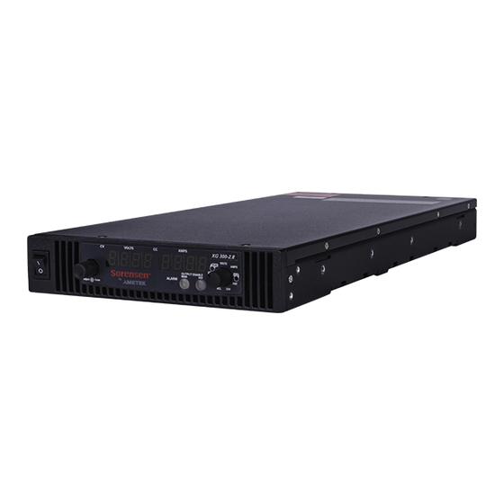
Ametek Sorensen XTR Series Operation Manual (381 pages)
Programmable DC Power Supply 670 Watts – 1700 Watts
Brand:
Ametek
| Category:
Power Supply
| Size: 8 MB
Table of Contents
Table of Contents
9
Contact Information
3
Related Information
6
Important Safety Instructions
7
Table of Contents
20
Table 1-1 Xg/Xtr 850 W
21
Table 1-2 Xg/Xtr 1500 W
21
Table 2-2 Xg/Xtr 1500
21
Table 5-12 Oper Ation
21
Table 5-13 Oper Ation
21
Introduction
23
Features and Options
24
Xg and Xtr Models ( Firmware Version 2.0 and Higher )
25
C Urrent R Anges
25
Table 1-3 Xg/Xtr 1700 W
26
C Urrent R Anges
26
Front Panel
27
Figure 1-1 Xg/Xtr Front Panels
27
Front Panel Display and Controls
28
Figure 1-2 Front Panel Display and Controls
28
Rear Panel Connectors on 850 Watt Models
29
Figure 1-3 Xg/Xtr 850 Watt Units : 6 Vto 40 V Models
29
Figure 1-5 Xg/Xtr 850 Watt Units : 300 Vto 600 V Models
29
Rear Panel Connector on 850 Watt Model
29
Rear Panel Connectors on 1500 and 1700 Watt Models
31
Figure 1-4 Xg/Xtr 850 Watt Units : 60 Vto 150 V Models
29
Figure 1-6 Xg/Xtr 1500 and 1700 Watt Units : 6 Vto 40 V Models
31
Figure 1-7 Xg/Xtr 1500 and 1700 Watt Units : 60 Vto 600 V Models
32
Installation
33
Basic Setup Procedure
34
Step 1: Inspecting and Cleaning
35
Initial Inspection
35
Periodic Cleaning
35
Step 2: Location and Mounting
36
Purchasing Rack Mount Kits
36
Rack Mounting
36
Ventilation
36
Step 3: Connecting Ac Input Power
37
XG/XTR 850 Watt AC Input Connector
37
XG/XTR 1500 and 1700 Watt AC Input Connector
38
XG/XTR 1500 and 1700 Watt AC Input Wire
38
Figure 2-1 1500 and 1700 Watt Ac Input Cover and Strain Relief
38
XG/XTR 1500 and 1700 Watt AC Input Wire Connection
39
Step 4: Selecting Load Wires
40
Current Carrying Capacity
40
Insulation Rating
40
Load Wiring
40
Table 2-3 Currentc
40
Maximum Load Wiring Length for Operation with Sense Lines
41
Noise and Impedance Effects
41
Figure 2-2 Maximum Load Wire Length for 1 V Line Drop
41
Step 5: Performing Functional Tests
42
Powering the Power Supply On/Off
42
Voltage and Current Mode Operation Checks
43
Step 6: Connecting Loads
44
DC Output Connectors
44
Inductive Loads and Batteries
45
Figure 2-3 Diode Placement
45
Connecting Multiple Loads
46
Connecting Single Loads
46
Figure 2-4 Connecting Single Loads
46
Figure 2-5 Remote Sense Connection
47
Step 7: Connecting Remote Sensing
47
Local Operation
49
Introduction
50
Configuring Settings from the Front Panel
50
Using the 9-Position Mode Control
50
Using the Rotary Adjust/Enter Control
50
Figure 3-1 9-Position Mode Control
50
Coarse and Fine Adjustment Modes
51
Panel
51
Navigating the Menu System
53
Setting VOLTS and AMPS Modes
53
Normal Display Mode and Inactivity Timeout
55
Figure 3-2 Front Panel Menu System
56
Display Messages on the Front Panel
57
Table 3-2 Front Panel
57
Text
57
Standard (Local) Operation
60
Operating Modes
60
Figure 3-3 Operating Modes
63
Mode
63
Enabling the Output
65
Shipped Configuration (Local Operation)
65
Enabling the Auxiliary Output
66
Output Auto Start Mode (Auto Restart)
66
Auxiliary Auto Start Mode
67
Constant Power Mode
67
Alarm and Error
69
Recedence
69
Clearing Alarms
70
Front Panel ALARM LED
71
P Ositions
71
Alarm Masking
72
Table 3-5 Alarm Mask
72
Alarm Output Latching
73
Table 3-6 Alarm Latch
73
Alarms and Errors
69
Table 3-4 Alarm Order of
69
Setting Foldback Mode
74
Resetting Activated Foldback Protection
75
Using over Voltage Protection (Ovp)
76
Defining the OVP Set Point
77
Using under Voltage Protection (Uvp)
78
Defining the UVP Set Point
79
Over Current Protection (Ocp)
79
Using over Temperature Protection Lock (Otp)
80
Defining the OTP Mode
80
Resetting in Latch Mode
80
Using the External Shutdown Function
81
Activating the External Shutdown Function
81
Controlling the External Shutdown Function
81
Defining the Polarity of the External Shutdown Signal
82
Loop Protection
82
Setting up Loop Protection
83
Interlock Function
84
Defining the Interlock Mode
84
Output Protection
84
Programming Voltage Output Preset
84
S Ettings
84
Programming Current Output Preset
85
Power on Status Signal
86
Hardware Malfunction Alarms
86
Current Configuration Memory Settings
87
Table 3-7 Power Cycle
87
User Setting Memory Locations
88
Saving User Setting Memory Locations
88
Table 3-8 User Accessible
88
Recalling User Setting Memory Locations
89
Local Lockout
90
Disabling Local Lockout
90
Enabling Local Lockout
90
Resetting the Power Supply
91
Table 3-9 Power Supply
91
Using Multiple Power Supplies
93
Figure 3-4 Split Supply Operation
94
Configuring Multiple Supplies for Series Operation
95
Figure 3-5 Series Operation
96
Figure 3-6 Load Connections in Remote Sensing Mode
97
Configuring Multiple Supplies for Current Sharing Operation (APG Method)
98
Connecting to the Load in Local Sensing Mode (Parallel Control Method)
100
Figure 3-7 Load Connections in Local Sensing Mode
100
Connecting to the Load in Remote Sensing Mode (Parallel Control Method)
101
Figure 3-8 Load Connections in Remote Sensing Mode (Parallel Control Method)
101
Analog Programming (Apg) and Isolated Analog Programming (Isol)
103
Introduction
104
Analog Programming (APG) of Output Voltage and Output Current
104
Line
105
Remote Programming Options
105
Table 4-1 Monitor Lines
105
Table 4-2 Remotep
106
Analog Programming (APG) Connector J1
107
Figure 4-1 Apg Connector Terminals
107
DC O Utput C Onnector
109
S Pring T Erminal B Lock
109
Analog Programming Mode
111
Analog Programming with External Voltage Source
111
Voltage-Controlled Voltage APG Setup
112
Voltage-Controlled Current APG Setup
114
O Utput C Urrent Using an E Xternal R Esistor
116
O Utput V Oltage Using an E Xternal R Esistor
116
Resistive-Controlled Voltage APG Setup
117
Resistive-Controlled Current APG Setup
119
R Eadback U Sing Apg C Onnector J1
121
Voltage and Current Readback
121
Isolated Analog Programming Mode (Isol)
122
AUX Output and Isolated Analog Programming (ISOL) Connector
122
Onnector P ins and F Unctions J3
123
Table 4-4 aux Output and Table 5-1 Remote Control
123
Voltage-Controlled Voltage ISOL Setup
125
Voltage-Controlled Current ISOL Setup
127
Resistive-Controlled Voltage ISOL Setup
130
Resistive-Controlled Current ISOL Setup
132
C Urrent M Onitoring
134
V Oltage M Onitoring
134
Voltage and Current Readback (Isolated)
134
Remote Operation
135
Introduction
136
Hardware and Connection Setup
136
Configuring Remote Control Using RS-232
136
C Ontrol C Onnectors
137
Ins and F Unctions J4 and J61
137
Table 5-2 Db-9 Pinouts
138
C Able with Db-9 P Inout
139
Inouts
139
C Able with Db-25 P Inout
140
C Able with Db-9
141
Configuring Remote Control Using RS-485
141
Inouts
141
Table 5-6 Rj-45 Plugp
141
Unit
142
Configuring Remote Control Using the USB Connector
143
Setting up the PC to Use the USB Connection
143
H Ardware D Evice D Rivers
144
Wizard
144
New Hardware Wizard
145
M Anager
146
P Ort (Com1) P Roperties
147
GPIB Connector (Optional)
149
I Nstruments
151
P Roperties
152
Ethernet/Lan (ENET) Connector (Optional)
153
Multiple Power Supply Connections to RS-485 Bus
153
P Ower S Upply C Onnection to Rs-485 B Us
153
Terminal Configuration
155
Data Format
155
End of Message
155
Hyperterminal
155
Etup
157
Selecting the Appropriate Communication Port
158
Multichannel Address Setting
159
Remote Interface Addressing
160
Multichannel Commands Explained
161
Table 5-8 Rules Form
161
Status Reporting in SCPI
163
R Eporting M Odel
164
S Tandard E Vent S Tatus R Egister
164
Status Registers Model from Ieee 488.2
165
Egister M Odel
165
Status Byte
166
Error/Event Queue (ERR)
166
Questionable Status Register Summary (QSR)
166
Table 5-9 Status Byte
166
Master Summary Status (MSS)
167
Message Available (MAV)
167
Request Service (RQS)
167
Standard Event Status Summary (ESB)
167
Operation Status Register Summary (OSR)
168
Standard Event Status Register (SESR)
169
S Tandard E Vent S Tatus R Egister
170
Table 5-10 Standarde
170
Standard Scpi Register Structure
172
Egister M Odel
172
Operation Status Register
173
S Tatus R Egister F Anout
173
Table 5-11 Oper Ations
174
R Egister
174
S Tatus R Egister
175
Current Share Sub-Register
176
Operation Status Register Commands
177
Current Sharing Sub-Register Commands
178
Shutdown Sub-Register Commands
179
Protection Sub-Register Commands
180
Ques Tionable S Tatus R Egister
181
Tionable R Egisters F Anout
182
Temperature Sub-Register
184
Voltage Sub-Register
184
Questionable Status Register Commands
185
Voltage Status Register Commands
186
Temperature Status Register Commands
187
SCPI Error/Event Queue
188
Reset Command
190
Clear All Status Registers
191
SCPI Preset Status
192
Command Line Help System
193
Locking and Unlocking the Front Panel
196
Auto Sequence Programming
196
Configure Other Protection Mechanisms
203
Foldback Protection
203
Interlock Enable/Disable
204
Loop Protection Enable/Disable
204
Over Temperature Protection
204
Save and Recall
206
Set Analog Programming Level
206
Set Remote Programming Interface
206
Bit Mask
208
Protection Mask (Enable Alarms)
208
Power Saving Control (Sleep Mode, XTR/XG 1700 W Only)
209
Communications Options
211
Introduction
212
Setting up Xg/Xtr 850 Watt Models
212
Basics
212
HUB Plug
213
Enet C Onnector and Led S
214
ENET Cros-Cable
214
Network Topology and Connection
215
N Etwork C Onnection of the C Omputer
216
Roperties D Ialog B Ox
217
P Rotocol (Tcp/Ip) P Roperties D Ialog B Ox
218
Software Installations
218
I Nstaller S Etup W Izard
219
Configuring the Device Using Deviceinstaller
220
Folder Window
220
N Etwork a Dapters
221
Ddress M Essage
222
N Etwork a Dapter
222
D Etails W Indow
224
L Antronix I Nterface
224
Ip S Ettings
225
Xp Ort ® I Nterface
225
Terminal Configuration
226
T Erminal C Onnection
227
D Escription W Indow
228
Erminal W Indow
230
Roperties W Indow
230
Roperties D Ialog B Ox
231
S Ession
233
Yper T Erminal W Indow
233
Advanced Section
234
Network Topology 1: Simple LAN
234
S Ession
234
P Ower S Upplies and T wo C Omputers
235
T Erminal S Ession
236
Network Topology 2: ENET and RS-485 Bus
237
Window
238
RS-485 Communication
240
Troubleshooting for XG/XTR 850W Model with ENET And/Or
240
Setting up Xg/Xtr 1500 and 1700 Watt Models
242
Local Area Network (Lan) Option
242
Communication Configuration
242
LAN Connection
242
Media Access Control (MAC) Address
242
Direct-To-PC Connection
243
Private Network Connection
243
Ametek Lxi Discovery Browser
244
Installing the AMETEK LXI Discovery Browser
244
Using the AMETEK LXI Discovery Browser
251
Ametek Enet Test Utility
252
Installing the AMETEK Enettest Utility
252
Using the AMETEK Ethernet Test Utility
258
Setting Lan Parameters
259
Setting LAN Parameters Via Ethernet
259
Setting LAN Parameters Via Serial or USB Port
259
Setting LAN Parameters Via Web Interface
260
Connecting to a Network
264
Connecting with PC on same Side of Router as Power Supply
265
Connecting with Power Supply Hidden Behind a Router
267
Socket Port Number
269
Instrument Drivers and Application Software
270
System Commands
271
Subsystem Syntax
271
Lxi Compliance
274
Drivers
275
Introduction to the LXI Standard
275
LAN Requirements
275
Remote Procedure Calls (RPC)
275
VXI Discovery
275
Web Page
275
Calibration and Troubleshooting
277
Introduction
278
Main Voltage and Current Calibration Principle
279
Understanding the Problem
279
Step 1: Gain Calibration
280
Step 2: Offset Calibration
280
Step 3: Recalibrate Gain
281
Calibrating the Output Voltage
282
Gain Calibration
282
Offset Calibration
282
Calibrating the Output Current
283
Gain Calibration
283
Offset Calibration
284
Over Voltage Protection Calibration
285
Non-Isolated Analog Programming Calibration
286
Non-Isolated Current Monitoring Calibration
286
Non-Isolated Voltage Monitoring Calibration
286
Non-Isolated Voltage Programming of Voltage Calibration
288
Non-Isolated Resistive Programming of Voltage Calibration
289
Non-Isolated Voltage Programming of Current Calibration
290
Non-Isolated Resistive Programming of Current Calibration
291
Calibration Procedure for Isolated Modes
292
Isolated Voltage Monitoring Calibration
292
Isolated Current Monitoring Calibration
293
Isolated Voltage Programming of Voltage Calibration
294
Isolated Resistive Programming of Voltage Calibration
295
Isolated Voltage Programming of Current Calibration
296
Isolated Resistive Programming of Current Calibration
297
Calibrating the Input Voltage APG Signal
298
Calibrating the Input Current APG Signal
299
Storing and Loading Calibration Parameters
301
Restore Factory Calibration
302
Restore Default Calibration
302
User Diagnostics
302
Emergency Shutdown
303
Unusual or Erratic Operation
303
Troubleshooting for Operators
304
Scpi Command Reference
305
Scpi Conformance Information
306
Codes and Standards
306
IEEE 488.2/SCPI Syntax and Style
306
SCPI Command Hierarchy
307
Using SCPI Commands
308
Parameter Types
311
Scpi Command Tree
312
SCPI Command Summary
318
O Utput C Ontrol
321
C Alibration
322
M Echanisms
325
T Riggering
327
C Ommands
331
Error Messages
341
Error Messages
342
Command Error List
343
R Egisters
343
Execution Error List
344
R Egisters
344
Device-Specific Error List
345
Query Error List
346
Specifications
347
Electrical Specifications for XG/XTR Family, 850 W
348
AC Line Input Specifications for XG/XTR 850 Watt
349
Electrical Specifications for XG/XTR Family, 1500 W
350
AC Line Input Specifications for XG/XTR 1500 Watt
351
Electrical Specifications for XG/XTR Family, 1700 W
352
AC Line Input Specifications for XG/XTR 1700 Watt
353
Remote Operation Programming
354
Common Specifications for All Models
355
All Model
355
Utput C over
362
Iews
363
I Nstallation I Nstructions
367
Rack Mount Kit Options
368
Rack Mount Options and Installation Instructions
368
XG/XTR Single (Half Rack) and Dual (Full Rack
368
Location Requirements
369
Installation Procedures
370
Mounting Option A: 1U Rails
370
Tools and Materials Required
370
Epth
372
Mounting Option B: Manufactured Slides from Jonathan ® Engineered
372
Type.
373
B Racket
374
Rack
376
Index
379
Advertisement
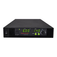
Ametek Sorensen XTR Series Operating Manual (280 pages)
XTR 850 Watt Series Programmable DC Power Supply
Brand:
Ametek
| Category:
Power Supply
| Size: 3 MB
Table of Contents
Power Supply
1
Contact Information
3
Related Information
6
Important Safety Instructions
7
Table of Contents
9
Non-Isolated Voltage Programming of Current Calibration - - - - - - - - - - - - - -
14
Specifications
15
1 Introduction
21
Features and Options
22
XTR 850 Watt Models (Firmware Version 1.11 and Higher)
23
Table 1-1 XTR 850 Watt Series Voltage and Current Ranges
23
Front Panel
24
Figure 1-1 XTR 850 Watt Front Panel
24
Figure 1-2 Front Panel Display and Controls
25
Front Panel Display and Controls
25
Rear Panel Connectors
26
Figure 1-3 Rear Panel: 6 V to 40 V Models
26
Figure 1-4 Rear Panel: 60 V to 150 V Models
26
Figure 1-5 Rear Panel: 300 V to 600 V Models
26
2 Installation
29
Basic Setup Procedure
30
Table 2-1 Basic Setup Procedure
30
Step 1: Inspecting and Cleaning
31
Initial Inspection
31
Periodic Cleaning
31
Step 2: Location and Mounting
32
Rack Mounting
32
Purchasing Rack Mount Kits
32
Ventilation
32
Step 3: Connecting AC Input Power
33
AC Input Connector
33
Step 4: Selecting Load Wires
34
Load Wiring
34
Table 2-2 Current Carrying Capacity for Load Wiring
34
Figure 2-1 Maximum Load Wire Length for 1 V Line Drop
35
Step 5: Performing Functional Tests
36
Powering the Power Supply On/Off
36
Voltage and Current Mode Operation Checks
37
Step 6: Connecting Loads
38
DC Output Connectors
38
Inductive Loads and Batteries
39
Figure 2-2 Diode Placement
39
Connecting Single Loads
40
Connecting Multiple Loads
40
Figure 2-3 Connecting Single Loads
40
Step 7: Connecting Remote Sensing
41
Figure 2-4 Remote Sense Connection
41
3 Local Operation
43
Introduction
44
Configuring Settings from the Front Panel
44
Using the 9-Position Mode Control
44
Using the Rotary Adjust/Enter Control
44
Figure 3-1 9-Position Mode Control
44
Coarse and Fine Adjustment Modes
45
Table 3-1 Select and Set from the Front Panel
45
Navigating the Menu System
47
Setting VOLTS and AMPS Modes
47
Normal Display Mode and Inactivity Timeout
49
Figure 3-2 Front Panel
49
Figure 3-3 Front Panel Menu System
50
Display Messages on the Front Panel
51
Table 3-2 Front Panel Display Text
51
Standard Operation
54
Operating Modes
54
Figure 3-4 Operating Modes
56
Shipped Configuration (Local Operation)
58
Enabling the Output
58
Table 3-3 Shipped Configuration
58
Enabling the Auxiliary Output
59
Output Auto Start Mode (Auto Restart)
59
Auxiliary Auto Start Mode
60
Alarms and Errors
61
Table 3-4 Alarm Order of Precedence
61
Clearing Alarms
62
Front Panel ALARM LED
63
Alarm Masking
64
Table 3-5 Alarm Mask Bit Positions
64
Alarm Output Latching
65
Table 3-6 Alarm Latch Bit Positions
65
Setting Foldback Mode
66
Resetting Activated Foldback Protection
67
Using over Voltage Protection (OVP)
68
Defining the OVP Set Point
69
Using under Voltage Protection (UVP)
70
Defining the UVP Set Point
71
Over Current Protection (OCP)
71
Using over Temperature Protection Lock (OTP)
72
Defining the OTP Mode
72
Resetting in Latch Mode
72
Using the External Shutdown Function
73
Activating the External Shutdown Function
73
Controlling the External Shutdown Function
73
Defining the Polarity of the External Shutdown Signal
74
Interlock Function
75
Defining the Interlock Mode
75
Output Protection
75
Programming Voltage Output Preset
75
Programming Current Output Preset
76
Power on Status Signal
77
Hardware Malfunction Alarms
77
Current Configuration Memory Settings
78
Table 3-7 Power Cycle Saved/Recalled Settings
78
User Setting Memory Locations
79
Saving User Setting Memory Locations
79
Table 3-8 User Accessible Saved/Recalled Settings
79
Recalling User Setting Memory Locations
80
Local Lockout
81
Enabling Local Lockout
81
Disabling Local Lockout
81
Resetting the Power Supply
82
Table 3-9 Power Supply Default Settings
82
Using Multiple Power Supplies
84
Figure 3-5 Split Supply Operation
85
Configuring Multiple Supplies for Series Operation
86
Figure 3-6 Series Operation
86
Figure 3-7 Load Connections in Remote Sensing Mode
87
Configuring Multiple Supplies for Current Sharing Operation (APG Method)
88
Connecting to the Load in Local Sensing Mode (Parallel Control Method)
91
Figure 3-8 Load Connections in Local Sensing Mode
91
Connecting to the Load in Remote Sensing Mode (Parallel Control Method)
92
Figure 3-9 Load Connections in Remote Sensing Mode (Parallel Control Method)
92
4 Analog Programming (APG) and Isolated Analog Programming (ISOL)
95
Introduction
96
Analog Programming (APG) of Output Voltage and Output Current
96
Remote Programming Options
97
Table 4-1 Monitor Lines
97
Table 4-2 Remote Programming Options
98
Analog Programming (APG) Connector J1
99
Figure 4-1 APG Connector Terminals
99
Table 4-3 APG Pins and Functions J1
99
Figure 4-2 Inserting Screwdriver into Spring Terminal Block
101
Figure 4-3 APG and DC Output Connector
101
Analog Programming Mode
103
Analog Programming with External Voltage Source
103
Figure 4-4 Programming Output Voltage Using an External Voltage Source
103
Figure 4-5 Programming Output Current Using an External Voltage Source
103
Voltage-Controlled Voltage APG Setup
104
Voltage-Controlled Current APG Setup
106
Figure 4-6 Programming Output Voltage Using an External Resistor
108
Figure 4-7 Programming Output Current Using an External Resistor
108
Resistive-Controlled Voltage APG Setup
109
Resistive-Controlled Current APG Setup
111
Voltage and Current Readback
113
Figure 4-8 Voltage Readback Using APG Connector J1
113
Figure 4-9 Current Readback Using APG Connector J1
113
Isolated Analog Programming Mode (ISOL)
114
AUX Output and Isolated Analog Programming (ISOL) Connector
114
Figure 4-10 AUX Output and ISOL Connector Pinout
114
Table 4-4 AUX Output and ISOL Connector Pins and Functions J3
115
Figure 4-11 Programming Output Voltage Using an Isolated External Voltage Source
117
Figure 4-12 Programming Output Current Using an Isolated External Voltage Source
117
Voltage-Controlled Voltage ISOL Setup
118
Voltage-Controlled Current ISOL Setup
120
Figure 4-13 Programming Output Voltage Using an Isolated External Resistor
122
Figure 4-14 Programming Output Current Using an Isolated External Resistor
122
Resistive-Controlled Voltage ISOL Setup
123
Resistive-Controlled Current ISOL Setup
125
Voltage and Current Readback (Isolated)
127
Figure 4-15 Isolated Voltage Monitoring
127
Figure 4-16 Isolated Current Monitoring
127
5 Remote Operation
129
Introduction
130
Hardware and Connection Setup
131
Configuring Remote Control Using
131
Figure 5-1 Remote Control Connectors
131
Table 5-1 Remote Control Connector Pins and Functions J4 and J6
131
Table 5-2 DB-9 Pinouts
132
Table 5-3 RJ-45 Pinouts
132
Figure 5-2 RS-232 Communication Cable with DB-9 Pinout
133
Figure 5-3 DB-25 Pinout
133
Table 5-4 DB-25 Pinouts
133
Figure 5-4 RS-232 Communication Cable with DB-25 Pinout
134
Configuring Remote Control Using
135
Table 5-5 DB-9 Pinouts
135
Table 5-6 RJ-45 Plug Pinouts
135
Figure 5-6 RS-485 Communication Cable from Master to Slave Unit
136
Table 5-7 RJ-45 Plug on Slave Unit
136
Configuring Remote Control Using the USB Connector
137
Setting up the PC to Use the USB Connection
137
Figure 5-7 Found New Hardware Wizard
138
Figure 5-8 Install Hardware Device Drivers
138
Figure 5-9 Completing the New Hardware Wizard
139
Figure 5-10 Device Manager
140
Figure 5-11 Communications Port (COM1) Properties
141
Figure 5-12 Completing the New Hardware Wizard
141
Ethernet (ENET) or GPIB Connector (Optional)
143
Multiple Power Supply Connections to RS-485 Bus
143
Figure 5-13 Multi Power Supply Connection to RS-485 Bus
143
Terminal Configuration
145
Data Format
145
End of Message
145
Hyperterminal
145
Figure 5-14 USB Settings
146
Figure 5-15 ASCII Setup
147
Selecting the Appropriate Communication Port
148
Multichannel Address Setting
149
Remote Interface Addressing
150
Multichannel Commands Explained
151
Table 5-8 Rules for Multichannel Responses
151
Status Reporting in SCPI
153
Figure 5-16 SCPI Status Reporting Model
154
Status Registers Model from IEEE 488.2
155
Figure 5-17 IEEE 488.2 Register Model
155
Status Byte
156
Error/Event Queue (ERR)
156
Questionable Status Register Summary (QSR)
156
Table 5-9 Status Byte Summary Register
156
Message Available (MAV)
157
Standard Event Status Summary (ESB)
157
Master Summary Status (MSS)
157
Request Service (RQS)
157
Operation Status Register Summary (OSR)
158
Standard Event Status Register (SESR)
159
Figure 5-18 Summary of Standard Event Status Register
160
Table 5-10 Standard Event Status Register
160
Standard SCPI Register Structure
162
Figure 5-19 SCPI Register Model
162
Operation Status Register
163
Figure 5-20 Operation Status Register Fanout
163
Table 5-11 Operation Status Register
164
Table 5-12 Operation Shutdown Status Register
165
Table 5-13 Operation Shutdown Protection Status Register
165
Current Share Sub-Register
166
Table 5-14 Operation Cshare Status Register
166
Operation Status Register Commands
167
Current Sharing Sub-Register Commands
168
Shutdown Sub-Register Commands
169
Protection Sub-Register Commands
170
Questionable Status Register
171
Table 5-15 Questionable Status Register
171
Figure 5-21 SCPI Questionable Registers Fanout
172
Table 5-16 Questionable Voltage Status Register
174
Table 5-17 Questionable Temperature Status Register
174
Temperature Sub-Register
174
Voltage Sub-Register
174
Questionable Status Register Commands
175
Voltage Status Register Commands
176
Temperature Status Register Commands
177
SCPI Error/Event Queue
178
Reset Command
180
Clear All Status Registers
181
SCPI Preset Status
182
Table 5-18 Preset Values of User Configurable Registers
182
Command Line Help System
183
Locking and Unlocking the Front Panel
186
Auto Sequence Programming
186
Configure Other Protection Mechanisms
193
Foldback Protection
193
Over Temperature Protection
194
Interlock Enable/Disable
194
Save and Recall
195
Set Analog Programming Level
195
Set Remote Programming Interface
195
Protection Mask (Enable Alarms)
197
Table 5-19 Alarms Bit Mask
197
6 Calibration and Troubleshooting
199
Introduction
200
Main Voltage and Current Calibration Principle
201
Understanding the Problem
201
Figure 6-1 Offset (Intercept) Error and Gain (Slope) Error
201
Step 1: Gain Calibration
202
Step 2: Offset Calibration
202
Figure 6-2 Calibration: Step 1 Gain Calibration
202
Figure 6-3 Calibration: Step 2 Offset Calibration
202
Step 3: Recalibrate Gain
203
Figure 6-4 Calibration: Step 3 Recalibrate Gain
203
Calibrating the Output Voltage
204
Gain Calibration
204
Offset Calibration
204
Calibrating the Output Current
205
Gain Calibration
205
Offset Calibration
206
Over Voltage Protection Calibration
207
Non-Isolated Analog Programming Calibration
208
Non-Isolated Voltage Monitoring Calibration
208
Non-Isolated Current Monitoring Calibration
209
Non-Isolated Voltage Programming of Voltage Calibration
210
Non-Isolated Resistive Programming of Voltage Calibration
211
Non-Isolated Voltage Programming of Current Calibration
212
Non-Isolated Resistive Programming of Current Calibration
213
Calibration Procedure for Isolated Modes
214
Isolated Voltage Monitoring Calibration
214
Isolated Current Monitoring Calibration
215
Isolated Voltage Programming of Voltage Calibration
216
Isolated Resistive Programming of Voltage Calibration
217
Isolated Voltage Programming of Current Calibration
218
Isolated Resistive Programming of Current Calibration
219
Calibrating the Input Voltage APG Signal
220
Calibrating the Input Current APG Signal
221
Storing and Loading Calibration Parameters
223
Restore Factory Calibration
224
Restore Default Calibration
224
User Diagnostics
224
Emergency Shutdown
225
Unusual or Erratic Operation
225
Troubleshooting for Operators
226
Table 6-1 Troubleshooting
226
A SCPI Command Reference
227
SCPI Conformance Information
228
IEEE 488.2/SCPI Syntax and Style
228
SCPI Command Hierarchy
229
Using SCPI Commands
230
Parameter Types
233
SCPI Command Tree
234
SCPI Command Summary
240
Table A-1 IEEE 488.2 Commands
240
Table A-2 Readback Commands
242
Table A-3 SCPI Commands for Output Control
243
Table A-4 SCPI Commands for Calibration
244
Table A-5 SCPI Commands to Clear All Protection Mechanisms
247
Table A-6 SCPI Commands for Foldback Protection
247
Table A-7 SCPI Commands for Power
248
Table A-8 SCPI Commands for Triggering
248
Table A-9 System Commands
249
Table A-10 Status Commands
252
Table A-12 Auto Sequence Commands
259
Table A-11 Protection Commands
259
Error Messages
263
Error Messages
264
Command Error List
265
Table B-1 Command Error List
265
Execution Error List
266
Table B-2 Execution Error List
266
Device-Specific Error List
267
Table B-3 Device-Specific Error List
267
Query Error List
268
Table B-4 Query Error List
268
100 C Specifications
270
Electrical Specifications for XTR 850 Watt
270
Table C-1 XTR 850 Watt Electrical Specifications for 6 V to 600 V Models
270
AC Line Input Specifications for XTR 850 Watt
271
Remote Operation
272
Table C-2 Remote Operation
272
Common Specifications for All Models
273
Figure C-1 XTR 850 Watt Mechanical Dimensions: 6 to 40 V Models
275
Figure C-2 XTR 850 Watt Mechanical Dimensions: 60 V to 600 V Models
276
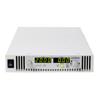
Ametek Sorensen XTR Series Quick Reference Quide (2 pages)
850 Watt Programmable DC Power Supply
Brand:
Ametek
| Category:
Power Supply
| Size: 0 MB
Table of Contents
XTR Front Panel Controls, Displays, and Indicators
1
General Procedures for Setting up Features
1
Setting the Output Voltage and Current Limit Using Tracking Mode
1
Front Panel Menu System (Firmware V1.09 and Below)
2
Front Panel Display Messages
2
Legend
2
Advertisement
Advertisement
Related Products
Ametek Sorensen XTR
Ametek Sorensen XT Series
Ametek Sorensen XTR6-110
Ametek Sorensen XTR60-14
Ametek Sorensen XTR8-100
Ametek Sorensen XTR80-10.5
Ametek Sorensen XTR12-70
Ametek Sorensen XTR100-8.5
Ametek Sorensen XTR20-42
Ametek Sorensen XTR150-5.6
Ametek Categories
Measuring Instruments
Test Equipment
Power Supply
Switch
Controller
More Ametek Manuals
Login
Sign In
OR
Sign in with Facebook
Sign in with Google
Upload manual
Upload from disk
Upload from URL