
Related Manuals for Ametek Sorensen XPF Series


Summary of Contents for Ametek Sorensen XPF Series
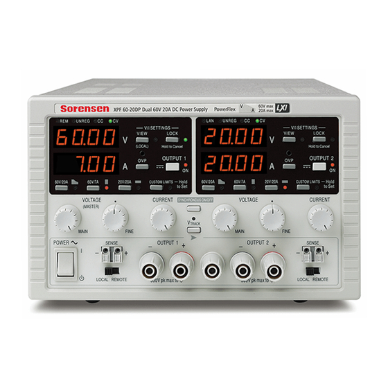
- Page 1 XPF Series Dual Output 60V 20A Powerflex DC Power Supply Operation Manual Model: XPF 60-20D & DP M370417-01 Rev F www.programmablepower.com...
- Page 2 About AMETEK AMETEK Programmable Power, Inc., a Division of AMETEK, Inc., is a global leader in the design and manufacture of precision, programmable power supplies for R&D, test and measurement, process control, power bus simulation and power conditioning applications across diverse industrial segments.
-
Page 3: Table Of Contents
Table of Contents Specification Safety Installation Connections Manual Operation Remote Interface Operation (XPF60-20DP only) Remote Commands (XPF60-20DP only) Calibration Maintenance Instructions en Francais Sécurité Installation Connexions Fonctionnement manuel Fonctionnement de l’interface de commande à distance (XPF60-20DP uniquement) Commandes à distance (XPF60-20DP uniquement) Maintenance Bedienungsanleitung auf Deutsch Sicherheit... - Page 4 Instrucciones en Español Seguridad Instalación Conexiones Manejo manual Manejo de la interfaz remota (solo XPF60-20DP) Comandos remotos (solo XPF60-20DP) Mantenimiento Warranty Information...
-
Page 5: Specification
Specification General specifications apply for the temperature range 5°C to 40°C. Accuracy specifications apply for the temperature range 18°C to 28°C after 1 hour warm-up with no load and calibration at 23°C. Typical specifications are determined by design and are not guaranteed. OUTPUT SPECIFICATIONS Voltage Range: 0V to 60V... - Page 6 Over-temperature The output will be tripped off if a fault causes the internal temperature to rise Protection: excessively. Line Regulation: Change in output for a 10% line change: Constant voltage: <0.01% of maximum output Constant current: <0.01% of maximum output Load Regulation: Change in output for any load change within PowerFlex envelope, remote sense connected:...
-
Page 7: Safety
DIGITAL INTERFACES (XPF60-20DP only) Full digital remote control facilities are available through the RS232, USB, LAN and GPIB interfaces. Voltage Setting: 16-bit, Resolution 10mV, Accuracy ± (0·05% +10mV) Current Setting: 16-bit, Resolution 1mA, Accuracy ± (0·3% + 0·005A) RS232: Standard 9-pin D-connector. Baud rate 9600. GPIB: Conforming with IEEE488.1 and IEEE488.2 USB:... - Page 8 Safety This power supply is a Safety Class I instrument according to IEC classification and has been designed to meet the requirements of EN61010-1 (Safety Requirements for Electrical Equipment for Measurement, Control and Laboratory Use). It is an Installation Category II instrument intended for operation from a normal single phase supply.
-
Page 9: Installation
Installation Mains Operating Voltage This instrument has a universal input range and will operate from a nominal 115V or 230V mains supply without adjustment. Check that the local supply meets the AC Input requirement given in the Specification. Mains Lead Connect the instrument to the AC supply using the mains lead provided. -
Page 10: Connections
Connections Front Panel Connections The load should be connected to the positive (red) and negative (black) terminals marked OUTPUT. The OUTPUT terminals are rated at 30A. Remote sense connections to the load, if required, are made from the positive (+) and negative (−) SENSE terminals. - Page 11 Rear Panel Connections (XPF60-20DP only) The output and sense terminals for OUTPUT1 and OUTPUT2 are duplicated on the rear panel terminal blocks and are marked +O/P, −O/P, +S and −S. These connections are paralleled with their front panel equivalents. Switch the LOCAL/REMOTE switch to REMOTE when remote sensing is required. When the rear panel Output terminals are used, the use of remote sense is always recommended to ensure that output regulation is maintained within specification;...
- Page 12 recognize that the instrument has been connected. If the correct driver is not found, follow the Windows on-screen prompts and install the required files from the CD supplied. LAN (XPF60-20DP only) The LAN interface is designed to meet LXI ( Lan eXtensions for Instrumentation) version 1.2; the instrument is Class C compliant.
-
Page 13: Manual Operation
Manual Operation The operation of both outputs is identical; the following description applies to both. Switching On The power switch, located at the bottom left of the front panel, switches between standby ( and on ( l ). In standby the auxiliary power circuit remains connected and consumes ~6 Watts. To fully disconnect from the AC supply unplug the mains cord from the back of the instrument or switch off at the AC supply outlet;... - Page 14 The CUSTOM LIMITS capability allows the maximum values of both the VOLTAGE and CURRENT controls to be redefined by the user such that the controls operate over specific, lower, ranges. This not only has the advantage of protecting against the accidental application of, for example, excess voltages to the load, but also provides higher resolution analogue control over the specified ranges using the full 300º...
- Page 15 The power envelope is set to give 60V/7A, 42V/10A and 20V / 20A under all supply conditions (both outputs loaded); at lower output voltages the output power is restricted by the 20A current maximum. When the power limit is exceeded, the status indication will change from CV or CC to UNREG. For example, if the supply is set to 20V, with the current limit at maximum, and is connected to a 2Ω...
- Page 16 It should be noted that the unit can only source current and cannot sink it, thus units cannot be series connected in anti-phase. The unit can be connected in parallel with others to produce higher currents. Where several units are connected in parallel, the output voltage will be equal to that of the unit with the highest output voltage setting until the current drawn exceeds its current limit setting, upon which the output will fall to that of the next highest setting, and so on.
- Page 17 Lock Settings Pressing the LOCK key digitally locks the set voltage and current limit. The settings are stored with a precision of better than 1 digit. Subsequent adjustments of the VOLTAGE and CURRENT controls will have no effect. Because cancelling LOCK will cause the output settings to change if the VOLTAGE and CURRENT control positions have been moved, warning reminders are given before LOCK is cancelled.
- Page 18 Synchronous Output On/Off Control The SYNCHRONOUS ON/OFF key is in addition to the individual OUTPUT switches and permit both outputs to be turned on or off synchronously with a single key press. Since this key turns both outputs on or off with alternate presses it is necessary for both outputs to be in the same state (i.e.
-
Page 19: Remote Interface Operation (Xpf60-20Dp Only)
Remote Interface Operation (XPF60-20DP only) The instrument can be remotely controlled via its RS232, USB, LAN or GPIB interfaces. USB remote control operates in a similar way to RS232 but via the USB connector. Software supplied with the instrument sets up the controlling computer to treat the USB connection as a virtual COM port. - Page 20 Remote/Local Operation At power-on the instrument will be in the local state with the REMote indicator off. In this state all front panel operations are possible. When the instrument is addressed to listen and a command is received the remote state will be entered and REMote will be turned on. In this state the front panel is locked out and remote commands only will be processed.
- Page 21 Baud Rate for this instrument is fixed at 9600; the other parameters are fixed as follows: Start Bits: 1 Parity: None Data Bits: 8 Stop Bits: 1 RS232 Character Set Because of the need for XON/XOFF handshake it is possible to send ASCII coded data only; binary blocks are not allowed.
- Page 22 Use can also be made of the ADDRESS? command to easily identify which instrument is being controlled by a particular COM port. Although the addressing capability is ignored in USB operation the address can still be set and used as an identifier; set each USB-connected instrument to a different address and send the ADDRESS? command from each virtual COM port to confirm which instrument is connected to that port.
- Page 23 VXI-11 Discovery Protocol The instrument has very limited support of VXI-11 which is sufficient for the discovery protocol and no more. The instrument implements a Sun RPC Port-mapper on TCP port 111 and UDP port 111 as defined in RPC1183. The calls supported are: NULL, GET PORT and DUMP. On TCP port 1024 a very simple VXI-11 protocol is implemented sufficient only for instrument discovery.
- Page 24 GPIB Interface The GPIB interface 24-way connector is located on the instrument rear panel. The pin connections are as specified in IEEE Std. 488.1-1987 and the instrument complies with IEEE Std. 488.1-1987 and IEEE Std. 488.2-1987. GPIB Subsets This instrument contains the following IEEE 488.1 subsets: Source Handshake Acceptor Handshake Talker...
- Page 25 Poll Configure command (PPC) followed by a Parallel Poll Enable command (PPE). The bits in the PPE command are shown below: bit 7 = don't care bit 6 = bit 5 = Parallel poll enable bit 4 = bit 3 = Sense sense of the response bit;...
- Page 26 Bit 3: Verify Timeout Error. Set when a parameter is set with 'verify' specified and the value is not reached within 5 seconds, e.g. output voltage is slowed by a large capacitor on the output. Bit 2: Query Error. Set when a query occurs. The appropriate error number will be reported in the Query Error Register, see Query Error Register section.
- Page 27 Status Byte Register and Service Request Enable Register These two registers are implemented as required by the IEEE Std. 488.2. Any bits set in the Status Byte Register which correspond to bits set in the Service Request Enable Register will cause the RQS/MSS bit to be set in the Status Byte Register, thus generating a Service Request on the bus.
- Page 28 Status Model...
- Page 29 Power-on and Remote Operation Default Settings The following instrument status values are set at power on: Status Byte Register Service Request Enable Register † Standard Event Status Register = 128 (pon bit set) Standard Event Status Enable Register † Execution Error Register Query Error Register Parallel Poll Enable Register †...
-
Page 30: Remote Commands (Xpf60-20Dp Only)
Remote Commands (XPF60-20DP only) RS232/USB Remote Command Format RS232 input to the instrument is buffered in a 256 byte input queue which is filled, under interrupt, in a manner transparent to all other instrument operations. The instrument will send XOFF when approximately 200 characters are in the queue. - Page 31 Each query produces a specific which is listed along with the command in <RESPONSE MESSAGE> the remote commands list. is ignored except in command identifiers. e.g. '*C LS' is not equivalent to '*CLS'. <WHITE SPACE> is defined as character codes 00H to 20H inclusive with the exception of the NL <WHITE SPACE>...
- Page 32 OVP<n>? Returns the voltage trip setting for output <n> The response is VP<n> <nr2><rmt> where <nr2> is in Volts OCP<n>? Returns the current trip setting for output <n> The response is CP<n> <nr2><rmt> where <nr2> is in Amps V<n>O? Returns the output readback voltage for output <n> The response is <nr2>V<rmt>...
- Page 33 LSR<n>? Query and clear Limit Event Status Register <n>. The response is <nr1><rmt>. See Status Reporting section for details. LSE<n> <nrf> Set the value of LSE<n>, Limit Event Status Enable Register <n>, to <nrf> LSE<n>? Return the value of LSE<n>, Limit Event Status Enable Register <n> - response is <nr1><rmt>...
- Page 34 *RST Resets the instrument to the remote control default settings with the exception of all remote interface settings and Output state at power-on setting. (see Remote Operation Defaults paragraph in the Remote Interface Operation section) *SRE <nrf> Set the Service Request Enable Register to <nrf>. *SRE? Returns the value of the Service Request Enable Register in <nr1>...
-
Page 35: Calibration
Calibration Routine calibration is carried out without opening the instrument. Allow a 5 minutes warm-up before commencing calibration. Equipment Required A 5½ digit multimeter with better than 0.05% accuracy on dc Volts and better than 0.12% accuracy on dc current to 10 Amps; alternatively use a precision shunt for current measurement. Rheostat or other high power load arrangement to provide up to full load. - Page 36 Step Settings Display Adjust for Load Detail −5mV ± 2mV O/P off Cal count O/P off volts Cal count 0V ± 2mV DAC zero Max V, 1A Cal count 60V ±2mV DAC scale Max V, 1A O/P volts Display = DVM metering scale Max V, 1A OVP setting...
-
Page 37: Maintenance
Maintenance The Manufacturers or their agents overseas will provide repair for any unit developing a fault. Where owner wish to undertake their own maintenance work, this should only be done by skilled personnel in conjunction with the service manual which may be purchased directly from the Manufacturers or their agents overseas. -
Page 38: Sécurité
Sécurité Cet instrument est de Classe de sécurité 1 suivant la classification IEC et il a été construit pour satisfaire aux impératifs EN61010-1 (impératifs de sécurité pour le matériel électrique en vue de mesure, commande et utilisation en laboratoire). Il s'agit d'un instrument d'installation Catégorie II devant être exploité... -
Page 39: Installation
Installation Tension d’utilisation secteur Cet instrument a une plage d'entrée universelle et il fonctionne sur une alimentation secteur de 115 V ou de 230 V, tension nominale, sans ajustement aucun. Vérifier que l'alimentation locale satisfait aux impératifs d'entrée c.a. indiqués aux Caractéristiques techniques. Câble secteur Branchez cet instrument sur l’alimentation secteur en utilisant le câble d’alimentation fourni. -
Page 40: Connexions
Connexions Connexions du panneau avant La charge devra être connectée aux bornes positive (rouge) et négative (noire) marquées OUTPUT (sortie). Les bornes de sortie OUTPUT sont calibrées à 30 A. Les connexions de détection à distance sur la charge, si nécessaire, sont réalisées à partir des bornes positive (+) et négative (−) SENSE (détection). - Page 41 Connexions du panneau arrière (XPF60-20DP uniquement) Les bornes de sortie et de détection pour OUTPUT1 et OUTPUT2 sont doublées sur les répartiteurs du panneau arrière et sont appelées +O/P, −O/P, +S and −S. Ces connexions sont en parallèle avec leurs équivalents du panneau avant. Positionner le commutateur LOCAL/REMOTE sur REMOTE lorsque la fonction de détection à...
- Page 42 USB (XPF60-20DP uniquement) Le port USB est connecté à la masse de l’appareil. Il est compatible avec le standard USB 2.0 (Full Speed) et accepte les câbles USB standard. La fonction « Plug & Play » de Windows devrait automatiquement reconnaître que l’appareil a été connecté. Si le bon pilote n’est pas détecté, suivez les instructions Windows à...
-
Page 43: Fonctionnement Manuel
Fonctionnement manuel Le fonctionnement des deux sorties est identique ; la description suivante s'applique donc aux deux sorties. Mise en marche Le commutateur d'alimentation, situé en bas à gauche du panneau avant, permet d’alterner entre l’état de veille ( ) et l’état de marche ( l ) de l’appareil. Lorsque l’appareil est en veille, le circuit d’alimentation auxiliaire reste connecté... - Page 44 Gamme PowerFlex qui limite l'intensité maximale à la tension réglée à celle déterminée par l’enveloppe de puissance ou 20 A, choisissant la valeur la plus faible. Voir Hold le paragraphe Limite de Puissance plus loin to Set dans ce chapitre. Le fonctionnement normal des gammes 60 V/7 A et 20 V/20 A est tel qu'il est possible d'utiliser la Tension Constante (CV) sur l'ensemble de la gamme de tension, à...
- Page 45 Sortie d’intensité instantanée La commande de limite d’intensité peut être réglée pour limiter l’intensité de sortie continue à des niveaux descendant jusqu’à 10 mA. Cependant, communément à tous les générateurs de précision d’établi, un condensateur est connecté sur la sortie pour conserver la stabilité et une bonne réponse aux défauts transitoires.
- Page 46 Ceci nécessite de connecter les bornes de détection à la sortie sur la charge plutôt que sur la source ; insérer les fils dans les bornes à ressort SENSE (détection) et les connecter directement à la charge. Régler le commutateur LOCAL/REMOTE sur REMOTE. Pour éviter toute instabilité et problème de réponse transitoire, il convient de prendre soin de réaliser un bon couplage entre chaque fil de sortie et de détection, en faisant tourner les fils l‘un autour de l’autre ou en utilisant un câble coaxialement blindé...
- Page 47 La protection contre les surintensités (OCP) est exécutée dans le microprogramme et ne peut être réglée et utilisée que dans le cadre d’un fonctionnement par commande à distance à l‘aide d’une interface RS232, USB, LAN (LXI) ou GPIB (XPF60-20DP uniquement). La résolution de réglage est 10 mA et le temps de réponse typique 500 ms.
- Page 48 Il est interdit d’essayer de sélectionner une gamme différente lorsque LOCK est activé ; si une telle tentative est faite, le message Unloc apparaît brièvement et le voyant lumineux LOCK clignote également. Si la sortie est également activée lorsque ces actions sont tentées, le message (éteindre) apparaît en premier lieu à...
-
Page 49: Fonctionnement De L'interface De Commande À Distance (Xpf60-20Dp Uniquement)
Fonctionnement de l’interface de commande à distance (XPF60-20DP uniquement) Il est possible de commander l'appareil à distance par le biais des interfaces RS232, USB, LAN ou GPIB. La télécommande USB fonctionne de la même manière que pour l’utilisation d’une interface RS232, mais par l’intermédiaire du connecteur USB. - Page 50 L'adresse peut être décrémentée et incrémentée avec les touches VIEW et LOCK respectivement dans la plage allant de 1 à 31 inclus (pas 0), avec 'wrap-round' (mettre à cheval). L'adresse est confirmée et le processus terminé en maintenant la touche Lock enfoncée. L'écran affiche et la nouvelle adresse pendant environ 2 secondes, puis retourne à...
- Page 51 Jeu de caractères RS232 En raison de la nécessité d’un protocole XON/XOFF, il n’est possible de transmettre que des données en code ASCII ; les blocs binaires ne sont pas admis. Le bit 7 des codes ASCII est ignoré, c'est-à-dire qu’il est supposé bas. Aucune distinction n’est faite entre les majuscules et les minuscules pour les mnémoniques de commande et on peut les mélanger librement.
- Page 52 Connexion LAN Pour utiliser l’interface LAN, il est nécessaire de connaître l’adresse IP de l’appareil. Le CD-ROM fourni contient un outil de découverte LXI Discovery Tool qui peut être utilisé pour afficher les adresses IP (et autres informations associées) de tous les appareils connectés conformes au protocole de découverte VXI-11.
- Page 53 Lorsqu’un lien a été créé, toute donnée écrite sur l’appareil est ignorée et toute lecture de l’appareil renvoie la chaîne d’identification comme attendu d'une commande “*IDN?” du formulaire. ‘Fabricant,Modèle,No. de Série,X.xx – Y.yy’ par exemple SORENSEN,XPF60-20DP,279730,1.00 – 1.00 où ‘X.xx’ est la version du microprogramme principal et ‘Y.yy’ la version du microprogramme de l’interface.
- Page 54 Interface GPIB Le connecteur 24 voies de l’interface GPIB se trouve sur le panneau arrière de l’appareil. Les connexions des broches sont conformes à la norme IEEE 488.1-1987 et l'appareil est conforme aux normes IEEE 488.1-1987 et IEEE 488.2-1987. Sous-ensembles GPIB Cet instrument contient les sous-ensembles IEEE 488.1 suivants : Source Handshake (établissement de liaison avec l'émission) Acceptor Handshake (acceptation de liaison)
- Page 55 Scrutation parallèle GPIB Ce générateur dispose de capacités complètes de scrutation parallèle. Le Parallel Poll Enable Register (registre d’activation de scrutation parallèle) est reglé pour spécifier les bits du Status Byte Register (registre d’octets d’état) qui doivent être utilisés pour constituer le message local Le Parallel Poll Enable Register est réglé...
- Page 56 Il s’agit d’un champ de bit dans lequel chaque bit à un sens particulier. Bit 7: Mise sous tension. Réglé lors de la première mise sous tension de l’appareil. Bit 6: Requête Utilisateur (Non utilisé). Bit 5: Erreur de commande. Réglé lorsqu’une erreur de type syntaxique est détectée dans une commande provenant du bus.
- Page 57 Limit Event Status et Limit Event Status Enable Registers (Registres d'état d'événement limite et d'activation d'état d'événement limite) Il existe un Event Status Register Limite pour les alimentations électriques de sortie unique ; il y en a deux pour les alimentations électriques doubles (sauf en cas de fonctionnement en mode parallèle).
- Page 58 Modèle de Statut...
- Page 59 Réglages par défaut de démarrage et de commande à distance Les valeurs suivantes d'état d'instrument sont réglées lors de la mise en marche : Status Byte Register (registre d’octets d’état) Service Request Enable Register (registre d'activation d'état d'événement standard)† Standard Event Status Register = 128 (bit réglage au démarrage) (registre d'état d'événement standard) Standard Event Status Enable Register...
-
Page 60: Commandes À Distance (Xpf60-20Dp Uniquement)
Commandes à distance (XPF60-20DP uniquement) Format de commande à distance RS232/USB L'entrée RS232 de l'appareil est mise en tampon dans une file d'attente d'entrée de 256 octets remplie, sous interruption, de manière transparente à toutes les autres opérations de l'appareil. L'appareil transmettra un signal XOFF lorsque environ 200 caractères se trouvent dans la file d'attente. - Page 61 Les réponses de l'appareil au contrôleur sont transmises en tant que <RESPONSE MESSAGES> (messages de réponse). Un est constitué d'un <RESPONSE MESSAGE> <RESPONSE MESSAGE UNIT> (unité de message de réponse) suivi d'un > (terminaison de <RESPONSE MESSAGE TERMINATOR message de réponse). est le caractère de nouvelle ligne avec le message <RESPONSE MESSAGE TERMINATOR>...
- Page 62 V<n> <nrf> Règle la sortie <n> sur <nrf> Volts. V<n>V <nrf> Règle la sortie <n> sur <nrf> Volts avec vérification. OVP<n> <nrf> Règle le point de déclenchement de protection de surtension de la sortie <n> sur <nrf> Volts. I<n> <nrf> Règle la limite d’intensité...
- Page 63 OP<n>? Renvoie le statut on/off de la sortie <n>. La réponse est <nr1><rmt> où 1 = ON (activé), 0 = OFF (désactivé). TRIPRST Tente de supprimer toutes les conditions de déclenchement. LOCAL Passe en local. Cela ne débloque aucun verrou d’interface actif de sorte que le verrou reste avec l’interface sélectionnée lorsque la commande à...
- Page 64 Commandes système et commandes d’état *CLS Clear Status. Vidage de la structure d’état. Cette fonction vide indirectement le Status Byte Register. EER? Interroge et vide l'Execution Error Register. Format de la réponse : nr1<rmt>. *ESE <nrf> Réglage du Standard Event Status Enable Register sur la valeur <nrf> *ESE? Renvoi de la valeur du Standard Event Status Enable Register au format numérique <nr1>.
- Page 65 Commandes diverses *IDN? Renvoie l’identification de l’appareil. La réponse exacte est déterminée par la configuration de l'appareil et elle est sous forme <NOM>,<modèle>, <No. de série>, <version><rmt> où <NOM> est le nom du constructeur, <modèle> définit le type d'appareil, <No. de série> le numéro de série unique et <version> le niveau de révision du logiciel installé.
-
Page 66: Maintenance
Maintenance Le fabricant ou ses agences à l’étranger proposent un service de réparation pour tout appareil défaillant. Si le propriétaire de ce matériel souhaite en effectuer l’entretien par leurs propres moyens, il est fortement recommandé que ce travail soit effectué exclusivement par un personnel qualifié, à... -
Page 67: Sicherheit
Sicherheit Dieses Gerät wurde nach der Sicherheitsklasse (Schutzart) I der IEC-Klassifikation und gemäß den europäischen Vorschriften EN61010-1 (Sicherheitsvorschriften für elektrische Mess-, Steuer, Regel- und Laboranlagen) entwickelt. Es handelt sich um ein Gerät der Installationskategorie II, das für den Betrieb mit einer normalen einphasigen Versorgung vorgesehen ist. Das Gerät wurde gemäß... -
Page 68: Installation
Installation Netzbetriebsspannung Das Gerät besitzt einen universellen Eingangsbereich und kann ohne jede weitere Einstellung mit einer Nenn-Netzversorgung von 115 oder 230 V betrieben werden. Stellen Sie sicher, daß die Versorgung am Ort den in der Spezifikation aufgeführten Eingangsanforderungen entspricht. Netzkabel Schließen Sie das Instrument unter Verwendung des mitgelieferten Netzkabels an die Wechselstromversorgung an. -
Page 69: Anschlüsse
Anschlüsse Anschlüsse auf der Gerätevorderseite Die Last sollte an die mit OUTPUT (Ausgang) gekennzeichneten positiven (roten) und negativen (schwarzen) Klemmen angelegt werden. Die Ausgangsklemmen (OUTPUT) sind für einen maximalen Strom von 30 A ausgelegt. Die Fernfühleranschlüsse für die Last (falls gewünscht) erfolgen über die entsprechenden Plus- (+) und Minus- ( ... - Page 70 Anschlüsse auf der Geräterückseite (nur XPF 60-20DP) Die Ausgangs- und Fernfühlerklemmen für OUTPUT1 und OUTPUT2 liegen auf der Geräterückseite im Duplikat vor. Diese Anschlüsse sind mit +O/P, −O/P, +S und −S gekennzeichnet und mit ihren Äquivalenten auf der Gerätefront parallel geschaltet. Setzen Sie den Schalter LOCAL/REMOTE auf REMOTE, wenn die Fernfühlerfunktion eingesetzt werden soll.
- Page 71 USB (nur XPF60-20DP) Der USB-Port ist an die Geräteerde angeschlossen. Er entspricht USB 2.0 (Full Speed) und akzeptiert ein standardmäßiges USB-Kabel. Die Plug-and-Play-Funktion von Windows sollte automatisch erkennen, dass das Gerät angeschlossen worden ist. Falls der korrekte Treiber nicht gefunden wird, befolgen Sie bitte die Windows-Aufforderungen auf dem Bildschirm und installieren Sie die benötigten Dateien von der mitgelieferten CD.
-
Page 72: Manueller Betrieb
Manueller Betrieb Die Funktion beider Ausgänge ist identisch. Daher trifft folgende Beschreibung auf beide zu. Einschalten Der Netzschalter befindet sich unten links auf der Gerätevorderseite und schaltet zwischen Standby ( ) und Ein ( l ). Im Standby bleibt der Nebenstromkreis angeschlossen und verbraucht ~6 Watt. - Page 73 Der PowerFlex Bereich begrenzt den Maximalstrom bei der jeweils eingestellten Spannung auf die Leistungsgrenze oder auf 20 A, je nachdem welcher niedriger ist (siehe Abschnitt zur Leistungsbegrenzung weiter unten). Die Bereiche 60V/7A und 20V/20A arbeiten wie gewohnt, so dass ein Konstantspannungsbetrieb (CV) über den gesamten Spannungsbereich möglich ist, vorausgesetzt der Laststrom liegt unter dem Maximalwert für den jeweiligen Bereich.
- Page 74 Momentanstrom Mit Hilfe der Strombegrenzungsfunktion kann der Dauerausgangsstrom bis auf 10 mA herab begrenzt werden. Wie bei allen Präzisionsnetzgeräten wird jedoch auch hier ein Kondensator am Ausgang parallel geschaltet, um eine stabile Ausgangsspannung und ein gutes dynamisches Verhalten zu gewährleisten. Dieser Kondensator lädt sich bis zur Höhe der Ausgangsspannung auf und erzeugt beim Kurzschließen des Ausgangs durch seine Entladung einen Stromimpuls, auf den die Strombegrenzung keinen Einfluss hat.
- Page 75 Anschlusskabel mit großem Querschnitt einschränken, es ist aber besser, diesen Effekt mit Hilfe der Fernfühlerfunktion ganz zu umgehen. Dazu müssen die Fernfühlerklemmen (Sense) an der Last anstelle der Spannungsquelle angeschlossen werden. Schließen Sie die Kabel an die Federklemmen des SENSE-Anschlusses und direkt an der Last an.
- Page 76 OCP (Überstromschutz) ist in der Firmware implementiert und kann nur eingerichtet und verwendet werden, wenn eine Fernsteuerung über die Schnittstellen RS232, USB, LAN (LXI) oder GPIB stattfindet (nur XPF60-20DP). Die Einstellung erfolgt in Schritten von 10 mA mit einer typischen Ansprechzeit von 500 ms. Im lokalen Modus und beim XPF60-20D ist OCP weiterhin aktiv, stellt sich aber automatisch auf 22 Ampere ein.
- Page 77 Beim Loslassen der Taste LOCK, während das Display blinkt, wird die Deaktivierung der LOCK Funktion abgebrochen. Die Wahl eines anderen Bereichs bei aktiviertem LOCK ist nicht möglich. In diesem Fall erscheint kurz die Meldung im Display und die LOCK Lampe blinkt. Wird ein solcher Versuch bei Unloc eingeschaltetem Ausgang unternommen, erscheint zunächst die Meldung turn oFF im Display (zusammen mit blinkender Ausgangslampe), gefolgt von der Meldung Unloc (mit blinkender...
-
Page 78: Ferngesteuerter Betrieb (Nur Xpf60-20Dp)
Ferngesteuerter Betrieb (nur XPF60-20DP) Das Gerät kann über seine RS232-, USB-, LAN- oder GPIB-Schnittstellen ferngesteuert werden. Die USB-Fernsteuerung funktioniert ähnlich wie bei der RS232 Schnittstelle, jedoch über den USB-Anschluss. Die mit dem Gerät gelieferte Software richtet den steuernden Computer darauf ein, den USB-Anschluss als virtuellen COM-Port zu behandeln. - Page 79 Ferngesteuerter/Lokaler Betrieb Nach dem Einschalten befindet sich das Gerät im Modus Lokalbetrieb, die REMOTE Anzeige leuchtet nicht. In diesem Zustand sind alle Einstellungen auf der Gerätevorderseite möglich. Wird das Gerät per Schnittstelle angesteuert und ein Befehl empfangen, schaltet das Gerät auf Fernbedienung und REMOTE wird aktiviert.
- Page 80 Die Baud-Rate ist für dieses Gerät mit 9600 festgelegt, die anderen Parameter haben folgende Werte: Startbits: 1 Parität: keine Datenbits: 8 Stoppbits: 1 RS232-Zeichensatz Aufgrund des erforderlichen XON/XOFF-Protokolls stehen zur Datenübertragung nur ASCII- kodierte Zeichen zur Verfügung, binäre Blöcke sind nicht zulässig. Bit 7 des ASCII-Codes wird ignoriert, d.h.
- Page 81 Verbindung mit demselben virtuellen COM-Port unabhängig vom physikalischen USB-Port, an den es angeschlossen ist. Der Befehl ADDRESS? kann ebenfalls zur einfachen Identifizierung des von einem bestimmten COM-Port gesteuerten Geräts verwendet werden. Obwohl die Adressierungsfähigkeit beim USB- Betrieb ignoriert wird, kann die Adresse weiterhin eingestellt und als Kennung verwendet werden. Stellen Sie jedes USB-verbundene Gerät auf eine unterschiedliche Adresse und schicken Sie den ADDRESS?-Befehl von jedem virtuellen COM-Port zur Bestätigung des an den Port angeschlossenen Geräts.
- Page 82 Auf der eigentlichen Konfigurationsseite wird erklärt, wie das Passwort gesetzt werden kann. Das Passwort darf bis zu 15 Zeichen lang sein. Beachten Sie, dass der Benutzername (User Name) leer bleiben muss. Beim Zurücksetzen aller LAN-Parameter auf die Werksvoreinstellung über den LAN RESET Schalter auf der Geräterückseite wird auch das Passwort auf die Standardeinstellung (kein Passwort) zurückgesetzt.
- Page 83 TCP Sockets Das Gerät verwendet 2 Sockets auf TCP Port 9221 für die Gerätesteuerung und Überwachung. An diesen Port werden die im Abschnitt ‘Fernsteuerbefehle’ beschriebenen Befehle gesendet. Die Antwort erfolgt über den gleichen Port. Eine Zeichenkette muss aus ein oder mehreren vollständigen Befehlen bestehen.
- Page 84 Query Error Register geschrieben und der Parser zurückgesetzt wird. Weitere Informationen entnehmen Sie bitte dem Abschnitt „Status-Berichterstattung“. Der Fehler nach IEEE 488.2 wird wie folgt behandelt: Wartet der Antwortformatierer INTERRUPTED auf das Senden einer Antwort und wurde vom Parser ein <PROGRAM MESSAGE TERMINATOR>...
- Page 85 Während der Parallelabfrageantwort sind die DIO-Schnittstellenleitungen mit einem ohmschen Abschlusswiderstand versehen (passiver Abschluss). Dadurch können sich mehrere Geräte, entweder in Wired-AND- oder Wired-OR-Konfiguration, dieselbe Position für das Antwortbit teilen. Weitere Informationen entnehmen Sie bitte IEEE 488.1. Statusberichterstattung Für jede Schnittstelleninstanz wird ein getrenntes Fehler- und Statusmodell geführt. Eine Schnittstelleninstanz wird als eine mögliche Verbindung definiert.
- Page 86 Es liegt kein Fehler vor. 1-9: Interner Hardware-Fehler erkannt. 100: Range Error (Bereichsfehler). Der gesendete numerische Wert ist nicht zulässig. Dazu gehören auch Werte, die für den jeweiligen Parameter zu groß oder zu klein sind, sowie nicht ganzzahlige Werte, wenn nur Ganzzahlen erlaubt sind. 101: Der Abruf eingerichteter Daten wurde angefordert, doch sind die Daten im angegebenen Speicher korrupt.
- Page 87 Das Service Request Enable Register wird mit dem Befehl *SRE <nrf> gesetzt und mit dem Befehl *SRE? gelesen. Bit 7 - Nicht belegt. Bit 6 - RQS/MSS. Dieses Bit, das in der Norm IEEE 488.2 definiert ist, enthält sowohl die Requesting Service-Meldung (Serviceanforderung) als auch die Master Status Summary- Meldung.
- Page 88 Statusmodell...
- Page 89 Standardeinstellungen für Einschaltvorgang und Fernsteuerung Beim Einschalten des Gerätes werden folgende Statuswerte gesetzt: Status Byte Register Service Request Enable Register † Standard Event Status Register = 128 (nach Setzen des Bits [PON-Bit gesetzt) Standard Event Status Enable Register † Execution Error Register Query Error Register Parallel Poll Enable Register †...
-
Page 90: Fernsteuerbefehle (Nur Xpf60-20Dp)
Fernsteuerbefehle (nur XPF60-20DP) RS232/USB Fernsteuerungsformat Der RS232-Eingang des Gerätes wird über eine 256 Byte große Warteschlange gepuffert. Dies erfolgt unter Verwendung eines Interrupts, quasi im Hintergrund und unabhängig zu allen anderen Gerätefunktionen. Befinden sich etwa 200 Zeichen in der Warteschlange, so sendet das Gerät ein XOFF. - Page 91 Antworten vom Gerät an das Steuergerät werden als gesendet. Eine <RESPONSE MESSAGES> besteht aus einer mit anschließendem <RESPONSE MESSAGE> <RESPONSE MESSAGE UNIT> <RESPONSE MESSAGE TERMINATOR> Das Zeichen New Line mit der END-Meldung NL^END ist ein <RESPONSE MESSAGE .Jede Abfrage führt zu einer bestimmten .
- Page 92 OVP<n> <nrf> Auslösepunkt des Ausgangs <n> für den Überspannungsschutz auf <nrf> Volt setzen I<n> <nrf> Strombegrenzung des Ausgangs <n> auf <nrf> Ampere setzen OCP<n> <nrf> Auslösepunkt des Ausgangs <n> für den Überstromschutz auf <nrf> Ampere setzen V<n>? Eingestellte Spannung des Ausgangs <n> rückmelden –...
- Page 93 TRIPRST Versuch des Löschens aller Auslösebedingungen. LOCAL Lokaler Betrieb. Gibt keine aktive Schnittstellensperre frei, sodass die Sperre mit der gewählten Schnittstelle verbleibt, wenn der nächste Fernsteuerungsbefehl erhalten wird. IFLOCK Schnittstellensperre anfordern. Dieser Befehl fordert die alleinige Zugangssteuerung für das Gerät an. Die Antwort ist 1 falls erfolgreich, oder –1 wenn die Sperre nicht verfügbar ist, weil sie entweder bereits verwendet wird oder weil der Benutzer die Steuerungsmöglichkeit dieser Schnittstelle über die Webseite deaktiviert hat.
- Page 94 System- und Statusbefehle *CLS Status löschen. Löscht die Statusstruktur. Auf diese Weise wird das Status Byte Register indirekt gelöscht. EER? Abfragen und Löschen des Execution Error Registers. Das Antwortformat hat die Form nr1<rmt>. *ESE <nrf> Standard Event Status Enable Register auf den Wert von <nrf> setzen. *ESE? Sendet den Wert im Standard Event Status Enable Register im numerischen Format <nr1>...
- Page 95 Sonstige Befehle *IDN? Gibt die Identifikation des Geräts aus. Die genaue Antwort richtet sich nach der Gerätekonfiguration und hat die Form <NAME>,<Modell>,<Seriennummer>,<Version><rmt>, wobei für <NAME> der Herstellername erscheint, für <Modell> der Gerätetyp und für <Version> die installierte Softwareversion. Das Format von <Version> ist X.xx –...
-
Page 96: Wartung
Wartung Die Hersteller oder ihre Vertretungen bieten eine Reparatur für fehlerhafte Geräte an. Falls Anwender Wartungsarbeiten selbst durchführen möchten, sollten sie nur geschultes Personal damit beauftragen. Für diese Arbeiten sollte das Servicehandbuch zu Hilfe genommen werden, das direkt beim Hersteller der Geräte oder dessen Vertretungen bezogen werden kann. Sicherung Der korrekte Sicherungstyp ist: 15 Amp 250V HBC träge, (20 x 5 mm) -
Page 97: Sicurezza
Sicurezza Questo strumento appartiene alla Categoria di Sicurezza 1 secondo la classifica IEC ed è stato progettato in modo da soddisfare i criteri EN61010-1 (requisiti di Sicurezza per Apparecchiature di misura, controllo e per uso in laboratorio). E’ uno strumento di Categoria II di installazione e inteso per funzionamento con un’alimentazione normale monofase. -
Page 98: Installazione
Installazione Tensione d’esercizio Questo strumento è dotato di un’entrata universale e funziona con un’alimentazione a 115V o 230V senza regolazione. Controllare che la rete locale soddisfi i requisiti d’entrata indicati nella specifica. Cavo d’Alimentazione Collegare lo strumento all’alimentazione di rete in corrente alternata utilizzando il cavo fornito. Se dovesse essere necessaria una spina di alimentazione diversa, utilizzare un set completo della spina necessaria e di un connettore tipo IEC60320 C13 adeguatamente dimensionati e omologati. -
Page 99: Connessioni
Connessioni Connessioni sul pannello frontale Collegare la tensione ai morsetti positivo (rosso) e negativo (nero) contrassegnati dalla scritta OUTPUT (uscita). I morsetti OUTPUT possono sopportare una corrente massima di 30 A. Le eventuali connessioni alla tensione per il telerilevamento vengono effettuate dai morsetti SENSE (rilevamento) positivo (+) e negativo (-). - Page 100 Connessioni sul pannello posteriore (solo XPF60-20DP) I morsetti di uscita e di rilevamento dell’OUTPUT1 e dell’OUTPUT2 sono anche presenti sulle morsettiere del pannello posteriore e sono contrassegnati dalle scritte +O/P, −O/P, +S e −S. Queste connessioni sono realizzate in parallelo alle connessioni equivalenti sul pannello frontale. Per utilizzare la funzione di telerilevamento, ruotare l’interruttore LOCAL/REMOTE (locale/remoto) su REMOTE.
- Page 101 USB (solo XPF60-20DP) La porta USB è collegata alla messa a terra dello strumento. È conforme allo standard USB 2.0 (Full Speed) e accetta un normale cavo USB. Le funzioni plug-and-play di Windows rilevano automaticamente che lo strumento è stato collegato. Qualora non venga individuato il driver corretto, seguire le istruzioni su schermo di Windows ed installare i file richiesti dal CD in dotazione.
-
Page 102: Funzionamento Manuale
Funzionamento manuale Il funzionamento di entrambe le uscite è identico; la seguente descrizione interessa entrambe. Accensione L’interruttore di alimentazione, situato in fondo a sinistra sul pannello frontale, consente di passare dalla modalità standby ( ) a quella di accensione ( l ) e viceversa. Nella modalità standby il circuito di alimentazione ausiliaria rimiane collegato e consuma ~6 Watt. - Page 103 I range 60V/7A e 20V/20A funzionano in modo tradizionale, ovvero il funzionamento a Tensione costante (CV) è possibile sull’intero range di tensioni, purché la corrente di carico sia inferiore al valore massimo del range; l’operazione viene eseguita sempre entro i valori del Power envelope dello strumento.
- Page 104 Valore limite di potenza Il valore massimo di corrente alle diverse impostazioni della tensione è vincolato dall’area di potenza illustrata qui sotto: XPF60-20D e DP Envoltura de Potencia Il power envelope è impostato in modo da erogare 60V / 7A, 42V / 10A e 20V / 20A a qualsiasi condizione di alimentazione (entrambe le uscite sotto carico);...
- Page 105 Quando si utilizzano i morsetti Output del pannello posteriore dell’apparecchio XPF60-20DP, è consigliabile utilizzare sempre la funzione di telerilevamento per assicurare il mantenimento della regolazione dell’uscita entro i valori previsti; è possibile effettuare le connessioni sui morsetti di telerilevamento anteriore e posteriore, ma mai su entrambe le coppie di morsetti contemporaneamente.
- Page 106 L’uscita è dotata di un diodo di protezione dalle inversioni di tensione; la corrente di inversione costante non deve superare i 3 A, anche se i transitori possono raggiungere valori molti più alti. Protezione dalla sovratemperatura I sensori posti su entrambi i dissipatori di calore secondari provvedono a rilevare la sovratemperatura provocata dall'ostruzione del flusso d’aria, da un guasto della ventola o da altre anomalie del circuito.
- Page 107 Modalità di monitoraggio della tensione La pressione del tasto V seleziona la modalità monitoraggio TRACK tensione. Le due uscite rimangono elettricamente isolate, ma i controlli Voltage dell’uscita 1 (Master) impostano la stessa tensione sull’uscita 2 (Slave). I controlli Current di Master e Slave rimangono indipendenti. L’isolamento elettrico consente di collegare le due uscite affinchè...
-
Page 108: Funzionamento Delle Interfacce Remote (Solo Xpf60-20Dp)
Funzionamento delle interfacce remote (solo XPF60-20DP) Lo strumento può essere telecontrollato attraverso le interfacce USB, LAN o GPIB. Il telecontrollo USB funziona in modo simile a un'interfaccia RS232, ma attraverso un connettore USB. Il software in dotazione con lo strumento consente di configurare il computer gestionale in modo che consideri il collegamento USB come una porta COM virtuale. - Page 109 Funzionamento remoto/locale All’accensione, lo strumento funziona nella modalità locale, con la spia REMOTE spenta. In questa modalità, sono disponibili tutte le operazioni effettuate tramite il pannello frontale. Quando lo strumento si trova nella modalità di ascolto e riceve un comando, viene inserita la modalità remota e si accende la spia REMOTE.
- Page 110 Baud Rate (la velocità di trasmissione) per questo strumento è fissata a 9600; gli altri parametri sono fissati come segue: Bit di avvio: 1 Parità: Nessuna Bit di dati: 8 Bit di stop: 1 Set di caratteri RS232 Essendo necessario l'handshaking XON/OFF, è possibile trasmettere solo dati in codice ASCII; non sono consentiti blocchi di dati binari.
- Page 111 comando ADDRESS? da ciascuna porta COM virtuale per confermare quale strumento è collegato a quella porta. Interfaccia LAN L'interfaccia LAN è progettata in conformità alla norma LXI versione 1.2 e contiene le interfacce e i protocolli descritti qui di seguito. Dato che l'interfaccia LAN potrebbe essere configurata erroneamente, con conseguente impossibilità...
- Page 112 Protocollo di individuazione VXI-11 Lo strumento è dotato di un supporto molto limitato di VXI-11, sufficiente solo per il protocollo di individuazione. Lo strumento adotta un Portmapper Sun RPC nella porta TCP 111 e nella porta UDP 111, come previsto in RPC1183. Le chiamate supportate sono: NULL, GET PORT e DUMP. Nella porta TCP 1024 viene adottato un protocollo VXI-11 estremamente semplice, sufficiente solo per il protocollo di individuazione.
- Page 113 Interfaccia GPIB Il connettore a 24 vie dell'interfaccia GPIB si trova nel pannello posteriore dello strumento. I collegamenti ai pin sono specificati nella norma IEEE 488.1-1987 e lo strumento è conforme alle norme IEEE 488.1-1987 e IEEE 488.2-1987. Sottogruppi GPIB Lo strumento include i sottogruppi IEEE 488.1 riportati di seguito: Source Handshake (provenienza handshake) Acceptor Handshake (accettazione handshake)
- Page 114 Register viene aggiunto allo Status Byte Register in configurazione AND; se il risultato è zero, il valore di è 0, altrimenti il valore di è 1. Lo strumento deve anche essere configurato di modo che il valore di possa essere restituito al controller durante l‘operazione d’interrogazione ciclica parallela.
- Page 115 Bit 7: Accensione. Interviene alla prima accensione dello strumento. Bit 6: Richiesta utente (non usato). Bit 5: Errore di comando. Interviene quando viene individuato un errore di sintassi in un comando dal bus. Il segnale di analisi sintattica viene ripristinato e l'operazione di analisi sintattica continua al byte successivo nei dati in entrata Bit 4: Errore di esecuzione.
- Page 116 I bit impostati nello Standard Event Status Register che corrispondono ai bit impostati nello Standard Event Enable Register comportano l‘invio del bit ESB nello Status Byte Register. Bit 7: A disposizione per utilizzo futuro Bit 6: Impostato quando è intervenuto un dispositivo di protezione che può essere resettato solo dal pannello frontale o mediante il disinserimento e il successivo inserimento dell’alimentazione CA.
- Page 117 Tabella modalità operative...
- Page 118 Impostazioni predefinite per l'accensione e il funzionamento remoto I seguenti valori delle modalità dello strumento vengono impostati all'accensione: Status Byte Register (Registro stato byte) Service Request Enable Register † (Registro attivazione richiesta servizio) Standard Event Status Register = 128 (set di bit accensione) (Registro stato eventi ordinari) Standard Event Status Enable Register †...
-
Page 119: Comandi Remoti (Solo Xpf60-20Dp)
Comandi remoti (solo XPF60-20DP) Formato comando remoto RS232/USB I dati ricevuti dallo strumento attraverso l’interfaccia RS232 vengono memorizzati in una coda dati da 256 byte, che viene riempita tramite segnali di interrupt in modo trasparente a tutte le altre operazioni dello strumento. Lo strumento invia XOFF quando ci sono circa 200 caratteri nella coda di dati. - Page 120 messaggio di risposta) seguita da un (codice finale <RESPONSE MESSAGE TERMINATOR> messaggio di risposta). Il è il carattere di new line con il <RESPONSE MESSAGE TERMINATOR> messaggio END NL^END. Ciascuna domanda genera un particolare , elencato unitamente al <RESPONSE MESSAGE> comando nell’elenco dei comandi remoti.
- Page 121 OCP<n> <nrf> Imposta il punto di intervento della protezione contro la sovratensione dell’uscita <n> su <nrf> Ampere V<n>? Restituisce la tensione impostata per l’uscita <n> La risposta è V <n> <nr2><rmt> dove <nr2> è in Volt I<n>? Restituisce la tensione impostata per l’uscita <n> La risposta è...
- Page 122 LOCAL Vai alla modalità Local. Questo comando non annulla il blocco delle interfacce attive in modo che il blocco rimanga con l'interfaccia selezionata alla successiva ricezione del comando remoto. IFLOCK Richiesta blocco interfaccia. Questo comando richiede il controllo esclusivo dell’accesso allo strumento. La risposta è 1 se l'esito è positivo o –1 se il blocco non è...
- Page 123 Comandi di sistema e modalitù operative *CLS Cancella stato operativo. Cancella la struttura degli stati operativi. Cancella indirettamente lo Status Byte Register. EER? Interroga e svuota l'Execution Error Register. Il formato della risposta è nr1<rmt>. *ESE <nrf> Imposta lo Standard Event Status Enable Register sul valore di <nrf> *ESE? Restituisce il valore nello Standard Event Status Enable Register nel formato numerico <nr1>.
- Page 124 Comandi vari *IDN? Restituisce l'identificativo dello strumento. La risposta precisa dipende dalla configurazione dello strumento e viene espressa nel formato <NAME>,<model>, <Serial No.>, <version><rmt> dove <NAME> è il nome del costruttore, <model> il tipo dello strumento e <Serial No.> il numero di matricola univoco e <version> il numero della revisione del software installato.
-
Page 125: Manutenzione
Manutenzione I costruttori o rivenditori internazionali offrono agli utenti un servizio di riparazione di strumenti che si rilevano difettosi. Qualora i proprietari dello strumento desiderino eseguire in sede le operazioni di riparazione, dovranno affidarne l'esecuzione a personale specializzato, previa consultazione del manuale di manutenzione, che può... -
Page 126: Seguridad
Seguridad Este es un instrumento de Clase de Seguridad I según la clasificación del IEC y ha sido diseñado para cumplir con los requisitos del EN61010-1 (Requisitos de Seguridad para Equipos Eléctricos para la Medición, Control y Uso en Laboratorio). Es un instrumento de Categoría de Instalación II propuesto para ser usado con un suministro monofásico normal. -
Page 127: Instalación
Instalación Voltaje de trabajo de alimentación Este instrumento tiene un rango de entrada universal y funcionará sin necesidad de ajustes en suministros eléctricos de 115V o 230V. Compruebe que el suministro local satisface los requisitos de entrada CA que se estipulan en Especificaciones. Cable de red Conectar el instrumento al suministro de CA usando el cable de la red incluido. -
Page 128: Conexiones
Conexiones Conexiones del panel frontal La carga debe conectarse a los terminales OUTPUT (Salida) positivo (rojo) y negativo (negro). La clasificación de dichos terminales es de 30 A. Las conexiones de detección remota a la carga, en caso de requerirse, se realizan desde los terminales SENSE (detección remota) positivo (+) y negativo (−). - Page 129 Los terminales de salida y detección remota de OUTPUT1 y OUTPUT2 se encuentran duplicados en el área de terminales del panel trasero, indicándose con +O/P, −O/P, +S y −S. Estas conexiones son paralelas a sus equivalentes del panel frontal. Sitúe el interruptor LOCAL/REMOTE (local/remoto) en REMOTE si desea habilitar la detección remota.
- Page 130 LAN (solamente XPF60-20DP) La interfaz LAN está diseñada para ser compatible con la versión 1.2 del estándar LXI (Lan eXtensions for Instrumentation); el instrumento es compatible con la clase C. Su control remoto a través de la interfaz LAN es posible mediante el protocolo de sockets de TCP/IP. Además, también incorpora un servidor web básico que proporciona información sobre la unidad y permite configurarla.
-
Page 131: Manejo Manual
Manejo manual El funcionamiento de ambas salidas es idéntico; la siguiente descripción es aplicable a las dos. Encendido El botón de encendido, ubicado en la parte inferior izquierda del panel frontal, alterna entre el modo de espera ( ) y el encendido ( l ). En modo de espera, el circuito eléctrico auxiliar permanece conectado y consume unos 6 vatios. - Page 132 El rango PowerFlex limita la corriente máxima de la tensión configurada a la que esté determinada por la envolvente de potencia o 20 A, lo que sea mayor. Consulte más adelante el párrafo sobre el límite de alimentación. Tanto el rango de 60 V / 7 A como el rango de 20 V / 20 A operan convencionalmente de manera que es posible una tensión constante (CV) a lo largo del rango completo, siempre y cuando la carga sea inferior al máximo del rango;...
- Page 133 ajusta mediante el control CURRENT mientras que los controles VOLTAGE establecen la tensión máxima que puede ser generada. Los pilotos de CC se iluminan para indicar el funcionamiento en modo de corriente constante. Salida de corriente instantánea El control de límite de corriente se puede configurar para que limite la corriente de salida constante a niveles de hasta 10 mA.
- Page 134 se puede minimizar utilizando cables de conexión cortos y gruesos, aunque cuando sea necesario se puede solucionar completamente utilizando la capacidad de detección remota. Para ello es necesario conectar los terminales de detección a la salida en la carga en lugar de en el origen.
- Page 135 La protección de sobrecorriente (OCP) está incorporada en el firmware y solamente puede ser configurada y utilizada mediante control remoto a través de las interfaces RS232, USB, LAN (LXI) o GPIB (solamente XPF60-20DP). La resolución de configuración es de 10 mA y los tiempos de respuesta típicos son de 500 ms.
- Page 136 Si se suelta la tecla LOCK con la pantalla parpadeando, se suspenderá la cancelación de LOCK. No se permitirá seleccionar un rango distinto mientras LOCK se encuentre habilitado; en caso de intentarse, se mostrará brevemente en pantalla el mensaje Unloc con el piloto de LOCK parpadeando.
-
Page 137: Manejo De La Interfaz Remota (Solo Xpf60-20Dp)
Manejo de la interfaz remota (solo XPF60-20DP) El instrumento se puede controlar a distancia mediante sus interfaces RS232, USB, LAN o GPIB. El control remoto por USB funciona de manera similar al realizado a través de la interfaz RS232, aunque a través del conector USB. El software suministrado con el instrumento configura el PC que actúa como controlador para tratar la conexión USB como un puerto COM virtual. - Page 138 Manejo remoto/local Cuando se conecta, el instrumento se encuentra en estado local, con el piloto REMoto apagado. En esta situación es posible realizar todas las operaciones del panel frontal. Cuando el instrumento está en modo de escucha y recibe un comando, pasa al estado remoto, y se enciende el piloto REMoto.
- Page 139 La tasa de baudios para este instrumento está fijada a 9600; los demás parámetros están son de la siguiente manera: Bits iniciales: 1 Paridad: Sin paridad Bits de datos: 8 Bits de parada: 1 Juego de caracteres de RS232 Dado que es necesaria la negociación XON/XOFF, solo es posible enviar datos en código ASCII; no se aceptan los bloques binarios.
- Page 140 Conexión LAN Para utilizar la interfaz LAN debe conocerse la dirección IP de la unidad. El CD-ROM proporcionado incluye la herramienta LXI Discovery Tool, que puede emplearse para mostrar las direcciones IP (y otra información relacionada) de todos los dispositivos conectados compatibles con el protocolo de descubrimiento VXI-11.
- Page 141 Una vez establecido un vínculo, el dispositivo ignora cualquier otra señal escrita, y toda lectura de este retorna la cadena de identificación esperada por un “*IDN?” en el formato “Fabricante, modelo, núm. de serie, X.xx – Y.yy” Por ejemplo: SORENSEN,XPF60-20DP,279730,1.00 – 1.00 Siendo ‘X.xx’...
- Page 142 Interfaz GPIB El conector de 24 patillas de la interfaz GPIB se encuentra ubicado en la parte trasera del instrumento. La conexión de cada patilla se corresponde con lo especificado en la norma IEEE 488.1-1987; el instrumento es compatible con la norma IEEE 488.1-1987 y la norma IEEE 488.2-1987.
- Page 143 Sondeo GPIB en paralelo Este instrumento ofrece prestaciones completas de sondeo en paralelo. El Parallel Poll Enable Register (registro de habilitación del sondeo en paralelo) está configurado para especificar qué bits del Status Byte Register (registro de bytes de estado) van a ser utilizados para conformar el mensaje local .
- Page 144 El Standard Event Status Register se lee y borra con el comando *ESR?. El Standard Event Status Enable Register se configura con el comando *ESE <nrf> y se lee con el comando *ESE?. Se trata de un campo de bits en donde cada bit indica lo siguiente: Bit 7: Power On (encendido).
- Page 145 Limit Event Status Register y Limit Event Status Enable Register En fuentes de alimentación de salida única solamente existe un Limit Event Status Register (registro de estado de eventos de límite); en las fuentes duales (salvo cuando funcionen en paralelo) existen dos. Estos se leen y borran utilizando respectivamente “LSR1?” y “LSR2?”. En el encendido, estos registros se encuentran a 0, fijándose inmediatamente para mostrar los nuevos estados de límite.
- Page 146 Modelo de estado Configuración por defecto para encendido y manejo remoto Los siguientes valores de estado del instrumento se configuran el encendido: Status Byte Register Service Request Enable Register † Standard Event Status Register = 128 (bit de encendido activado) Standard Event Status Enable Register †...
- Page 147 El instrumento estará en estado local con los controles del panel frontal activos. Los parámetros del instrumento en el encendido son los mismos que los del último apagado a excepción del estado de la salida. Por defecto se encuentra siempre desactivado en el encendido, pero el usuario puede modificar esto desde el panel frontal para que su valor en el encendido sea el mismo que en el último apagado.
-
Page 148: Comandos Remotos (Solo Xpf60-20Dp)
Comandos remotos (solo XPF60-20DP) Formato de comandos remotos vía RS232/USB La entrada RS232 al instrumento utiliza un búfer de entrada de 256 bytes que se llena, mediante interrupciones, de manera transparente para todas las demás operaciones del instrumento. El instrumento enviará un XOFF cuando en la cola haya aproximadamente 200 caracteres. La señal XON se enviará... - Page 149 Las respuestas del instrumento al controlador se envían como . Un <RESPONSE MESSAGES> se compone de un seguido de un <RESPONSE MESSAGE> <RESPONSE MESSAGE UNIT> <RESPONSE MESSAGE TERMINATOR> es el carácter de nueva línea con el mensaje END <RESPONSE MESSAGE TERMINATOR> siguiente: NL^END.
- Page 150 I<n> <nrf> Configura el límite de corriente de la salida <n> a <nrf> amperios. OCP<n> <nrf> Configura el punto de desconexión por sobrecorriente de la salida <n> a <nrf> amperios. V<n>? Retorna la tensión configurada para la salida <n>. La respuesta es V <n> <nr2><rmt>, siendo <nr2> los voltios. I<n>? Retorna el límite de corriente configurado para la salida <n>.
- Page 151 IFLOCK Solicita el bloqueo de la interfaz. Este comando solicita el control de acceso exclusivo del instrumento. La respuesta será 1 si la solicitud es atendida, o -1 si el bloqueo no es posible, bien porque ya esté en uso o bien porque el usuario haya determinado desde la web que esta interfaz no puede tomar el control.
- Page 152 Comandos de sistema y estado *CLS Clear Status. Limpia la estructura del estado. De manera indirecta limpia el Status Byte Register. EER? Consulta y limpia el Execution Error Register. El formato de respuesta es nr1<rmt>. *ESE <nrf> Configura el Standard Event Status Enable Register con el valor <nrf>. *ESE? Retorna el valor del Standard Event Status Enable Register en el formato numérico <nr1>.
- Page 153 Comandos diversos *IDN? Devuelve la identificación del instrumento. La respuesta exacta es determinada por la configuración del instrumento y adopta la forma <NOMBRE>,<modelo>,<núm. serie>, <versión><rmt>, siendo <NOMBRE> el nombre del fabricante, <modelo> el tipo de instrumento, <núm. serie> el número de serie único del aparato y <versión> el nivel de revisión del software instalado.
-
Page 154: Mantenimiento
Mantenimiento La empresa fabricante o sus representantes en el extranjero repararán cualquier unidad en la que surja un fallo. Si el propietario desea realizar él mismo el trabajo de mantenimiento, sólo debería ser efectuado por personal cualificado, consultando el manual de servicio que se puede solicitar directamente a la empresa fabricante o a sus representantes en el extranjero. -
Page 155: Warranty Information
AMETEK will, at its expense, deliver the repaired or replaced Product or parts to the Buyer. Any warranty of AMETEK will not apply if the Buyer is in default under the Purchase Order Agreement or where the Product or any part thereof: •... - Page 156 AMETEK Programmable Power, Inc. 9250 Brown Deer Road San Diego, CA, 92121 Phone: 858 450 0085 (local/direct) 800 733-5427 (toll free North America) Fax: 858 458 0267 sales@programmablepower.com service@programmablepower.com www.programmablepower.com...
Need help?
Do you have a question about the Sorensen XPF Series and is the answer not in the manual?
Questions and answers