
Subscribe to Our Youtube Channel
Related Manuals for Ametek Sorensen XT Series


Summary of Contents for Ametek Sorensen XT Series
- Page 1 XT Series Programmable DC Power Supply Operation Manual TM-XTOP-01XN Rev C www.programmablepower.com...
- Page 3 About AMETEK AMETEK Programmable Power, Inc., a Division of AMETEK, Inc., is a global leader in the design and manufacture of precision, programmable power supplies for R&D, test and measurement, process control, power bus simulation and power conditioning applications across diverse industrial segments.
- Page 4 This page intentionally left blank.
- Page 5 Neither AMETEK Programmable Power Inc., San Diego, California, USA, nor any of the subsidiary sales organizations can accept any responsibility for personnel, material or inconsequential injury, loss or damage that results from improper use of the equipment and accessories.
- Page 6 This page intentionally left blank.
- Page 7 AMETEK will, at its expense, deliver the repaired or replaced Product or parts to the Buyer. Any warranty of AMETEK will not apply if the Buyer is in default under the Purchase Order Agreement or where the Product or any part...
- Page 8 This page intentionally left blank.
- Page 9 About This Manual This Operating Manual contains operation instructions for the XT Series of high performance, switching, laboratory power supplies, available in several voltage models at 60 watts. It provides information on features and specifications, installation procedures, and basic functions testing, as well as operating procedures for using both standard and multiple supply functions.
- Page 10 viii...
-
Page 11: Table Of Contents
Contents Section 1. Introduction ............11 Features and Features . - Page 12 Connecting Multiple Loads ........30 Grounding .
-
Page 13: Introduction
Section 1. Features and Specifications Introduction Series of linear, regulated DC power supplies provides reliable, high performance solutions for a broad range of laboratory, development and system applications. The series consists of seven basic models that may be purchased as single units or combined as dual, triple, or quadruple configurations containing any combination of models. -
Page 14: Features
Features and Specifications Features Features • The power supply delivers simultaneous digital displays for both voltage and current, and bar graph displays for monitoring transient changes, which gives the user the benefit of continuous, up-to-date information. • Ten-turn voltage control permits high resolution setting of the output voltage. •... -
Page 15: Front Panel Controls
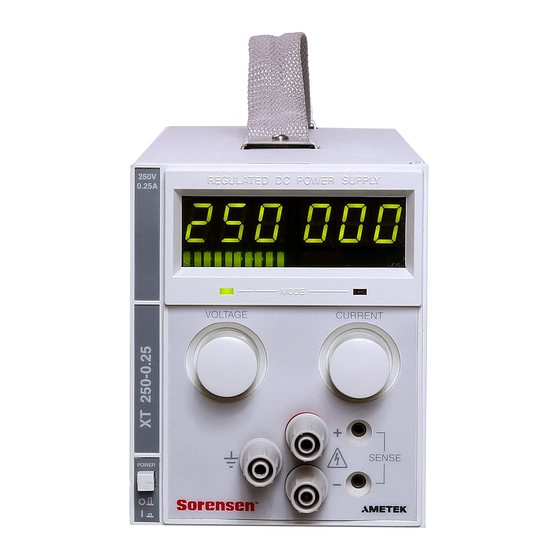
Features and Specifications Front Panel Controls Front Panel Controls Figure 1.1 to review the controls, LEDs, and meters located on the unit’s front panel. Digital Display of DC Output Remote Programming LED (PGM) (Volts, Amperes) REGULATED DC POWER SUPPLY (For units with APG installed. See also Figure 1.2). -
Page 16: Rear Panel Connectors And Outputs
Features and Specifications Rear Panel Connectors and Outputs Remote Programming LED (REM) Shutdown LED (SRQ) OVP Adjust Potentiometer (OVP ADJ) OVP Shutdown (OVP) Figure 1.2 Remote Programming Interface Indicators (For units with a digital programming interface installed.) Rear Panel Connectors and Outputs Figure 1.3 for the connectors and outputs available at the rear panel. -
Page 17: Electrical Specifications
Features and Specifications Electrical Specifications Electrical Specifications Specifications are warranted over a temperature range of 0 to 30 °C with default local sensing. Above 30 °C, derate output linearly to zero at 70 °C. Specifications are subject to change without notice. Table 1.2 Electrical Specifications for 7.5 V to 30 V Models Models 15-4... - Page 18 Features and Specifications Electrical Specifications Table 1.3 Electrical Specifications for 60 V to 250 V Models Models 60-1 120-0.5 250-0.25 Output Ratings: Output Voltage 0-60 V 0-120 V 0-250 V Output Current 0-1 A 0-0.5 A 0-0.25 A Output Power 60 W 60 W 60 W...
-
Page 19: Additional Electrical Specifications
Features and Specifications Additional Electrical Specifications Additional Electrical Specifications <100 μs recovery to 0.05% band, for ± 50% Voltage Mode Transient Response Time load change in the range of 25% to 100% of the rated load. Time delay from power on until 1.5 s maximum output stable Output Noise and Ripple... -
Page 20: Environmental Specifications
Features and Specifications Environmental Specifications Maximum Remote Sense Line 0.5 V/line Drop Compensation. (Line drop must be deducted from the supply’s maximum output voltage.) Environmental Specifications Operating Ambient Temperature 0 to 30 °C with default local sensing. Above 30 °C, derate output linearly to 0 at 70 °C. Storage Temperature Range –55°... -
Page 21: Chassis Dimensions And Weight
Features and Specifications Chassis Dimensions and Weight Approvals (up to 120 Vdc output) CSA certified to CSA C22.2 No. 107.1 FCC Part 15B and Industry Canada Class A CE Marked for Low Voltage Directive and EMC Directive (Class A emissions) Chassis Dimensions and Weight Single Output Unit... - Page 22 Features and Specifications Chassis Dimensions and Weight Operating Manual for XT Series Power Supply...
-
Page 23: Introduction
Section 2. Installation Introduction This section provides recommendations and procedures for inspecting, installing, and testing the power supply. Basic Setup Procedure Table 2.1 Basic Setup Procedure Step# Description Action Reference “Initial Inspection” on page 21 Inspection Perform an initial physical inspection of the supply. -
Page 24: Rack Mounting
Installation Rack Mounting Rack Mounting Use the power supply in benchtop or in rack-mounted applications. WARNING Ensure that any mounting screws do not protrude more than 1/8 in. (3.0 mm) into the bottom of the unit. The power is supply is designed to fill 1/4 of a standard 19 in (483 mm) equipment rack. -
Page 25: Ac Input Cord
Installation Functional Tests Table 2.2 Operational AC Input Voltage Ranges and Frequency AC Voltage Range Frequency φ (standard) 104-127 Vac 1 57-63 Hz φ (AC220 / AC230 / AC240 options) 200-250 Vac 1 110 Vac (option M1) 47-63 Hz 115-230 Vac switching unit (option M43) AC Input Cord WARNING... -
Page 26: Current Mode Operation Check
Installation Functional Tests Voltage Mode 1. Ensure that the front panel voltage and current control are turned fully Operation counter-clockwise. Check 2. Set the power switch to ON. 3. Rotate the current control one half-turn clockwise. Slowly rotate the voltage control clockwise and observe the digital meter. -
Page 27: Introduction
Section 3. Load Connection and Sensing Introduction This section covers single and multiple load connection, constant voltage and constant current operating modes, and alternate power supply configurations such as series and parallel connections. Load Connection WARNING There is a potential shock hazard at the load when using a power supply with an output greater than 40 V. -
Page 28: Load Wiring
Load Connection and Sensing Load Connection Load Wiring To select wiring for connecting the load to the power supply, consider the following factors: • insulation rating of the wire • current carrying capacity of the wire • maximum load wiring length for operation with sense lines •... - Page 29 Load Connection and Sensing Load Connection Load Wiring Length for Operation with Sense Lines For applications using remote sensing, you must limit the voltage drop across each load line. See Figure 3.1 for some maximum allowable lengths for a given load current and wire size. We recommend that you use the larger load wiring to ensure a smaller voltage drop (0.1 V typical maximum), although units can compensate for up to 0.5 V drop in each line...
-
Page 30: Connecting Multiple Loads
Load Connection and Sensing Grounding Rear Panel Terminals To make load connections, attach the wire using the steps below: 1. Strip load wires 0.25 in.(6 mm) 2. Using a flat-bladed 1/8 in. (3 mm) screwdriver, loosen the positive (+) and negative (−) output terminal screws on the output terminal block. -
Page 31: Local Sensing
Load Connection and Sensing Local Sensing Local Sensing Sensing of the output voltage is available from both the rear panel and the front panel output connectors. Default local sensing regulates the voltage at the power supply output terminal. Use remote sensing (see “Remote Sensing” on page 32) when the voltage needs to be regulated at the load rather than at the power supply output terminals. -
Page 32: Remote Sensing
Load Connection and Sensing Remote Sensing Remote Sensing WARNING There is a potential shock hazard at the sense points when using a power supply with a rated output greater than 40 V. Ensure that connections at the load end are shielded to prevent contact with hazardous voltages. -
Page 33: Introduction
Section 4. Operation Introduction Once you have installed the power supply and have connected both the AC input power and the load as covered in Section 2 Installation, the power supply is ready to operate. • Operating Modes, below, offers a brief explanation of Constant Voltage and Constant Current Mode operation. -
Page 34: Operation Operating Modes
Operation Operating Modes Note The control circuits have been designed to allow you to set output voltage and current up to 5% over the model-rated maximum values. The power supply will operate within these extended ranges, but we cannot guarantee full performance to specification. -
Page 35: Automatic Mode Crossover
Operation Using Multiple Supplies Automatic The automatic crossover system allows the power supply to automatically switch Mode operating modes in response to changing load requirements. For example, if the load current attempts to increase above the setting of the current adjust control, the unit Crossover will switch automatically from CV to CI mode. - Page 36 Operation Using Multiple Supplies Note You do not need to use remote sensing for series operation. If you choose to use it, “Remote Sensing” on page 32 refer to Diodes CR1 and CR2 protect sense circuits during transient events such as momentary current limit events which may cause supply outputs to collapse.
-
Page 37: Split Supply Operation
Operation Using Multiple Supplies Split Supply Split supply operation uses two power supplies to obtain two positive voltages with Operation a common ground, or to obtain a positive-negative supply. Two Positive Voltages To obtain two positive voltages, connect the negative output terminals of both supplies together in a common connection. - Page 38 Operation Using Multiple Supplies Figure 4.5 Split Supply Operation of Multiple Supplies (Positive-negative supply) Note The optional Analog Programming (APG) Interface has a Master/Slave Tracking feature which will allow one-knob control of both supplies in a split supply configuration. Operating Manual for XT Series Power Supply...
Need help?
Do you have a question about the Sorensen XT Series and is the answer not in the manual?
Questions and answers