
Related Manuals for Ametek Sorensen SGA Series DC


Summary of Contents for Ametek Sorensen SGA Series DC
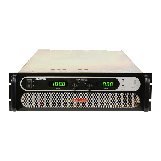
- Page 1 SGA Series DC Power Supplies Operation Manual M550129-01 Rev AF www.programmablepower.com...
-
Page 3: Contact Information
AMETEK Programmable Power, Inc., division of AMETEK, Inc), is a global leader in the design and manufacture of precision, programmable power supplies for R&D, test and measurement, process control, power bus simulation and power conditioning applications across diverse industrial segments. From bench-top supplies to... - Page 4 AMETEK will, at its expense, deliver the repaired or replaced Product or parts to the Buyer. Any warranty of AMETEK will not apply if the Buyer is in default under the Purchase Order Agreement or where the Product or any part thereof: ...
-
Page 5: Important Safety Instructions
Use safety glasses during open cover checks to avoid personal injury by any sudden component failure. Neither AMETEK Programmable Power Inc., San Diego, California, USA, nor any of the subsidiary sales organizations can accept any responsibility for personnel, material or inconsequential injury, loss or damage that results from improper use of the equipment and accessories. -
Page 6: Safety Symbols
SAFETY SYMBOLS WARNING: Electrical Shock Hazard HAZARD: Strong oxidizer GENERAL WARNING/CAUTION: Read the accompanying message for specific information. BURN HAZARD: Hot Surface Warning. Allow to cool before servicing. DO NOT TOUCH: Touching some parts of the instrument without protection or proper tools could result in damage to the part(s) and/or the instrument. -
Page 7: Fcc Notice
FCC NOTICE This equipment has been tested and found to comply with the limits for a Class A digital device, pursuant to part 15 of the FCC Rules. These limits are designed to provide reasonable protection against harmful interference when the equipment is operated in a commercial environment. - Page 8 ABOUT THIS MANUAL AND REGULATORY COMPLIANCE This manual has been written for the Sorensen SGA Series of power supplies, which have been designed and certified to meet the Low Voltage and Electromagnetic Compatibility Directive Requirements of the European Community. These models have been designed and tested to meet the Electromagnetic Compatibility directive (European Council directive 2004/108/EC;...
-
Page 9: Table Of Contents
CONTENTS SECTION 1 OVERVIEW .......... 1-1 General Description ....................1-1 Specifications ......................1-3 1.2.1 Environmental Characteristics .................. 1-3 1.2.2 Electrical Characteristics ................... 1-3 1.2.3 SGA Series Voltage and Current Specifications ............1-7 1.2.4 Physical Characteristics .................... 1-8 SECTION 2 INSTALLATION ........2-1 Inspection ....................... - Page 10 Contents Sorensen SGA Series 3.3.4 Overvoltage Protection ...................3-13 Remote Analog Control Connector (J1) .............. 3-14 Remote Current Programming ................3-18 3.5.1 Remote Current Programming by Resistance ............3-18 3.5.2 Remote Current Programming by Voltage Source ..........3-19 Remote Voltage Programming ................3-20 3.6.1 Remote Voltage Programming by Resistance ............3-20 3.6.2...
-
Page 11: List Of Tables
Sorensen SGA Series Contents LIST OF TABLES Table 2–1. Maximum AC Current Ratings, PFC Models ..........2-9 Table 2–2. Maximum AC Current Ratings, Non-PFC Models ........2-9 Table 2–3. Input/Output Connectors ................2-9 Table 2–4. Input Terminal Connections ..............2-10 Table 2–5. - Page 12 Contents Sorensen SGA Series Figure 3-2. Rear Panel Interface, Standard, 3U Models 10V-30V ....... 3-3 Figure 3-3. Rear Panel Interface, GPIB Option, 3U Models 10V-30V ......3-3 Figure 3-4. Rear Panel Interface, Ethernet Option, 3U Models 10V-30V ..... 3-3 Figure 3-5. Rear Panel Interface, Standard, 3U Models 40V-600V ......3-4 Figure 3-6.
-
Page 13: Section 1 Overview
SECTION 1 OVERVIEW GENERAL DESCRIPTION The Sorensen SGA Series are general purpose power supplies designed specifically for laboratory test and systems applications requiring programmable DC sources with good performance characteristics, such as accuracy, regulation, and ripple/noise. These power supplies are constant- current/constant-voltage supplies with an automatic crossover feature. -
Page 14: Figure 1-1. Model Number Decoding
Overview Sorensen SGA Series SG A 100 X 100 C - 1A AA AJ Control Designation Modifications A = Analog I = Intelligent Process Options Voltage 4-15 kW = "X" Remote Control Options 20-30 kW = "/" Input Voltage Options Current For units up to 999 V/999 A, voltage and current are represented in numeric format, e.g., “100”... -
Page 15: Specifications
Sorensen SGA Series Overview SPECIFICATIONS The following subsections provide environmental, electrical, and physical characteristics for the SGA Series power supplies. Note: Specifications are subject to change without notice. Note: The SGA Series power supplies are intended for indoor use only. Refer to Section 2.3 for use/location requirements. - Page 16 Overview Sorensen SGA Series Parameter Specification Power Factor (at full rated load; 50/60 Hz); contact factory for power factor of specific models PFC models: 10V-30V, 50V, 0.90, typical, for all AC input ratings; with passive power factor 1000V, and models with optional correction (PFC) modification, “PF”...
- Page 17 Sorensen SGA Series Overview Parameter Specification Output Voltage Fall Time 10 ms, maximum, from 90-10% of programming change from rated output voltage to zero for 10V-30V models; (with rated load, resistive; current fall contact factory for values of specific models time same) 50 ms, maximum, from 90-10% of programming change from rated output voltage to zero for 10V-30V models;...
- Page 18 Overview Sorensen SGA Series Parameter Specification Resistive-Control Programming Voltage 0–5 k for 0-100% of rated output voltage Current 0–5 k for 0-100% of rated output current Voltage-Control Programming Voltage 0–5 VDC or 0–10 VDC for 0-100% of rated output voltage Current 0–5 VDC or 0–10 VDC for 0-100% of rated output current Overvoltage Protection (OVP)
-
Page 19: Sga Series Voltage And Current Specifications
Sorensen SGA Series Overview 1.2.3 SGA SERIES VOLTAGE AND CURRENT SPECIFICATIONS The following tables present the specifications for rated voltage and current, and ripple/noise for the 10V-1000V models. Ripple/ Ripple/ Rated Current, ADC Rated Noise** Noise* Voltage, RMS, PK–PK, 4 kW 5 kW 8 kW 10 kW... -
Page 20: Physical Characteristics
Overview Sorensen SGA Series 1.2.4 PHYSICAL CHARACTERISTICS 3U Models, 3U Models, 6U Models, Dimensions 10V-30V 40V-1000V 60V-600V Width 19.00 in (48.26 cm) 19.00 in (48.26 cm) 19.00 in (48.26 cm) From inner surface of front panel to maximum protrusion of protective covers at rear panel;... -
Page 21: Section 2 Installation
Minimum items included in the ship kit: AMETEK manuals CD-ROM (P/N M550008-01) containing the SGA Series DC Power Supplies Operation Manual (this manual, P/N M550129-01) and the SG manual for the digital interface options, IEEE 488.2/RS232 and Ethernet Programming Manual (P/N M550129-03). -
Page 22: Location And Mounting
Installation Sorensen SGA Series Hardware for input/output terminal power connections: 3U, 4-15 kW, 10V-30V models: 1/2-13UNC-2B x 1.25" long, 4 ea, with nut, washer, and lockwasher; 3U, 5-15 kW, 40V-600V models: 3/8-16UNC-2B x 1.0”, 2 ea, with nut, washer, and lockwasher; 3U, 5-15 kW, 800V and 1000V models have studs, -20UNC-2B, 2 ea, with nut, washer, and lockwasher installed on rear panel;... -
Page 23: Rack Mounting
Support the SGA Series unit using appropriate L-brackets or rack mount slides; suggested slide kits are listed as follows: Rack Mount Slide Kit (Option): 3U models, 4–15 kW: AMETEK part number K550212-01 6U models, 20–30 kW: AMETEK part number K550213-01 M550129-01 Rev AF... -
Page 24: K550212-01 Assembly Steps (Option Kit For 3U Models)
Installation Sorensen SGA Series 2.3.2 K550212-01 ASSEMBLY STEPS (OPTION KIT FOR 3U MODELS) Figure 2-1. Rack Mount Assembly for 3U Models M550129-01 Rev AF... - Page 25 Sorensen SGA Series Installation WARNING! A minimum two-person lift is required for the 3U SGA Series power supply, which weighs up to 110 lb (50 kg) depending on the model. Refer to Figure 2-1 for 3U rack mount assembly drawing for the following instructions: 1.
-
Page 26: K550213-01 Assembly Steps (Option Kit For 6U Models)
Installation Sorensen SGA Series 2.3.3 K550213-01 ASSEMBLY STEPS (OPTION KIT FOR 6U MODELS) Figure 2-2. Rack Mount Assembly for 6U Models M550129-01 Rev AF... -
Page 27: Chassis Removal From Rack
Sorensen SGA Series Installation WARNING! A minimum three-person lift is required for the 6U SGA Series power supply, which weighs up to 170 lb (77kg) depending on the model. Refer to Figure 2-2 for 6U rack mount assembly drawing for the following instructions: 1. -
Page 28: Input/Output Connections
Installation Sorensen SGA Series INPUT/OUTPUT CONNECTIONS Refer to Table 2–1 for AC input current requirements and Section 1.2.3 for output current specifications. Table 2–3 provides information on the external input and output connections for the SGA Series models. Table 2–4 provides input connections descriptions, and Table 2–5 provides output connection descriptions. -
Page 29: Table 2-1. Maximum Ac Current Ratings, Pfc Models
Sorensen SGA Series Installation Model Ratings Input Line Current, A(RMS) AC Input Input Voltage Option Voltage, 5 kW 10 kW 15 kW 20 kW 25 kW 30 kW Model Code 208/230 40V-1000V 380/400 440/480 4 kW 8 kW 12 kW 5 kW 10 kW 15 kW 208/230 10V-15V... -
Page 30: Table 2-4. Input Terminal Connections
Installation Sorensen SGA Series Power Supply Type Connection Connection Description Feed-Through terminal block with 4 kW to 15 kW, 3U AC Input compression terminals AC Input 20 kW to 30 kW, 6U Bus Bar with holes for 1/4–20 bolts All 3U and 6U Chassis Safety Ground 1/4-20 stud Table 2–4. -
Page 31: Wire Selection
Sorensen SGA Series Installation WIRE SELECTION Care must be taken to properly size all conductors for the input and output of the power supply. This section provides guidance in the selection of wire size. CAUTION! Cables with Class B or C stranding should be used. Fine-stranded (flexible) cables should not be used unless crimp-on lugs or ferrules are used that are approved for fine-stranded cables. - Page 32 Installation Sorensen SGA Series When determining the optimum cable specification for your power applications, the same engineering rules apply whether at input or output of an electrical device. Thus, this guide applies equally to the AC input cable and DC output cable for this power supply and application loads. Power cables must be able to safely carry maximum load current without overheating or causing insulation degradation.
-
Page 33: Table 2-9. Wire Resistance And Voltage Drop, 20°C
Sorensen SGA Series Installation Column 1 Column 2 Column 3 Column 4 Ohms/100 Ft Voltage Drop/100 Ft Size, AWG A(RMS) (One Way) (Column 2 x Column 3) 0.253 5.06 0.156 3.90 0.999 3.00 0.063 2.52 0.040 2.20 0.025 1.75 0.020 1.70 0.016 1.52... -
Page 34: Load Considerations
Installation Sorensen SGA Series LOAD CONSIDERATIONS This section provides guidelines for incorporating protective diode networks at the output of the power supply to prevent damage while driving inductive loads or loads having stored energy that could be circulated back to the power supply. -
Page 35: Outline And Installation Drawings
Sorensen SGA Series Installation OUTLINE AND INSTALLATION DRAWINGS Figure 2-4 through Figure 2-7 show the outlines and overall dimensions for installation of the 3U and 6U models of the SGA Series power supplies. Figure 2-8 through Figure 2-16 show locations of rear panel connectors. Figure 2-17 shows protective covers for the AC input and DC output of the 3U 10V-30V models. -
Page 36: Figure 2-4. Installation Drawing, 3U Models 10V-30V
Installation Sorensen SGA Series Figure 2-4. Installation Drawing, 3U Models 10V-30V 2-16 M550129-01 Rev AF... -
Page 37: Figure 2-5. Installation Drawing, 3U Models 40V-600V
Sorensen SGA Series Installation Figure 2-5. Installation Drawing, 3U Models 40V-600V M550129-01 Rev AF 2-17... -
Page 38: Figure 2-6. Installation Drawing, 3U Models 800V-1000V
Installation Sorensen SGA Series Figure 2-6. Installation Drawing, 3U Models 800V-1000V 2-18 M550129-01 Rev AF... -
Page 39: Figure 2-7. Installation Drawing, 6U Models 20 Kw To 30 Kw
Sorensen SGA Series Installation Figure 2-7. Installation Drawing, 6U Models 20 kW to 30 kW M550129-01 Rev AF 2-19... -
Page 40: Figure 2-8. Rear Panel, Standard,3U Models 10V-30V
Installation Sorensen SGA Series Figure 2-8. Rear Panel, Standard,3U Models 10V-30V 2-20 M550129-01 Rev AF... -
Page 41: Figure 2-9. Rear Panel, Gpib Option, 3U Models 10V-30V
Sorensen SGA Series Installation Figure 2-9. Rear Panel, GPIB Option, 3U Models 10V-30V M550129-01 Rev AF 2-21... -
Page 42: Figure 2-10. Rear Panel, Ethernet Option, 3U Models 10V-30V
Installation Sorensen SGA Series Figure 2-10. Rear Panel, Ethernet Option, 3U Models 10V-30V 2-22 M550129-01 Rev AF... -
Page 43: Figure 2-11. Rear Panel, Standard, 3U Models 40V-600V
Sorensen SGA Series Installation Figure 2-11. Rear Panel, Standard, 3U Models 40V-600V M550129-01 Rev AF 2-23... -
Page 44: Figure 2-12. Rear Panel, Gpib Option, 3U Models 40V-600V
Installation Sorensen SGA Series Figure 2-12. Rear Panel, GPIB Option, 3U Models 40V-600V 2-24 M550129-01 Rev AF... -
Page 45: Figure 2-13. Rear Panel, Ethernet Option, 3U Models 800V And 1000V
Sorensen SGA Series Installation Figure 2-13. Rear Panel, Ethernet Option, 3U Models 800V and 1000V M550129-01 Rev AF 2-25... -
Page 46: Figure 2-14. Rear Panel, Standard, 6U Models 20Kw-30Kw
Installation Sorensen SGA Series Figure 2-14. Rear Panel, Standard, 6U Models 20kW-30kW 2-26 M550129-01 Rev AF... -
Page 47: Figure 2-15. Rear Panel, Gpib Option, 6U Models 20Kw-30Kw
Sorensen SGA Series Installation Figure 2-15. Rear Panel, GPIB Option, 6U Models 20kW-30kW M550129-01 Rev AF 2-27... -
Page 48: Figure 2-16. Rear Panel, Ethernet Option, 6U Models 20Kw-30Kw
Installation Sorensen SGA Series Figure 2-16. Rear Panel, Ethernet Option, 6U Models 20kW-30kW 2-28 M550129-01 Rev AF... -
Page 49: Figure 2-17. Instructions For Assembly Of Ac And Dc Covers
Sorensen SGA Series Installation Figure 2-17. Instructions for Assembly of AC and DC Covers M550129-01 Rev AF 2-29... - Page 50 Installation Sorensen SGA Series This page intentionally left blank. 2-30 M550129-01 Rev AF...
-
Page 51: Section 3 Operation
SECTION 3 OPERATION INTRODUCTION The SGA series provides simplicity and ease of use through analog front panel potentiometer controls. LED meters display bright, easy-to-read voltage and current output measurements. This section provides detailed information on the controls and indicators, and the operation of the SGA Series. -
Page 52: Table 3-1. Front Panel Controls And Indicators
Operation Sorensen SGA Series WARNING! The power-up factory default state is output enabled, where the output will be energized at the settings of voltage and current Item Reference Functional Description Two–position switch turns the power supply on and off. WARNING! ON/OFF Switch OFF position does not remove AC input from internal circuits or input... - Page 53 Sorensen SGA Series Operation Figure 3-2. Rear Panel Interface, Standard, 3U Models 10V-30V Figure 3-3. Rear Panel Interface, GPIB Option, 3U Models 10V-30V Figure 3-4. Rear Panel Interface, Ethernet Option, 3U Models 10V-30V M550129-01 Rev AF...
- Page 54 Operation Sorensen SGA Series Figure 3-5. Rear Panel Interface, Standard, 3U Models 40V-600V Figure 3-6. Rear Panel Interface, GPIB Option, 3U Models 40V-600V Figure 3-7. Rear Panel Interface, Ethernet Option, 3U Models 800V and 1000V M550129-01 Rev AF...
- Page 55 Sorensen SGA Series Operation Figure 3-8. Rear Panel Interface, Standard, 6U Models 20kW-30kW Figure 3-9. Rear Panel Interface, GPIB Option, 6U Models 20kW-30kW Figure 3-10. Rear Panel Interface, Ethernet Option, 6U Models 20kW-30kW M550129-01 Rev AF...
-
Page 56: Table 3-2. Rear Panel Connectors And Controls, Standard
Operation Sorensen SGA Series Item Reference Functional Description AC Input Connectors Connection for 3-phase AC. Connection for safety ground wire. AC Input Safety Ground DC Output Bus Bars Positive (+) and negative (–) outputs. Positive (+) and negative (–) outputs for 800V and HV DC Output Studs 1000V models only. -
Page 57: Table 3-3. Rear Panel Connectors And Controls, Gpib Option
Sorensen SGA Series Operation Item Reference Functional Description AC Input Connectors Connection for 3-phase AC. Connection for safety ground wire. AC Input Safety Ground DC Output Bus Bars Positive (+) and negative (–) outputs. Positive (+) and negative (–) outputs for 800V and HV DC Output Studs 1000V models only. -
Page 58: Table 3-4. Rear Panel Connectors And Controls, Ethernet Option
Operation Sorensen SGA Series Item Reference Functional Description AC Input Connectors Connection for 3-phase AC. Connection for safety ground wire. AC Input Safety Ground DC Output Bus Bars Positive (+) and negative (–) outputs. Positive (+) and negative (–) outputs for 800V and HV DC Output Studs 1000V models only. -
Page 59: Shaft Lock (Option)
Sorensen SGA Series Operation SHAFT LOCK (OPTION) This option replaces the standard control knobs with a two-piece shaft lock. These are installed over the voltage and current adjustment potentiometer shafts to prevent rotating under conditions of shock, vibration, or accidental contact. -
Page 60: Front Panel Operation
Operation Sorensen SGA Series FRONT PANEL OPERATION The SGA Series power supply is shipped from the factory configured for front panel voltage/current/OVP control, and with the remote sense not connected (default to internal voltage sensing at chassis output terminals). The remote sense leads must be connected externally by the user to achieved performance specifications. -
Page 61: Constant-Voltage Mode Operation
Sorensen SGA Series Operation 3.3.2 CONSTANT-VOLTAGE MODE OPERATION When the power supply is in the Constant-Voltage mode, it functions as a voltage source, and the output voltage of the supply is controlled by the Voltage knob on the front panel or by the remote analog voltage programming input;... -
Page 62: Constant-Current Mode Operation
Operation Sorensen SGA Series 3.3.3 CONSTANT-CURRENT MODE OPERATION When the power supply is in the Constant-Current Mode, it functions as a current source, and the output current of the supply is controlled by the Current knob on the front panel or by the remote analog current programming input;... -
Page 63: Overvoltage Protection
Sorensen SGA Series Operation 3.3.4 OVERVOLTAGE PROTECTION The Overvoltage Protection (OVP) function allows the supply to shutdown the output, if it were to exceed a preset voltage. This may be used to protect sensitive circuits or loads from damage caused by an excessive voltage on the output of the supply. -
Page 64: Remote Analog Control Connector (J1)
Operation Sorensen SGA Series 13. If OVP mode did not function as indicated above, verify your setup and perform the check again. If the function continues to fail, contact the factory for assistance. REMOTE ANALOG CONTROL CONNECTOR (J1) The Analog Control connector (J1) of the Remote Analog Interface on the rear panel allows the unit to be configured for different operating configurations: front panel and remote current programming, front panel and remote voltage programming, output current and voltage monitoring, output... - Page 65 Sorensen SGA Series Operation Figure 3-12. Analog Control Connector (J1) Pin-Out Electrical Pin Reference Functional Description Parameters Isolated remote control input for output on/off with an applied Zin ~ 6 k in AC/DC voltage source. A positive (+) 6-120 VDC or an AC series with anode input of 12- 240 VAC will enable (turn-on) the output of the ON/OFF...
- Page 66 Operation Sorensen SGA Series Electrical Pin Reference Functional Description Parameters Pin J1-20 (VP RTN). Circuit is electrically connected to the output power negative terminal. See Section 3.6. Remote control input for current programming using a voltage source: 0-5 VDC = 0-100% of full-scale output current. Do not IP 5V exceed an input of 13.3 VDC.
-
Page 67: Table 3-5. Analog Control Connector (J1), Designations And Functions
Sorensen SGA Series Operation Electrical Pin Reference Functional Description Parameters Voltage programming signal return to be used with Pins J1-9, J1-15 or J1-21; also must be externally connected to Pin J1-6 VP RTN Zin ~ 10 k (COM) signal return when voltage programming is utilized. Circuit is electrically connected to the output power negative terminal. -
Page 68: Remote Current Programming
Operation Sorensen SGA Series REMOTE CURRENT PROGRAMMING Remote current programming is used for applications that require the output current to be programmed (controlled) from a remote instrument. An external resistance or external voltage source may be used as a programming device. When using remote current programming, a shielded, twisted-pair cable is recommended to prevent noise interference to programming signals. -
Page 69: Remote Current Programming By Voltage Source
Sorensen SGA Series Operation 3.5.2 REMOTE CURRENT PROGRAMMING BY VOLTAGE SOURCE Two inputs are provided for remote voltage-programming of the output current: 5 VDC full-scale and 10 VDC full-scale. The DC voltage source is connected between Pin J1-10 (IP 5V) for 5 VDC source, or Pin J1-16 (IP 10V) for 10 VDC source, and the return Pin J1-23 (IP RTN). -
Page 70: Remote Voltage Programming
Operation Sorensen SGA Series REMOTE VOLTAGE PROGRAMMING Remote voltage programming configuration is used for applications that require the output voltage to be programmed (controlled) from a remote source. An external resistance or external voltage source may be used as a programming device. -
Page 71: Remote Voltage Programming By Voltage Source
Sorensen SGA Series Operation 3.6.2 REMOTE VOLTAGE PROGRAMMING BY VOLTAGE SOURCE Two inputs are provided for remote voltage-programming of the output voltage: 5 VDC full-scale and 10 VDC full-scale. The DC voltage source is connected between Pin J1-9 (VP 5 V) for 5 VDC source, or Pin J1-15 (VP 10V) for 10 VDC source, and the return Pin J1-20 (VP RTN). -
Page 72: Remote Overvoltage Protection Programming
Operation Sorensen SGA Series REMOTE OVERVOLTAGE PROTECTION PROGRAMMING CAUTION! Do not program the remote overvoltage setpoint greater than 10% above the power supply rated voltage (5.5 VDC programming voltage source), as internal power supply damage might occur (except as noted for reset). -
Page 73: Remote Output On/Off Control
Sorensen SGA Series Operation REMOTE OUTPUT ON/OFF CONTROL Remote output on/off control may be accomplished by contact closure, or through an opto-isolated interface with external voltage sources, AC/DC or TTL/CMOS. 3.8.1 REMOTE OUTPUT ON/OFF BY CONTACT CLOSURE Application of a contact closure between Pins J1-5 and J1-6 will enable the output. -
Page 74: Remote Shutdown (S/D)
Operation Sorensen SGA Series 14 ISO TTL/CMOS ISO RTN 2 Figure 3-20. Remote Output ON/OFF Using Isolated TTL/CMOS Source 3.8.3 REMOTE SHUTDOWN (S/D) A remote +12 VDC voltage can be connected externally between Pin J1-18 (S/D Fault) and Pin J1-24 (COM) to disable, i.e., shut down the output of the power supply;... -
Page 75: Remote Sensing
Sorensen SGA Series Operation REMOTE SENSING Remote voltage sensing is recommended at all times, whether the sense leads are connected to the load or to the output terminals. Remote sensing is required to meet the performance specifications of the power supply. It is essential in applications where the load is located some distance from the power supply, or the voltage drop of the power output leads significantly interferes with load regulation. - Page 76 Operation Sorensen SGA Series CAUTION! If the power supply is operated with load power lines disconnected and remote sense lines connected, internal power supply damage might occur, since output load current could flow through the remote sense terminals. To use remote voltage sensing, connect the power supply as described in Figure 3-23 for the 10V-800V models, and in Figure 3-24 for the 1000V model.
- Page 77 Sorensen SGA Series Operation Load J3-1: Sense (+) J3-2: Not Used J3-3: Not Used J3-4: Sense (-) Power Supply Output Figure 3-24. Remote Sense Connection at the Load, 1000V Model M550129-01 Rev AF 3-27...
-
Page 78: Floating And Polarized Output
Operation Sorensen SGA Series FLOATING AND POLARIZED OUTPUT 3.10 The SGA Series supply can be set up for a Positive or Negative supply, as well as standard operation as a floating output supply. LOATING UTPUT The output terminals are normally floating from chassis ground. No extra steps or connections are required for a floating output. -
Page 79: Parallel And Series Operation
Sorensen SGA Series Operation PARALLEL AND SERIES OPERATION 3.11 Parallel and series modes of operation are used for applications requiring more current or voltage than is available from a single power supply. To meet the requirements for greater output current or voltage, up to five supplies could be connected in parallel, or up to two supplies could be connected in series. - Page 80 Operation Sorensen SGA Series Figure 3-25. Parallel Connection and Remote Sense 3-30 M550129-01 Rev AF...
-
Page 81: Series Operation
Sorensen SGA Series Operation 3.11.2 SERIES OPERATION Series operation is used to obtain a higher aggregate output voltage using two units. Each supply is operated individually, and is set up as follows: Connect the negative terminal (–) of one supply to the positive terminal (+) of the next supply;... - Page 82 Operation Sorensen SGA Series This page intentionally left blank. 3-32 M550129-01 Rev AF...
-
Page 83: Section 4 Calibration And Verification
SECTION 4 CALIBRATION AND VERIFICATION INTRODUCTION This section provides calibration and verification procedures for the SGA Series power supplies and the Remote Isolated Analog Interface control (option). Refer to the SG Programming Manual for calibration of display readback and remote digital programming option. 4.1.1 CALIBRATION AND VERIFICATION CYCLE Annual calibration and verification is recommended. -
Page 84: Calibration And Verification Procedures
Installation Sorensen SGA Series sense leads, and ensure that the digital voltmeter that measures output voltage is connected across the sense leads. CALIBRATION AND VERIFICATION PROCEDURES WARNING! Hazardous voltages might be present on the output, even after it is disabled, due to stored capacitive charge. -
Page 85: Constant-Current Mode
Sorensen SGA Series Installation 4.2.1 CONSTANT-CURRENT MODE 1. Setup the SGA Series unit to operate with remote current programming using an external 0-5 VDC voltage-source, as shown in Figure 3-14 in Section 3.5.2. Ensure that Pins J1-5 and J1-6 are jumpered to enable the output. -
Page 86: Resistive-Control Programming Current Sources
Installation Sorensen SGA Series 4. Program the output current, with the front panel control or remote interface, to 100% of rated output current. 5. Apply AC power, turn the unit on, and press "Output On" button to enable the output (see Section 3.1.1). 6. -
Page 87: Remote Isolated Analog Interface (Option) Calibration And Verification Procedures
Sorensen SGA Series Installation 9. Apply AC power, turn the unit on, and press “Output On” button to enable the output (see Section 3.1.1). 10. Adjust R35 so that the measured output voltage equals 100% rated output voltage. 11. Turn off AC power, and remove all connections to the remote analog control connector (J1), except the jumper between Pins J1-5 and J1-6;... -
Page 88: Constant-Voltage Mode
Installation Sorensen SGA Series 8. Verify that the unit produces 100% 0.8% of rated output current. If necessary, adjust R33 for 100% of rated output current through the shunt. 9. Set the current programming source for 0.5 V 1 mV. - Page 89 Sorensen SGA Series Installation Standard Calibration Adjustments Isolated Analog (Option) R35 = VPRES (1 mA) Adjust Calibration Adjustments R33 = IPRES (1 mA) Adjust R39 = Full-Scale Voltage Adjust R74 = Full-Scale Voltage Adjust R35 = Zero Voltage Adjust R90 = Zero Voltage Adjust R33 = Full-Scale Current Adjust R69 = Full-Scale Current Adjust R47 = Zero Current Adjust...
- Page 90 Installation Sorensen SGA Series This page intentionally left blank. M550129-01 Rev AF...
-
Page 91: Section 5 Maintenance
SECTION 5 MAINTENANCE INTRODUCTION This chapter contains preventive maintenance information for the SGA Series power supplies. WARNING! All maintenance that requires removal of the cover of the unit should only be done by properly trained and qualified personnel. Hazardous voltages exist inside the unit. Disconnect the supply from the AC mains input before performing any maintenance. - Page 92 Maintenance Sorensen SGA Series No routine maintenance on the SGA Series is required, aside from periodic cleaning of the unit and inspection, as required by the environmental operating conditions: Once a unit is removed from service, vacuum all air vents, including the front panel grill.
-
Page 93: Fuses
Sorensen SGA Series Maintenance FUSES There are no user replaceable components in the power supply. Internal fuses are listed in Table 4.1. Fuses are sized for fault isolation, and, an open fuse might indicate that a circuit component has been damaged. Contact the factory for further assistance.. - Page 94 Maintenance Sorensen SGA Series This page intentionally left blank. M550129-01 Rev AF...
- Page 95 INDEX AC Input Connector, 3U, 2-10 Electrical Characteristics, 1-3 Screw Torque, 2-10 Environmental Characteristics, 1-3 Agency Approvals, 1-3 Analog Control Connector (J1), 3-14 Designations and Functions, 3-17 Flexible Cables, 2-11 Isolated Analog Voltage, 3-14 Floating Negative Terminal, 2-8 Return Connection, 3-14 Front Panel Drawing, 3-1 Fuses, 5-3 Calibration and Verification...
- Page 96 Index Sorensen SGA Series Ventilation, 2-2 Rear Panel Drawings, 2-15 Remote Current Programming, 3-18 Resistance Control, 3-18 Voltage Source Control, 3-19 Maintenance, 5-1 Remote Isolated Analog Interface Control, Cleaning/Inspection, 5-2 3-14 Fuses, 5-3 Remote Output On/Off Control, 3-23 Preventive, 5-1 Contact Closure Control, 3-23 Maximum AC Current Ratings, 2-9 External Source Control, 3-23...
- Page 97 This page intentionally left blank. M550129-01 Rev AF Index 3...
Need help?
Do you have a question about the Sorensen SGA Series DC and is the answer not in the manual?
Questions and answers