
Related Manuals for HP PROCURVE 6208M-SX


Summary of Contents for HP PROCURVE 6208M-SX
- Page 1 9304m, 9308m, and 6308m-sx and the hp procurve switch 6208m-sx (software release 6.6. x and 7.1. x) www.hp.com/go/hpprocurve...
- Page 2 Book 1: Installation and Getting Started Guide HP ProCurve Routing Switches for the 9304M, 9308M, 6308M-SX HP ProCurve Switch 6208M-SX and the (Software Releases 6.6.X and 7.1.X)
- Page 3 Hewlett-Packard. A copy of the specific warranty terms applicable to your HP product and replacement parts can be obtained from your HP Sales and Service Office or authorized dealer. Warranty See the Customer Support and Warranty booklet included with the product.
-
Page 4: Organization Of Product Documentation
These documents also are available in PDF file format on HP's ProCurve website. NOTE: In Book 2, most of the chapters apply only to the HP 9304M, HP 9308M, and HP 6308M-SX routing switches (and not the HP 6208M-SX switch). However, the QoS, ACL, STP, and VLAN chapters, and appendixes A and B apply to the HP 6208M-SX switch as well as the routing switches. -
Page 6: Safety And Emc Regulatory Statements
There are no user-serviceable parts inside these products. Any servicing, adjustment, maintenance, or repair must be performed only by service-trained personnel. These products do not have a power switch; they are powered on when the power cord is plugged in. Documentation reference symbol. If the product is marked with this symbol, refer to the product documentation to get more information about the product. -
Page 7: Informations Concernant La Sécurité
Installation and Getting Started Guide Informations concernant la sécurité WARNING CAUTION Cet appareil est un produit de classe I et possède une borne de mise à la terre. La source d'alimentation principale doit être munie d'une prise de terre de sécurité installée aux bornes du câblage d'entrée, sur le cordon d'alimentation ou le cordon de raccordement fourni avec le produit. -
Page 8: Onsiderazioni Sulla Sicurezza
Geräteingabeterminals, den Netzkabeln oder dem mit Strom belieferten Netzkabelsatz voraus. Sobald Grund zur Annahme besteht, daß der Schutz beeinträchtigt worden ist, das Netzkabel aus der Wandsteckdose herausziehen, bis die Erdung wiederhergestellt ist. Für LAN-Kabelerdung: • Wenn Ihr LAN ein Gebiet umfaßt, das von mehr als einem Stromverteilungssystem beliefert wird, müssen Sie sich vergewissern, daß... -
Page 9: Consideraciones Sobre Seguridad
Installation and Getting Started Guide Consideraciones sobre seguridad WARNING CAUTION Este aparato se enmarca dentro de la clase I de seguridad y se encuentra protegido por una borna de puesta a tierra. Es preciso que exista una puesta a tierra continua desde la toma de alimentación eléctrica hasta las bornas de los cables de entrada del aparato, el cable de alimentación o el juego de cable de alimentación suministrado. -
Page 10: Safety Information (Japan)
Safety and EMC Regulatory Statements Safety Information (Japan) -
Page 11: Safety Information (China)
Installation and Getting Started Guide Safety Information (China) Lasers The Gigabit-SX and Gigabit-LX Modules are Class 1 Laser Products. Laser Klasse 1 The modules comply with IEC 825-2: 1993... -
Page 12: Emc Regulatory Statements
Safety and EMC Regulatory Statements EMC Regulatory Statements U.S.A. FCC Class A This equipment has been tested and found to comply with the limits for a Class A digital device, pursuant to Part 15 of the FCC Rules. These limits are designed to provide reasonable protection against interference when the equipment is operated in a commercial environment. - Page 13 Installation and Getting Started Guide xii...
-
Page 14: Table Of Contents
EMC R AFETY AND EGULATORY AFETY NFORMATION ROUNDING ERVICING NFORMATIONS CONCERNANT LA SÉCURITÉ INWEISE ZUR ICHERHEIT ONSIDERAZIONI SULLA SICUREZZA ONSIDERACIONES SOBRE SEGURIDAD ) ... AFETY NFORMATION APAN ) ... AFETY NFORMATION HINA ASERS EMC R EGULATORY TATEMENTS U.S.A..ANADA USTRALIA EALAND APAN... - Page 15 ERMANENT DDRESS ...2-13 OUTING WITCHES ...2-14 WITCHES ...2-15 OUNTING THE EVICE ...2-15 ESKTOP NSTALLATION – C OUNT NSTALLATION – HP 6208M-SX OUNT NSTALLATION ONNECTING OWER TO THE EVICE ONNECTING ETWORK EVICES ...2-18 ONNECTORS ONNECTING TO THER WITCHES ONNECTING TO ORKSTATIONS...
- Page 16 ...3-24 ...3-25 TACACS/TACACS+ P OURCE FOR TATISTICS AND ONFIGURATION ...3-31 UTHORIZATION CCOUNTING ...3-34 ...3-34 RADIUS S TTRIBUTES ON THE ERVER HP D ...3-35 EVICE ...3-36 RADIUS ...3-36 ETHOD ISTS FOR ...3-38 ...3-38 RADIUS P OURCE FOR ...3-40 NFORMATION ...3-44 ETHOD...
- Page 17 HANGING THE LOCK IZE FOR ...6-3 PDATING OADING AND AVING ONFIGURATION ... 4-1 HELL ...4-2 ...4-2 ...4-2 LIENTS ...4-2 ESPONSE UTHENTICATION HP D ...4-3 EYS INTO THE EVICE ...4-4 ESPONSE UTHENTICATION ...4-4 ...4-5 UTHENTICATION ETRIES ...4-5 ...4-5 ...4-5 OGINS ...4-6 ...4-6...
- Page 18 EPLACING THE TARTUP ONFIGURATION WITH THE EPLACING THE UNNING ONFIGURATION WITH THE OGGING HANGES TO THE OPYING A ONFIGURATION AXIMUM IZES FOR TARTUP IAGNOSTIC RROR ODES AND AVING OR RASING MAGE AND CHEDULING A YSTEM ELOAD ELOADING AT A PECIFIC ELOADING AFTER A PECIFIC ISPLAYING THE...
- Page 19 ...7-17 ROTOCOL SSIST ...7-18 (VLAN ) ...7-18 ...7-19 ...7-19 UPPORT PER NTERFACE ) ...7-19 WITCH OUTING (BGP4) R ...7-21 OUTING ...7-21 ...7-22 ...7-22 ...7-23 ILTERS DVMRP) ...7-23 ...7-24 ELPER ...7-24 (VRRP) ...7-24 ROTOCOL (SRP) ...7-25 HP 6308M-SX ...8-5 OUTING WITCH...
- Page 20 ATES ...9-21 ...9-23 ...9-26 ...9-27 ONTROL ...9-28 EGOTIATION S) ...9-29 ...9-29 WITCHING ROUTING SWITCHES ONLY ...9-30 ...9-31 NTRIES ...9-32 ...9-34 (HP 6208M-SX RAFFIC EDUCTION ...9-51 ...9-55 ULTICAST ILTERS ...9-57 DDRESSES ...9-57 ROTOCOLS ARAMETER EFAULT ETTINGS ...9-61 ONITOR ORTS IRROR AND...
- Page 21 Installation and Getting Started Guide ARDWARE PECIFICATIONS ... A-1 LECTRICAL PECIFICATIONS ... A-1 HYSICAL PECIFICATIONS ... A-1 PERATING NVIRONMENT ... A-2 TORAGE NVIRONMENT ... A-2 LECTROMAGNETIC MISSIONS ... A-2 AFETY GENCY PPROVALS ... A-2 ASER OFTWARE PECIFICATIONS ... B-1 TANDARDS OMPLIANCE RFC S ...
-
Page 22: Getting Started
Introduction This guide describes how to install, configure, and monitor the following devices: • HP ProCurve Routing Switch 9308M • HP ProCurve Routing Switch 9304M • HP ProCurve Routing Switch 6308M-SX • HP ProCurve Switch 6208M-SX This guide also describes how to monitor these products using statistics and summary screens. -
Page 23: Terminology
A printed copy of this guide is included with your HP product. An electronic copy is also included as a PDF (Portable Document Format) file on the CD shipped with your HP product. -
Page 24: What's New In This Edition
Technical Support, then Software. • Support is as Close as the World Wide Web!—Included with your HP switch or routing switch, this document is a guide to HP support services and also provides information on your HP networking product warranty. - Page 25 Installation and Getting Started Guide • BGP4 re-advertises BGP routes even when OSPF or RIP routes to the same destination have a lower cost • Redistribution changes take place immediately • Option to redistribute Internal BGP (IBGP) routes into RIP and OSPF •...
-
Page 26: Support And Warranty Information
Option to suppress Telnet connection rejection message • Configurable block size for TFTP file transfers Support and Warranty Information Refer to Support is as Close as the World Wide Web, which was shipped with your HP switch or routing switch. Getting Started 1 - 5... - Page 27 Installation and Getting Started Guide 1 - 6...
-
Page 28: Installation
This information is required for managing the system using the Web management interface or using the CLI through Telnet. WARNING: Do not use the handles on the power supply units to lift or carry the HP 9304M or HP 9308M routing switch. -
Page 29: Installation Procedures
3. Chassis devices only – (Optional) Installing (or Removing) Redundant Power Supplies (page 2-6). The HP 9304M can hold one or two power supplies. The HP 9308M can hold up to four power supplies. If you have a power supply to install, it may be easier to install it before mounting the routing switch, although the power supplies are “hot swappable”, and can be installed or removed after the routing switch is... -
Page 30: Installation Precautions
WARNING: The HP 9304M chassis exceeds 40 lbs. (18 kg), or 47.7 lbs.(21.6 kg) when fully populated with modules and power supplies. Also, the HP 9308M chassis exceeds 55 lbs. (24.9 kg) or 69.1 lbs. (31.3 kg) when fully populated with modules and power supplies. TWO OR MORE PEOPLE ARE REQUIRED WHEN LIFTING, HANDLING, OR MOUNTING THESE ROUTING SWITCHES. -
Page 31: Preparing The Installation Site
NOTE: Modules for the HP 9308M slide in vertically with the module label (e.g. ProCurve 9300) and port number 1 at the top (Figure 2.3). Modules for the HP 9304M slide in horizontally with the module label (e.g. ProCurve 9300) and port number 1 on the left (Figure 2.4). -
Page 32: Removing Modules
CAUTION: If you remove a module and do not replace it, cover the slot opening with one of the blank plates you received with the routing switch to provide additional safety and airflow for the system. NOTE: Modules can be installed and removed when the unit is powered on (hot swap). There is no need to power the system down. -
Page 33: Installing (Or Removing) Redundant Power Supplies (Chassis Devices Only)
CAUTION: Power supplies are hot swappable but they should be disconnected from AC power before being installed or removed. That is, the routing switch can be running while a power supply is being installed or removed, but the power supply itself should not be connected to a power source. Otherwise, damage to the power supply or the routing switch could result. -
Page 34: Removing Power Supplies
CAUTION: Power supplies are hot swappable but they should be disconnected from AC power before being installed or removed. That is, the routing switch can be running while a power supply is being installed or removed, but the power supply itself should not be connected to a power source. Otherwise, damage to the power supply or the routing switch could result. -
Page 35: Verifying Proper Operation
4. Verifying Proper Operation After you have installed any modules or redundant power supplies, but before mounting the routing switch in its network location, you should first verify that it is working properly by plugging it into a power source and verifying that it passes its self test. -
Page 36: 5. Attaching A Pc Or Terminal
DB-9 or DB-25 connector, male or female. A console cable is provided with your switch or routing switch. Cable pin-outs and signalling for the serial cable are shown in Figure 2.5 and Figure 2.6. -
Page 37: Attaching A Pc Or Terminal Using A Direct Lan Connection
CAUTION: Before connecting Category 5 or better UTP copper networking cables to a chassis module on the HP 9304M or HP 9308M, use the CESD grounding tap (shipped with the HP 9304M and HP 9308M and with chassis modules designed for UTP copper networking cables). See the Cable Grounding Instructions included with the CESD grounding tap. - Page 38 Most PC serial ports also require a cable with a female DB-9 connector. Terminal connections will vary, requiring either a DB-9 or DB-25 connector, male or female. Serial cable options between an HP switch or routing switch and a PC terminal are shown in Figure 2.6.
-
Page 39: Assigning A Permanentp
Installation and Getting Started Guide 6. Assigning a Permanent Password CLI access does not require a password by default. If you want to configure a password, you must use the CLI. A password cannot be assigned through the Web management interface. The CLI contains the following access levels: •... -
Page 40: Assign A Permanent Ip Address
Terminal Using a Direct LAN Connection” on page 2-10.) On the HP 9304M or HP 9308M, you can configure up to 24 IP interfaces on each port, virtual interface, and loopback interface. On the HP 6308M-SX routing switch, you can increase this amount to up to 64 IP sub-net addresses per port by increasing the size of the subnet-per-interface table. -
Page 41: Switches
Switches Using a serial connection is the recommended method for assigning the IP address on a switch. (You also can use Telnet with a direct, terminal-to-device LAN connection if necessary—see “Attaching a PC or Terminal Using a Direct LAN Connection” on page 2-10.) To assign an IP Address to the HP 6208M-SX switch: 1. At the opening CLI prompt, enter enable. -
Page 42: Mounting The Device
WARNING: The HP 9304M chassis exceeds 40 lbs. (18 kg), or 47.7 lbs.(21.6 kg) when fully populated with modules and power supplies. Also, the HP 9308M chassis exceeds 55 lbs. (24.9 kg) or 69.1 lbs. (31.3 kg) when fully populated with modules and power supplies. TWO OR MORE PEOPLE ARE REQUIRED WHEN LIFTING, HANDLING, OR MOUNTING THESE ROUTING SWITCHES. - Page 43 Attach the device in the rack as illustrated in Step 3 of Figure 2.8. Proceed to “Connecting Power to the Device” below. Figure 2.8 Installing an HP 6208M-SX or HP 6308M-SX in a rack mount 2 - 16 Lin k...
-
Page 44: Installation
CAUTION: Before connecting Category 5 or better UTP copper networking cables to a chassis module on the HP 9304M or HP 9308M, use the CESD grounding tap (shipped with the HP 9304M and HP 9308M and with chassis modules designed for UTP copper networking cables). See the Cable Grounding Instructions included with the CESD grounding tap. -
Page 45: Connectors
Installation and Getting Started Guide Connectors • 10/100BaseTX ports come with RJ45 jacks for standard unshielded twisted pair (UTP/Category 5) cable connections. • 100BaseFX ports come equipped with MT-RJ connectors. • 1000BaseSX ports come equipped with SC connectors. • 1000BaseLX ports come equipped with SC connectors. •... -
Page 46: Connecting To Others
Connecting to Other Switches, Routing Switches, and Ethernet Hubs For connections to Ethernet hubs, a 10/100BaseTX or 1000BaseT switch, or another HP switch or routing switch, a crossover cable is required (Figure 2.10 or Figure 2.10). If the hub is equipped with an uplink port, it will require a straight-through cable instead of a crossover cable. -
Page 47: Connecting To Workstations
You also can perform trace routes. Pinging an IP Address To verify that an HP device can reach another device through the network, enter a command such as the following at any level of the CLI on the HP device: HP9300>... -
Page 48: Logging On Through The Cli
Logging on Through the CLI Once an IP address is assigned to the HP switch or to an interface on the HP routing switch, you can access the CLI either through the direct serial connection to the device or through a local or remote Telnet session. -
Page 49: Logging
Installation and Getting Started Guide enter part of a command, then enter “?” or press Tab, the CLI lists the options you can enter at this point in the command string. If you enter an invalid command followed by ?, a message appears indicating the command was unrecognized. For example: HP9300(config)# rooter ip Unrecognized command... -
Page 50: Logging On Through The Web Management Interface
Logging On Through the Web Management Interface To use the Web management interface, open a web browser and enter the IP address of the HP device in the Location or Address field. The web browser contacts the HP device and displays a login dialog, as shown in Figure 2.12. - Page 51 See “Securing Access Methods” on page 3-2. On the HP 9304M or HP 9308M, if you have configured a greeting banner (using the banner motd CLI command), a panel with the greeting is displayed first. Click on the Login link to proceed to the Login dialog. Here...
-
Page 52: Swapping Modules
• Slots on the HP 9304M are numbered 1 – 4, from top to bottom. • Slots on the HP 9308M are numbered 1 – 8, from left to right. - Page 53 J4847A HP ProCurve 9300 Redundant Management Module (0-port) J4141A 16-port-copper-management module ProCurve 9300 10/100 Management Module (16-port) J4144A 8-port-gig-management-module HP ProCurve 9300 Gigabit SX Management Module (8-port) J4146A 8-port-gig-management-module HP ProCurve 9300 Gigabit 4LX/ 4SX Management Module (8 port) Module String...
- Page 54 Unmanaged modules J4842A ProCurve 9300 1000Base-T Module (8-port) J4140A HP ProCurve 9300 10/100 Module (24-port) J4142A HP ProCurve 9300 100Base FX Module (24-port MT-RJ) J4143A HP ProCurve 9300 Gigabit SX Module (8-port) J4145A HP ProCurve 9300 Gigabit 4LX/ 4SX Module (8-port)
- Page 55 Click the Add Module link to display the following panel. Select slot number from the Slot pulldown menu. • Slots on the HP 9304M are numbered 1 – 4, from top to bottom. • Slots on the HP 9308M are numbered 1 – 8, from left to right.
-
Page 56: 14. Next Steps
Once the initial installation steps are completed, you can proceed with enabling routing protocols and configuring specific features on the switch or routing switches as described in “Configuring Basic Features” on page 9-1. Configuration details for all routing protocols and advanced VLAN features can be found in the Advanced Configuration and Management Guide. - Page 57 Installation and Getting Started Guide 2 - 30...
-
Page 58: Evice
This chapter outlines the physical installation and network connection for the HP 9304M, HP 9308M, and HP 6308M-SX routing switches and the HP 6208M-SX switch. The HP 9304M, HP 9308M, and HP 6308M-SX routing switches and the HP 6208M-SX switch provide the following methods for securing access to the device. -
Page 59: Securing Access Methods
Installation and Getting Started Guide Securing Access Methods The following table lists the management access methods available on an HP device, how they are secured by default, and the ways in which they can be secured. Table 3.1: Ways to secure management access to HP devices... -
Page 60: Set Up Local User Accounts
The following sections describe how to restrict remote access to an HP device using these methods. Using ACLs to Restrict Remote Access You can use standard ACLs to control the following access methods to management functions on an HP device: •... -
Page 61: Using An Acl To Restrict Telnet Access
Installation and Getting Started Guide Using an ACL to Restrict Telnet Access To configure an ACL that restricts Telnet access to the device, enter commands such as the following: HP9300(config)# access-list 10 deny host 209.157.22.32 log HP9300(config)# access-list 10 deny 209.157.23.0 0.0.0.255 log HP9300(config)# access-list 10 deny 209.157.24.0 0.0.0.255 log HP9300(config)# access-list 10 deny 209.157.25.0/24 log HP9300(config)# access-list 10 permit any... -
Page 62: Restricting Remote Access To The Device To Specific Ip Addresses
Restricting Remote Access to the Device to Specific IP Addresses By default, an HP device does not control remote management access based on the IP address of the managing device. You can restrict remote management access to a single IP address for the following access methods: •... -
Page 63: Restricting Remote Access To The Device To Specific Vlan Ids
Installation and Getting Started Guide Restricting Remote Access to the Device to Specific VLAN IDs You can restrict management access to an HP device to ports within a specific port-based VLAN. VLAN-based access control applies to the following access methods: •... -
Page 64: Disable Telnet Access
Disabling Specific Access Methods You can specifically disable the following access methods: • Telnet access • Web management access • SNMP access NOTE: If you disable Telnet access, you will not be able to access the CLI except through a serial connection to the management module. -
Page 65: Setting A Telnet Password
Suppressing Telnet Connection Rejection Messages By default, if an HP device denies Telnet management access from client, the software sends a message to the denied Telnet client. You can optionally suppress the rejection message. When you enable the option, a denied Telnet client does not receive a message from the HP device. -
Page 66: Setting Passwords For Management Privilege Levels
Setting Passwords for Management Privilege Levels You can set one password for each of the following management privilege levels: • Super User level – Allows complete read-and-write access to the system. This is generally for system administrators and is the only management privilege level that allows you to configure passwords. •... -
Page 67: Recovering From A Lost Password
Installation and Getting Started Guide You can grant additional access to a privilege level on an individual command basis. To grant the additional access, you specify the privilege level you are enhancing, the CLI level that contains the command, and the individual command. -
Page 68: Configuring A Local User Account
HP9300(config)# no service password-encryption Syntax: [no] service password-encryption Setting Up Local User Accounts You can define up to 16 local user accounts on an HP device. User accounts regulate who can access the management functions in the CLI using the following methods: •... - Page 69 Installation and Getting Started Guide This command adds a local user account with the user name “wonka” and the password “willy”. This account has the Super User privilege level; this user has full access to all configuration and display features. NOTE: If you configure local user accounts, you must grant Super User level access to at least one account before you add accounts with other privilege levels.
-
Page 70: Establishing Snmp Community Strings
Enter the user name in the User Name field. The name cannot contain blanks. Enter the password in the Password field. The password cannot contain blanks. Select the management privilege level from the Privilege pulldown menu. You can select one of the following: •... -
Page 71: Encryption Of Snmp Community Strings
Installation and Getting Started Guide Encryption of SNMP Community Strings The software automatically encrypts SNMP community strings. Users with read-only access or who do not have access to management functions in the CLI cannot display the strings. For users with read-write access, the strings are encrypted in the CLI but are shown in the clear in the Web management interface. -
Page 72: Displaying The Snmp Community Strings
Displaying the SNMP Community Strings To display the configured community strings, enter the following command at any CLI level: HP9300(config)# show snmp server Syntax: show snmp server See the Command Line Interface Reference for an example of the information displayed by the command. NOTE: If display of the strings is encrypted, the strings are not displayed. -
Page 73: Configuring Tacacs/Tacacs+ Security
Configuring TACACS/TACACS+ Security You can use the security protocol Terminal Access Controller Access Control System (TACACS) or TACACS+ to authenticate the following kinds of access to the HP device • Telnet access •... -
Page 74: How Tacacs+ Differs From Tacacs
TACACS+ server. TACACS+ allows for arbitrary length and content authentication exchanges, which allow any authentication mechanism to be utilized with the HP device. TACACS+ is extensible to provide for site customization and future development features. The protocol allows the HP device to request very precise access control and allows the TACACS+ server to respond to each component of that request. - Page 75 A Telnet, SSH, or Web management interface user previously authenticated by a TACACS+ server enters a command on the HP device. The HP device looks at its configuration to see if the command is at a privilege level that requires TACACS+ command authorization.
- Page 76 If the event requires TACACS+ accounting, the HP device sends a TACACS+ Accounting Start packet to the TACACS+ accounting server, containing information about the event. The TACACS+ accounting server acknowledges the Accounting Start packet. The TACACS+ accounting server records information about the event.
-
Page 77: Tacacs/Tacacs+ Configuration Considerations
You must deploy at least one TACACS/TACACS+ server in your network. • HP devices support authentication using up to eight TACACS/TACACS+ servers. The device tries to use the servers in the order you add them to the device’s configuration. •... -
Page 78: Identifying The Tacacs/Tacacs+ Servers
Optionally configure TACACS+ accounting. See “Configuring TACACS+ Accounting” on page 3-25. Identifying the TACACS/TACACS+ Servers To use TACACS/TACACS+ servers to authenticate access to an HP device, you must identify the servers to the HP device. For example, to identify three TACACS/TACACS+ servers, enter commands such as the following: HP9300(config)# tacacs-server host 207.94.6.161... -
Page 79: Configuring Authentication-Method Lists For Tacacs/Tacacs
NOTE: The tacacs-server key command applies only to TACACS+ servers, not to TACACS servers. If you are configuring TACACS, do not configure a key on the TACACS server and do not enter a key on the HP device. To specify a TACACS+ server key: HP9300(config)# tacacs-server key rkwong Syntax: tacacs-server key <key-string>... - Page 80 When frames are enabled on the Web management interface, the browser sends an HTTP request for each frame. The HP device authenticates each HTTP request from the browser. To limit authentications to one per page, disable frames on the Web management interface.
-
Page 81: Configuring Tacacs+ Authorization
During TACACS+ exec authorization, the TACACS+ server sends the HP device a response containing an A-V (Attribute-Value) pair that specifies the privilege level of the user. When it receives the response, the HP device extracts the first A-V pair configured for the Exec service and uses it to determine the user’s privilege level. -
Page 82: Configuring Tacacs+ Accounting
To send an Accounting Start packet to the TACACS+ accounting server when an authenticated user establishes a Telnet or SSH session on the HP device, and an Accounting Stop packet when the user logs out: HP9300(config)# aaa accounting exec default start-stop tacacs+... -
Page 83: Configuring An Interface As The Source For All Tacacs/Tacacs+ Packets
If your TACACS/TACACS+ server is configured to accept packets only from specific links or IP addresses, you can use this feature to simplify configuration of the TACACS/TACACS+ server by configuring the HP device to always send the TACACS/TACACS+ packets from the same link or source address. - Page 84 The following table describes the TACACS/TACACS+ information displayed by the show aaa command. Table 3.3: Output of the show aaa command for TACACS/TACACS+ Field Description Tacacs+ key The setting configured with the tacacs-server key command. At the Super User privilege level, the actual text of the key is displayed. At the other privilege levels, a string of periods (...) is displayed instead of the text.
- Page 85 Installation and Getting Started Guide NOTE: The key parameter applies only to TACACS+ servers, not to TACACS servers. If you are configuring for TACACS authentication, do not configure a key on the TACACS server and do not enter a key on the HP device.
- Page 86 17. Select the type of access for which you are defining the authentication method list from the Type field’s pulldown menu. Each type of access must have a separate authentication-method list. For example, to define the authentication-method list for logging into the CLI, select Login. 18.
- Page 87 27. To send an Accounting Start packet to the TACACS+ accounting server when an authenticated user establishes a Telnet or SSH session on the HP device, and an Accounting Stop packet when the user logs out, select Exec from the Type field’s pulldown menu.
-
Page 88: Configuring Radius Security
RADIUS server to determine whether a user can execute a command he or she has entered, as well as accounting, which causes the HP device to log information on a RADIUS accounting server when specified events occur on the device. - Page 89 When RADIUS authorization takes place, the following events occur: A user previously authenticated by a RADIUS server enters a command on the HP device. The HP device looks at its configuration to see if the command is at a privilege level that requires RADIUS command authorization.
- Page 90 User Action User logs in using Telnet/SSH User logs into the Web management interface User logs out of Telnet/SSH session User enters system commands (for example, reload, boot system) User enters the command: [no] aaa accounting system default start-stop <method-list> User enters other commands Applicable AAA Operations Login authentication:...
-
Page 91: Radius Configuration Considerations
HP devices support authentication using up to eight RADIUS servers. The device tries to use the servers in the order you add them to the device’s configuration. If one RADIUS server is not responding, the HP device tries the next one in the list. - Page 92 Identifying the RADIUS Server to the HP Device To use a RADIUS server to authenticate access to an HP device, you must identify the server to the HP device. For example: HP9300(config)# radius-server host 209.157.22.99 Syntax: radius-server host <ip-addr> | <server-name> [auth-port <number> acct-port <number>]...
-
Page 93: Configuring Authentication-Method Lists For Radius
The key parameter in the radius-server command is used to encrypt RADIUS packets before they are sent over the network. The value for the key parameter on the HP device should match the one configured on the RADIUS server. The key can be from 1 – 32 characters in length. - Page 94 When frames are enabled on the Web management interface, the browser sends an HTTP request for each frame. The HP device authenticates each HTTP request from the browser. To limit authentications to one per page, disable frames on the Web management interface.
-
Page 95: Configuring Radius Authorization
Syntax: aaa authorization commands <privilege-level> default radius | tacacs+ | none The <privilege-level> parameter can be one of the following: • 0 – Authorization is performed (that is, the HP device looks at the command list) for commands available at the Super User level (all commands) •... -
Page 96: Configuring An Interface As The Source For All Radius Packets
If your RADIUS server is configured to accept packets only from specific links or IP addresses, you can use this feature to simplify configuration of the RADIUS server by configuring the HP device to always send the RADIUS packets from the same link or source address. -
Page 97: Displaying Radius Configuration Information
The commands in this example configure virtual interface 1, assign IP address 10.0.0.3/24 to the interface, then designate the interface as the source for all RADIUS packets from the routing switch. Syntax: ip radius source-interface ethernet <portnum> | loopback <num> | ve <num>... - Page 98 Table 3.6: Output of the show aaa command for RADIUS Field Description connection The current connection status. The show web command displays the privilege level of Web management interface users. For example: HP6208(config)#show web User Privi Syntax: show web USING THE WEB MANAGEMENT INTERFACE To configure RADIUS using the Web management interface: Log on to the device using a valid user name and password for read-write access.
- Page 99 Installation and Getting Started Guide 12. Enter the server’s IP address in the IP Address field. 13. If needed, change the Authentication port and Accounting port. (The default values work in most networks.) 14. Click Home to return to the System configuration panel, then select the Save link at the bottom of the dialog. Select Yes when prompted to save the configuration change to the startup-config file on the device’s flash memory.
- Page 100 22. Select Commands from the Type field’s pulldown menu. 23. Select a privilege level by clicking on one of the following radio buttons: • 0 – Authorization is performed for commands available at the Super User level (all commands) • 4 –...
-
Page 101: Configuring Authentication-Method Lists
27. To send an Accounting Start packet to the RADIUS accounting server when an authenticated user establishes a Telnet or SSH session on the HP device, and an Accounting Stop packet when the user logs out, select Exec from the Type field’s pulldown menu. -
Page 102: Configuration Considerations For Authentication-Method Lists
• Database on a RADIUS server • No authentication NOTE: The TACACS/TACACS+, RADIUS, and Telnet login password authentication methods are not supported for SNMP access. NOTE: To authenticate Telnet access to the CLI, you also must enable the authentication by entering the enable telnet authentication command at the global CONFIG level of the CLI. - Page 103 Installation and Getting Started Guide To configure an authentication-method list for the Web management interface, enter a command such as the following: HP9300(config)# aaa authentication web-server default local This command configures the device to use the local user accounts to authenticate access to the device through the Web management interface.
- Page 104 Table 3.7: Authentication Method Values (Continued) Method Parameter none USING THE WEB MANAGEMENT INTERFACE To configure an authentication-method list with the Web management interface, use the following procedure. This example to causes the device to use a RADIUS server to authenticate attempts to log in through the CLI: Log on to the device using a valid user name and password for read-write access.
- Page 105 Installation and Getting Started Guide Select the Save link at the bottom of the dialog. Select Yes when prompted to save the configuration change to the startup-config file on the device’s flash memory. 3 - 48...
-
Page 106: Configuring Secure Shell
NOTE: SSH is supported only on HP 9304M and HP 9308M routing switches with redundant management. SSH is not supported on the HP 6308M-SX or HP 6208M-SX. NOTE: HP’s implementation of SSH supports SSH version 1 only. All references to SSH in this document are to SSH version 1. -
Page 107: Setting The Host Name And Domain Name
Providing the Public Key to Clients If you are using SSH to connect to an HP device from a UNIX system, you may need to add the HP device’s public key to a “known hosts” file; for example, $HOME/.ssh/known_hosts. The following is an example of an entry in a known hosts file: 10.10.20.10 1024 37 1187718818626770304648512887372580468560316406358876792301... - Page 108 The client sends the decrypted bytes back to the HP device. . The HP device compares the decrypted bytes to the original bytes it sent to the client. If the two sets of bytes match, it means that the client’s private key corresponds to an authorized public key, and the client is authenticated.
-
Page 109: Setting Optional Parameters
To disable RSA challenge-response authentication: HP9300(config)# ip ssh rsa-authentication no Syntax: ip ssh rsa-authentication yes | no Setting Optional Parameters You can adjust the following SSH settings on the HP device: • The number of SSH authentication retries • The server RSA key size •... -
Page 110: Setting The Number Of Ssh Authentication Retries
A specific interface to be used as the source for all SSH traffic from the device Setting the Number of SSH Authentication Retries By default, the HP device attempts to negotiate a connection with the connecting host three times. The number of authentication retries can be changed to between 1 – 5. -
Page 111: Configure Ssh
Syntax: ip ssh source-interface ethernet <portnum> | loopback <num> | ve <num> The <num> parameter is a loopback interface or virtual interface number. If you specify an Ethernet port, the <portnum> is the port’s number (including the slot number, if you are configuring an HP 9304M or HP 9308M). For example: HP9300(config)# interface ethernet 1/4 HP9300(config-if-1/4)# ip address 209.157.22.110/24... -
Page 112: Viewing Ssh Connection
Viewing SSH Connection Information Up to five SSH connections can be active on the HP device. To display information about SSH connections, enter the following command: HP9300#show ip ssh Connection Version Syntax: show ip ssh This display shows the following information about the active SSH connections:. -
Page 113: Sample Ssh Configuration
The ip ssh pub-key-file tftp command causes a public key file called pkeys.txt to be loaded from a TFTP server at 192.168.1.234. To gain access to the HP device using SSH, a user must have a private key that corresponds to one of the public keys in this file. -
Page 114: Using Secure Copy
SSH, the user is prompted for a user name and password before SCP allows a file to be transferred. No additional configuration is required for SCP on top of SSH. You can use SCP to copy files on the HP device, including the startup-config and running-config files, to or from an SCP-enabled remote host. - Page 115 Installation and Getting Started Guide 4 - 10...
-
Page 116: Using Redundantm
The temperature sensor also can shut the module down automatically to prevent damage. You can use one or two redundant management modules in an HP 9304M or HP 9308M chassis. Using two redundant management modules adds fault protection against system outage. The two modules work together as active and standby management modules. -
Page 117: Configuration Considerations
See “Temperature Sensor” on page 5-16. Switchover When you power on or reload an HP 9304M or HP 9308M Chassis device that contains two redundant management modules, the active redundant management module is selected based on the chassis slot previously specified by you or according to the lower slot number. -
Page 118: Syslog And Snmp Traps
When a switchover occurs, the software sends a Syslog message to the local Syslog buffer and also to the SyslogD server, if you have configured the HP device to use one. In addition, if you have configured an SNMP trap receiver, the software sends an SNMP trap to the receiver. - Page 119 Installation and Getting Started Guide Configuring the Chassis to Receive the Module When you plan to insert a module into a chassis slot, you first must configure the slot to receive the module unless the slot already contains the same type of module. USING THE CLI To prepare slot 1 to receive an 8-port Gigabit redundant management module, enter the following commands at the global CONFIG level:...
-
Page 120: Specifying The Default Active Module
By default, the redundant management module in the lower slot number becomes the active redundant management module when you start the system. For example, if you install redundant management modules in slots 1 and 8 in an HP 9308M chassis, the default active module is the module in slot 1. NOTE: •... - Page 121 Installation and Getting Started Guide The <slot-num> parameter specifies the chassis slot: • Slots on an HP 9304M chassis are numbered 1 – 4, from top to bottom. • Slots on an HP 9308M chassis are numbered 1 – 8, from left to right.
-
Page 122: Determining Redundant
Status LED If you are located near the HP 9304M or HP 9308M chassis, you can determine which redundant management module is currently the active module and which one is the standby by observing the upper green LED to the right of the serial management port. - Page 123 Installation and Getting Started Guide USING THE CLI To display the status of a redundant management module using the CLI, enter the following command at any CLI level: HP9300> show module Module S1: 8 Port Gig Management Module S2: 24 Port Copper Module S3: 24 Port Copper Module S4: 24 Port Copper Module S5: 8 Port Gig Management Module...
-
Page 124: Displaying Switchoverm
The Status column shows the module status. The redundant management modules can have one of the following statuses: • ACTIVE – The module is currently the active management module. • STANDBY – The module is the standby management module. The statuses above apply only to management modules. The following statuses apply only to host modules: •... -
Page 125: File Synchronizationb
Installation and Getting Started Guide Management module at slot 1 state changed, changed state from standby to active USING THE WEB MANAGEMENT INTERFACE Log on to the device using a valid user name and password for read-write access. The System configuration dialog is displayed. -
Page 126: Displaying The Synchronization
Automatically synchronized Automatically synchronized at startup or switchover at regular, user-configurable intervals Startup-config also automatically updated Also can be immediately with write memory synchronized using the command CLI or Web management interface Active System software Startup-config file (flash code) Standby System software Startup-config file (flash code) -
Page 127: Immediately Synchronizing
Installation and Getting Started Guide Sync config data: TRUE Sync boot image: FALSE Running-config sync interval is 10 seconds NOTE: The values shown in this example are the default values. Syntax: sync-standby NOTE: The sync-standby command has optional parameters. If you enter one of the parameters, the CLI synchronizes software between the modules. - Page 128 USING THE CLI To immediately synchronize the boot code on the standby module with the boot code on the active module, enter the following command at the Privileged EXEC level of the CLI: HP9300# sync-standby boot Syntax: sync-standby boot To immediately synchronize the flash code (system software) on the standby module with the boot code on the active module, enter the following command at the Privileged EXEC level of the CLI: HP9300# sync-standby code Syntax: sync-standby code...
-
Page 129: Automating Synchronization Of
Installation and Getting Started Guide Automating Synchronization of Software Automatic synchronization of the flash code, running-config, and system-config file is enabled by default. Automatic synchronization of the boot code is disabled by default. To change the automatic synchronization setting, use one of the following methods. USING THE CLI The CLI commands for automating synchronization of software between the active and standby modules is the same as the syntax for immediately synchronizing the software. -
Page 130: Switching Over To The Standby
If you do not want to reload the system but you instead want to force the system to switch over to the standby module (and thus make it the active redundant management module), use one of the following methods. -
Page 131: Temperature Sensor
Installation and Getting Started Guide Select the Switch-over Active Module link. A message appears asking you to verify that you want to switch over from the active module to the standby. Select Yes to switch over or No to cancel the switchover request. - Page 132 power supply 4 not present power supply 1 to 4 from bottom to top fan 1 ok fan 2 bad fan 3 ok fan 4 ok Current temperature : 34.5 C degrees Warning level : 45 C degrees, shutdown level : 55 C degrees Syntax: show chassis USING THE WEB MANAGEMENT INTERFACE Log on to the device using a valid user name and password for read-write access.
-
Page 133: Displaying Temperature Messages
Installation and Getting Started Guide Displaying Temperature Messages The software sends a Syslog message and an SNMP trap if the temperature crosses the warning or shutdown thresholds. The following methods describe how to view the system log on the device. If you have configured the device to use a SyslogD server or SNMP trap receiver, see the documentation for the server or receiver. -
Page 134: Changing The Chassisp
USING THE WEB MANAGEMENT INTERFACE Log on to the device using a valid user name and password for read-write access. The System configuration dialog is displayed. Select the Advance link to display the following panel. Edit the value in the Temperature Warning Threshold field to change the warning temperature. Edit the value in the Temperature Shutdown Threshold field to change the shutdown temperature. - Page 135 Installation and Getting Started Guide Edit the value in the Chassis Poll Interval field to change polling interval. You can enter a value from 0 – 65535. The default is 60 seconds. Click the Apply button to send the configuration change to the active module’s running-config file. If you want the change to remain in effect following the next system reload, select the Save link to save the configuration change to the active redundant management module's startup-config file.
-
Page 136: Updating Software
TFTP server. NOTE: The HP devices are TFTP clients but not TFTP servers. You must perform the TFTP transaction from the device. You cannot “put” a file onto the device using the interface of your TFTP server. -
Page 137: Changing The Block Size For Tftp File Transfers
Changing the Block Size for TFTP File Transfers When you use TFTP to copy a file to or from a HP device, the device transfers the data in blocks of 8192 bytes by default. You can change the block size to one of the following if needed: •... -
Page 138: Updating Boot Code
You cannot configure this option using the Web management interface. Updating Boot Code Under certain conditions, HP support personnel may request you to update the boot code on a routing switch management module. Because the boot code is essential for the management module to operate, and because no backup copy is stored on the module, extreme caution is necessary when updating this code. - Page 139 If for any reason the boot code download is not successful, please do not use the reload command in the next step. Instead, contact an HP Customer Care Center immediately. To find the HP Customer Care Center for your area, see the support and warranty booklet shipped with your routing switch product, or see the HP Procurve Networking Service and Support Guide available on HP’s Procurve website at http://www.hp.com/go/hpprocurve.
-
Page 140: Loading And Saving Configuration Files
Loading and Saving Configuration Files For easy configuration management, the HP 9308M, HP 9304M, and HP 6308M-SX routing switches and the HP 6208M-SX switch support both the download and upload of configuration files between the switch or routing switch and a TFTP server on the network. -
Page 141: Logging Changes To The Copying A Configuration
Installation and Getting Started Guide Logging Changes to the Startup-Config File You can configure an HP device to generate a Syslog message when the startup-config file is changed. The trap is enabled by default. The following Syslog message is generated when the startup-config file is changed:... -
Page 142: Maximum File Sizes For Diagnostic Errorc
Enter the configuration file name in the Configuration File Name field. NOTE: The TFTP client on the HP device supports only 8.3 format file names (up to eight characters in the name plus up to three characters in the extension. Make sure that if you rename the file on your TFTP server, you give the file a name that conforms to these rules. -
Page 143: Diagnostic Error Codes And Remedies For Tftp Transfers
<ip-addr> <filename> • ncopy startup-config tftp <ip-addr> <from-name> Diagnostic Error Codes and Remedies for TFTP Transfers If an error occurs with a TFTP transfer to or from an HP device, one of the following error codes is displayed. Error Message code Flash read preparation failed. -
Page 144: Saving Or Erasing Image And Scheduling A System Reload
You cannot delete image or configuration files using the Web management interface. Scheduling a System Reload In addition to reloading the system manually, you can configure the HP device to reload itself at a specific time or after a specific amount of time has passed. -
Page 145: Reloading At A Specific Time
Installation and Getting Started Guide Reloading at a Specific Time To schedule a system reload for a specific time, use one of the following methods. USING THE CLI To schedule a system reload from the primary flash module for 6:00:00 AM, January 19, 1999, enter the following command at the global CONFIG level of the CLI: HP9300# reload at 06:00:00 01-19-99 Syntax: reload at <hh:mm:ss>... - Page 146 Updating Software Images and Configuration Files USING THE WEB MANAGEMENT INTERFACE You cannot cancel a scheduled reload using the Web management interface. 6 - 11...
- Page 147 Installation and Getting Started Guide 6 - 12...
-
Page 148: Software Overview
This section describes the features provided in each type of software and how to determine the type of software an HP device is running. Where this guide refers to HP routing switches and switches, the flash code your device is running determines whether “routing switch” or “switch” is applicable to your device. -
Page 149: Determining The Flashv
Hewlett-Packard or your reseller for information. Determining the Flash Version a Device Is Running To determine the flash image running on an HP device, do one of the following. USING THE CLI Enter the following command: show version NOTE: You can enter this command from any CLI access level. -
Page 150: Feature List
HP 9304M • HP 6308M-SX • switch – A device capable of performing Layer 2 switching. The following HP device is configured as a switch: • HP 6308M-SX NOTE: Some features are supported only on specific products. Footnotes at the end of the table list any exceptions. - Page 151 Installation and Getting Started Guide Table 7.2: HP Software Features (Continued) Feature Telnet Trivial File Transfer Protocol (TFTP) Simple Network Time Protocol (SNTP) Domain Name Server (DNS) resolver SNMPv2c Remote Monitoring (RMON) SNMP alarms and trap log SyslogD client Ping and trace-route facilities...
- Page 152 Table 7.2: HP Software Features (Continued) Feature Dynamic Host Configuration Protocol (DHCP) Assist IP Multicast Containment Layer 3 Switching Features Protocol-based Virtual LANs (VLANs) Layer 3 Routing Features Multi-netting Multi-port subnets (integrated switch-routing) IP/RIP routing IP/OSPF routing IP/BGP routing IP route and protocol-port filters...
-
Page 153: Showing System Defaults
If you also specify “values”, the default values and configurable ranges for various tables are displayed. Here is an example of the information displayed by the show default command on an HP 9308M routing switch. HP9300# show default... -
Page 154: Management Interfaces
To use the Web management interface, open a web browser and enter the IP address of the HP device in the Location or Address field. The web browser contacts the HP device and displays a login dialog, as shown in Figure 7.1. - Page 155 SNMP Community String” on page 3-14. On the HP 9304M or HP 9308M, if you have configured a greeting banner (using the banner motd CLI command), a panel with the greeting is displayed first. Click on the Login link to proceed to the Login dialog. Here is an example of the greeting panel: Figure 7.2 shows an example of the Web management display of an HP 9304M or HP 9308M routing switch.
-
Page 156: Multiple Levels Of Access Control
Local Access Control You can configure up to 16 user names and passwords to control access to an HP switch or routing switch. The passwords and user names can be used for accessing devices using the CLI and the Web management interface. -
Page 157: Access Control Lists
Soft Reboot When you upgrade the software image on an HP switch or routing switch, you do not need to power down the system to use the new software. You can boot the new software immediately from the primary flash, secondary flash, a TFTP server, or a BootP server. -
Page 158: Telnet
IP addresses of up to four DNS servers that have authority for the domain. For example, if you define the domain “newyork.com” on an HP device, you can initiate a ping to a host on that domain by specifying only the host name in the command. You do not need to specify the host’s entire domain name. -
Page 159: Snmpv2C Support
“user”. You can change the facility if needed. You also can change the number of entries that can be stored in the local buffer. The default is 50. HP devices do not have a limit to the number of messages that can be logged on a remote SyslogD server. -
Page 160: Ping And Trace-Route Facilities
Port Mirroring The mirror port feature lets you connect a protocol analyzer to a port on an HP device to observe the traffic flowing into and out of another port on the same device. To use this feature, you specify the port you want to monitor and the port into which you are plugging the protocol analyzer. -
Page 161: Layer 2 Switching Features
802.1q tag NOTE: QoS is supported only on the HP 9304M, HP 9308M, and HP 6308M-SX. On the HP HP 6208M-SX, you can assign certain types of traffic to the high queue instead of the normal queue, but the other features described in this chapter are not supported. -
Page 162: Mac Switching
See “Configuring Basic Layer 2 Parameters” on page 9-29 for more information about configuring MAC switching parameters. NOTE: By default, all ports in an HP device belong to a common Layer 2 broadcast domain, VLAN 1. You can configure port-based VLANs (Virtual LANs) to create smaller broadcast domains that use subsets of the device’s ports. -
Page 163: Stp Enhancements
Trunk Groups A trunk group is a set of ports that provide a high speed link between two HP devices or between an HP device and a server. A trunk group can provide a transfer rate of up to 4 Gbps of bi-directional traffic. -
Page 164: Mac Filters
MAC Filters A MAC filter enables you to explicitly permit or deny switching of a Layer 2 packet received by the HP device. When the device receives a Layer 2 packet for switching, the device checks the packet’s contents against the defined MAC filters. -
Page 165: Ip Multicast Containment
Protocol and sub-net based VLANs increase network performance and provide managers with a high degree of network flexibility. With sub-net VLANs, devices with a common sub-net can be resident across multiple ports of an HP device. This increases performance by providing a greater pool of bandwidth for all devices. -
Page 166: Layer 3 Routing Features
Tagging” on page 7-17. Layer 3 Routing Features The following sections describe the Layer 3 routing features listed in Table 7.1 on page 7-1. HP routing switches provide traditional Layer 3 routing at wire speeds with support for the following routing protocols: •... -
Page 167: Ip/Rip Routing
RIP is a distance-vector protocol. It uses a cost value associated with each route to express the preferability of that route. Generally, the cost is equivalent to the number of hops in the route, but HP devices allow you to bias the preferability of a route by changing its cost. -
Page 168: Border Gateway Protocol
HP routing switches are configured to be compliant with RFC 1583 OSPF V2 (RFC 1583) by default. You also can configure HP routing switches to run the latest OPSF standard, RFC 2178. See the “Configuring OSPF” chapter in the Advanced Configuration and Management Guide for information. -
Page 169: Network Address Translation (Nat)
Network Address Translation (NAT) enables private IP networks that use nonregistered IP addresses to connect to the Internet. Configure NAT on the HP device at the border of an inside network and an outside network (such as the Internet). NAT translates the internal local addresses to globally unique IP addresses before sending packets to the outside network. -
Page 170: Appletalk Routing
DVMRP and PIM can concurrently operate on different ports of an HP routing switch. For both versions of IP multicast, HP routing switches support IP tunneling. IP tunneling allows HP routing switches that are performing IP multicast to send multicast traffic through routers that do not support either PIM or DVMRP multicasting. -
Page 171: User Datagram Protocol (Udp) Helper
Installation and Getting Started Guide For example, an HP routing switch running OSPF and RIP can pass a route learned through RIP to OSPF. The router associates a metric and other parameters with a route when the router redistributes the route to other protocols. -
Page 172: Vrrp Extended
VRRP Extended (VRRP) VRRPE is an HP protocol that provides the benefits of VRRP without the limitations. In fact, VRRPE combines the benefits of HP’s VRRP and SRP. VRRPE is unlike VRRP and is like SRP in the following ways: •... - Page 173 Installation and Getting Started Guide 7 - 26...
-
Page 174: Chassis Devices
Layer 2 switching and Layer 3 routing in a single device. The HP 9308M and HP 9308M also provide Layer 2 switching and Layer 3 routing in a single device and support hardware-based Layer 2/3/4 switching and multi-protocol routing on a single, chassis-based platform. - Page 175 Installation and Getting Started Guide The HP 9308M and HP 9304M can be populated with any of the following modules: • Redundant Management modules • J4845A HP ProCurve 9300 GigLX Redundant Management Module (8-port) (Figure 8.8) • J4846A HP ProCurve 9300 GigSX Redundant Management Module (8-port) (Figure 8.3) •...
- Page 176 Figure 8.8 J4842A HP ProCurve 9300 1000Base-T Module (8-port) Figure 8.9 J4140A HP ProCurve 9300 10/100 Module (24-port) Figure 8.10 J4142A HP ProCurve 9300 100Base FX Module (24-port MT-RJ) Link Activity Figure 8.11 J4143A HP ProCurve 9300 Gigabit SX Module (8-port)
- Page 177 All 10/100 ports are auto-sensing and auto-negotiating for easy deployment into existing network topologies. Gigabit Ethernet interfaces are available in multi-mode 1000BaseSX, single-mode/multi-mode 1000BaseLX, and copper. Figure 8.14 Example of an HP 9308M routing switch (8-slot) 8 - 4 Link Link...
-
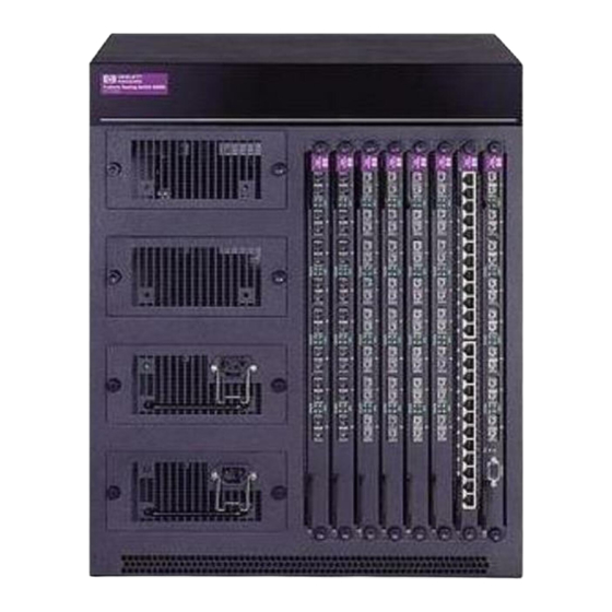
Page 178: Fixed -Port Switch Hp 6208M-Sx
CLI management and eight 100Mbps SX fiber ports for connection to Gigabit Ethernet links. The HP 6308M-SX routing switch provides both Layer 2 switching and Layer 3 routing in a single device and supports all of the most popular standards-based protocols—IP, IP/RIP, IPX, OSPF, BGP4, and AppleTalk. HP routing switches also support two IP multicasting protocols—Distance Vector Multicast Routing Protocol (DVMRP) - Page 179 Layer 2 Architecture When a packet arrives at an HP 6208M-SX switch, a search for the MAC destination address is initiated. If the MAC destination address is found, the packet’s priority is determined. The packet is then forwarded to the appropriate output port.
-
Page 180: Physical View
Physical View This section describes the external features of the HP 9304M, HP 9308M, HP 6308M-SX, and HP 6208M-SX. 1000BaseSX or 1000BaseLX ports 10BaseT/100BaseTX ports Link Activity Link Activity Link Activity Power Supply (redundant) Figure 8.17 Example front panel of an HP 9304M routing switch... -
Page 181: Ac Power Connector
Installation and Getting Started Guide NOTE: The rear panel of the HP 9308M and HP 9304M Chassis devices provide no network or power connections and therefore are not shown. Slot and Port Numbers The port numbers on all Fixed-port devices and Chassis devices are labeled on the hardware. However, the method you use to enter or select a port number differs depending on whether you are managing a Fixed-port device or a Chassis device. - Page 182 The Chassis devices, the HP 9304M and HP 9308M, come standard with four fans. The HP 9304M also comes standard with four fans. The HP 9308M comes standard with six fans. LEDs Each device is equipped with LEDs that denote port and power supply status. The tables below reflect the different port and expansion module port states.
- Page 183 1000BaseT Gigabit Copper (GC) Ports The 1000Base-T Gigabit Copper ports can provide Gigabit throughput over standard Cat-5 copper wiring. The port connectors are RJ-45s, the same as the connectors on HP’s 10/100 modules. Thus, you can immediately deploy the GC ports without recabling.
-
Page 184: Ac Power Supply
VAC power supply rated at 5 – 2.5A and 50 – 60 Hz. The HP 9304M and HP 9308M routing switches are equipped with an autoranging 100 – 120/200 – 240 VAC power supply rated at 8A/4A and 50 – 60 Hz. The green LED on the power supply is lit when the power supply is properly supplying 5-volt power to the system. -
Page 185: Reset Button
These systems come standard with two power supplies. Chassis Devices The HP 9304M comes standard with one power supply, which is enough to provide adequate power for any combination of modules. You can order an additional power supply for redundancy. -
Page 186: Configuring Basic Features
“Configuring IP” chapter in the Advanced Configuration and Management Guide. HP switches and routing switches are configured at the factory with default parameters that allow you to begin using the basic features of the system immediately. However, many of the advanced features such as VLANs or routing protocols for the routing switch must first be enabled at the system (global) level before they can be configured. -
Page 187: Using The Web Management Interface For Basic Configuration Changes
The Web management interface enables you to easily make numerous configuration changes by entering or changing information on configuration panels such as the one shown in Figure 9.1. This example is for a routing switch. The HP 6208M-SX does not have routing options but does have some additional options not available on routing switches. -
Page 188: Entering System Administration Information
When you configure a system name, the name replaces the default system name in the CLI command prompt. For example, if the system is an HP 9304M or HP 9308M, the system name you configure replaces “HP 9304M or HP 9308M” in the command prompt. - Page 189 Oakland(config)# snmp-server location Centerville Oakland(config)# end Oakland# write memory Syntax: hostname <string> NOTE: On the HP 9304M, HP 9308M, and HP 6308M-SX, you also can use the chassis name command to set the device name. Syntax: snmp-server contact <string> Syntax: snmp-server location <string>...
-
Page 190: Configuring Simple Network Management (Snmp) Parameters
Specifying an SNMP Trap Receiver You can specify a trap receiver to ensure that all SNMP traps sent by the HP device go to the same SNMP trap receiver or set of receivers, typically one or more host devices on the network. When you specify the host, you also specify a community string. - Page 191 Specifying a Single Trap Source You can specify a single trap source to ensure that all SNMP traps sent by the HP device use the same source IP address. When you configure the SNMP source address, you specify the Ethernet port, loopback interface, or virtual interface that is the source for the traps.
- Page 192 The following commands configure an IP interface on an Ethernet port and designate the address as the SNMP trap source for a routing switch. The HP device always sends traps through the Ethernet port and the source IP address of the traps is always the first IP address configured on the Ethernet port.
- Page 193 Disabling Syslog Messages and Traps for CLI Access HP devices send Syslog messages and SNMP traps when a user logs into or out of the User EXEC or Privileged EXEC level of the CLI. The feature applies to users whose access is authenticated by an authentication-method list based on a local user account, RADIUS server, or TACACS/TACACS+ server.
-
Page 194: Configuring An Interface As The Source For All Telnet Packets
If your Telnet server is configured to accept packets only from specific links or IP addresses, you can use this feature to simplify configuration of the Telnet server by configuring the HP device to always send the Telnet packets from the same link or source address. -
Page 195: Specifying A Simple Network Time Protocol (Sntp) Server
You can configure switches and routing switches to consult SNTP servers for the current system time and date. NOTE: HP switches and routing switches do not retain time and date information across power cycles. Unless you want to reconfigure the system time counter each time the system is reset, Hewlett-Packard recommends that you use the SNTP feature. - Page 196 To display information about SNTP associations, enter the following command: HP9300# show sntp associations address ref clock ~207.95.6.102 0.0.0.0 ~207.95.6.101 0.0.0.0 * synced, ~ configured Syntax: show sntp associations The following table describes the information displayed by the show sntp associations command. Table 9.1: Output from the show sntp associations command This Field...
-
Page 197: Setting The System Clock
Setting the System Clock In addition to SNTP support, HP switches and routing switches also allow you to set the system time counter. The time counter setting is not retained across power cycles and is not automatically synchronized with an SNTP server. - Page 198 Although SNTP servers typically deliver the time and date in Greenwich Mean Time (GMT), you can configure the switch or routing switch to adjust the time for any one-hour offset from GMT or for one of the following U.S. time zones: •...
-
Page 199: Configuring The Syslog Service
The device writes the messages to a local buffer that can hold up to 100 messages. You also can specify the IP address or host name of up to six SyslogD servers. When you specify a SyslogD server, the HP device writes the messages both to the system log and to the SyslogD server. - Page 200 The SyslogD service on a Syslog server receives logging messages from applications on the local host or from devices such as a routing switch or switch. SyslogD adds a time stamp to each received message and directs messages to a log file. Most Unix workstations come with SyslogD configured. Some third party vendor products also provide SyslogD running on NT.
- Page 201 Changing the Log Facility The SyslogD daemon on the SyslogD server uses a facility to determine where to log the messages from the HP device. The default facility for messages the HP device sends to the SyslogD server is “user”. You can change the facility using the following command.
-
Page 202: Displaying The Syslog Configuration
• local7 – reserved for local use Displaying the Syslog Configuration To display the Syslog parameters currently in effect on an HP device, enter the following command from any level of the CLI: HP9300> show logging Syslog logging: enabled (0 messages dropped, 0 flushes, 0 overruns) - Page 203 Clearing the Syslog Messages from the Local Buffer To clear the Syslog messages stored in the HP device’s local buffer, enter the following command from the Privileged EXEC level the CLI:...
-
Page 204: Changing The Default Gigabit Negotiation Mode
Click on the checkbox next to System Logging to place a checkmark in the box. Click Apply to clear the log. Changing the Default Gigabit Negotiation Mode You can configure the default Gigabit negotiation mode to be one of the following: •... -
Page 205: Limiting Broadcast, Multicast, Or Unknown-Unicast Rates
9-47. Limiting Broadcasts To limit the number of broadcast packets an HP device can forward each second, use the following CLI method. USING THE CLI To globally limit the number of broadcast packets an HP 9304M or HP 9308M routing switch forwards to 100,000... -
Page 206: Configuring Cli Banners
HP devices can be configured to display a greeting message on users’ terminals when they enter the Privileged EXEC CLI level or access the device through Telnet. In addition, an HP device can display a message on the Console when an incoming Telnet CLI session is detected. -
Page 207: Setting A Message Of The Day Banner
Setting a Message of the Day Banner You can configure the HP device to display a message on a user’s terminal when he or she establishes a Telnet CLI session. For example, to display the message “Welcome to HP 9304M or HP 9308M!” when a Telnet CLI... -
Page 208: Configuring Basic Port Parameters
Red – indicates there is no link. • Green – indicates the link is good. This example shows the port states for an HP 9304M or HP 9308M routing switch that has not yet been connected to the rest of the network. Configuring Basic Features... -
Page 209: Assigning A Port Name
Installation and Getting Started Guide Click on the Copy or Modify button next to a row of port information to display a configuration panel for that port. • Select Modify to change parameters for a port. • Select Copy to apply a port’s parameter settings to another port. Here is an example of the Port configuration panel. -
Page 210: Modifying Port Speed
USING THE WEB MANAGEMENT INTERFACE Log on to the device using a valid user name and password for read-write access. The System configuration panel is displayed. Click on the plus sign next to Configure in the tree view to display the configuration options. Select the Port link to display the Port table. -
Page 211: Modifying Port Mode
The port can be made inactive (disable) or active (enable) by selecting the appropriate status option. The default value for a port is enabled. USING THE CLI To disable port 8 on module 1 of an HP Chassis device, enter the following: HP9300(config)# interface e 1/8 HP9300(config-if-1/8)# disable... -
Page 212: Disabling Or Re-Enabling Flow Control
Syntax: enable You also can disable or re-enable a virtual interface. To do so, enter commands such as the following: HP9300(config)# interface ve v1 HP9300(config-vif-1)# disable Syntax: disable To re-enable a virtual interface, enter the enable command at the Interface configuration level. For example, to re-enable virtual interface v1, enter the following command: HP9300(config-vif-1)# enable Syntax: enable... -
Page 213: Changing The 802.3X Gigabit Negotiation Mode
Installation and Getting Started Guide Select the Save link at the bottom of the dialog. Select Yes when prompted to save the configuration change to the startup-config file on the device’s flash memory. Changing the 802.3x Gigabit Negotiation Mode The globally configured Gigabit negotiation mode for 802.3x flow control is the default mode for all Gigabit ports. You can override the globally configured default and set individual ports to the following: •... -
Page 214: Enabling/Disabling Layer 2 Switching
Enabling or Disabling Layer 2 Switching (routing switches only) By default, HP routing switches support Layer 2 switching. These devices switch the routing protocols that are not supported on the devices. If IPX routing is not enabled, then IPX traffic also is switched. By default IPX routing is disabled. -
Page 215: Changing The Mac Age Time
Select the Advance link. Enter the new age in the Switch Age Time field. You can enter a value from 0 – 65535. Click Apply to save the changes to the device’s running-config file. 9 - 30... -
Page 216: Configuring Static Mac Entries
This section describes how to configure static MAC addresses. NOTE: HP routing switches also support the assignment of static IP Routes, static ARP, and static RARP entries. For details on configuring these types of static entries, see the “Configuring IP” chapter in the Advanced Configuration and Management Guide. -
Page 217: Enabling Port-Based Vlans
Installation and Getting Started Guide Enter or edit the MAC address, if needed. Specify the address in the following format: xx-xx-xx-xx-xx-xx. Change the VLAN number if needed by editing the value in the VLAN ID field. Select the port number from the Slot (for Chassis devices) and Port pulldown lists. Select a QoS level from 0 –... -
Page 218: Assigning Ieee 802.1Q Tagging To A Port
USING THE WEB MANAGEMENT INTERFACE To enable port-based VLANs on the switch or routing switch: Log on to the device using a valid user name and password for read-write access. The System configuration panel is displayed. Select the box next to Port, next to Policy Based VLANs. -
Page 219: Configuring Trunk Groups
The Trunk Group feature allows you to establish multiple high-speed load-sharing links between two HP switches or routing switches or between an HP switch or routing switch and a server. You can configure from 2 – 4 ports as a trunk group, supporting transfer rates of up to 4 Gbps of bi-directional traffic. -
Page 220: Trunk Group Rules
– 20, 21 – 22, 23 – 24 NOTE: You can configure up to 12 trunk groups on an HP 9304M or HP 9308M 24-port 10/100 module. The 24-port 10/100 modules have the following primary ports: 1, 3, 5, 7, 9, 11, 13, 15, 17, 19, 21, and 23. - Page 221 Figure 9.4 shows some examples of valid 2-port trunk group links between devices. The trunk groups in this example are switch trunk groups, between two HP devices. Ports in a valid 2-port trunk group on one device are connected to two ports in a valid 2-port trunk group on another device. The same rules apply to 4-port trunk groups.
- Page 222 Configuring Basic Features Figure 9.5 shows example of two Chassis devices connected by multi-slot trunk groups. Figure 9.5 Examples of multi-slot trunk groups 9 - 37...
-
Page 223: Additional Trunk Group Rules For Gigabit Ethernet Modules On Chassis Devices
• Server trunk group – Use this type of trunk group to connect an HP switch or routing switch to a file server or single host device. The HP device load shares across the ports in the trunk group. - Page 224 NOTE: Hewlett-Packard recommends that you reload the software immediately after saving a trunk group configuration to the startup-config file, before making further configuration changes. If the device at the other end of the trunk group is another Layer 2 or routing switch, repeat Step 2 for the other device.
- Page 225 HP9304# reload Syntax: trunk server | switch ethernet <portnum> to <portnum> You then configure the trunk group on the HP ProCurve Switch 4000M. For more information, see the documentation for the HP ProCurve Switch 4000M. USING THE NETWORK MANAGEMENT INTERFACE To configure ports 5 –...
- Page 226 Example 2: Configuring a Trunk Group That Spans Multiple Gigabit Ethernet Modules in a Chassis Device To configure a trunk group that spans two modules in an HP 9304M or HP 9308M Chassis device, use one of the following methods.
- Page 227 Installation and Getting Started Guide HP9300# reload NOTE: HP recommends that you reload the software immediately after saving a trunk group configuration to flash memory, before making further configuration changes. Syntax: trunk [server | switch] ethernet <primary-portnum> to <portnum> ethernet <primary-portnum> to <portnum>...
-
Page 228: Modifying Trunk Group Membership
11. Select the Reload link and select Yes when the Web management interface asks you whether you really want to reload the software. 12. If the other end of the trunk group is a switch or routing switch, log in to the other device and follow the steps above. - Page 229 Select Server if you are connecting the trunk group ports to a server. Otherwise, the software assumes you are connecting the trunk group ports to another switch or routing switch and uses the default value Switch. Click the Modify button.
-
Page 230: Deleting A Trunk Group
Select the Reload link and select Yes when the Web management interface asks you whether you really want to reload the software. NOTE: If the other end of the trunk group is a switch or routing switch, log in to the other system and follow the applicable steps above. - Page 231 • Server – The trunk group is connected to a server. • Switch – The trunk group is connected to another switch or routing switch. The ports in the trunk group. The mode of the port, which can be one of the following: •...
- Page 232 Enabling IP Multicast Traffic Reduction By default, the HP 6208M-SX forwards all IP multicast traffic out all ports except the port on which the traffic was received. To reduce multicast traffic through the switch, you can enable IP Multicast Traffic Reduction. This feature configures the switch to forward multicast traffic only on the ports attached to multicast group members.
- Page 233 The default mode is passive. • Active – When active IGMP mode is enabled, an HP switch actively sends out IGMP queries to identify IP multicast groups on the network and makes entries in the IGMP table based on the Group Membership reports received from the network.
- Page 234 Disabling IGMP on Individual Ports By default, when you enable IP multicast on the HP 6208M-SX, all ports on the switch are configured for IGMP. If you are using active IGMP, all ports can send IGMP queries and receive IGMP reports. If you are using passive IGMP, all ports can receive IGMP queries.
- Page 235 Modifying the Age Interval When the HP 6208M-SX receives a Group Membership report, the switch makes an entry in the IGMP group table for the group in the report. The age interval specifies how long the entry can remain in the table without the switch receiving another Group Membership report.
-
Page 236: Index-
Configuring Basic Features USING THE WEB MANAGEMENT INTERFACE You cannot configure this feature using the Web management interface. Defining MAC Address Filters MAC layer filtering enables you to build access lists based on MAC layer headers in the Ethernet/IEEE 802.3 frame. - Page 237 Installation and Getting Started Guide The <dest-mac> <mask> | any parameter specifies the destination MAC address. The syntax rules are the same as those for the <src-mac> <mask> | any parameter. Use the etype | llc | snap argument if you want to filter on information beyond the source and destination address. The MAC filter allows for you to filter on the following encapsulation types: •...
- Page 238 • If a MAC filter is already configured and you are adding a new one, click on the Add MAC Filter link to display the MAC Filter configuration panel, as shown in the following example. • If you are modifying an existing MAC filter, click on the Modify button to the right of the row describing the filter to display the MAC Filter configuration panel, as shown in the following example.
-
Page 239: Enabling Logging Of Packets Denied By Mac Filters
Enabling Logging of Packets Denied by MAC Filters You can configure the HP device to generate Syslog entries and SNMP traps for packets that are denied by Layer 2 MAC filters. You can enable logging of denied packets on a global basis or an individual port basis. -
Page 240: Defining Broadcast And Multicast Filters
Defining Broadcast and Multicast Filters You can filter Layer 2 broadcast and multicast packets on specific ports. • Layer 2 broadcast packets have the value “FFFFFFFFFFFF” (all ones) in the destination MAC address field. You can configure broadcast filters for all types of IP packets or for UDP packets. •... -
Page 241: Configuring A Layer 2 Multicast Filter
Installation and Getting Started Guide HP9300(config-bcast-filter-id-1)# write memory To configure two filters, one to filter IP UDP traffic on ports 1/1 – 1/4, and the other to filter all broadcast traffic on port 4/6, enter the following commands: HP9300(config)# broadcast filter 2 ip udp HP9300(config-bcast-filter-id-2)# exclude-ports ethernet 1/1 to 1/4 HP9300(config-bcast-filter-id-3)# exit HP9300(config)# broadcast filter 3 any... -
Page 242: Enabling Or Disabling Routing Protocols
Select the Save link at the bottom of the dialog. Select Yes when prompted to save the configuration change to the startup-config file on the device’s flash memory. Enabling or Disabling Routing Protocols HP routing switches support the following protocols: • •... -
Page 243: Displaying And Modifying System Parameter Default Settings
CLI. USING THE CLI To enable a protocol on an HP routing switch, enter router at the global CONFIG level, followed by the protocol to be enabled. The following example shows how to enable OSPF: HP9300(config)# router ospf... - Page 244 • AppleTalk zones The tables you can configure and the defaults and valid ranges for each table differ depending on the HP device you are configuring. NOTE: If you increase the number of sub-net addresses you can configure on each port to a higher amount, you might also need to increase the total number of sub-nets that you can configure on the device.
- Page 245 To increase the number of IP sub-net interfaces you can configure on each port on a routing switch from 24 to 64, then increase the total number of IP interfaces you can configure on the device from 256 to 512, enter the...
-
Page 246: Assigning A Mirror Port And Monitor Ports
EXAMPLE: Suppose you want to diagnose the in and out traffic on port 3 on a module in slot 4 of an HP 9304M or HP 9308M, and use port 1 in slot 4 as the mirror port. To do so, enter the following:... -
Page 247: Displaying The Current Mirror And Monitor Port Configuration
USING THE WEB MANAGEMENT INTERFACE EXAMPLE: Suppose you want to diagnose the in and out on traffic on port 3 on a module in slot 4 of an HP 9304M or HP 9308M using port 1 in slot 4. To do so: Log on to the device using a valid user name and password for read-write access. -
Page 248: Hardware Specifications
This appendix lists the hardware specifications for the HP 9304M, HP 9308M, and HP 6208M-SX routing switches and the HP 6208M-SX switch. Electrical Specifications Table A.1: Electrical specifications Device Input Voltage Range HP 6208M-SX 100 – 240 VAC HP 6308M-SX... -
Page 249: Storage Environment
Installation and Getting Started Guide Storage Environment • Storage Temperature: -40° – 158° F, -40° – 70° C • Storage Humidity: 95% maximum, non-condensing • Storage Altitude: 10,000 feet (3,000 meter) maximum Electromagnetic Emissions • FCC Class A, Part 15, Subpart B •... -
Page 250: Software Specifications
RFC support • Internet drafts support Standards Compliance The HP 9304M, HP 9308M, and HP 6208M-SX routing switches and the HP 6208M-SX switch support the following standards. NOTE: The routing protocol standards apply only to the routing switches. • IEEE 802.3, 10BaseT •... -
Page 251: Rfc Support
Installation and Getting Started Guide RFC Support The following table lists the RFCs supported by the HP 9304M, HP 9308M, and HP 6208M-SX routing switches and the HP 6208M-SX switch. NOTE: Some devices support only a subset of the RFCs. For example, the HP 6208M-SX switch does not support router-specific RFCs. - Page 252 RFC Number 1213 MIB II Definitions 1215 SNMP generic traps 1256 ICMP Router Discovery Protocol (IRDP) 1267 Border Gateway Protocol version 4 (BGP4) MIB 1340 Assigned numbers (where applicable) 1354 IP Forwarding Table MIB 1398 Ethernet-Like MIB 1493 Bridge MIB (excluding filtering of objects) 1541 and Dynamic Host Configuration Protocol (DHCP) 1542...
-
Page 253: Internet Drafts
Installation and Getting Started Guide RFC Number 2385 TCP MD5 Signature Option (for BGP4) 2439 BGP Route Flap Dampening 2453 Route Information Protocol (RIP) version 2 2796 BGP Route Reflection 2842 BGP Capability Advertisement 2858 BGP Multi-protocol Extension Internet Drafts In addition to the RFCs listed in “RFC Support”... - Page 254 1000BaseSx 8-10 1000BaseT 8-10 100BaseFx 8-10 100BaseFx Ports 8-10 100BaseTx 8-10 10BaseT 8-10 802.3x Gigabit negotiation 9-28 9304M Routing Switch 2-8 9308M Routing Switch 2-8 AC power 8-11 connector 8-8 Access CLI 2-21 augmenting privilege level 3-9 local user account 3-11...
- Page 255 Installation and Getting Started Guide Chassis architecture 8-5 hardware overview 8-1 module 8-1 name 9-3 poll interval 5-19 replacing power supply 2-6 slot and port numbers 8-8 specifications A-1 swapping modules 2-4 CLI 7-7 access 2-21 access levels 2-12 attaching serial cable 2-9 command completion 2-22 CONFIG Level 2-12 line editing commands 2-22...
- Page 256 overview 8-5 specifications A-1 Flash code downloading 6-1 image name 7-1 uploading 6-1 version 7-2 Flow control disabling 9-27 Gateway default 2-14 Getting Help 1-3 Gigabit negotiation 9-19, 9-28 Global CONFIG Level 2-12 Grounding ii, 2-3 Half-duplex mode 9-26 Handles, Warning 2-1, 2-3 Hardware architecture 8-5 fan 8-8...
- Page 257 Installation and Getting Started Guide address filter 9-51 address lock 9-57 static entries 9-31 switching 7-15 Management module redundant 5-1 Manual nomenclature 1-1 Mask, Network 2-1 Memory port buffer 8-8 Message TFTP error 6-8 Mirror port 9-61 Mode port 9-26 Module 8-1 connectors 2-18 installing 2-4...
- Page 258 Query IGMP disabling 9-49 Query interval IP multicast Layer 2 9-47 Rack installation chassis 2-15 fixed-port device 2-16 Rack Mounting 2-3, 2-16 warning 2-3, 2-15 Rack, Loading 2-3 RADIUS 3-1, 3-31 Read-only community string 7-8 Read-write community string 7-8 no default 3-13 Redundant link trunk group 9-34 Redundant management module 5-1...
- Page 259 Installation and Getting Started Guide Super User 2-12 Swapping modules 2-4 Switch age time 9-30 architecture 8-6 configuring basic Layer 2 parameters 9-29 disabling 9-29 Layer 2 7-15 Switchover redundant management module 5-2 Syslog messages 5-9 Syslog 7-12, 9-14 buffer 9-16, 9-18...
- Page 260 Technical information in this document is subject to change without notice. ©Copyright Hewlett-Packard Company 2000. All rights reserved. Reproduction, adaptation, or translation without prior written permission is prohibited except as allowed under the copyright laws. Printed in U.S.A. 12/00 Manual Part Number 5969-2362...
Need help?
Do you have a question about the PROCURVE 6208M-SX and is the answer not in the manual?
Questions and answers