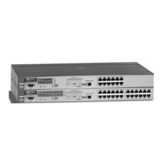
HP ProCurve Switch 212M Management And Configuration Manual
Hewlett-packard procurve switch management and configuration guide
Hide thumbs
Also See for ProCurve Switch 212M:
- Management and configuration manual (690 pages) ,
- Installation and configuration manual (504 pages) ,
- Installation and getting started manual (348 pages)

Subscribe to Our Youtube Channel
Related Manuals for HP ProCurve Switch 212M


Summary of Contents for HP ProCurve Switch 212M
- Page 1 HP ProCurve Switch 212M and 224M For world-wide support on all HP Network Connectivity Products visit our web site at: http://www.hp.com/go/network_city Less Work, More Network Management and Configuration Guide...
- Page 3 HP ProCurve Switch 212M and 224M Management and Configuration Guide...
- Page 4 Hewlett-Packard. Warranty See the Customer Support/Warranty booklet included with the product. A copy of the specific warranty terms applicable to your Hewlett-Packard products and replacement parts can be obtained from your HP Sales and Service Office or authorized dealer.
-
Page 5: Table Of Contents
Advantages of Using the Switch Console ......1-3 HP TopTools for Hubs & Switches ......1-4 2 Configuring an IP Address on the Switch Methods for Configuring an IP Address and Subnet Mask . - Page 6 Rebooting the Switch ........
- Page 7 Overview ........... . . 7-1 Switch Console Status and Counters Menu ..... 7-2 General System Information .
- Page 8 Using the SNMP-Based HP Download Manager ....A-5 Switch-to-Switch Download ....... . . A-5 Troubleshooting TFTP Downloads .
- Page 9 Base MAC Address ......... B-2 Switch Port MAC Addresses ....... . . B-3...
-
Page 11: Selecting A Management Interface
(chapter 4), and how to configure the switch using either interface (chapter 6). To use HP TopTools for Hubs & Switches, refer to the HP TopTools User’s Guide and the TopTools online help, both of which are available on the CD-... -
Page 12: Advantages Of Using The Hp Web Browser Interface
Advantages of Using the HP Web Browser Interface Advantages of Using the HP Web Browser Interface Figure 1-1. Example of the HP Web Browser Interface Display Easy access to the switch from anywhere on the network, using the device’s IP address Familiar browser interface--locations of window objects consistent with known standard, uses mouse clicking for navigation;... -
Page 13: Advantages Of Using The Switch Console
Figure 1-2. Example of the Switch Console Display More comprehensive set of features and parameters to work with than the web browser interface Out-of-band access (through direct cable connection) to switch, so network bottlenecks, crashes, and network downtime do not slow or prevent access... -
Page 14: Hp Toptools For Hubs & Switches
HP TopTools for Hubs & Switches HP TopTools for Hubs & Switches You can operate HP TopTools from a network management station on the network to monitor traffic, manage your hubs and switches, and proactively recommend network changes to increase network uptime and optimize performance. - Page 15 Monitors, stores, and analyzes network traffic to determine where upgrades are needed Uses Network Performance Advisor to give clear, easy-to-follow plans detailing the most cost-effective way to upgrade your network Selecting a Management Interface HP TopTools for Hubs & Switches...
-
Page 17: Configuring An Ip Address On The Switch
For more information on this topic, refer to “IP Configuration” on page 6-5. N o t e An IP address and subnet mask for the switch should be assigned by your network administrator and be compatible with the IP addressing used in your network. -
Page 18: Methods For Configuring An Ip Address And Subnet Mask
This section describes how to use the switch console to configure an IP address. Use the instructions in chapter 2, “Installing the Switch 212M and 224M” of your switch installation manual to connect a PC running a terminal emulator, or a terminal, to the Console port on the switch, and display the Main Menu. - Page 19 Press [Enter], then [S] (for Save), then proceed with any other console tasks. To test the IP address, you can try a Ping test to the switch’s IP address from another IP device in your network.
-
Page 20: Where To Go From Here
To continue to use the switch console, refer to chapter 4, “Using the Switch Console”. To access the switch using a network management tool, refer to chapter 5, “Using HP TopTools to Monitor and Manage the Switch”. Inbound Telnet access to the switch is enabled in the factory default configuration. -
Page 21: Using The Hp Web Browser Interface
Using the HP Web Browser Interface Overview The HP web browser interface built into the switch lets you easily access the switch from a browser-based PC on your network. This lets you do the following: optimize your network uptime by using the Alert Log and other diagnostic... -
Page 22: Web Browser Interface Requirements
PC Operating System UNIX® Operating System HP TopTools for Hubs & Switches (Optional) For notes on using Netscape and Microsoft web browsers, go to HP’s Network City web site, http://www.hp.com/go/network_city. Supported Network Devices and System Requirements Minimum 90 MHz Pentium... -
Page 23: Starting An Hp Web Browser Interface Session
PC or workstation. For HP TopTools requirements, refer to the information printed on the sleeve in which the HP TopTools CD is shipped, or to the system requirements information in the user’s guide included on the HP TopTools CD. -
Page 24: Using Hp Toptools For Hubs & Switches
3-1 on the next page. Using HP TopTools for Hubs & Switches For more on installing and using HP TopTools for Hubs & Switches, refer to the HP TopTools for Hubs & Switches booklet and CD-ROM that came with your switch. - Page 25 The web browser interface automatically starts with the Status Overview window displayed for the selected device, as shown in figure 3-1. First Time Install Alert Alert Log Figure 3-1. Status Overview Screen Using the HP Web Browser Interface Starting an HP Web Browser Interface Session...
-
Page 26: Tasks For Your First Hp Web Browser Interface Session
Using the HP Web Browser Interface Tasks for Your First HP Web Browser Interface Session Tasks for Your First HP Web Browser Interface Session The first time you access the web browser interface, there are three tasks that you should perform: review the “First Time Install”... - Page 27 Using the HP Web Browser Interface Tasks for Your First HP Web Browser Interface Session This window is the launching point for the basic configuration you need to perform to set web browser interface passwords to maintain security and Fault Detection policy, which determines the types of messages that will be displayed in the Alert Log.
-
Page 28: Creating User Names And Passwords In The Web Browser Interface
Using the HP Web Browser Interface Tasks for Your First HP Web Browser Interface Session Creating User Names and Passwords in the Web Browser Interface You may want to create both a user name and password to create access security for your switch. There are two levels of access to the interface that can be controlled by setting user names and passwords: operator. - Page 29 If a user name has not been set, the User Name field in the web browser interface access popup must be left blank. The switch console uses only the passwords and does not prompt you for the User Names.
-
Page 30: Online Help For The Hp Web Browser Interface
3-4 on page 3-11. The switch is shipped with the URL set to the HP World Wide Web site. However, if HP TopTools for Hub & Switches is installed on a management station in your network, and TopTools discovers your switch, the Management Server URL value is automatically changed to point to the management station to retrieve the help. - Page 31 Figure 3-4. How To Access Web Browser Interface Online Help If you do not have HP Top Tools for Hubs & Switches installed on a computer in your network, and you do not have an active connection to the World Wide Web, then online help for the web browser interface will not be available.
-
Page 32: The Web Browser Interface Screen Layout
Using the HP Web Browser Interface The Web Browser Interface Screen Layout The Web Browser Interface Screen Layout This section describes the elements of the web browser interface screen layout starting with the first screen you see, the Status, Overview window. - Page 33 Status, Alert Name, the date and time the Alert was reported by the switch, and a short description of the alert. You can double click on any of the entries in the log and get a detailed description.
-
Page 34: The Port Utilization And Status Displays
The Port Utilization and Status Displays The Port Utilization and Status displays show an overview of the status of the switch and the amount of network activity on each port. The following figure shows a sample reading of the Port Utilization and Port Status. - Page 35 3-8. Figure 3-8. Display of Numerical Values for the Bar Using the HP Web Browser Interface The Web Browser Interface Screen Layout 3-15...
-
Page 36: The Alert Log
Note that the Port Fault- Disabled symbol will be displayed in the legend only if one or more of the ports is in that status. See chapter 7, “Monitoring and Analyzing Switch Operation” for more information. - Page 37 The Alert and Description columns are sorted alpha- betically, while the Status column is sorted by severity type, with more critical severity indicators appearing above less critical indicators. Using the HP Web Browser Interface The Web Browser Interface Screen Layout 3-17...
-
Page 38: Alert Types
N o t e When troubleshooting the sources of alerts, it may be helpful to also check the switch’s Port Status and Port Counters windows (page 7-7 and page 7-9 respectively) and the Event Log in the switch console (page 8-6). - Page 39 Acknowledge Event – removes the New symbol from the log entry Delete Event – removes the alert from the Alert Log Retest Button – polls the switch again to determine whether or not the alert can be regenerated. Cancel Button – closes the detail view with no change to the status of the alert and returns you to the Overview screen.
- Page 40 Using the HP Web Browser Interface The Web Browser Interface Screen Layout The Alert Control Bar The Alert Control Bar appears at the bottom of the Alert Log and contains buttons that enable you to manage the Overview Window. Figure 3-11. The Alert Control Bar The buttons in the control bar are: Refresh –...
-
Page 41: The Tab Bar
Product is the switch product name. Version is the software (operating system) version currently running in the switch. IP Address is the IP address assigned to the switch. Manage- ment Server is the currently assigned Management Server URL (page 6-4). - Page 42 Support tab, and the URL for the source of online Help for the web browser interface (page 6-3). The Support URL is configured to automatically access HP’s Network City website on the World Wide Web. However, if you have an internal support structure, you may wish to change the Support URL to access that structure.
- Page 43 Figure 3-16. The Diagnostics Tab and Buttons This tab displays the Diagnostics Button Bar which contains buttons that enable you to perform troubleshooting tasks for your switch. The buttons are: Ping/Link Test. Enables you to send test packets to devices connected to a port, using both the IP address (Ping) and the MAC address (Link) as criteria for a valid connection.
-
Page 44: The Status Bar
Table 3-3. System Name. The name you have configured for the switch in the Identity screen or through the switch console System Information screen. Most Critical Alert Description. A short text description of the earliest, unacknowledged alert with the current highest severity in the Alert Log. -
Page 45: Setting Fault Detection Policy
Setting Fault Detection Policy One of the powerful features in the browser interface is the Fault Detection facility. For your switch, this feature controls the types of alerts reported to the Alert Log based on their level of severity. Set this policy in the Fault Detection Window, shown in figure 3-16. - Page 46 Medium Sensitivity High Sensitivity The Fault Detection settings are: High Sensitivity. This policy directs the switch to send all alerts to the Alert Log. This setting is most effective on networks that have no or few problems. Medium Sensitivity. (the default setting) This policy directs the switch to send alerts related to network problems to the Alert Log.
-
Page 47: Using The Switch Console
The console gives you access to all switch config- uration parameters; the web browser interface gives you access to a subset of these. Refer to chapter 3, “Using the HP Web Browser Interface” and chapter 6, “Configuring the Switch”. -
Page 48: Starting And Ending A Console Session
Switch 212M or 224M (as described in chapter 1, “Installa- tion” of the HP Switch 212M and 224M Installation Guide) or that you have already configured an IP address on the switch so you can start a Telnet session with the switch. -
Page 49: How To End A Console Session
N o t e The Switch 212M and 224M serial interface does not support all modem lines, including automatic disconnect. As a result, if you are concerned about security for console access, in addition to using passwords, you should always make sure you select the Logout option from the Main Menu to terminate the console session. -
Page 50: Main Menu Features
(Refer to chapter 6, “Configuring the Switch”.) This feature is available only in Manager Mode console sessions. If you access the console at the Operator level... - Page 51 (Refer to appendix A, “Transferring an Operating System or Configuration”.) • Logout: Terminates the console session and disconnects Telnet access to the switch. (Refer to “How To End a Console Session” on page 4-3.) Using the Switch Console Main Menu Features...
-
Page 52: Screen Structure And Navigation
Using the Switch Console Screen Structure and Navigation Screen Structure and Navigation Console screens include these three elements: Parameter fields and/or read-only information such as statistics Navigation and configuration actions, such as Save, Edit, and Cancel Help line to describe navigation options, individual parameters, and read-... - Page 53 Cancel action). Note: Most parameter changes are activated when you execute Save, and it is therefore not necessary to reboot the switch after making these changes. But if an asterisk appears next to any menu item you reconfigure, it is necessary to reboot the switch to implement the change.
- Page 54 Using the Switch Console Screen Structure and Navigation To get full screen Help. In all screens except the Command Prompt screen there is a Help option in the Actions line. Press [H] to select the Help action, and a separate help screen is displayed.
-
Page 55: Using Password Security
Access to the Status and Counters menu, the Event Log, and the Diagnostics menu, but no configuration capabilities. On the Operator level, the Configuration menus, Download OS, and Reboot Switch options in the Main Menu, and the Command Prompt option in the Diagnostics menu are not available. To use password security: Set a Manager password (and an Operator password, if applicable for your system) as described on page 4-10. -
Page 56: To Set Manager And Operator Passwords
If there is only a Manager password set (with no Operator password), and the Manager password is not entered correctly when the console session begins, the switch operates on the Operator level. If there are both a Manager password and an Operator password, but neither is entered correctly, access to the console will be denied. - Page 57 To Delete Password Protection (Including Recovery from a Lost Password): This procedure deletes both passwords (Manager and Opera- tor). If you have physical access to the switch, press the Clear button on the front of the switch to clear all password protection, then enter new passwords as described earlier in this chapter.
-
Page 58: Rebooting The Switch
To Reboot the switch, use the Reboot Switch option in the Main menu. (Note that the Reboot Switch option is not available if you log on in Operator mode; that is, you enter an Operator password at the password prompt.) Reboot Switch option Figure 4-5. - Page 59 Rebooting To Activate Configuration Changes. Configuration changes for some parameters become effective as soon as you save them. However, you must reboot the switch in order to implement any changes to the param- eters on the Console/Serial Link screen (under Switch Management Access Configuration menu).
-
Page 60: Using The Command Prompt
Using the Switch Console Using the Command Prompt Using the Command Prompt In addition to the menu-based part of the console interface, under the Diag- nostics Menu, a command-line based interface is available. The commands are primarily for the expert user and for diagnostics purposes. Selecting Command Prompt from the Diagnostics Menu presents a command prompt from which you can enter commands. -
Page 61: Using Hp Toptools To Monitor And Manage The Switch
Windows. HP TopTools for Hubs & Switches provides complete control of your Switch 212M or 224M through its graphical interface. In addition, it makes use of the HP Extended RMON and standard RMON agent software that is on the switch to provide powerful but easy to use traffic monitoring and network activity analysis tools. -
Page 62: Snmp Management Features
The switch SNMP agent also uses certain variables that are included in a Hewlett-Packard proprietary MIB file you can add to the SNMP database in your network management tool. You can copy the MIB file from the HP TopTools for Hubs & Switches CD, shipped with your switch, or from following World Wide Web site: http://www.hp.com/go/network_city... -
Page 63: Snmp Configuration Process
IP Address on the Switch” for more information.) Configure the appropriate SNMP communities. (The “public” community exists by default and is used by HP’s network management applications.) (For more on configuring SNMP communities, refer to “SNMP Communi- ties” on page 6-15.) Configure the appropriate trap receivers. -
Page 64: Advanced Management: Rmon And Hp Extended Rmon Support
Advanced Management: RMON and HP Extended RMON Support Advanced Management: RMON and HP Extended RMON Support The switch supports RMON (Remote Monitoring) and HP Extended RMON on all connected network segments. This allows for troubleshooting and optimizing of your network. -
Page 65: Configuring The Switch
This chapter describes the switch configuration features available in both the switch console and the web browser interface. If you need information on how to operate either the web browser interface or the switch console, refer Chapter 3, “Using the HP Web Browser Interface”... -
Page 66: Configuration Features
Configuring the Switch Overview Configuration Features The following table lists the configuration features available for the switch. Table 6-1. Feature Time Protocol IP Configuration SNMP Communities Trap Receivers and Authentication Traps Console/Serial Link: • Inbound Telnet • Web Agent Enabled •... -
Page 67: Support/Management Urls Feature
- the URL of the network management server or other source of the online help files for this web browser interface – the default is a location on HP’s World Wide Web site Figure 6-1. The Support/Mgmt URLs Window... -
Page 68: Management Server Url
The default URL is: http://www.hp.com/rnd/device_help which is the location on HP’s World Wide Web site of the help files for the web browser interface. To use this site, you must have a modem link or other access to the World Wide Web operating when you run the web browser interface. -
Page 69: Ip Configuration
The switch console screen enables you to configure the initial values for: IP address, subnet mask, and (optionally) the gateway address for the switch so that it can be managed in an IP network from the web browser interface, SNMP-based network management station, or by the switch console through a Telnet session. -
Page 70: Configuring Ip Address From The Web Browser Interface
Configuring the Switch IP Configuration Configuring IP Address from the Web Browser Interface Figure 6-2. Configuring IP Addressing on the Web Browser Interface 1. Click here. 3.To enable manual entry 4. Enter an IP address, subnet mask, and, if needed, the IP address of the default gateway. - Page 71 • Disabled: Network management access to the switch over IP is disabled. IP Address IP address for the switch IP interface. If DHCP/Bootp is selected for IP Configuration, this is a read-only field displaying the value received from a DHCP or Bootp server.
-
Page 72: Configuring Ip Address From The Switch Console
To use the console, set the IP Config parameter to Manual and then manually enter the IP address and subnet mask you want for the switch. If you plan to use DHCP or Bootp, use the console to ensure that the IP Config parameter is set to DHCP/Bootp, then refer to “DHCP/Bootp... -
Page 73: How Ip Addressing Affects Switch Operation
Without an IP address and subnet mask compatible with your network, your control of the switch is limited to what you can do through a direct console connection, and some of the switch features will not be available. To be able... -
Page 74: Dhcp/Bootp Operation
N o t e The Switch 212M and Switch 224M are compatible with both DHCP and Bootp servers. Once the switch acquires an IP configuration from either a DHCP or Bootp server, it displays the IP address, subnet mask, and gateway information in the IP Configuration screen. - Page 75 As a result, the IP addressing provided by the server may be different each time the switch reboots or renews its configuration from the server. This may cause a problem for you if you access the switch through the web browser interface, since the IP address is used as the browser URL.
- Page 76 T144 N o t e The above Bootp table entry is a sample that will work for the Switch 212M and 224M when the appropriate addresses and file names are used. There are other features and parameters that can be implemented with Bootp. See the documentation for your Bootp server for more information.
- Page 77 Press [Enter] to exit from edit mode, then press [S] to save the configuration change. When you press [S] to save the configuration change or reboot the switch with DHCP/Bootp enabled in a network providing DHCP/Bootp service, it will do...
-
Page 78: Globally Assigned Ip Network Addresses
Configuring the Switch IP Configuration Globally Assigned IP Network Addresses If you intend to connect your network to other networks that use globally administered IP addresses, Hewlett-Packard strongly recommends that you use IP addresses that have a network address assigned to you. There is a formal process for assigning unique IP addresses to networks worldwide. -
Page 79: Snmp Communities
Manager Address field. Entering one or more IP addresses in the Manager Address field restricts access to only those addresses. For more on this topic, refer to chapter 5, “Using HP TopTools To Monitor and Manage Your Network”, and to the console online help. - Page 80 SNMP Communities To View, Edit, or Add SNMP Communities: From the Main Menu, select: 2. Switch Management Access Configuration (IP, SNMP, Console)... 2. SNMP Community Names/Authorized Managers Figure 6-4. The SNMP Communities Screen (Default Values) From the Configuration screen, select SNMP Communities to display a screen similar to the one above.
- Page 81 View and Access levels configured for that community. If you want to limit access to the switch, you can enter up to ten IP addresses of authorized management stations into the Manager Address field. Entering the IP addresses in the Manager Address field limits access to only those addresses.
-
Page 82: Trap Receivers
If the Send Authentication Traps field is set to Yes, an authentication trap is sent to the addresses on the screen if any management station attempts an unau- thorized access of the switch. Check the event log to help determine why the authentication trap was sent. (Refer to “Using the Event Log To Identify Problem Sources”... - Page 83 [>] or [Tab] to move the cursor to the Address field. Type in the IP address of a network management station to which you want the switch to send SNMP trap packets, then press [>] or [Tab] to move the cursor to the Community field.
-
Page 84: Console/Serial Link
N o t e : If you change the Baud Rate or Flow Control settings for the switch, you should make the corresponding changes in your console access device. Oth- erwise, you may lose connectivity between the switch and your terminal emulator due to differences between the terminal and switch settings for these two parameters. -
Page 85: Using The Switch Console To Configure The Console/Serial Link
Refer to the online help provided with this screen for further information on configuration options for these features. When you have finished making changes to the above parameters, press [Enter], then press [S] (for Save) and return to the Switch Management Access Configuration menu. Configuring the Switch... -
Page 86: System Information
Configuring the Switch System Information System Information From the web browser interface and switch console you can configure basic switch management information, including system data, address table aging, and time zone parameters. Configuring System Parameters from the Web Browser Interface In the web browser interface, you can enter the system information shown below. -
Page 87: Configuring System Information From The Console
Refer to the online help provided with this screen for further information on configuration options for these features. When you have finished making changes to the above parameters, press [Enter], then press [S] (for Save) and return to the Switch Configuration menu. Configuring the Switch... -
Page 88: Port Settings
Configuring the Switch Port Settings Port Settings From the web browser interface and switch console you can configure the operating state for each switch port. The following table shows the settings available for each port type. The same parameter settings are available in both the web browser interface and the switch console. - Page 89 It is recommended that if you use this flow control method, it should be configured only on those ports that are connected to a single end node, not on ports that are connected to a switch, hub, bridge, or router.
-
Page 90: Configuring Port Parameters From The Web Browser Interface
Configuring the Switch Port Settings Configuring Port Parameters from the Web Browser Interface 2. Click Here Clicking on 5. Select configuration changes. Figure 6-10. Example of Port Configuration and Modify Selected Ports Windows 6-26 1. Click Here 3. Click on a port to select it for configuration. -
Page 91: Configuring Port Parameters From The Switch Console
Or, refer to the online help provided with this screen. When you have finished making changes to the above parameters, press [Enter], then press [S] (for Save) and return to the Switch Configuration menu. Configuring the Switch... -
Page 92: Network Monitoring Port Features
Network Monitoring Port Features From the web browser interface and switch console you can designate a port for monitoring traffic on one of the other switch ports. The monitoring is accomplished by copying all traffic from the specified monitored port to the designated monitoring port. -
Page 93: Configuring Port Monitoring From The Switch Console
Configuring Port Monitoring from the Switch Console To Access Port Monitoring: From the Main Menu, select: 3. Switch Configuration... 3. Network Monitoring Port Figure 6-13. Network Monitoring Port Configuration Screen In the Actions menu, press [E] (for Edit). If monitoring is currently disabled (the default) then enable it by pressing the Space bar (or [Y]) to select Yes). -
Page 94: Spanning Tree Protocol (Stp)
This results in duplication of messages, leading to a “broadcast storm” that can bring down the network. -
Page 95: Enabling Stp From The Web Browser Interface
Enabling STP from the Web Browser Interface This procedure enables or disables STP on the switch. 1. Click Here 3. To enable or disable STP, click on the drop-down menu, and click on your selection (On or Off). Figure 6-14. Device Features Screen for Enabling Spanning Tree... -
Page 96: Using The Switch Console To Configure Stp
Configuring the Switch Spanning Tree Protocol (STP) Using the Switch Console To Configure STP In most cases, the default STP parameter settings are adequate. In cases where they are not, use this procedure to make configuration changes. C a u t i o n... -
Page 97: How Stp Operates
Cost and Priority for each port, as well as the global STP parameter values for the switch. In the event of a topology change such as a switch, bridge, or data link failure in the network, STP develops a new spanning tree that may result in changing some ports from the blocking state to the forwarding state. -
Page 98: Ip Multicast (Igmp) Service Features-Multimedia Traffic Control
Switches in the network that support IGMP can then be configured to direct the multicast traffic to only the ports where needed. In addition to the Switch 212M and Switch 224M, other HP switches that support IGMP include: • HP Switch 1600M •... -
Page 99: Configuring Igmp From The Web Browser Interface
Default: Off When Off, all ports on the switch simply forward IP multicast traffic. When On, the feature enables each port on the switch to detect IGMP queries and report packets, and to manage IP multicast traffic. When you use the web browser Interface to enable Multicast Filtering,... -
Page 100: Using The Switch Console To Configure Igmp
Using the Switch Console To Configure IGMP In the factory default configuration, IGMP is disabled. When you use either the console or the web browser interface to enable IGMP on the switch, the switch forwards IGMP traffic only to ports belonging to multicast groups. - Page 101 Use [v] to highlight the Forward with High Priority parameter. If you want IGMP traffic to be forwarded with a higher priority than other traffic on the switch, use the Space bar to select Yes. Otherwise, leave this parameter set to No.
-
Page 102: How Igmp Operates
[Enter] and [S] (for Save) to activate the changes you’ve made to the IGMP configuration and return to the Advanced Features menu. (It is not necessary to reboot the switch. The new IGMP configuration is implemented when you select “Save” in step 8.) How IGMP Operates The Internet Group Management Protocol (IGMP) is an internal protocol of the Internet Protocol (IP) suite. - Page 103 Figure 6-19 on page page 6-40 shows a network running IGMP. PCs 1 and 4, Switch #2, and all of the routers are members of an IP multicast group. (The routers operate as queriers.) Switch #1 ignores IGMP traffic and does not distinguish between IP multicast group members and non-members.
- Page 104 Figure 6-19. The Advantage of Using IGMP The next figure (6-20) shows a network running IP multicasting using IGMP without a multicast router. In this case, the IGMP-configured switch runs as a querier. PCs 2, 5, and 6 are members of the same IP multicast group.
- Page 105 PC #1 Figure 6-20. Isolating IP Multicast Traffic in a Network In the above figure, the multicast group traffic does not go to switch 1 and beyond because either the port on switch 3 that connects to switch 1 has been configured as blocked or there are no hosts off of switch 1 or switch 2 that belong to the multicast group.
-
Page 106: Special Case Igmp Configuration
Microsoft the multicast group before they start sending the multicast data stream. Because these applications operate in this way, the Switch 212M and 224M will not be able to recognize the server as part of the multicast group, and will disable the multicast communication between the server and the client mem- bers of the multicast group. - Page 107 If your switch, and not some other device, is acting as the querier, the above procedure will have to be completed. IP Multicast (IGMP) Service Features—Multimedia Traffic Control 1.
-
Page 109: Monitoring And Analyzing Switch Operation
Monitoring and Analyzing Switch Operation Overview You can use the switch console (and, in some cases, the web browser inter- face) to access read-only status and counter information to help you monitor, analyze, and troubleshoot switch operation. This chapter describes the status and counters screens available through the switch console and/or the web browser interface. -
Page 110: Switch Console Status And Counters Menu
Monitoring and Analyzing Switch Operation Switch Console Status and Counters Menu Switch Console Status and Counters Menu To display the switch console Status and Counters menu, from the console Main Menu select: 1. Status and Counters Figure 7-1. The Status and Counters Menu Each of the above menu items accesses the read-only screens described on the following pages. -
Page 111: General System Information
To access this screen from the console Main Menu, select: 1. Status and Counters 1. General System Information Figure 7-2. Example of General Switch Information This screen dynamically indicates how individual switch resources are being used. See the online Help for details. -
Page 112: Switch Management Address Information
To access this screen from the Main Menu, select: 1. Status and Counters 2. Switch Management Address Information Figure 7-3. Example of Management Address Information This screen displays addresses that are important for management of the switch. See the online Help for details. -
Page 113: Port Status
Monitoring and Analyzing Switch Operation Port Status Port Status The web browser interface and the switch console show the same port status data. Displaying Port Status from the Web Browser Interface 2. Click here 1. Click here Figure 7-4. Example of Port Status on the Web Browser Interface... -
Page 114: Displaying Port Status From The Switch Console
Monitoring and Analyzing Switch Operation Port Status Displaying Port Status from the Switch Console To access this screen from the Main Menu, click on: 1. Status and Counters 3. Port Status Figure 7-5. Example of Port Status on the Console Interface... -
Page 115: Port Counters
Port Counters The web browser interface and the switch console show the same port counter data. These screens enable you to determine the traffic patterns for each port. Port Counter features include: Dynamic display of counters summarizing the traffic on each port since the last reboot or reset Option to reset the counters to zero (for the current console session). -
Page 116: Displaying Port Counters From The Web Browser Interface
Monitoring and Analyzing Switch Operation Port Counters Displaying Port Counters from the Web Browser Interface 1. Click here Clicking on the Figure 7-6. Example of Port Counters and Details on the Web Browser Interface 2. Click here 3. To view details about the traffic on a particular port, highlight that port number, then click on Details for Select Port. -
Page 117: Displaying Port Counters From The Console Interface
Monitoring and Analyzing Switch Operation Port Counters Displaying Port Counters from the Console Interface To access this screen from the Main Menu, click on: 1. Status and Counters 4. Port Counters Figure 7-7. Example of Port Counters on the Console Interface To view details about the traffic on a particular port, highlight that port number (figure 7-7), then select Show Details. - Page 118 Monitoring and Analyzing Switch Operation Port Counters Figure 7-8. Example of the Display for Show details on a Selected Port This screen also includes the Reset action. Refer to the note on page 7-7. 7-10...
-
Page 119: Address Table
5. Address Table Figure 7-9. Example of the Address Table This screen lets you determine which switch port is being used to communi- cate with a specific device on the network. The listing includes: The MAC addresses that the switch has learned from network devices... -
Page 120: Port Address Table
Port Address Table This screen lets you determine which devices are attached to the selected switch port by listing all of the MAC addresses detected on that port. To access the port address table: From the Main Menu click on: 1. - Page 121 Figure 7-11. Example of a Port Address Table for a Specific Port Use the Search action at the bottom of the screen to determine whether a specific device (MAC address) is connected to the selected port. Monitoring and Analyzing Switch Operation Port Address Table action.
-
Page 122: Spanning Tree (Stp) Information
To access the Spanning Tree Information screen from the Main Menu, click on: 1. Status and Counters 7. Spanning Tree Information STP must be enabled on the switch to display the following data: Figure 7-12. Example of Spanning Tree Information Use this screen to determine current switch-level STP parameter settings and statistics. - Page 123 You can use the Show ports action at the bottom of the screen to display port- level information and parameter settings for each port in the switch (including port type, cost, priority, operating state, and designated bridge) as shown in figure 7-13.
-
Page 124: Ip Multicast (Igmp) Status
1. Status and Counters 8. Advanced Features Status This screen identifies the active IP multicast groups the switch has detected, along with the number of report packets and query packets seen for each group. It also indicates which port is used for connecting to the querier. - Page 125 IGMP devices connected to the switch via the port are hosts, routers, or both.) To do so, select the group from the above screen and press [S] for Show ports. For example, suppose you wanted to view the status of the IP multicast group 224.0.1.24 shown in the above screen.
-
Page 127: Troubleshooting
Troubleshooting This chapter addresses performance-related network problems that can be caused by topology, switch configuration, and the effects of other devices or their configurations on switch operation. (For switch-specific information on hardware problems indicated by LED behavior, cabling requirements, and other potential hardware-related problems, refer to the installation guide you received with the switch.) -
Page 128: Troubleshooting Approaches
Installation Guide shipped with the switch for cable types and connector pin-outs. Use HP TopTools for Hubs & Switches (if installed on your network) to help isolate problems and recommend solutions. HP TopTools is shipped at no extra cost with the switch. -
Page 129: Web Browser Interface Or Switch Console Access Problems
Console port and from the Status and Counters Menu, select 2. Switch Management Address Information. If you are using DHCP to acquire the IP address for the switch, the IP address “lease time” may have expired so that the IP address has changed. -
Page 130: Unusual Network Activity
Unusual network activity is usually indicated by the LEDs on the front of the switch or as indicated by measurements from the switch console or from a network management tool such as the HP TopTools for Hubs & Switches. Refer to the installation guide you received with the switch for information on using LEDs to identify unusual network activity. - Page 131 IGMP-Related Problems IP Multicast (IGMP) Traffic Does Not Reach IGMP Hosts or a Multicast Router Connected to a Port. IGMP must be enabled on the switch and the affected port must be configured for “Auto” or “Forward” operation. IP Multicast Traffic Floods Out All Ports; IGMP Does Not Appear To Filter Traffic.
-
Page 132: Using The Event Log To Identify Problem Sources
(warning) indicates that a service has behaved unexpectedly. (critical) indicates that a severe switch error has occurred. (debug) reserved for HP internal diagnostic information. Date is the date in mm/dd/yy format that the entry was placed in the log. Time is the time in hh:mm:ss format that the entry was placed in the log. - Page 133 Table 8-2. System Description Module addrMgr Address table bootp Bootp addressing chassis switch hardware console switch console dhcp DHCP addressing download file transfer fault Web browser interface Alert Log igmp IP Multicast IP-related Novell Netware Entering and Navigating in the Event Log Display. From the Main Menu, select 4.
- Page 134 The switch is reset using the Reset button. Power to the switch is interrupted. A new operating system is downloaded to the switch. The event log is not erased by using the Reboot Switch command in the Main Menu. Event Log Control Keys Action Advance the display by one page (next page).
-
Page 135: Diagnostics
To respond to a Ping test or a Link test, the device you are trying to reach must be IEEE 802.3-compliant. Ping Test. This is a test of the path between the switch and another device on the same or another IP network that can respond to IP packets. (“Ping” is an acronym for “Packet INternet Groper”.) If the network device responds... - Page 136 Destination IP/MAC Address is the network address of the target, or destination, device to which you want to test a connection with the switch. An IP address is in the X.X.X.X format where X is a decimal number between 0 and 255. A MAC address is made up of 12 hexadecimal digits, for example, 08000c-070a00.
- Page 137 Executing Ping or Link Tests from the Switch Console From the console Main Menu, select: 5. Diagnostics . . . 1. Link Test 2. Ping Test Figure 8-4. Examples of Link Test and Ping Test Screens Do one of the following: For a Link test, enter the MAC address of the target device.
- Page 138 Troubleshooting Diagnostics The console displays the result of each test. For example, if a Link test succeeds, you will see Linktest Command Successful. If the Link test fails, you will see Linktest Command Timed out. If a Ping test succeeds, you will see a message indicating the target IP address is “alive”, along with a test counter and elapsed time for each test.
-
Page 139: The Configuration File
The Configuration File The complete switch configuration is contained in a file that you can browse from either the web browser interface or the switch console. It may be useful in some troubleshooting scenarios to view the switch configuration. Browsing the Configuration File from the Web Browser... - Page 140 Troubleshooting Diagnostics Browsing the Configuration File from the Switch Console To use the switch condole to display the configuration file that is currently saved: From the console Main Menu, select: 5. Diagnostics 3. Browse Configuration File Figure 8-6. Example of the Browse Configuration Display...
-
Page 141: Using The Command Prompt
Using the Command Prompt In addition to the menu-based part of the switch console, under the Diagnos- tics Menu, a command-line based interface is available. The commands are primarily for the expert user and for diagnostics purposes. Selecting Command Prompt from the Diagnostics Menu presents a command prompt from which... -
Page 142: Restoring The Factory Default Configuration
Continue to press the Clear button while releasing the Reset button. When the Self Test LED begins to flash, release the Clear button. The switch will then complete its self test and begin operating with the configuration restored to the factory default settings. -
Page 143: A File Transfers
(OS) code to the switch: TFTP transfer method (page A-2) Xmodem transfer method (page A-4) HP’s SNMP Download Manager included in HP TopTools for Hubs & Switches (page A-5) A switch-to-switch file transfer (page A-5) N o t e Downloading a new OS does not change the current switch configuration. -
Page 144: Using Tftp To Download The Os File
This procedure assumes that: An OS file for the switch has been stored on a TFTP server accessible to the switch. (The OS file is typically available from HP’s electronic ser- vices—see the Customer Support/Warranty booklet shipped with the switch.) The switch is properly connected to your network and has already been configured with a compatible IP address and subnet mask. - Page 145 Figure 8-2. Example of the Download OS Screen During a Download A “progress” bar indicates the progress of the download. When the entire operating system has been received, all activity on the switch halts and the following messages appear: Transfer completed Validating and writing system software to FLASH...
-
Page 146: Using Xmodem To Download The Os File
Using Xmodem to Download the OS File This procedure assumes that: The switch is connected via the Console port to a PC operating as a terminal. (Refer to the Installation Guide you received with the switch for information on connecting a PC as a terminal and running the switch console interface.) -
Page 147: Using The Snmp-Based Hp Download Manager
From the switch console Main Menu in the switch to receive the down- load, select 7. Download OS. Select Method: TFTP. In the TFTP Server field, enter the IP address of the remote Switch 212M or 224M containing the OS you want to download. Enter “os” in the Remote File Name field. -
Page 148: Troubleshooting Tftp Downloads
Figure 8-3. Example of Message for TFTP Download Failure To find more information on the cause of a download failure, examine the messages in the switch’s Event Log. (See “Event Log” on page 8-6.) Some of the causes of download failures include: Incorrect or unreachable address specified for the TFTP Server parameter. - Page 149 N o t e If an error occurs in which normal switch operation cannot be restored, the switch automatically reboots itself. In this case, an appropriate message is displayed in the copyright screen that appears after the switch reboots. You can display the same information by selecting the Command Prompt option from the Diagnostics Menu and executing the History command.
-
Page 150: Transferring Switch Configurations
File Transfers Transferring Switch Configurations Transferring Switch Configurations You can use the following commands to transfer Switch 212M and Switch 224M configurations between the switch and a PC or Unix workstation. Command XGet XPut N o t e Get or Xget overwrites the switch’s current configuration with the down- loaded configuration. - Page 151 IP_address CONFIG remote_file where: IP address is the address of the PC or Unix workstation in which the configuration is to be stored. remote_file is the name of the configuration file in the PC or Unix workstation File Transfers Transferring Switch Configurations...
- Page 152 Also, the PC or workstation must be running an Xmodem-compatible terminal emulation program. If a manager password has been set, you must log on to the switch using that password in order to execute the Xget or Xput commands.
-
Page 153: B Mac Address Management
MAC address is assigned to each switch port Determining the MAC Addresses You can use the switch console to determine the base MAC address and the port MAC addresses for the switch. The methods are described in the rest of this appendix. -
Page 154: Base Mac Address
MAC Address Management Determining the MAC Addresses Base MAC Address The switch’s base MAC address is displayed on a sticker on the back of the switch. You can also use the switch console to display the switch’s base MAC address. -
Page 155: Switch Port Mac Addresses
Switch Port MAC Addresses The MAC address assigned to each switch port is used internally by such features as Flow Control, and the Spanning Tree Protocol. Determining the MAC address assignments for individual ports can be useful when diagnosing switch operation. To display these addresses, use the walkmib command at the switch console command prompt. - Page 157 … 3-14 maximum activity indicator … 3-15 non-unicast packet indicator … 3-14 unicast packet indicator … 3-14 base MAC address for the switch … B-2 baud rate … 4-2 blocked port, IGMP … 6-36 blocking state, spanning tree … 6-33 Bootp …...
- Page 158 Ping and link testing … 8-11 resetting the switch … 4-12 starting a session … 4-2 status and counters access … 4-4 switch management access configuration … 4-4 console configuration screen … 6-20 console session … 4-2 Control Bar Alert Log … 3-13 copyright screen …...
- Page 159 … 4-6 location on screens … 4-6 History command … A-7 HP proprietary MIB … 5-2 HP TopTools for Hubs & Switches … 5-1 managing the switch with … 5-2 IEEE 802.1d … 6-30, 6-32 IGMP … 6-34 configuring … 6-36, 6-38 console configuration …...
- Page 160 … A-6 switch-to-switch … A-5 TFTP method … A-2 troubleshooting … A-6 Xmodem method … A-4 overview of the switch console … 4-1 Overview window, web browser interface active button … 3-13 active tab … 3-13 Alert Log … 3-13 Alert Log control bar …...
- Page 161 Reset button … 8-8 restoring factory default configuration … 8-16 reset port counters … 7-7 resetting the switch erases the Event Log … 8-8 factory default reset … 8-16 from the console … 4-12 restricted access, SNMP … 6-15 restricted write access … 6-15 RFC 1213 …...
- Page 162 Ping and link testing … 8-11 resetting the switch … 4-12 starting a session … 4-2 status and counters access … 4-4 switch management access configuration … 4-4 switch management access configuration … 4-4 switch support information, location specification … 6-3 switch-to-switch download …...
- Page 163 … 3-13 unicast activity display … 3-14 using IP address to access … 3-4 web site accessing HP for MIB file … 5-2 write access … 6-15 Xget command … A-8 Xmodem OS download … A-4 XPut command … A-8...
- Page 166 Technical information in this document is subject to change without notice. ©Copyright Hewlett-Packard Company 1998. All rights reserved. Reproduction, adaptation, or translation without prior written permission is prohibited except as allowed under the copyright laws. Printed in Singapore 6/98 Manual Part Number 5967-2146 *5967-2146*...
Need help?
Do you have a question about the ProCurve Switch 212M and is the answer not in the manual?
Questions and answers