
Related Manuals for Mitsubishi Electric A1SD75P1-S3


Summary of Contents for Mitsubishi Electric A1SD75P1-S3
- Page 1 sales@artisantg.com artisantg.com (217) 352-9330 | Click HERE Find the Mitsubishi AD75P3 at our website:...
- Page 2 A1SD75P1-S3/P2-S3/P3-S3 A1SD75P1-S3/P2-S3/P3-S3 Positioning Module Positioning Module AD75P1-S3/P2-S3/P3-S3 AD75P1-S3/P2-S3/P3-S3 User s Manual User s Manual A1SD75/AD75S3-U-E MODEL MODEL 13J871 CODE IB(NA)-66716-F(0305)MEE HEAD OFFICE : 1-8-12, OFFICE TOWER Z 14F HARUMI CHUO-KU 104-6212,JAPAN NAGOYA WORKS : 1-14 , YADA-MINAMI 5-CHOME , HIGASHI-KU, NAGOYA , JAPAN When exported from Japan, this manual does not require application to the Ministry of Economy, Trade and Industry for service transaction permission.
-
Page 3: Safety Instructions
SAFETY INSTRUCTIONS (Always read these instructions before using this equipment.) Before using this product, please read this manual and the relevant manuals introduced in this manual carefully and pay full attention to safety to handle the product correctly. The instructions given in this manual are concerned with this product. For the safety instructions of the programmable logic controller system, please read the CPU module User's Manual. - Page 4 [Design Instructions] CAUTION Do not bundle or adjacently lay the control wire or communication cable with the main circuit or power wire. Separate these by 100mm or more. Failure to observe this could lead to malfunctioning caused by noise. [Mounting Instructions] CAUTION Use the PLC within the general specifications environment given in this manual.
- Page 5 [Startup/Maintenance Instructions] CAUTION Never disassemble or modify the module. Failure to observe this could lead to trouble, malfunctioning, injuries or fires. Always turn all phases of the power supply OFF externally before installing or removing the module. Failure to turn all phases OFF could lead to module trouble or malfunctioning. Before starting test operation, set the parameter speed limit value to the slowest value, and make sure that operation can be stopped immediately if a hazardous state occurs.
-
Page 6: Revisions
This manual confers no industrial property rights or any rights of any other kind, nor does it confer any patent licenses. Mitsubishi Electric Corporation cannot be held responsible for any problems involving industrial property rights which may occur as a result of using the contents noted in this manual. -
Page 7: Table Of Contents
INTRODUCTION Thank you for purchasing the Mitsubishi general-purpose programmable logic controller MELSEC-A Series. Always read through this manual, and fully comprehend the functions and performance of the A Series PLC before starting use to ensure correct usage of this product. CONTENTS SAFETY INSTRUCTIONS..........................A-1 REVISIONS ..............................A-4... - Page 8 3.3.3 AD75 auxiliary functions and common functions ................3-8 3.3.4 Combination of AD75 main functions and auxiliary functions ............3-10 3.4 Specifications of input/output signals with PLC CPU ................3-12 3.4.1 List of input/output signals with PLC CPU..................3-12 3.4.2 Details of input signals (AD75 PLC CPU) ...................
- Page 9 5.2.1 Basic parameters 1 ........................... 5-18 5.2.2 Basic parameters 2 ........................... 5-24 5.2.3 Detailed parameters 1........................5-28 5.2.4 Detailed parameters 2........................5-36 5.2.5 Zero point return basic parameters ....................5-45 5.2.6 Zero point return detailed parameters ....................5-52 5.3 List of positioning data ..........................5-56 5.4 List of start block data ..........................
- Page 10 SECTION 2 CONTROL DETAILS AND SETTING 8. ZERO POINT RETURN CONTROL 8-1 to 8-26 8.1 Outline of zero point return control ......................8-2 8.1.1 Two types of zero point return control ....................8-2 8.2 Machine zero point return .......................... 8-4 8.2.1 Outline of the machine zero point return operation................
- Page 11 10.1.2 "Start block data" and "condition data" configuration..............10-4 10.2 Advanced positioning control execution procedure ................10-6 10.3 Setting the start block data ........................10-7 10.3.1 Relation between various controls and start block data ..............10-7 10.3.2 Block start (normal start) ........................ 10-8 10.3.3 Condition start ..........................
- Page 12 Appendix 3 Positioning data (No. 1 to 100), List of buffer memory addresses ......Appendix-13 Appendix 4 Connection examples with servo amplifiers manufactured by MITSUBISHI Electric Corporation ................Appendix-16 Appendix 4.1 Connection example of A1SD75/AD75 and MR-H A (Differential driver (Open collector)) ...............Appendix-16 Appendix 4.2 Connection example of A1SD75/AD75 and MR-J2/J2S- A...
- Page 13 Appendix 9.1 Comparisons with AD71 (S1), AD71S2 (A1SD71S2) models ......Appendix-23 Appendix 9.2 Comparisons with A1SD75P1/A1SD75P2/A1SD75P3, and AD75P1/ AD75P2/ AD75P3 models ...............Appendix-24 Appendix 9.3 Comparisons with old versions of A1SD75P1-S3/A1SD75P2-S3/ A1SD75P3-S3, and AD75P1-S3/AD75P2-S3/AD75P3-S3 models......Appendix-25 Appendix 10 MELSEC Explanation of positioning terms ..............Appendix-26 Appendix 11 Positioning control troubleshooting ................Appendix-46...
-
Page 14: About Manuals
(Enclosed with module) A1SD75P1-S3/P2-S3/P3-S3 Positioning Module User's Manual (Hardware) IB-66732 The A1SD75P1-S3/P2-S3/P3-S3 positioning module performance specifications, input/output interface, (13J882) names of each part and startup procedures, etc., are explained. (Enclosed with module) Positioning Module Software Package type SW1IVD-AD75P Operating Manual The methods of creating data (parameters, positioning data, etc.), transmitting the data to the module,... -
Page 15: Using This Manual (1
Using This Manual (1) The symbols used in this manual are shown below. Pr.* ..Symbol indicating positioning parameter and zero point return parameter item. Da.* ..Symbol indicating positioning data, start block data and condition data item. Md.* ..Symbol indicating monitor data item. Cd.* .. -
Page 16: Using This Manual (2
Using This Manual (2) The methods for reading this manual are shown below. 1) → 2) → 3) → 4) → 5) → Test operation → 6) → Actual operation Chapter 1 PRODUCT OUTLINE 1) Understand the product functions and specifications, and design the system. -
Page 17: Using This Manual (3
Using This Manual (3) The contents of each chapter are shown below. SECTION 1 PRODUCT SPECIFICATIONS AND HANDLING 1 PRODUCT The basic contents for understanding positioning control using AD75 are OUTLINE described. 2 SYSTEM The devices required for positioning control using AD75 are described. CONFIGURATION 3 SPECIFICATIONS The AD75 functions and performance specifications, etc., are described. -
Page 18: Generic Terms And Abbreviations
Details of generic term/abbreviation PLC CPU Generic term for PLC CPU on which AD75 can be mounted. AD75 Generic term for positioning module AD75P1-S3, AD75P2-S3, AD75P3-S3, A1SD75P1-S3, A1SD75P2-S3, and A1SD75P3-S3. The module type is described to indicate a specific module. Peripheral device Generic term for DOS/V personal computer that can run the following "AD75 Software... -
Page 19: Enclosed Parts
AD75P2-S3 AD75P3-S3 External device connection connector (10136-3000VE, Sumitomo 3M) Connector cover (10336-56 F0-008, Sumitomo 3M) AD75 A1SD75P1-S3/P2-S3/P3-S3, AD75P1-S3/P2-S3/P3-S3 type Positioning Module User's Manual (Hardware) A - 17 Artisan Technology Group - Quality Instrumentation ... Guaranteed | (888) 88-SOURCE | www.artisantg.com... - Page 20 MEMO A - 18 Artisan Technology Group - Quality Instrumentation ... Guaranteed | (888) 88-SOURCE | www.artisantg.com...
- Page 21 SECTION 1 PRODUCT SPECIFICATIONS AND HANDLING SECTION 1 is configured for the following purposes (1) to (5). (1) To understand the outline of positioning control, and the AD75 specifications and functions (2) To carry out actual work such as installation and wiring (3) To set parameters and data required for positioning control (4) To create a sequence program required for positioning control (5) To understand the memory configuration and data transmission process...
- Page 22 MEMO Artisan Technology Group - Quality Instrumentation ... Guaranteed | (888) 88-SOURCE | www.artisantg.com...
-
Page 23: Product Outline
Chapter 1 PRODUCT OUTLINE The purpose and outline of positioning control using AD75 are explained in this chapter. By understanding "What can be done", and "Which procedures to use" beforehand, the positioning system can be structured smoothly. 1.1 Positioning control ......................1-2 1.1.1 Features of AD75....................1-2 1.1.2... -
Page 24: Positioning Control
1 PRODUCT OUTLINE MELSEC-A 1.1 Positioning control 1.1.1 Features of AD75 The features of the AD75 are shown below. (1) Lineup of 1-axis to 3-axis modules (a) There are six types of positioning modules for 1-axis to 3-axis control. Select according to the PLC CPU type and the required No. of control axes. (b) There is one slot used to mount each AD75 onto the base unit. - Page 25 1 PRODUCT OUTLINE MELSEC-A (d) The zero point return control has been strengthened. 1) The near-point dog type (one type), stopper stop type (three types), and count type (two types) zero point return methods have been prepared as the "machine zero point return" zero point return method. 2) To realize zero point return control to the machine zero point from a random position, the zero point return retry function has been prepared.
-
Page 26: Purpose And Applications Of Positioning Control
1 PRODUCT OUTLINE MELSEC-A 1.1.2 Purpose and applications of positioning control "Positioning" refers to moving a moving body, such as a workpiece or tool (hereinafter, generically called "workpiece") at a designated speed, and accurately stopping it at the target position. The main application examples are shown below. Punch press (X, Y feed positioning •... - Page 27 1 PRODUCT OUTLINE MELSEC-A Lifter (Storage of Braun tubes onto aging rack) • During the aging process of Braun tubes, Unloader storage onto the rack is carried out by Loader/unloader positioning with the servo. • The up/down positioning of the lifter is carried B conveyor Aging rack out with the 1-axis servo, and the horizontal...
-
Page 28: Mechanism Of Positioning Control
1 PRODUCT OUTLINE MELSEC-A 1.1.3 Mechanism of positioning control Positioning control using the AD75 is carried out with "pulse signals". (The AD75 is a module that generates pulses). In the positioning system using the AD75, various software and devices are used for the following roles. The AD75 realizes complicated positioning control when it reads in various signals, parameters and data and is controlled with the PLC CPU. - Page 29 1 PRODUCT OUTLINE MELSEC-A The principle of "position control" and "speed control" operation is shown below. Position control The total No. of pulses required to move the designated distance is obtained in the following manner. Designated distance Total No. of pulses No.
-
Page 30: Outline Design Of Positioning System
1 PRODUCT OUTLINE MELSEC-A 1.1.4 Outline design of positioning system The outline of the positioning system operation and design, using the AD75, is shown below. Positioning PLC CPU module AD75 Drive unit Servomotor Forward run pulse train Speed command Servo Devia- converter amplifier... - Page 31 1 PRODUCT OUTLINE MELSEC-A Servomotor speed Speed V Pulse droop Pulse amount distribution Accel- Decel- Time t eration eration Stop settling time Pulse train Rough Dense Rough Fig.1.3 AD75 output pulses A : Movement amount per pulse (mm/pulse) Vs : Command pulse frequency (pulse/s) n : Pulse encoder resolution (pulse/rev) Workpiece L : Worm gear lead (mm/rev)
-
Page 32: Communicating Signals Between Ad75 And Each Module
1 PRODUCT OUTLINE MELSEC-A 1.1.5 Communicating signals between AD75 and each module The outline of the signal communication between the AD75 and PLC CPU, peripheral device and drive unit, etc., is shown below. AD75 PLC CPU PLC READY signal Drive unit READY signal AD75 READY signal Upper/lower limit signal External... - Page 33 1 PRODUCT OUTLINE MELSEC-A AD75 Peripheral device The AD75 and peripheral device communicate the following data via the peripheral device connection connector. Direction AD75 Peripheral device Peripheral device AD75 Communication Parameter, positioning data, positioning Parameter, positioning data, positioning Data (read/write) start information start information Zero point return control start command...
-
Page 34: Flow Of System Operation
1 PRODUCT OUTLINE MELSEC-A 1.2 Flow of system operation 1.2.1 Flow of all processes The positioning control processes, using the AD75, are shown below. AD75 software GPP function soft- AD75 Servo, etc. PLC CPU package ware package Understand the functions and performance, and determine the positioning operation method Design (system design) Installation, wiring, single module test... - Page 35 1 PRODUCT OUTLINE MELSEC-A The following work is carried out with the processes shown on the left page. Details Reference • Chapter 1 • Chapter 2 Understand the product functions and usage methods, the configuration devices • and specifications required for positioning control, and design the system. Chapter 3 •...
-
Page 36: Outline Of Starting
1 PRODUCT OUTLINE MELSEC-A 1.2.2 Outline of starting The outline for starting each control is shown with the following flowchart. * It is assumed that each module is installed, and the required system configuration, etc., has been prepared. Flow of starting Installation and connection of module Preparation Setting of hardware... - Page 37 1 PRODUCT OUTLINE MELSEC-A Setting method : Indicates the sequence program that must be created. <AD75 software package> Set with AD75 software package Write * Set the parameter and data for executing this function, and the auxiliary functions that need to be set beforehand. AD75 <GPP function software package>...
-
Page 38: Outline Of Stopping
1 PRODUCT OUTLINE MELSEC-A 1.2.3 Outline of stopping Each control is stopped in the following cases. (1) When each control is completed normally. (2) When the drive unit READY signal is turned OFF. (3) When the PLC READY signal is turned OFF (When "parameter error" or "watch dog timer error"... -
Page 39: Outline For Restarting
1 PRODUCT OUTLINE MELSEC-A 1.2.4 Outline for restarting When a stop cause has occurred during operation with position control causing the axis to stop, positioning to the end point of the positioning data can be restarted from the stopped position by using the " Cd.13 Restart command". When "... - Page 40 1 PRODUCT OUTLINE MELSEC-A MEMO 1 - 18 Artisan Technology Group - Quality Instrumentation ... Guaranteed | (888) 88-SOURCE | www.artisantg.com...
-
Page 41: System Configuration
Chapter 2 SYSTEM CONFIGURATION In this chapter, the general image of the system configuration of the positioning control using AD75, the configuration devices, applicable CPU module and the precautions of configuring the system are explained. Prepare the required configuration devices to match the positioning control system. 2.1 General image of system ....................2-2 2.2 List of configuration devices...................2-4 2.3 Applicable system......................2-5... -
Page 42: General Image Of System
2 SYSTEM CONFIGURATION MELSEC-A 2.1 General image of system The general image of the system, including the AD75, PLC CPU and peripheral devices is shown below. (The Nos. in the illustration refer to the "No." in section "2.2 List of configuration devices". - Page 43 2 SYSTEM CONFIGURATION MELSEC-A Drive Motor unit Manual pulse generator Cable Machine system input (switch) · Near-point dog · Limit switch · External start signal · Speed/position changeover signal · Stop signal AD75TU Peripheral device AD75 software package SW1IVD Personal -AD75P computer SW0D5C...
-
Page 44: List Of Configuration Devices
Refer to the AD75 Software Package Operating Manual for details. Drive unit – (Prepared by user) (Prepared by user) Manual pulse – generator Recommended: MR-HDP01 (Mitsubishi Electric) AD75C20SH For MR-H Connection cable Cable for connecting AD75 with drive unit, manual AD75C20SJ2 For MR-J2/J2S-A (dedicated) pulse generator or machine system input signal. -
Page 45: Applicable System
When using the A73CPU(-S3), mount the AD75P1-S3, AD75P2-S3 or AD75P3-S3 on the extension base unit. Remote I/O station (MELSECNET/10, MELSECNET (II), MELSECNET/B) The AD75P1-S3/AD75P2-S3/AD75P3-S3 and A1SD75P1-S3/A1SD75P2- S3/A1SD75P3-S3 positioning modules are applicable for the data link system (MELSECNET (II)/B) and network system (MELSECNET/10) remote I/O station, with the exception of A0J2P25/R25 (remote I/O station). -
Page 46: Precautions For Configuring System
PLC CPU's No. of input/output points. Precautions according to module version Some AD75 cannot be used depending on the module version. Refer to "Appendix 9.3 Comparison with old version A1SD75P1-S3/A1SD75P2-S3/A1SD75P3-S3, AD75P1-S3/AD75P2-S3/AD75P3-S3" for details. 2 - 6 Artisan Technology Group - Quality Instrumentation ... Guaranteed | (888) 88-SOURCE | www.artisantg.com... - Page 47 2 SYSTEM CONFIGURATION MELSEC-A Precautions for using stepping motor When configuring the positioning system using a stepping motor, the following points must be observed. Refer to section "12.6.6 Stepping motor mode functions" for details. (1) Setting the stepping motor mode (a) When using a stepping motor with the AD75, the stepping motor mode must be set.
- Page 48 2 SYSTEM CONFIGURATION MELSEC-A MEMO 2 - 8 Artisan Technology Group - Quality Instrumentation ... Guaranteed | (888) 88-SOURCE | www.artisantg.com...
-
Page 49: Specifications And Functions
Chapter 3 SPECIFICATIONS AND FUNCTIONS The various specifications of the AD75 are explained in this chapter. The "General specifications", "Performance specifications", "List of functions", "Specifications of input/output signals with PLC CPU", and the "Specifications of input/output interfaces with external devices", etc., are described as information required when designing the positioning system. -
Page 50: General Specifications
3 SPECIFICATIONS AND FUNCTIONS MELSEC-A 3.1 General specifications The general specifications of the AD75 are given below. Item Specifications 0 to 55 ° C Working ambient temperature -20 to 75 ° C Storage ambient temperature Working ambient humidity 10 to 90% RH, with no dew condensation Storage ambient humidity 10 to 90% RH, with no dew condensation Frequency... -
Page 51: Performance Specifications
3 SPECIFICATIONS AND FUNCTIONS MELSEC-A 3.2 Performance specifications Model A1SD75P1-S3 A1SD75P2-S3 A1SD75P3-S3 Item AD75P1-S3 AD75P2-S3 AD75P3-S3 No. of control axes 1 axis 2 axes 3 axes 2-axis linear interpolation 2-axis linear interpolation Interpolation function None 2-axis circular interpolation 2-axis circular interpolation... -
Page 52: List Of Functions
3 SPECIFICATIONS AND FUNCTIONS MELSEC-A 3.3 List of functions 3.3.1 AD75 control functions The AD75 has several functions. In this manual, the AD75 functions are categorized and explained as follows. Main functions (1) Zero point return control "Zero point return control" is a function that established the start point for carrying out positioning control, and carries out positioning toward that start point. - Page 53 3 SPECIFICATIONS AND FUNCTIONS MELSEC-A Main functions Auxiliary functions Zero point return control Control registered in AD75 (Functions characteristic to machine zero point return) [Positioning start No.] Zero point return retry function [9001] Machine zero point return Zero point shift function [9002] High-speed zero point return <Functions that compensate...
-
Page 54: Ad75 Main Functions
3 SPECIFICATIONS AND FUNCTIONS MELSEC-A 3.3.2 AD75 main functions The outline of the main functions for positioning control with the AD75 are described below. (Refer to "SECTION 2" for details on each function.) Reference Main functions Details section Mechanically establishes the positioning start point with a near- Machine zero point return control point dog or stopper. - Page 55 3 SPECIFICATIONS AND FUNCTIONS MELSEC-A Reference Main functions Details section With one start, executes the positioning data in a random block Block start (Normal start) 10.3.2 with the set order. Carries out condition judgment set in the "condition data" for the designated positioning data, and then executes the "start block data".
-
Page 56: Ad75 Auxiliary Functions And Common Functions
3 SPECIFICATIONS AND FUNCTIONS MELSEC-A 3.3.3 AD75 auxiliary functions and common functions Auxiliary functions The functions that assist positioning control using the AD75 are described below. (Refer to "SECTION 2" for details on each function.) Reference Auxiliary function Details section This function retries the machine zero point return with the upper/lower limit switches during machine zero point return. - Page 57 3 SPECIFICATIONS AND FUNCTIONS MELSEC-A Reference Auxiliary function Details section This function temporarily stops the operation to confirm the positioning operation during debugging, etc. Step function 12.6.1 The operation can be stopped at each "automatic deceleration" or "positioning data". This function stops (decelerates to a stop) the positioning being Skip function executed when the skip signal is input, and carries out the next 12.6.2...
-
Page 58: Combination Of Ad75 Main Functions And Auxiliary Functions
3 SPECIFICATIONS AND FUNCTIONS MELSEC-A 3.3.4 Combination of AD75 main functions and auxiliary functions With positioning control using the AD75, the main functions and auxiliary functions can be combined and used as necessary. A list of the main function and auxiliary function combinations is given below. - Page 59 3 SPECIFICATIONS AND FUNCTIONS MELSEC-A Functions that Functions that limit Functions that change compensate Other functions control control details control – – – – – – – – – – – – – – – – – – – – –...
-
Page 60: Specifications Of Input/Output Signals With Plc Cpu
3 SPECIFICATIONS AND FUNCTIONS MELSEC-A 3.4 Specifications of input/output signals with PLC CPU 3.4.1 List of input/output signals with PLC CPU The AD75 uses 32 input points and 32 output points for exchanging data with the PLC CPU. The input/output signals for when the AD75 is mounted in slot No. 0 of the main base unit are shown below. -
Page 61: Details Of Input Signals (Ad75 Plc Cpu)
3 SPECIFICATIONS AND FUNCTIONS MELSEC-A 3.4.2 Details of input signals (AD75 PLC CPU) The ON/OFF timing and conditions, etc., of the input signals are shown below. Device Signal name Details • When the PLC READY signal [Y1D] turns from OFF to ON, the parameter setting OFF : READY AD75 READY complete... -
Page 62: Details Of Output Signals (Plc Cpu Ad75)
3 SPECIFICATIONS AND FUNCTIONS MELSEC-A 3.4.3 Details of output signals (PLC CPU AD75) The ON/OFF timing and conditions, etc., of the output signals are shown below. Device Signal name Details • Axis 1 Positioning OFF : No positioning Zero point return or positioning operation is started. start start request •... -
Page 63: Specifications Of Input/Output Interfaces With External Devices
3 SPECIFICATIONS AND FUNCTIONS MELSEC-A 3.5 Specifications of input/output interfaces with external devices 3.5.1 Electrical specifications of input/output signals Input specifications Rated input Working Input Response Signal name voltage/current voltage range voltage/current voltage/current resistance time Drive unit READY 19.2 to 17.5VDC or more/ 7VDC or less/ (READY) - Page 64 3 SPECIFICATIONS AND FUNCTIONS MELSEC-A Output specifications Max. load Rated load Working load Max. voltage Leakage Signal name current/rush Response time voltage voltage range drop at ON current at OFF current • Differential driver/open collector equivalent to Am26LS31 • The CW/CCW type, PULSE/SIGN type and A phase/B phase type are selected with the AD75 and drive unit parameter ( Pr.5 Pulse output mode).
-
Page 65: Signal Layout For External Device Connection Connector
(The signal layout for the external device connection connector is the same for axis 1 to axis 3.) Signal direction Connection Pin layout Signal name AD75 – external destination A1SD75P1-S3/A1SD75P2- 36 Common (External device) S3/A1SD75P3-S3 35 Common (External device) (Main body side) 34 Open... -
Page 66: List Of Input/Output Signal Details
3 SPECIFICATIONS AND FUNCTIONS MELSEC-A 3.5.3 List of input/output signal details The details of each AD75 external device connection connector (for 1 axis) signal are shown below. Signal name Pin No. Signal details • Common for near-point dog signal, upper/lower limit, stop signal, Common speed/position changeover signal, and external start signal. - Page 67 3 SPECIFICATIONS AND FUNCTIONS MELSEC-A Signal name Pin No. Signal details • This signal is input from the limit switch installed at the stroke lower limit position. • Lower limit signal Positioning will stop when this signal turns OFF. • When zero point return retry function is valid, this will be the lower limit for finding the near-point dog signal.
-
Page 68: Input/Output Interface Internal Circuit
3 SPECIFICATIONS AND FUNCTIONS MELSEC-A 3.5.4 Input/output interface internal circuit The outline diagram of the internal circuit for the AD75 external device connection interface is shown below. Input/out- Need for External wiring Internal circuit Signal name put class wiring *1 Near-point dog signal When not using upper limit LS... - Page 69 3 SPECIFICATIONS AND FUNCTIONS MELSEC-A Need for Input/out- External wiring Internal circuit Signal name put class wiring * For MR-J2- A Deviation counter clear CLEAR Common CLEAR COM PULSE F A phase PULSE COM PULSE PULSE R Output B phase PULSE COM SIGN 3 (+)
- Page 70 3 SPECIFICATIONS AND FUNCTIONS MELSEC-A MEMO 3 - 22 Artisan Technology Group - Quality Instrumentation ... Guaranteed | (888) 88-SOURCE | www.artisantg.com...
-
Page 71: Installation, Wiring And Maintenance Of The Product
Chapter 4 INSTALLATION, WIRING AND MAINTENANCE OF THE PRODUCT The installation, wiring and maintenance of the AD75 are explained in this chapter. Important information such as precautions to prevent malfunctioning of the AD75, accidents and injuries as well as the proper work methods are described. Read this chapter thoroughly before starting installation, wiring or maintenance, and always following the precautions. -
Page 72: Outline Of Installation, Wiring And Maintenance
4 INSTALLATION, WIRING AND MAINTENANCE OF THE PRODUCT MELSEC-A 4.1 Outline of installation, wiring and maintenance 4.1.1 Installation, wiring and maintenance procedures The outline and procedures for AD75 installation, wiring and maintenance are shown below. STEP 1 Understand the "Handling precautions" and "Names of each part"... -
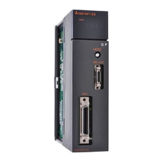
Page 73: Names Of Each Part
4 INSTALLATION, WIRING AND MAINTENANCE OF THE PRODUCT MELSEC-A 4.1.2 Names of each part The names of each AD75 part are shown below. For AD75P3-S3 For A1SD75P3-S3 1SD75P3-S3 D75P3 - S3 1) 17-segment LED MODE 2) Axis display LED RS-422 MODE 3) Mode switch 4) Module version label... - Page 74 Connector for connecting with peripheral device. connector External device connection Connector for connecting drive unit, mechanical system input and manual pulse connector generator. Each AD75 interface is as shown below. AD75P1-S3 AD75P2-S3 AD75P3-S3 A1SD75P1-S3 A1SD75P2-S3 A1SD75P3-S3 MODE MODE MODE RS-422 RS-422 RS-422 RS-422...
-
Page 75: Handling Precautions
4 INSTALLATION, WIRING AND MAINTENANCE OF THE PRODUCT MELSEC-A 4.1.3 Handling precautions Handle the AD75 and cable while observing the following precautions. (1) Handling precautions CAUTION Use the PLC within the general specifications environment given in this manual. Using the PLC outside the general specification range environment could lead to electric shocks, fires, malfunctioning, product damage or deterioration. - Page 76 4 INSTALLATION, WIRING AND MAINTENANCE OF THE PRODUCT MELSEC-A (2) Other precautions (a) Main body • The main body case is made of plastic. Take care not to drop or apply strong impacts onto the case. • Do not remove the AD75 PCB from the case. Failure to observe this could lead to faults.
-
Page 77: Installation
4 INSTALLATION, WIRING AND MAINTENANCE OF THE PRODUCT MELSEC-A 4.2 Installation 4.2.1 Precautions for installation The precautions for installing the AD75 are given below. Refer to this section as well as section "4.1.3 Handling precautions" when carrying out the work. (1) Precautions for installation DANGER Always turn all phases of the power supply OFF externally before cleaning or tightening the... -
Page 78: Wiring
4 INSTALLATION, WIRING AND MAINTENANCE OF THE PRODUCT MELSEC-A 4.3 Wiring The wiring precautions for the AD75 are described below. Be careful to observe the following items together with the “Handling precautions” described in section 4.1.3. 4.3.1 Precautions for wiring Perform wiring of the AD75 correctly while checking the terminal arrangement. - Page 79 4 INSTALLATION, WIRING AND MAINTENANCE OF THE PRODUCT MELSEC-A [Shielding wire processing example] Ground a 2mm or a thicker grounding wire in the shortest path. (Ground to the panel of the AD75 securely.) Strip the sheath of the shielded cable. Remove the shielding wires from the shielded cable and solder them to the grounding cable.
- Page 80 (11) To comply with EMC and low-voltage directives, use shielded cables and AD75CK cable clamp (made by Mitsubishi Electric) to ground to the panel. 1) When using cable of within 2m for wiring •...
- Page 81 4 INSTALLATION, WIRING AND MAINTENANCE OF THE PRODUCT MELSEC-A 4) Cable clamp fitting position and shielded cable grounding method Inside control panel AD75 20 to 30cm AD75CK [How to ground shilded cable using AD75CK] Shielded cable Shielding wires Grounding terminal Grounding terminal installation screw (M4x8 screw) Screw for mounting to control cabinet (M4 screw) AD75CK can ground up to four shielded cables having about 7 mm or smaller outside...
- Page 82 4 INSTALLATION, WIRING AND MAINTENANCE OF THE PRODUCT MELSEC-A (Poor examples and improved examples are shown below.) Wiring duct Relay Relay Drive Drive Relay unit unit Control panel Inverter Changed Wiring duct Relay Relay Relay Control panel Short wiring with the AD75 and drive unit placed in proximity, and the connection cable and Inverter...
-
Page 83: Wiring The External Device Connection Connector Pins
4 INSTALLATION, WIRING AND MAINTENANCE OF THE PRODUCT MELSEC-A 4.3.2 Wiring the external device connection connector pins The pins for the external device connection connector are wired in the following manner..Disassemble the connector section, Disassembling the connector section and remove the connector. - Page 84 4 INSTALLATION, WIRING AND MAINTENANCE OF THE PRODUCT MELSEC-A (2) Connecting the connector and wire * Refer to section "3.5 Specifications of input/output interfaces with external devices" when connecting. (a) Loosen the cable fixture screw B, pass the cable through, and then tighten screw B.
- Page 85 4 INSTALLATION, WIRING AND MAINTENANCE OF THE PRODUCT MELSEC-A (c) After connection, the state will be as shown below. 4 - 15 Artisan Technology Group - Quality Instrumentation ... Guaranteed | (888) 88-SOURCE | www.artisantg.com...
- Page 86 4 INSTALLATION, WIRING AND MAINTENANCE OF THE PRODUCT MELSEC-A (3) Assembling the connector section (a) Fit the soldered connector and cable fixture into the connector cover. * The cable fixture acts as a stopper to protect the signal wire connection section when the cable is pulled on.
-
Page 87: Connecting The Connector
4 INSTALLATION, WIRING AND MAINTENANCE OF THE PRODUCT MELSEC-A 4.3.3 Connecting the connector The AD75 is connected to the drive unit or peripheral device with the connector. Use the following procedure to connect. (1) Connecting (a) Confirm that all phases of the AD75 main unit's power are shut off externally. -
Page 88: Confirming The Installation And Wiring
4 INSTALLATION, WIRING AND MAINTENANCE OF THE PRODUCT MELSEC-A 4.4 Confirming the installation and wiring 4.4.1 Items to confirm when installation and wiring are completed Check the (1) and (2) points when completed with the AD75 installation and wiring. (1) Does the AD75 operate correctly? ... "Single module test" With the "single module test", correct operation of the AD75 is confirmed by the LED displays on the AD75. -
Page 89: Single Module Test
4 INSTALLATION, WIRING AND MAINTENANCE OF THE PRODUCT MELSEC-A 4.4.2 Single module test Whether the AD75 is operating correctly is confirmed with the LED displays on the AD75 main body. The "single module test" methods are described below. The "single module test" can be carried out when there is no sequence program stored in the PLC CPU, when there is no data stored in the AD75, and when the AD75 is running. - Page 90 4 INSTALLATION, WIRING AND MAINTENANCE OF THE PRODUCT MELSEC-A (Step 3) Operation monitor 2 1) The axis display LED for each axis will turn ON sequentially at an approx. 0.5 second interval. One of the following states will appear on the 17-segment LED to indicate the state of the axis for which the axis display LED is ON.
- Page 91 4 INSTALLATION, WIRING AND MAINTENANCE OF THE PRODUCT MELSEC-A (Step 5) Internal information 2 monitor 1) The AD75 OS version will appear on the 17-segment LED for reference. [V000] Version 2) The axis display LED for each axis will turn OFF. 3) When the mode switch is pressed, the state will shift to the input/output information n monitor state described in (Step 6).
- Page 92 4 INSTALLATION, WIRING AND MAINTENANCE OF THE PRODUCT MELSEC-A POINT (1) The operation monitor described in this section is a function that allows the AD75 state, control state of each axis and state of the input/output signals to be confirmed. This monitor can be operated at any time. (2) If the AD75 is not operating correctly, use the operation monitors as necessary.
-
Page 93: Maintenance
4 INSTALLATION, WIRING AND MAINTENANCE OF THE PRODUCT MELSEC-A 4.5 Maintenance 4.5.1 Precautions for maintenance The precautions for servicing the AD75 are given below. Refer to this section as well as section "4.1.3 Handling precautions" when carrying out the work. DANGER Always turn all phases of the power supply OFF externally before cleaning or tightening the screws. - Page 94 4 INSTALLATION, WIRING AND MAINTENANCE OF THE PRODUCT MELSEC-A MEMO 4 - 24 Artisan Technology Group - Quality Instrumentation ... Guaranteed | (888) 88-SOURCE | www.artisantg.com...
- Page 95 Chapter 5 DATA USED FOR POSITIONIG CONTROL The parameters and data used to carry out positioning control with the AD75 are explained in this chapter. With the positioning system using the AD75, the various parameters and data explained in this chapter are used for control. The parameters and data include parameters set according to the device configuration, such as the system configuration, and parameters and data set according to each control.
-
Page 96: Data Used For Positioning Control (List Of Buffer Memory Addresses)
5 DATA USED FOR POSITIONING CONTROL MELSEC-A 5.1 Types of data 5.1.1 Parameters and data required for control The parameters and data required to carry out control with the AD75 include the "setting data", "monitor data" and "control data" shown below. Setting data (Data set beforehand according to the machine and application, and stored in the flash ROM.) Positioning... - Page 97 5 DATA USED FOR POSITIONING CONTROL MELSEC-A Monitor data (Data that indicates the control state. Stored in the buffer memory, and monitors as necessary.) Md.1 Md.56 Monitors the AD75 specifications, such as the module name and OS type, System monitor data and the operation history.
-
Page 98: Setting Items For Positioning Parameters
5 DATA USED FOR POSITIONING CONTROL MELSEC-A 5.1.2 Setting items for positioning parameters The setting items for the "positioning parameters" are shown below. The "positioning parameters" are commonly set for each axis for all control using the AD75. Refer to "SECTION 2" for details on each control, and section "5.2 List of parameters" for details on each setting item. - Page 99 5 DATA USED FOR POSITIONING CONTROL MELSEC-A Manual Main positioning control control Control Position control Other control Positioning parameter – – – Pr.26 Acceleration time 1 – – – Pr.27 Acceleration time 2 – – – Pr.28 Acceleration time 3 12.6.7* –...
-
Page 100: Setting Items For Zero Point Return Parameters
5 DATA USED FOR POSITIONING CONTROL MELSEC-A 5.1.3 Setting items for zero point return parameters When carrying out "zero point return control", the "zero point return parameters" must be set. The setting items for the "zero point return parameters" are shown below. The "zero point return parameters"... -
Page 101: Setting Items For Positioning Data
5 DATA USED FOR POSITIONING CONTROL MELSEC-A 5.1.4 Setting items for positioning data The "positioning data" must be set when carrying out "main positioning control". The setting items for the "positioning data" are shown below. One to 600 "positioning data" items can be set for each axis. Refer to "Chapter 9 MAIN POSITIONING CONTROL"... - Page 102 5 DATA USED FOR POSITIONING CONTROL MELSEC-A Checking the positioning data Da.1 to Da.9 are checked with the following timing. (1) Startup of a positioning operation (2) When the test mode using the AD75 software package 5 - 8 Artisan Technology Group - Quality Instrumentation ... Guaranteed | (888) 88-SOURCE | www.artisantg.com...
-
Page 103: Setting Items For Start Block Data
5 DATA USED FOR POSITIONING CONTROL MELSEC-A 5.1.5 Setting items for start block data The "start block data" must be set when carrying out "advanced positioning control". The setting items for the "start block data" are shown below. Up to 50 points of "start block data" can be set for each axis. Refer to "Chapter 10 ADVANCED POSITIONING CONTROL"... -
Page 104: Setting Items For Condition Data
5 DATA USED FOR POSITIONING CONTROL MELSEC-A 5.1.6 Setting items for condition data When carrying out "advanced positioning control" or using the JUMP command in the "main positioning control", the "condition data" must be set as required. The setting items for the "condition data" are shown below. Up to 10 "condition data"... -
Page 105: Types And Roles Of Monitor Data
5 DATA USED FOR POSITIONING CONTROL MELSEC-A 5.1.7 Types and roles of monitor data Data that indicates the positioning system's operation state is stored in the buffer memory's monitor data area. When using the positioning system, this data must be monitored as necessary. The data that can be monitored is shown below. - Page 106 5 DATA USED FOR POSITIONING CONTROL MELSEC-A Monitoring the positioning system operation history Monitor details Corresponding item Monitor whether the system is in the test mode Md.1 In test mode flag Md.7 Start axis Start axis Md.8 Operation type Operation type Hour : minute Md.9...
- Page 107 5 DATA USED FOR POSITIONING CONTROL MELSEC-A Monitoring the speed Monitor details Corresponding item Indicates the During independent axis control speed of each axis When "0: Indicates the Composite speed" is composite set for " Pr.21 Md.31 Feedrate speed Interpolation speed Monitor the During designation method"...
-
Page 108: Types And Roles Of Control Data
5 DATA USED FOR POSITIONING CONTROL MELSEC-A 5.1.8 Types and roles of control data Several controls are carried out as necessary when using the positioning system. (When the power is turned ON, the default values of the data used for control are set. However, these values can be set with the sequence program when necessary.) The items that can be controlled are shown below. - Page 109 5 DATA USED FOR POSITIONING CONTROL MELSEC-A [Reference] The outline of reading and writing the positioning data is shown below. Reading the positioning data Writing the positioning data (The positioning data stored in the buffer memory Cd.8 (The positioning data designated in the OS memory is is written as the positioning data for the No.
- Page 110 5 DATA USED FOR POSITIONING CONTROL MELSEC-A (2) Controlling the operation Controlling the operation Control details Corresponding item Cd.11 Set which positioning to execute (start No.). Positioning start No. Md.33 Clear (reset) the axis error No. ( ) and axis warning Cd.12 Axis error reset Md.34...
- Page 111 5 DATA USED FOR POSITIONING CONTROL MELSEC-A Making settings related to operation Control details Corresponding item Turn M code ON signal OFF. Cd.14 M code OFF request Cd.15 Set new value when changing current value. New current value Cd.20 Validate speed/position changeover signal from external source. Speed/position changeover enable flag Change movement amount for position control during speed/position Speed/position changeover control...
-
Page 112: List Of Parameters
5 DATA USED FOR POSITIONING CONTROL MELSEC-A 5.2 List of parameters 5.2.1 Basic parameters 1 Setting value buffer Setting value, setting range memory address Default Item value Value set with peripheral Value set with sequence Axis 1 Axis 2 Axis 3 device program 0 : mm... - Page 113 5 DATA USED FOR POSITIONING CONTROL MELSEC-A Pr.2 to Pr.4 Movement amount per pulse Set the movement amount per pulse count when outputting a pulse train from the AD75. The setting is made with Pr.2 to Pr.4 . (The case for the " Pr.1 Unit setting"...
- Page 114 5 DATA USED FOR POSITIONING CONTROL MELSEC-A Pr.3 Movement amount per rotation (Al), Pr.4 Unit magnification (Am) The amount how the workpiece moves with one motor rotation is determined by the mechanical structure. If the worm gear lead (mm/rev) is PB and the deceleration rate is 1/n, then Movement amount per rotation (AL) = PB ×...
- Page 115 5 DATA USED FOR POSITIONING CONTROL MELSEC-A Setting value buffer Setting value, setting range memory address Default Item value Value set with peripheral Value set with sequence Axis 1 Axis 2 Axis 3 device program 0: PULSE/SIGN mode 1: CW/CCW mode 2: A phase/B phase Pr.5 Pulse output mode (multiple of 4)
- Page 116 5 DATA USED FOR POSITIONING CONTROL MELSEC-A (2) CW/CCW mode During forward run, the forward run feed pulse (PULSE F) will be output. During reverse run, the reverse run feed pulse (PULSE R) will be output. Positive logic Negative logic PULSE F PULSE F PULSE R...
- Page 117 5 DATA USED FOR POSITIONING CONTROL MELSEC-A Pr.6 Rotation direction setting Set the relation of the motor rotation direction and current value address increment/decrement. [Setting procedure] 1) Set "0" in Pr.6 , and carry out forward run JOG operation. ("0" is set as the default value for Pr.6 .) 2) When the workpiece "W"...
-
Page 118: Basic Parameters 2
5 DATA USED FOR POSITIONING CONTROL MELSEC-A 5.2.2 Basic parameters 2 Setting value buffer Setting value, setting range memory address Default Item value Value set with peripheral Value set with sequence Axis 1 Axis 2 Axis 3 device program The setting value range differs depending on the " Pr.11 Stepping motor mode selection"... - Page 119 5 DATA USED FOR POSITIONING CONTROL MELSEC-A 1) If the positioning speed setting is slower than the parameter speed limit, the actual acceleration/deceleration time will be relatively short. Thus, set the maximum positioning speed value to be equal to the parameter speed limit value or a close value under the speed limit value.
- Page 120 5 DATA USED FOR POSITIONING CONTROL MELSEC-A Pr.11 Stepping motor mode selection The type of motor controlled with the AD75 is set with the "stepping motor mode selection". 1 : Stepping motor mode ....When using a stepping motor 0 : Standard mode ......When using a different type of motor When carrying out 2-axis interpolation control using both the stepping motor and servomotor, set both axes to "1: Stepping motor mode".
- Page 121 5 DATA USED FOR POSITIONING CONTROL MELSEC-A MEMO 5 - 27 Artisan Technology Group - Quality Instrumentation ... Guaranteed | (888) 88-SOURCE | www.artisantg.com...
-
Page 122: Detailed Parameters 1
5 DATA USED FOR POSITIONING CONTROL MELSEC-A 5.2.3 Detailed parameters 1 Setting value buffer Setting value, setting range memory address Item Default value Value set with Value set with peripheral device Axis 1 Axis 2 Axis 3 sequence program The setting value range differs according to the " Pr.1 Unit setting". - Page 123 5 DATA USED FOR POSITIONING CONTROL MELSEC-A 1) The backlash compensation is valid after completed the machine zero point return. Thus, if the backlash compensation amount is set or changed, always carry out machine zero point return once. 2) The backlash compensation amount setting range is 0 to 65535, but it should be set to 255 or less by using the following expression.
- Page 124 5 DATA USED FOR POSITIONING CONTROL MELSEC-A 1) Generally, the zero point is set at the lower limit or upper limit of the stroke limit. 2) By setting the upper limit value or lower limit value of the software stroke limit, overrun can be prevented in the software.
- Page 125 5 DATA USED FOR POSITIONING CONTROL MELSEC-A Pr.18 Torque limit setting value With this function, the torque generated by the motor is limited to within the set range. * The torque exceeding the limit is reduced to the specified torque limit. Set the maximum torque value necessary for the control in the range between 1 and 500%.
- Page 126 5 DATA USED FOR POSITIONING CONTROL MELSEC-A Pr.19 M code ON signal output timing Set the timing to output the M code ON signal. The WITH mode and AFTER mode can be used for the M code ON signal output timing.
- Page 127 5 DATA USED FOR POSITIONING CONTROL MELSEC-A Setting value buffer Setting value, setting range memory address Default Item value Value set with Value set with peripheral device Axis 1 Axis 2 Axis 3 sequence program 0 : Standard speed changeover mode Pr.20 Speed changeover mode...
- Page 128 5 DATA USED FOR POSITIONING CONTROL MELSEC-A Pr.21 Interpolation speed designation method When carrying out linear interpolation, set whether to designate the composite speed or reference axis speed. 0: Composite speed ....The movement speed for the control target is designated, and the speed for each axis is calculated by the AD75.
- Page 129 5 DATA USED FOR POSITIONING CONTROL MELSEC-A Pr.23 Manual pulse generator selection Set which manual pulse generator to use for control for each axis (motor). 0 : Ignore manual pulse generator operation..Manual pulse generator operation is not carried out. 1 : Use manual pulse generator 1.......
-
Page 130: Detailed Parameters 2
5 DATA USED FOR POSITIONING CONTROL MELSEC-A 5.2.4 Detailed parameters 2 Setting value buffer Setting value, setting range memory address Default Item value Value set with Value set with peripheral device Axis 1 Axis 2 Axis 3 sequence program Pr.26 Acceleration time 1 Pr.27 Acceleration time 2 The setting value range differs according to the "... - Page 131 5 DATA USED FOR POSITIONING CONTROL MELSEC-A [Table 1] Pr.25 Value set with peripheral device Value set with sequence program (ms) (ms) setting value 0 : 1-word type 1 to 65535 1 to 65535* 1 : 2-word type 1 to 8388608 1 to 8388608 * 1 to 32767 : Set as a decimal...
- Page 132 5 DATA USED FOR POSITIONING CONTROL MELSEC-A Setting value buffer Setting value, setting range memory address Default Item value Value set with Value set with peripheral device Axis 1 Axis 2 Axis 3 sequence program 0 : Automatic trapezoid Pr.35 Acceleration/decel- acceleration/deceleration process eration process 1 : S-pattern...
- Page 133 5 DATA USED FOR POSITIONING CONTROL MELSEC-A Pr.36 S-pattern proportion Set the S-pattern ratio (1 to 100%) for carrying out the S-pattern acceleration/deceleration process. The S-pattern ratio indicates where to draw the acceleration/deceleration curve using the Sin curve as shown below. (Example) Positioning speed...
- Page 134 5 DATA USED FOR POSITIONING CONTROL MELSEC-A Pr.37 Sudden stop deceleration time Set the time to reach speed 0 from " Pr.7 Speed limit value" during the sudden stop. The setting value size is determined by " Pr.25 Size selection for acceleration/deceleration time".
- Page 135 5 DATA USED FOR POSITIONING CONTROL MELSEC-A Pr.38 Stop group 1 sudden stop selection Pr.40 Stop group 3 sudden stop selection Set the method to stop when the stop causes in the following stop groups occur. • Stop group 1 ....Stop with hardware stroke limit •...
- Page 136 5 DATA USED FOR POSITIONING CONTROL MELSEC-A Setting value buffer Setting value, setting range memory address Default Item value Value set with peripheral Value set with sequence Axis 1 Axis 2 Axis 3 device program 0 to 65535 (ms) 0 to 32767 : Pr.41 Positioning Complete Set as a decimal 0 to 65535 (ms)
- Page 137 5 DATA USED FOR POSITIONING CONTROL MELSEC-A [Table 1] Pr.11 Pr.1 Value set with peripheral device Value set with sequence program (unit) (unit) setting value setting value 0 to 100000 ( × 10 µ m) 0 to 10000.0 ( µ m) 0 : mm 0 to 100000 ( ×...
- Page 138 5 DATA USED FOR POSITIONING CONTROL MELSEC-A Pr.43 External start function selection Set which function to use the external start signal with. 0 : External positioning start ....Carry out positioning operation with external start signal input. 1 : External speed change request ..Change the speed of the positioning operation currently being executed with the external start signal input.
-
Page 139: Zero Point Return Basic Parameters
5 DATA USED FOR POSITIONING CONTROL MELSEC-A 5.2.5 Zero point return basic parameters Setting value buffer Setting value, setting range memory address Default Item value Value set with peripheral Value set with sequence Axis 1 Axis 2 Axis 3 device program 0 : Near-point dog method 1 : Stopper stop method 1) - Page 140 5 DATA USED FOR POSITIONING CONTROL MELSEC-A 1 : Stopper stop method 1) (1) Start machine zero point return. (Start movement at the " Pr.48 Zero point return speed" in Pr.48 Zero point return speed the " Pr.46 Zero point return direction".) (2) Detect the near-point dog ON, and start deceleration.
- Page 141 5 DATA USED FOR POSITIONING CONTROL MELSEC-A 4 : Count method 1) (1) Start machine zero point return. (Start movement at the " Pr.48 Zero point return speed" in Pr.52 Zero point Pr.48 Setting for the movement the " Pr.46 Zero point return direction".) return speed amount after near-poing dog ON (2) Detect the near-point dog ON, and start deceleration.
- Page 142 5 DATA USED FOR POSITIONING CONTROL MELSEC-A Setting value buffer Setting value, setting range memory address Default Item value Value set with sequence Value set with peripheral device Axis 1 Axis 2 Axis 3 program 0 : Positive direction (address increment direction) Pr.46 Zero point return direction...
- Page 143 5 DATA USED FOR POSITIONING CONTROL MELSEC-A [Table 1] Pr.11 Pr.1 Value set with peripheral device Value set with sequence program (unit) (unit) setting value setting value –214748364.8 to 214748364.7 ( µ m) –2147483648 to 2147483647 ( × 10 µ m) 0 : mm –21474.83648 to 21474.83647 (inch) –2147483648 to 2147483647 ( ×...
- Page 144 5 DATA USED FOR POSITIONING CONTROL MELSEC-A Setting value buffer Setting value, setting range memory address Default Item value Value set with peripheral Value set with sequence Axis 1 Axis 2 Axis 3 device program The setting value range differs depending on the " Pr.11 Stepping motor mode selection"...
- Page 145 5 DATA USED FOR POSITIONING CONTROL MELSEC-A [Table 1] Pr.11 Pr.1 Value set with peripheral device Value set with sequence program setting value setting value (unit) (unit) 1 to 600000000 ( × 10 0 : mm 0.01 to 6000000.00 (mm/min) mm/min) 1 to 600000000 ( ×...
-
Page 146: Zero Point Return Detailed Parameters
5 DATA USED FOR POSITIONING CONTROL MELSEC-A 5.2.6 Zero point return detailed parameters Setting value buffer Setting value, setting range memory address Default Item value Value set with Value set with peripheral device Axis 1 Axis 2 Axis 3 sequence program 0 to 65535 (ms) 0 to 32767 : Pr.51 Zero point return... - Page 147 5 DATA USED FOR POSITIONING CONTROL MELSEC-A [Table 1] Pr.11 Pr.1 Value set with peripheral device Value set with sequence program (unit) (unit) setting value setting value 0 to 2147483647 ( × 10 µ m) 0 to 214748364.7 ( µ m) 0 : mm 0 to 2147483647 ( ×...
- Page 148 5 DATA USED FOR POSITIONING CONTROL MELSEC-A Setting value buffer Setting value, setting range memory address Default Item value Value set with peripheral Value set with sequence Axis 1 Axis 2 Axis 3 device program The setting value range differs depending on the " Pr.11 Stepping motor mode selection"...
- Page 149 5 DATA USED FOR POSITIONING CONTROL MELSEC-A [Table 1] Pr.11 Pr.1 Value set with peripheral device Value set with sequence program (unit) (unit) setting value setting value –2147483648 to 2147483647 ( × 10 µ m) –214748364.8 to 214748364.7 ( µ m) 0 : mm –2147483648 to 2147483647 ( ×...
-
Page 150: List Of Positioning Data
5 DATA USED FOR POSITIONING CONTROL MELSEC-A 5.3 List of positioning data Before explaining the positioning data setting items Da.1 to Da.9 , the configuration of the positioning data will be shown below. The positioning data stored in the AD75 buffer memory has the following type of configuration. - Page 151 5 DATA USED FOR POSITIONING CONTROL MELSEC-A 4290 4280 Positioning data No. Positioning identifier 3320 3310 4291 3300 4281 Da.1 Da.4 3321 Da.9 3311 4292 3301 4282 M code 3322 Da.8 4294 3312 4284 3302 4295 Dwell time 4285 3324 3314 4296 Da.7...
- Page 152 5 DATA USED FOR POSITIONING CONTROL MELSEC-A Setting value buffer Default Setting value Item memory address value Value set with peripheral device Value set with sequence program Axis 1 Axis 2 Axis 3 00 : Positioning complete Operation pattern Da.1 Operation 01 : Continuous positioning control pattern...
- Page 153 5 DATA USED FOR POSITIONING CONTROL MELSEC-A Da.1 Operation pattern The operation pattern designates whether positioning of a certain data No. is to be ended with just that data, or whether the positioning for the next data No. is to be carried out in succession.
- Page 154 5 DATA USED FOR POSITIONING CONTROL MELSEC-A Setting value buffer Setting value, setting range memory address Default Item value Value set with peripheral Value set with sequence Axis 1 Axis 2 Axis 3 device program The setting value range differs according to the " Da.2 Control method".
- Page 155 5 DATA USED FOR POSITIONING CONTROL MELSEC-A [Table 1] When " Pr.1 Unit setting" is "mm" Value set with sequence program * Value set with peripheral device Da.2 ( µ m) ( × 10 µ m) setting value ◊ Set the address ◊...
- Page 156 5 DATA USED FOR POSITIONING CONTROL MELSEC-A When " Pr.1 Unit setting" is "degree" Value set with sequence program * Da.2 Value set with peripheral device ( × 10 setting value (degree) degree) ◊ Set the address ◊ Set the address ABS Linear 1 : 01 0 to 359.99999 *...
- Page 157 5 DATA USED FOR POSITIONING CONTROL MELSEC-A When " Pr.1 Unit setting" is "inch" Value set with sequence program * Da.2 Value set with peripheral device ( × 10 setting value (inch) inch) ◊ Set the address ◊ Set the address ABS Linear 1 : 01 –21474.83648 to 21474.83647 *...
- Page 158 5 DATA USED FOR POSITIONING CONTROL MELSEC-A Setting value buffer Setting value, setting range memory address Default Item value Value set with peripheral Value set with sequence Axis 1 Axis 2 Axis 3 device program The setting value range differs according to the " Da.2 Control method".
- Page 159 5 DATA USED FOR POSITIONING CONTROL MELSEC-A [Table 1] When " Pr.1 Unit setting" is "mm" Value set with sequence program * Value set with peripheral device Da.2 ( µ m) ( × 10 µ m) setting value ABS Circular interpolation : 07 ◊...
- Page 160 5 DATA USED FOR POSITIONING CONTROL MELSEC-A When " Pr.1 Unit setting" is "pulse" Value set with sequence program * Da.2 Value set with peripheral device setting value (pulse) ( pulse ) ABS Circular interpolation : 07 ◊ Set the address ◊...
- Page 161 5 DATA USED FOR POSITIONING CONTROL MELSEC-A When " Pr.1 Unit setting" is "inch" Value set with sequence program * Da.2 Value set with peripheral device ( × 10 setting value (inch) inch ) ABS Circular interpolation : 07 ◊ Set the address ◊...
- Page 162 5 DATA USED FOR POSITIONING CONTROL MELSEC-A Setting value buffer Setting value, setting range memory address Default Item value Value set with peripheral Value set with sequence Axis 1 Axis 2 Axis 3 device program The setting value range differs depending on the " Pr.11 Stepping motor mode selection"...
- Page 163 5 DATA USED FOR POSITIONING CONTROL MELSEC-A [Table 1] Pr.11 Pr.1 Value set with sequence program Value set with peripheral device (unit) (unit) setting value setting value 1 to 600000000 ( × 10 0 : mm 0.01 to 6000000.00 (mm/min) mm/min) 1 to 600000000 ( ×...
- Page 164 5 DATA USED FOR POSITIONING CONTROL MELSEC-A Da.8 Dwell time/JUMP designation positioning data No. Set the "dwell time" or "positioning data No." corresponding to the " Da.2 Control method". • When a method other than "JUMP command" is set for " Da.2 Control method" ..
-
Page 165: List Of Start Block Data
5 DATA USED FOR POSITIONING CONTROL MELSEC-A 5.4 List of start block data Before explaining the start block data setting items Da.1 to Da.13 , the configuration of the start block data will be shown below. The start block data stored in the AD75 buffer memory has the following type of configuration. - Page 166 5 DATA USED FOR POSITIONING CONTROL MELSEC-A 50th point Buffer memory Setting item address 2nd point 1st point Buffer memory Setting item ddress 4849 Buffer memory Setting item address 4801 4800 Da.11 4899 Da.10 Start data No. Shape 4851 4850 Da.12 Da.13 Special start...
- Page 167 5 DATA USED FOR POSITIONING CONTROL MELSEC-A Setting value buffer Setting value memory address Default Item value Value set with peripheral Value set with sequence program Axis 1 Axis 2 Axis 3 device 0 : End Da.10 Shape 0 0 0 1 : Continue 0000 4300 4550 4800...
- Page 168 5 DATA USED FOR POSITIONING CONTROL MELSEC-A Da.10 Shape Set whether to carry out only the local "start block data" and then end control, or to execute the "start block data" set in the next point. Setting value Setting details 0 : End Execute the designated point's "start block data", and then complete the control.
-
Page 169: List Of Condition Data
5 DATA USED FOR POSITIONING CONTROL MELSEC-A 5.5 List of condition data Before explaining the condition data setting items Da.14 to Da.18 , the configuration of the condition data will be shown below. The condition data stored in the AD75 buffer memory has the following type of configuration. - Page 170 5 DATA USED FOR POSITIONING CONTROL MELSEC-A 10th item Buffer memory Setting item address 2nd item 1st item Buffer memory Setting item ddress 4990 Buffer memory Setting item address 4910 4991 4900 4992 4993 Da.15 Da.14 4994 4911 Condition operator Condition target 4995 4912...
- Page 171 5 DATA USED FOR POSITIONING CONTROL MELSEC-A Setting value buffer Setting value memory address Default Item value Value set with peripheral Value set with sequence program Axis 1 Axis 2 Axis 3 device 01 : Device X 02 : Device Y Da.14 Condition target 03 : Buffer memory (1-word)
- Page 172 5 DATA USED FOR POSITIONING CONTROL MELSEC-A Da.14 Condition target Set the condition target as required for each control. Setting value Setting details : Device X Set the input/output signal ON/OFF as the conditions. : Device Y : Buffer memory (1-word) Set the value stored in the buffer memory as the condition.
- Page 173 5 DATA USED FOR POSITIONING CONTROL MELSEC-A Da.17 Parameter 1 Set the parameters as required for the " Da.15 Condition operator". Da.15 Condition operator Setting value Setting details : ∗∗=P1 Value Set the "P1" value. : ∗∗≤P1, P2≤∗∗ : DEV=ON Value Set the device's bit No.
-
Page 174: List Of Monitor Data
5 DATA USED FOR POSITIONING CONTROL MELSEC-A 5.6 List of monitor data 5.6.1 System monitor data Storage item Storage details Whether the mode is the test mode from the peripheral device or not is stored. • Md.1 In test mode flag When not in test mode : OFF •... - Page 175 0: Not in test mode 1: In test mode Monitoring is carried out with a decimal. – Monitor Storage value value (Corresponding 0: A1SD75P1-S3/AD75P1-S3 name) 1: A1SD75P2-S3/AD75P2-S3 2: A1SD75P3-S3/AD75P3-S3 Monitoring is carried out with a Monitor value hexadecimal. Example) When name is "AD75"...
- Page 176 5 DATA USED FOR POSITIONING CONTROL MELSEC-A Storage item Storage details Reading the monitor value Monitoring is carried out with a decimal. Monitor Md.7 The No. of the axis that started is Storage value value stored. 1: Axis 1 Start axis 2: Axis 2 3: Axis 3 [Stored contents]...
- Page 177 5 DATA USED FOR POSITIONING CONTROL MELSEC-A Default value Storage buffer memory address (common for axis 1 to axis 3) Md.12 Starting history pointer The pointer No. following the pointer No. where the latest start history is stored is stored. 0000 Pointer No.
- Page 178 5 DATA USED FOR POSITIONING CONTROL MELSEC-A Storage item Storage details Reading the monitor value Monitoring is carried out with a decimal. The No. of the axis for which an Monitor Md.13 Storage value value error was detected when starting 1: Axis 1 Start axis is stored.
- Page 179 5 DATA USED FOR POSITIONING CONTROL MELSEC-A Default value Storage buffer memory address (common for axis 1 to axis 3) Md.18 Starting history pointer at error The pointer No. following the pointer No. where the latest start history during errors is stored is stored. 0000 Pointer No.
- Page 180 5 DATA USED FOR POSITIONING CONTROL MELSEC-A Storage item Storage details Reading the monitor value Monitoring is carried out with a decimal. Md.19 Monitor The axis No. for which an Storage value value Axis in which the 1: Axis 1 error was detected is stored.
- Page 181 5 DATA USED FOR POSITIONING CONTROL MELSEC-A Default value Storage buffer memory address (common for axis 1 to axis 3) Md.23 Error history pointer The pointer No. following the pointer No. where the latest error history is stored is stored. Pointer No.
- Page 182 5 DATA USED FOR POSITIONING CONTROL MELSEC-A Storage item Storage details Reading the monitor value Monitoring is carried out with a decimal. Md.24 The axis No. for which a Monitor Storage value Axis in which the value warning was detected is 1: Axis 1 warning stored.
- Page 183 5 DATA USED FOR POSITIONING CONTROL MELSEC-A Default value Storage buffer memory address (common for axis 1 to axis 3) Md.28 Warning history pointer The pointer No. following the pointer No. where the latest warning history is stored is stored. Pointer No.
-
Page 184: Axis Monitor Data
5 DATA USED FOR POSITIONING CONTROL MELSEC-A 5.6.2 Axis monitor data Storage item Storage details The currently commanded address is stored. (Different from the actual motor position during operation) The current position address is stored. • Update timing : 56.8ms Md.29 Current feed value •... - Page 185 5 DATA USED FOR POSITIONING CONTROL MELSEC-A Storage buffer memory address Reading the monitor value Default value Axis 1 Axis 2 Axis 3 Monitoring is carried out with a hexadecimal. Low-order buffer memory Example) 800 Monitor value 1000 0000 1001 High-order buffer memory Example) 801 ◊...
- Page 186 5 DATA USED FOR POSITIONING CONTROL MELSEC-A Storage item Storage details When an axis warning is detected, the warning code corresponding to the details of the warning is stored. • The latest warning code is always stored. (When a new axis warning occurs, Md.34 Axis warning No.
- Page 187 5 DATA USED FOR POSITIONING CONTROL MELSEC-A Storage buffer memory address Reading the monitor value Default value Axis 1 Axis 2 Axis 3 Monitoring is carried out with a decimal. Monitor Warning No. value 1008 Refer to section "14.3 List of warnings"...
- Page 188 5 DATA USED FOR POSITIONING CONTROL MELSEC-A Storage item Storage details • The speed commanded by the AD75 to each axis is stored. (May differ from the actual motor speed.) Md.37 Axis feedrate • “0” is stored when the axis is stopped. •...
- Page 189 5 DATA USED FOR POSITIONING CONTROL MELSEC-A Storage buffer memory address Reading the monitor value Default value Axis 1 Axis 2 Axis 3 Monitoring is carried out with a hexadecimal. Low-order buffer memory Example) 812 Monitor value High-order buffer memory Example) 813 1012 0000 1013...
- Page 190 5 DATA USED FOR POSITIONING CONTROL MELSEC-A Storage item Storage details The ON/OFF state of each flag is stored. The following items are stored. In speed control flag : This signal is used to judge whether the system is in speed control or position control.
- Page 191 5 DATA USED FOR POSITIONING CONTROL MELSEC-A Storage buffer memory address Reading the monitor value Default value Axis 1 Axis 2 Axis 3 Monitoring is carried out with a hexadecimal. Monitor value Buffer 0 0 0 0 0 0 0 0 0 0 0 0 0 0 0 0 memory Not used Not used...
- Page 192 5 DATA USED FOR POSITIONING CONTROL MELSEC-A Storage item Storage details • During operation with positioning data : The actual target speed, considering the override and speed limit value, etc., is stored. "0" is stored when positioning is completed. • During interpolation : The composite speed or reference axis speed is stored in the reference...
- Page 193 5 DATA USED FOR POSITIONING CONTROL MELSEC-A Storage buffer memory address Reading the monitor value Default value Axis 1 Axis 2 Axis 3 Monitoring is carried out with a hexadecimal display. Low-order buffer memory Example) 820 1020 Monitor 0000 1021 value High-order buffer memory Example) 821 ◊...
- Page 194 5 DATA USED FOR POSITIONING CONTROL MELSEC-A Storage item Storage details • Md.46 Special start data command The "command code" used with special start and indicated by the start data code setting value pointer currently being executed is stored. The "command parameter" used with special start and indicated by the start data Md.47 Special start data command pointer currently being executed is stored.
- Page 195 5 DATA USED FOR POSITIONING CONTROL MELSEC-A Storage buffer memory address Reading the monitor value Default value Axis 1 Axis 2 Axis 3 Monitoring is carried out with a decimal display. Monitor Storage value value 00: Block start (Normal start) 01: Condition start 02: Wait start 1027...
- Page 196 5 DATA USED FOR POSITIONING CONTROL MELSEC-A Storage item Storage details • The point No. (1 to 50) of the start data currently being executed is stored. Md.51 Start data pointer being • executed "0" is stored when positioning is completed. •...
- Page 197 5 DATA USED FOR POSITIONING CONTROL MELSEC-A Storage buffer memory address Reading the monitor value Default value Axis 1 Axis 2 Axis 3 Monitoring is carried out with a decimal display. Monitor Storage value 1032 value 1 to 50 Monitoring is carried out with a decimal display. Monitor Storage value 1033...
-
Page 198: List Of Control Data
5 DATA USED FOR POSITIONING CONTROL MELSEC-A 5.7 List of control data 5.7.1 System control data Setting item Setting details • The clock data (hour) from the PLC CPU is set after the AD75 power is turned Cd.1 Clock data setting (hour) •... - Page 199 5 DATA USED FOR POSITIONING CONTROL MELSEC-A Storage buffer memory address Setting value Default value (common for axis 1 to axis 3) Set with a BCD code. 00 to 23 (hour) Setting value 0000 1100 Buffer memory 0 0 0 0 0 0 0 0 0 0 0 0 0 0 0 No setting 0 to 2 0 to 3...
- Page 200 5 DATA USED FOR POSITIONING CONTROL MELSEC-A Setting item Setting details • Cd.5 Positioning data No. Set the positioning data No. targeted for reading or writing. • When writing the positioning data stored in the Cd.8 data storage address into the positioning data designated with Cd.5 , set the type of the data targeted for writing.
- Page 201 5 DATA USED FOR POSITIONING CONTROL MELSEC-A Storage buffer memory address Setting value Default value (common for axis 1 to axis 3) Set with a decimal. Setting value 1104 Positioning data 1 to 600 Set with a hexadecimal. Setting value Buffer 0 0 0 0 0 0 0 0 0 0 0 0 0 0 0 0 memory...
- Page 202 5 DATA USED FOR POSITIONING CONTROL MELSEC-A Setting item Setting details Cd.8 Read/write positioning data • Store the data when reading or writing. • Cd.9 Flash ROM write request Write the OS memory contents into the flash ROM. • Set whether the setting data will be initialized or not. Initialization: Indicates that the setting values of the setting data are returned to the default values.
- Page 203 5 DATA USED FOR POSITIONING CONTROL MELSEC-A Storage buffer memory address Setting value Default value (common for axis 1 to axis 3) Each stored item is stored in the following storage address. Storage address Stored item Reference Axis 1 Axis 2 Axis 3 1108 1118 1128 Positioning identifier Da.1...
-
Page 204: Axis Control Data
5 DATA USED FOR POSITIONING CONTROL MELSEC-A 5.7.2 Axis control data Setting item Setting details • Cd.11 Positioning start No. Set the positioning start No. • Clears the axis error detection, axis error No., axis warning detection and axis warning No. Cd.12 Axis error reset •... - Page 205 5 DATA USED FOR POSITIONING CONTROL MELSEC-A Storage buffer memory address Setting value Default value Axis 1 Axis 2 Axis 3 Set with a decimal. Setting value 1150 1200 1250 Positioning data No. · 1 to 600 : Positioning data No. ·...
- Page 206 5 DATA USED FOR POSITIONING CONTROL MELSEC-A Setting item Setting details • When changing the current feed value using the start No. "9003", set the new current feed value. • The value is set within the following range. Pr.1 inch degree pulse µ...
- Page 207 5 DATA USED FOR POSITIONING CONTROL MELSEC-A Storage buffer memory address Setting value Default value Axis 1 Axis 2 Axis 3 Set with a decimal. Actual New current value Cd.15 value 1154 1204 1254 New speed value Cd.16 1155 1205 1255 ◊...
- Page 208 5 DATA USED FOR POSITIONING CONTROL MELSEC-A Setting item Setting details • Set the JOG speed for JOG operation. • The value is set within the following range. inch degree Pr.1 pulse (×10 (×10 (×10 mm/min) (pulse/s) Pr.11 inch/min) degree/min) Cd.19 JOG speed Standard 0 to...
- Page 209 5 DATA USED FOR POSITIONING CONTROL MELSEC-A Storage buffer memory address Setting value Default value Axis 1 Axis 2 Axis 3 Set with a decimal. Actual JOG speed Cd.19 value ◊ Integer value Unit conversion table × 10 Cd.19 1160 1210 1260 Unit...
- Page 210 5 DATA USED FOR POSITIONING CONTROL MELSEC-A Setting item Setting details Cd.22 Manual pulse generator • Set whether or not to carry out manual pulse generator operation. enable flag • Set the magnification of the No. of pulses input from the manual pulse generator. Cd.23 Manual pulse generator 1 •...
- Page 211 5 DATA USED FOR POSITIONING CONTROL MELSEC-A Storage buffer memory address Setting value Default value Axis 1 Axis 2 Axis 3 Set with a decimal. Setting value 1167 1217 1267 Manual pulse generator enable flag 0: Disable manual pulse generator operation 1: Enable manual pulse generator operation Set with a decimal.
- Page 212 5 DATA USED FOR POSITIONING CONTROL MELSEC-A Setting item Setting details • Cd.27 Step mode When using step operation, set which unit to step with. • Cd.28 Step start information When using step operation, set whether to continue or restart operation. •...
- Page 213 5 DATA USED FOR POSITIONING CONTROL MELSEC-A Storage buffer memory address Setting value Default value Axis 1 Axis 2 Axis 3 Set with a decimal. Setting value 1173 1223 1273 Step mode 0: Carry out step operation with deceleration unit 1: Carry out step operation with data No.
- Page 214 5 DATA USED FOR POSITIONING CONTROL MELSEC-A Setting item Setting details • To interrupt the operation during continuous operation, set "1". Cd.32 Interrupt request during • If the interrupt request is received after setting "1", "0" will be automatically stored continuous operation by the OS.
- Page 215 5 DATA USED FOR POSITIONING CONTROL MELSEC-A Storage buffer memory address Setting value Default value Axis 1 Axis 2 Axis 3 Set with a decimal. Setting value 1181 1231 1281 Continuous operation interrupt request 1: Interrupt continuous control or continuous path control.
- Page 216 5 DATA USED FOR POSITIONING CONTROL MELSEC-A MEMO 5 - 122 Artisan Technology Group - Quality Instrumentation ... Guaranteed | (888) 88-SOURCE | www.artisantg.com...
-
Page 217: Sequence Program Used For Positioning Control
Chapter 6 SEQUENCE PROGRAM USED FOR POSITIONING CONTROL The programs required to carry out positioning control with the AD75 are explained in this chapter. The sequence program required for control is created allowing for the "start conditions", "start time chart", "device settings" and general control configuration. (The parameters, positioning data, start block data and condition data, etc., must be set in the AD75 according to the control to be executed, and program for setting the control data or a program for starting the various control must be created.) -
Page 218: Precautions For Creating Program
6 SEQUENCE PROGRAM USED FOR POSITIONINGCONTROL MELSEC-A 6.1 Precautions for creating program The common precautions to be taken when writing data from the PLC CPU to the AD75 buffer memory are described below. (1) Reading/writing the data Setting the data explained in this chapter (various parameters, positioning data, positioning start information) should be set using the AD75 software package. - Page 219 Circular S-pattern Speed/position changeover Control other interpolation acceleration/ control (CHG input than that on left control deceleration simultaneously for two axes) A1SD75P1-S3 10 times/axis 10 times/axis 10 times/axis 10 times/axis AD75P1-S3 A1SD75P2-S3 10 times/axis 10 times/axis 10 times/axis 10 times/axis...
-
Page 220: List Of Devices Used
6 SEQUENCE PROGRAM USED FOR POSITIONINGCONTROL MELSEC-A 6.2 List of devices used The application of the input/output Nos. [X] [Y], internal relays [M] and data registers [D] used in this chapter are shown below. Device Device Application Details when ON name Axis 1 Axis 2 Axis 3 AD75 READY signal... - Page 221 6 SEQUENCE PROGRAM USED FOR POSITIONINGCONTROL MELSEC-A Device Device Application Details when ON name Axis 1 Axis 2 Axis 3 Acceleration/deceleration time change Commanding acceleration/deceleration disable command time change disable Torque change command Commanding torque change Step operation command Commanding step operation –...
- Page 222 6 SEQUENCE PROGRAM USED FOR POSITIONINGCONTROL MELSEC-A Device Device Application Details when ON name Axis 1 Axis 2 Axis 3 Parameter initialization command pulse Parameter initialization commanded Parameter initialization command storage Parameter initialization command held Flash ROM write command pulse Flash ROM write commanded Flash ROM write command storage Flash ROM write command held...
- Page 223 6 SEQUENCE PROGRAM USED FOR POSITIONINGCONTROL MELSEC-A Device Device Application Details when ON name Axis 1 Axis 2 Axis 3 Read/write request ( Cd.7 Read/write request) Teaching results ( Cd.7 Read/write request) Axis state ( Md.35 Axis operation status) Restart request ( Cd.13 Restart command) Parameter initialization results ( Cd.10 Parameter initialization request)
-
Page 224: Creating A Program
6 SEQUENCE PROGRAM USED FOR POSITIONING CONTROL MELSEC-A 6.3 Creating a program The "positioning control operation program" actually used is explained in this chapter. The functions and programs explained in "SECTION 2" are assembled into the "positioning control operation program" explained here. (To monitor the control, add the required monitor program that matches the system. -
Page 225: Positioning Control Operation Program
6 SEQUENCE PROGRAM USED FOR POSITIONING CONTROL MELSEC-A 6.3.2 Positioning control operation program The various programs that configure the "positioning control operation program" are shown below. When creating the program, refer to the explanation of each program and section "6.4 Positioning program examples", and create an operation program that matches the positioning system. - Page 226 6 SEQUENCE PROGRAM USED FOR POSITIONING CONTROL MELSEC-A Continued from previous page Start details setting program * Program required to carry out • "Zero point return control" • "Main positioning control" No.8 • "Advance d positioning control" Positioning start No. Refer to section 6.5.2 setting program Start program...
- Page 227 6 SEQUENCE PROGRAM USED FOR POSITIONING CONTROL MELSEC-A Continued from previous page Auxiliary program * Program added according to control details. (Create as required.) No.13 Speed change program Refer to section 12.5.1 No.14 Override program Refer to section 12.5.2 No.15 Acceleration/deceleration time Refer to section 12.5.3 change program...
-
Page 228: Positioning Program Examples
6 SEQUENCE PROGRAM USED FOR POSITIONING CONTROL MELSEC-A 6.4 Positioning program examples An example of the "Axis 1" positioning program is given in this section. [No. 1] to [No. 3] parameter and data setting program * When setting the parameters or data with the sequence program, set them in the AD75 using the TO command from the PLC CPU. - Page 229 6 SEQUENCE PROGRAM USED FOR POSITIONING CONTROL MELSEC-A No.3 Positionig start information setting program Start block data of block No.7000 (axis 1) For setting of points 1 to 5 (Conditions) Shapes: Continued at points 1 to 4, ended at point 5 Special start command : Normal start at all of points 1 to 5 <Positioning data are already preset>...
- Page 230 6 SEQUENCE PROGRAM USED FOR POSITIONING CONTROL MELSEC-A No.5 External start function valid setting program <External start valid write> <External start invalid write> No.6 Clock data setting program <CPU clock data read command ON> <Clock data write command ON> <Date, hour, minute second data transmission> <Clock data writing set>...
- Page 231 6 SEQUENCE PROGRAM USED FOR POSITIONING CONTROL MELSEC-A (3) Positioning with positioning data No.1 (Control other than speed/position changeover control) <Positioning data No.1 setting> <Positioning data No. write> (4) Positioning with positioning data No.1 (Speed/position changeover control) <Positioning data No.1 setting> <Positioning data No.1 write>...
- Page 232 6 SEQUENCE PROGRAM USED FOR POSITIONING CONTROL MELSEC-A No.10 Reset program <Positioning start signal OFF> <M code OFF request write> No.11 JOG operation program <JOG operation speed setting> <JOG operation speed write> <In JOG flag ON> <JOG operation completed> <Forward run JOG operation execution> <Reverse run JOG operation execution>...
- Page 233 6 SEQUENCE PROGRAM USED FOR POSITIONING CONTROL MELSEC-A No.13 Speed change program <Speed change command pulse> <Speed change command hold> <New speed value setting> <Speed change request setting> <Speed change write> <Speed change result read> <Speed change command storage OFF> No.14 Override program <Override command pulse>...
- Page 234 6 SEQUENCE PROGRAM USED FOR POSITIONING CONTROL MELSEC-A No.17 Step operation program <Step operation command pulse> <Step operation run selection> <Data No. unit step mode selection> <Step operation command write> No.18 Skip program <Skip operation command pulse> <Skip operation command ON storage> <Skip operation command write>...
- Page 235 6 SEQUENCE PROGRAM USED FOR POSITIONING CONTROL MELSEC-A No.20 Continuous operation interrupt program <Continuous operation interrupt command pulse> <Continuous operation interrupt write> No.21 Restart program <Restart command pulse> <Axis status read> <Restart command ON during stop> <Restart request write> <Restart complete read> <Restart command storage OFF>...
- Page 236 6 SEQUENCE PROGRAM USED FOR POSITIONING CONTROL MELSEC-A No.24 Error reset program <Error code read> <Error code read complete confirmation> <Error reset command pulse> <Error reset execution> <Error code read complete OFF> No.25 Stop program <Stop command pulse> <Stop execution> <Axis stop signal OFF due to axis stop>...
-
Page 237: Program Details
6 SEQUENCE PROGRAM USED FOR POSITIONING CONTROL MELSEC-A 6.5 Program details 6.5.1 Initialization program (1) Zero point return request OFF program This program forcibly turns OFF the "zero point return request flag" ( Md.40 Status signal: b3) which is ON. When using a system that does not require zero point return, assemble the program to cancel the "zero point return request"... -
Page 238: Start Details Setting Program
6 SEQUENCE PROGRAM USED FOR POSITIONING CONTROL MELSEC-A 6.5.2 Start details setting program This program sets which control, out of "zero point control", "main positioning control" or "advanced positioning control" to execute. For "advanced positioning control", "high- speed zero point return" and "speed/position changeover control", add the respectively required sequence program. -
Page 239: Start Program
6 SEQUENCE PROGRAM USED FOR POSITIONING CONTROL MELSEC-A 6.5.3 Start program This program is used to start the control with start commands. The control can be started with the following two methods. (1) Starting by inputting positioning start signal [Y10, Y11, Y12] (2) Starting by inputting external start signal Buffer memory Drive unit... - Page 240 6 SEQUENCE PROGRAM USED FOR POSITIONING CONTROL MELSEC-A (1) Starting by inputting positioning start signal Operation when starting (1) When the positioning start signal turns ON, the start complete signal and BUSY signal turn ON, and the positioning operation starts. It can be seen that the axis is operating when the BUSY signal is ON.
- Page 241 6 SEQUENCE PROGRAM USED FOR POSITIONING CONTROL MELSEC-A Starting time chart The time chart for starting each control is shown below. (1) Time chart for starting "machine zero point return" Near-point dog Zero point signal Positioning start signal [Y10] PLC READY signal [Y1D] AD75 READY signal [X0]...
- Page 242 6 SEQUENCE PROGRAM USED FOR POSITIONING CONTROL MELSEC-A Time chart for starting "high-speed zero point return" Positioning start signal [Y10] [Y1D] PLC READY signal AD75 READY signal [X0] Start complete signal [X1] [X4] BUSY signal Error detection signal [XA] 9002 Cd.11 Positioning start No.
- Page 243 6 SEQUENCE PROGRAM USED FOR POSITIONING CONTROL MELSEC-A Time chart for starting "main positioning control" Operation pattern Dwell time Positioning data No. 1(11) 2(00) Positioning start signal [Y10] [Y1D] PLC READY signal AD75 READY signal [X0] Start complete signal [X1] BUSY signal [X4] Positioning complete signal...
- Page 244 6 SEQUENCE PROGRAM USED FOR POSITIONING CONTROL MELSEC-A Machine zero point return operation timing and process time Positioning start [Y10,Y11,Y12] signal BUSY signal [X4,X5,X6] Start complete signal [X1,X2,X3] Md.35 Axis operation status Waiting In zero point return Waiting Output pulse to external source (PULSE) Positioning operation Zero point return request flag...
- Page 245 6 SEQUENCE PROGRAM USED FOR POSITIONING CONTROL MELSEC-A Position control operation timing and process time Positioning start signal [Y10,Y11,Y12] BUSY signal [X4,X5,X6] M code ON signal (WITH mode) [XD,XE,XF] Cd. 14 M code OFF request Start complete signal [X1,X2,X3] Waiting Controlling position Waiting Md.35 Axis operation status...
- Page 246 6 SEQUENCE PROGRAM USED FOR POSITIONING CONTROL MELSEC-A (2) Starting by inputting external start signal When starting positioning control by inputting the external start signal, the start command can be directly input into the AD75. This allows the variation time equivalent to one scan time of the PLC CPU to be eliminated.
-
Page 247: Continuous Operation Interrupt Program
6 SEQUENCE PROGRAM USED FOR POSITIONING CONTROL MELSEC-A 6.5.4 Continuous operation interrupt program During positioning control, the control can be interrupted during continuous positioning control and continuous path control (continuous operation interrupt function). When "continuous operation interruption" is execution, the control will stop when the operation of the positioning data being executed ends. - Page 248 6 SEQUENCE PROGRAM USED FOR POSITIONING CONTROL MELSEC-A (3) If the operation cannot be decelerated to a stop because the remaining distance is insufficient when "continuous operation interrupt request" is executed with continuous path control, the interruption of the continuous operation will be postponed until the positioning data shown below.
-
Page 249: Restart Program
6 SEQUENCE PROGRAM USED FOR POSITIONING CONTROL MELSEC-A 6.5.5 Restart program When a stop factor occurs during position control and the operation stops, the positioning can be restarted from the stopped position to the position control end point by using the "restart command" ( Cd.13 Restart command). ("Restarting"... - Page 250 6 SEQUENCE PROGRAM USED FOR POSITIONING CONTROL MELSEC-A (3) Control data requiring setting Set the following data to execute restart. Buffer memory address Setting Setting item Setting details value Axis 1 Axis 2 Axis 3 Cd.13 Restart command Set "1: restarts". 1152 1202 1252...
- Page 251 6 SEQUENCE PROGRAM USED FOR POSITIONING CONTROL MELSEC-A (5) Time chart for restarting Dwell time Positioning start signal [Y10] Axis stop signal [Y13] PLC READY signal [Y1D] AD75 READY signal [X0] Start complete signal [X1] BUSY signal [X4] Positioning complete signal [X7] Error detection signal [XA]...
-
Page 252: Stop Program
6 SEQUENCE PROGRAM USED FOR POSITIONING CONTROL MELSEC-A 6.5.6 Stop program The axis stop signal [Y13, Y14, Y1C] or a stop signal from an external source is used to stop the control. Create a program to turn the axis stop signal [Y13, Y14, Y1C] ON as the stop program. - Page 253 6 SEQUENCE PROGRAM USED FOR POSITIONING CONTROL MELSEC-A (2) Types of stop processes The operation can be stopped with deceleration stop, sudden stop or immediate stop. (1) Deceleration stop The operation stops with "deceleration time 0 to 3" ( Pr.9 , Pr.29 , Pr.30 , Pr.31 ).
- Page 254 6 SEQUENCE PROGRAM USED FOR POSITIONING CONTROL MELSEC-A (3) Order of priority for stop process The order of priority for the AD75 stop process is as follows. Deceleration stop < Sudden stop < Immediate stop (1) During deceleration (including automatic deceleration), the operation will stop at that deceleration speed even if the decelerations to command turns ON or a deceleration stop cause occurs.
-
Page 255: Memory Configuration And Data Process
Chapter 7 MEMORY CONFIGURATION AND DATA PROCESS The AD75 memory configuration and data transmission are explained in this chapter. The AD75 is configured of three memories. By understanding the configuration and roles of these memories, the AD75 internal data transmission process, such as "when the power is turned ON"... -
Page 256: Configuration And Roles Of Ad75 Memory
7 MEMORY CONFIGURATION AND DATA PROCESS MELSEC-A 7.1 Configuration and roles of AD75 memory 7.1.1 Configuration and roles of AD75 memory The AD75 is configured of the following three memories. Area configuration Memory Role configuration Area that can be directly accessed •... - Page 257 7 MEMORY CONFIGURATION AND DATA PROCESS MELSEC-A Details of areas • Parameter area Area where parameters, such as positioning parameters and zero point return parameters, required for positioning control are set and stored. (Set the items indicated with Pr.1 to Pr.58 for each axis.) •...
- Page 258 7 MEMORY CONFIGURATION AND DATA PROCESS MELSEC-A User accesses this memory. The data used for actual control Data is backed up here. is stored here. Buffer memory Flash ROM OS memory Parameter area Parameter area Parameter area Positioning data area (No.
-
Page 259: Buffer Memory Area Configuration
7 MEMORY CONFIGURATION AND DATA PROCESS MELSEC-A 7.1.2 Buffer memory area configuration The AD75 buffer memory is configured of the following types of areas. Buffer memory address Writing Buffer memory area configuration possibility Axis 1 Axis 2 Axis 3 Basic parameter area 0 to 14 150 to 164 300 to 314... -
Page 260: Data Transmission Process
7 MEMORY CONFIGURATION AND DATA PROCESS MELSEC-A 7.2 Data transmission process The data is transmitted between the AD75 memories with steps (1) to (10) shown below. • The data transmission patterns numbered (1) to (10) on the right page correspond to the numbers (1) to (10) on the left page. - Page 261 7 MEMORY CONFIGURATION AND DATA PROCESS MELSEC-A (1) Transmitting data when power is turned ON or PLC CPU is reset When the power is turned ON or the PLC CPU is reset, the "parameters", "positioning data" and "positioning start information" stored (backed up) in the flash ROM is transmitted to the buffer memory and OS memory.
- Page 262 7 MEMORY CONFIGURATION AND DATA PROCESS MELSEC-A PLC CPU (7) Flash ROM write (6) Block transmission request (Set "1" in Cd.9 , using TO command) (Set data in bufer memory [5100] to [6109] using TO command] AD75 Buffer memory Parameter area (a) Pr.1 Pr.6 Parameter area (a)
- Page 263 7 MEMORY CONFIGURATION AND DATA PROCESS MELSEC-A (6) Transmitting blocks from PLC CPU ( When setting data in positioning data No. 101 to 600 using the sequence program, first the data is set in the "block transmission area" (buffer memory address [5100] to [6109]).
- Page 264 7 MEMORY CONFIGURATION AND DATA PROCESS MELSEC-A PLC CPU AD75 Buffer memory Parameter area (a) Pr.1 Pr.6 Parameter area (a) Pr.10 Pr.25 Parameter area (b) Pr.45 Pr.58 Positioning data area Parameter area (b) (No.1 to 100) Pr.7 Pr.9 Positioning start information area Pr.26 Pr.44 (No.7000)
- Page 265 7 MEMORY CONFIGURATION AND DATA PROCESS MELSEC-A (9) Reading data from buffer memory or OS memory to peripheral device ( The following transmission processes are carried out with the [AD75 read] from the peripheral device. 1) The "parameters", "positioning data (No. 1 to 100)" and "positioning start information (No.
- Page 266 7 MEMORY CONFIGURATION AND DATA PROCESS MELSEC-A The data transmission is carried out as shown in the previous pages, but the main method of using this data process is shown below. (A) Correcting the execution data (OS memory) The following methods can be used to correct the OS memory. Using sequence program From peripheral device Write new value into buffer memory using TO command...
- Page 267 7 MEMORY CONFIGURATION AND DATA PROCESS MELSEC-A (B) Setting positioning data No. 101 to 600 data The positioning data is set with the following procedures. From peripheral device Using sequence program (brock transmission) No.1 to 100 No.101 to 600 Positioning data Turn OFF the PLC READY signal [Y1D] Write positioning data into buffer...
- Page 268 7 MEMORY CONFIGURATION AND DATA PROCESS MELSEC-A (Example) When setting the positioning data No. 101 to 300 of axis 1 to the OS memory (The number of data that can be set for block transmission at one time is up to 100 pieces.) Start Turn OFF the PLC READY signal...
- Page 269 SECTION 2 CONTROL DETAILS AND SETTING SECTION 2 is configured for the following purposes shown in (1) to (3). (1) Understanding of the operation and restrictions of each control. (2) Carrying out the required settings in each control (3) Dealing with errors The required settings in each control include parameter setting, positioning data setting, control data setting by a sequence program, etc.
- Page 270 MEMO Artisan Technology Group - Quality Instrumentation ... Guaranteed | (888) 88-SOURCE | www.artisantg.com...
-
Page 271: Zero Point Return Control
Chapter 8 ZERO POINT RETURN CONTROL The details and usage of "zero point return control" are explained in this chapter. Zero point return control includes "machine zero point returns" that establish a machine zero point without using address data, and "high-speed zero point returns" that store the coordinates established by the machine zero point return, and carry out positioning to that position. -
Page 272: Outline Of Zero Point Return Control
8 ZERO POINT RETURN CONTROL MELSEC-A 8.1 Outline of zero point return control 8.1.1 Two types of zero point return control In "zero point return control" a position is established as the starting point (or "zero point") when carrying out positioning control, and positioning is carried out toward that starting point. - Page 273 8 ZERO POINT RETURN CONTROL MELSEC-A Zero point return auxiliary functions Refer to section "3.3.4 Combination of AD75 main functions and auxiliary functions" for details on "auxiliary functions" that can be combined with zero point return control. Also refer to "Chapter 12 CONTROL AUXILIARY FUNCTIONS" for details on each auxiliary function.
-
Page 274: Machine Zero Point Return
8 ZERO POINT RETURN CONTROL MELSEC-A 8.2 Machine zero point return 8.2.1 Outline of the machine zero point return operation Important Use the zero point return retry function when the zero point position is not always in the same direction from the workpiece operation area (when the zero point is not set near the upper or lower limit of the machine). -
Page 275: Machine Zero Point Return Method
8 ZERO POINT RETURN CONTROL MELSEC-A 8.2.2 Machine zero point return method The method by which the machine zero point is established (method for judging the zero point position and machine zero point return completion) is designated in the machine zero point return according to the configuration and application of the positioning method. -
Page 276: Zero Point Return Method (1): Near-Point Dog Method
8 ZERO POINT RETURN CONTROL MELSEC-A 8.2.3 Zero point return method (1): Near-point dog method The following shows an operation outline of the "near-point dog method" zero point return method. Operation chart The machine zero point return is started. (The machine begins the acceleration designated in " Zero point return acceleration time selection", in the Pr.53 direction designated in "... - Page 277 8 ZERO POINT RETURN CONTROL MELSEC-A Restrictions A pulse generator with a zero point signal is required. When using a pulse generator without a zero point signal, generate a zero point signal using an external signal. Precautions during operation (1) An error "Start at zero point" (error code: 201) will occur if another machine zero point return is attempted after a machine zero point return completion when the zero point return retry function is not set ("0"...
-
Page 278: Zero Point Return Method (2): Stopper Stop Method 1)
8 ZERO POINT RETURN CONTROL MELSEC-A 8.2.4 Zero point return method (2): Stopper stop method 1) The following shows an operation outline of the "stopper stop method 1)" zero point return method. Operation chart The machine zero point return is started. (The machine begins the acceleration designated in "... - Page 279 8 ZERO POINT RETURN CONTROL MELSEC-A Restrictions (1) Always limit the servomotor torque after the " Pr.49 Creep speed" is reached. If the torque is not limited, the servomotor may fail when the machine presses against the stopper. (Refer to section "12.4.2 Torque limit function".) (2) The zero point return retry function cannot be used with the “stopper stop method 1).”...
- Page 280 8 ZERO POINT RETURN CONTROL MELSEC-A (3) If the " Pr.51 Zero point return dwell time" elapses before the stop at the stopper, the workpiece will stop at that position, and that position will be regarded as the zero point. At this time, an error will not occur.
-
Page 281: Zero Point Return Method (3): Stopper Stop Method 2)
8 ZERO POINT RETURN CONTROL MELSEC-A 8.2.5 Zero point return method (3): Stopper stop method 2) The following shows an operation outline of the "stopper stop method 2)" zero point return method. Operation chart The machine zero point return is started. (The machine begins the acceleration designated in "... - Page 282 8 ZERO POINT RETURN CONTROL MELSEC-A Restrictions (1) Always limit the servomotor torque after the " Pr.49 Creep speed" is reached. If the torque is not limited, the servomotor may fail when the machine presses against the stopper. (Refer to section "12.4.2 Torque limit function".) (2) A pulse generator with zero point signal is required.
- Page 283 8 ZERO POINT RETURN CONTROL MELSEC-A (3) If the zero point signal is input before the workpiece stops at the stopper, the workpiece will stop at that position, and that position will be regarded as the zero point. At this time, an error will not occur. Pr.
-
Page 284: Zero Point Return Method (4): Stopper Stop Method 3)
8 ZERO POINT RETURN CONTROL MELSEC-A 8.2.6 Zero point return method (4): Stopper stop method 3) The following shows an operation outline of the "stopper stop method 3)" zero point return method. The "stopper stop type 3)" method is effective when a near-point dog has not been installed. - Page 285 8 ZERO POINT RETURN CONTROL MELSEC-A Restrictions (1) Always limit the servomotor torque after the " Pr.49 Creep speed" is reached. If the torque is not limited, the servomotor may fail when the machine presses against the stopper. (Refer to section "12.4.2 Torque limit function".) (2) The zero point retry function cannot be used in "stopper stop method 3)".
-
Page 286: Zero Point Return Method (5): Count Method 1)
8 ZERO POINT RETURN CONTROL MELSEC-A 8.2.7 Zero point return method (5): Count method 1) The following shows an operation outline of the "count method 1)" zero point return method. Operation chart The machine zero point return is started. (The machine begins the acceleration designated in " Zero point return acceleration time selection", in the Pr.53 direction designated in "... - Page 287 8 ZERO POINT RETURN CONTROL MELSEC-A Restrictions A pulse generator with a zero point signal is required. When using a pulse generator without a zero point signal, generate a zero point signal using an external signal. Precautions during operation (1) If “ Pr.52 Setting for the movement amount after near-point dog ON” is smaller than the deceleration distance traveled from “...
-
Page 288: Zero Point Return Method (6): Count Method 2)
8 ZERO POINT RETURN CONTROL MELSEC-A 8.2.8 Zero point return method (6): Count method 2) The following shows an operation outline of the "method 2)" zero point return method. The "count method 2)" method is effective when a "zero point signal" cannot be received. - Page 289 8 ZERO POINT RETURN CONTROL MELSEC-A Restrictions When this method is used, a deviation will occur in the stop position (zero point) compared to other zero point return methods because an error of about 1 ms occurs in taking in the near-point dog ON. Precautions during operation (1) If “...
-
Page 290: High-Speed Zero Point Return
8 ZERO POINT RETURN CONTROL MELSEC-A 8.3 High-speed zero point return 8.3.1 Outline of the high-speed zero point return operation High-speed zero point return operation In a high-speed zero point return, positioning is carried out by a machine zero point return to the " Md.43 Zero point absolute position" stored in the AD75. The following shows the operation during a high-speed zero point return start. - Page 291 8 ZERO POINT RETURN CONTROL MELSEC-A Operation timing and processing time of high-speed zero point returns The following shows details about the operation timing and time during high-speed zero point returns Positioning start [Y10,Y11,Y12] signal [X4,X5,X6] BUSY signal Start complete signal [X1,X2,X3] Standing by Standing by...
-
Page 292: Positioning To The Zero Point
8 ZERO POINT RETURN CONTROL MELSEC-A 8.4 Positioning to the zero point Positioning to the zero point is explained in this section. To carry out positioning to the zero point, "1-axis linear control (ABS) positioning data" is created in which the " Md.43 Zero point absolute position" is set in the positioning address ( Da.5 ). - Page 293 8 ZERO POINT RETURN CONTROL MELSEC-A Start time chart Positioning start signal [Y10] PLC READY signal [Y1D] AD75 READY signal [X0] [X1] Start complete signal [X4] BUSY signal [XA] Error detection signal Cd.11 Positioning start No. OFF(0) Zero point absolute position overflow flag [ Md.40 Status:b11] OFF(0) Zero point absolute position underflow flag...
- Page 294 8 ZERO POINT RETURN CONTROL MELSEC-A Creating the program AD75 buffer memory PLC CPU data register Md.40 Status D100 Address 817 D101 D102 (Address) D103 Md.43 Zero point absolute position (Positioning data No.) Cd.11 Positioning start No. 1150 2290 Positioning identifier( Da.1 to Da.4 ) 2291 Da.9 M code 2292...
- Page 295 8 ZERO POINT RETURN CONTROL MELSEC-A Example * Reception program for high-speed machine zero point return commands <High-speed machine zero point return command pulse> <High-speed machine zero point return command hold> <AD75 status information read> <Overflow / underflow extraction> <High-speed machine zero point return start enable>...
- Page 296 8 ZERO POINT RETURN CONTROL MELSEC-A MEMO 8 - 26 Artisan Technology Group - Quality Instrumentation ... Guaranteed | (888) 88-SOURCE | www.artisantg.com...
-
Page 297: Main Positioning Control
Chapter 9 MAIN POSITIONING CONTROL The details and usage of the main positioning controls (control functions using the "positioning data") are explained in this chapter. The main positioning controls include such controls as "positioning control" in which positioning is carried out to a designated position using the address information, "speed control"... -
Page 298: Outline Of Main Positioning Controls
9 MAIN POSITIONING CONTROL MELSEC-A 9.1 Outline of main positioning controls "Main positioning controls" are carried out using the "positioning data" stored in the AD75. The basic controls such as position control and speed control are executed by setting the required items in this "positioning data", and then starting that positioning data. The control method for the "main positioning controls"... -
Page 299: Data Required For Main Positioning Control
9 MAIN POSITIONING CONTROL MELSEC-A 9.1.1 Data required for main positioning control The following table shows an outline of the "positioning data" configuration and setting details required to carry out the "main positioning controls". Setting item Setting details Set the method by which the continuous positioning data (Ex: positioning data No. 1, Operation pattern Da.1 No. -
Page 300: Operation Patterns Of Main Positioning Controls
9 MAIN POSITIONING CONTROL MELSEC-A 9.1.2 Operation patterns of main positioning controls In "main positioning control" (advanced positioning control), " Da.1 Operation pattern" can be set to designate whether to continue executing positioning data after the started positioning data. The "operation pattern" includes the following 3 types. ·... - Page 301 9 MAIN POSITIONING CONTROL MELSEC-A (1) Independent positioning control (Positioning complete) This control is set when executing only one designated data item of positioning. If a dwell time is designated, the positioning will complete after the designated time elapses. This data (operation pattern [00] data) becomes the end of block data when carrying out block positioning.
- Page 302 9 MAIN POSITIONING CONTROL MELSEC-A (2) Continuous positioning control (a) The machine always automatically decelerates each time the positioning is completed. Acceleration is then carried out after the AD75 command speed reaches 0 to carry out the next positioning data operation. If a dwell time is designated, the acceleration is carried out after the designated time elapses.
- Page 303 9 MAIN POSITIONING CONTROL MELSEC-A (3) Continuous path control (a) Continuous path control The speed is changed between the speed of the positioning data currently being positioned and the speed of the positioning data that will be positioned next. The speed is not changed if the current speed and the next speed are equal.
- Page 304 9 MAIN POSITIONING CONTROL MELSEC-A (b) Deceleration stop conditions during continuous path control Deceleration stops are not carried out in continuous path control, but the machine will carry out a deceleration stop to speed "0" in the following cases 1) to 4). When the operation pattern of the positioning data currently being executed is "continuous path control: 11", and the movement direction of the positioning data currently being executed differs from that of the...
- Page 305 9 MAIN POSITIONING CONTROL MELSEC-A POINT (3) When the interpolation axis reveres direction suddenly, the command pulses from AD75 are output as shown in the figure below. Forward run command Reverse run command The t1 and t2 are calculated using the following expressions, where a command frequency is f (pps). t1 = 1/2 f (s) t2 = 1/f (s) A time of t1 must be maintained by the drive unit for a specified period T (s).
- Page 306 9 MAIN POSITIONING CONTROL MELSEC-A (c) Speed handling Continuous path control command speeds are set with each positioning data. The AD75 then carries out the positioning at the speed designated with each positioning data. The command speed can be set to "–1" in continuous path control. The control will be carried out at the speed used in the previous positioning data No.
- Page 307 9 MAIN POSITIONING CONTROL MELSEC-A (d) Speed changeover (Refer to " Speed changeover mode".) Pr.20 Standard speed changeover mode (1) If the respective command speeds differ in the "positioning data currently being executed" and the "positioning data to carry out the next operation", the machine will accelerate or decelerate after reaching the positioning point set in the "positioning data currently being executed"...
- Page 308 9 MAIN POSITIONING CONTROL MELSEC-A [When the speed cannot change over in P2] [When the movement amount is small during automatic deceleration] When the relation of the speeds is P1 = P4, P2 = P3, P1 < P2. The movement amount required to carry out the automatic deceleration cannot be secured, so the machine immediately stops in a speed ≠...
- Page 309 9 MAIN POSITIONING CONTROL MELSEC-A (3) Speed changeover condition If the movement amount is small in regard to the target speed, the current speed may not reach the target speed even if acceleration/deceleration is carried out. In this case, the machine is accelerated/decelerated so that it nears the target speed.
-
Page 310: Designating The Positioning Address
9 MAIN POSITIONING CONTROL MELSEC-A 9.1.3 Designating the positioning address The following shows the two methods for commanding the position in control using positioning data. Absolute system Positioning is carried out to a designated position (absolute address) having the zero point as a reference. This address is regarded as the positioning address. (The start point can be anywhere.) Address ·... -
Page 311: Confirming The Current Value
9 MAIN POSITIONING CONTROL MELSEC-A 9.1.4 Confirming the current value Values showing the current value The following two types of addresses are used as values to show the position in the AD75. These addresses ("current feed value" and "machine feed value") are stored in the monitor data area, and used in monitoring the current value display, etc. - Page 312 9 MAIN POSITIONING CONTROL MELSEC-A Restrictions (1) A 56.8ms error will occur in the current value update timing when the stored "current feed value" and "machine feed value" are used in the control. (2) The "current feed value" and "machine feed value" may differ from the values set in "...
-
Page 313: Control Unit "Degree" Handling
9 MAIN POSITIONING CONTROL MELSEC-A 9.1.5 Control unit "degree" handling When the control unit is set to "degree", the following items differ from when other control units are set. (1) Current feed value and machine feed value addresses When the control method is the absolute system, " Md.29 Current feed value" becomes the ring address of 0 to 359.99999 °... - Page 314 9 MAIN POSITIONING CONTROL MELSEC-A 2) When the software stroke limit is valid The positioning is carried out in a clockwise/counterclockwise direction depending on the software stroke limit range setting method. Because of this, positioning with "shortcut control" may not be possible.
-
Page 315: Interpolation Control
9 MAIN POSITIONING CONTROL MELSEC-A 9.1.6 Interpolation control Meaning of interpolation control In "2-axis linear interpolation control", "2-axis fixed-dimension feed control", and "2-axis circular interpolation control", control is carried out so that linear and arc paths are drawn using a motor set in two axis directions. This kind of control is called "interpolation control". - Page 316 9 MAIN POSITIONING CONTROL MELSEC-A Starting the interpolation control The positioning data Nos. of the reference axis (axis in which interpolation control was set in " Da.2 Control method") are started when starting the interpolation control. (Starting of the interpolation axis is not required.) The following errors will occur and the positioning will not start if both reference axis and the interpolation axis are started.
- Page 317 9 MAIN POSITIONING CONTROL MELSEC-A Limits to interpolation control There are limits to the interpolation control that can be executed and speed ( Pr.21 Interpolation speed designation method) that can be set, depending on the " Pr.1 Unit setting" of the reference axis and interpolation axis. (For example, circular interpolation control cannot be executed if the reference axis and interpolation axis units differ.) The following table shows the interpolation control and speed designation limits.
-
Page 318: Setting The Positioning Data
9 MAIN POSITIONING CONTROL MELSEC-A 9.2 Setting the positioning data 9.2.1 Relation between each control and positioning data The setting requirements and details for the setting items of the positioning data to be set differ according to the " Da.2 Control method". The following table shows the positioning data setting items corresponding to the different types of control. -
Page 319: 1-Axis Linear Control
9 MAIN POSITIONING CONTROL MELSEC-A 9.2.2 1-axis linear control In "1-axis linear control" (" Da.2 Control method" = ABS linear 1, INC linear 1), one motor is used to carry out position control in a set axis direction. (1) 1-axis linear control (ABS linear 1) Operation chart In absolute system 1-axis linear control, addresses established by a machine zero point return are used. - Page 320 9 MAIN POSITIONING CONTROL MELSEC-A (2) 1-axis linear control (INC linear 1) Operation chart In increment system 1-axis linear control, addresses established by a machine zero point return are used. Positioning is carried out from the current stop position (start point address) to a position at the end of the movement amount set in "...
-
Page 321: 2-Axis Linear Interpolation Control
9 MAIN POSITIONING CONTROL MELSEC-A 9.2.3 2-axis linear interpolation control In "2-axis linear interpolation control" (" Da.2 Control method" = ABS linear 2, INC linear 2), two motors are used to carry out position control in a linear path while carrying out interpolation for the axis directions set in each axis. - Page 322 9 MAIN POSITIONING CONTROL MELSEC-A Restrictions An error will occur and the positioning will not start in the following cases. The machine will immediately stop if the error is detected during a positioning control. • When the movement amount for each axis exceeds "1073741824 (=2 )"...
- Page 323 9 MAIN POSITIONING CONTROL MELSEC-A (2) 2-axis linear interpolation control (INC linear 2) Operation chart In increment system 2-axis linear interpolation control, addresses established by a machine zero point return on a 2-axis coordinate plane are used. Linear interpolation positioning is carried out from the current stop position (start point address) to a position at the end of the movement amount set in "...
- Page 324 9 MAIN POSITIONING CONTROL MELSEC-A Restrictions An error will occur and the positioning will not start in the following cases. The machine will immediately stop if the error is detected during a positioning operation. • When the movement amount for each axis exceeds "1073741824 (=2 )"...
-
Page 325: 1-Axis Fixed-Dimension Feed Control
9 MAIN POSITIONING CONTROL MELSEC-A 9.2.4 1-axis fixed-dimension feed control In "1-axis fixed-dimension feed control" (" Da.2 Control method" = fixed-dimension feed 1), one motor is used to carry out fixed-dimension feed control in a set axis direction. In fixed-dimension feed control, any remainder of the movement amount designated in the positioning data is rounded down if less than that required for control accuracy to output the same amount of pulses. - Page 326 9 MAIN POSITIONING CONTROL MELSEC-A Restrictions (1) An error "Continuous path control not possible" (error code: 516) will occur and the operation cannot start if "continuous path control" is set in " Da.1 Operation pattern". ("Continuous path control" cannot be set in fixed- dimension feed control.) (2) If the movement amount for each axis exceeds "1073741824 (=2 )", an error...
-
Page 327: 2-Axis Fixed-Dimension Feed Control (Interpolation)
9 MAIN POSITIONING CONTROL MELSEC-A 9.2.5 2-axis fixed-dimension feed control (interpolation) In "2-axis fixed-dimension feed control" (" Da.2 Control method" = fixed-dimension feed 2), two motors are used to carry out fixed-dimension feed control in a linear path while carrying out interpolation for the axis directions set in each axis. In fixed-dimension feed control, any remainder of the movement amount designated in the positioning data is rounded down if less than that required for control accuracy to output the same amount of pulses. - Page 328 9 MAIN POSITIONING CONTROL MELSEC-A Restrictions (1) An error "Continuous path control not possible" (error code: 516) will occur and the operation cannot start if "continuous path control" is set in " Da.1 Operation pattern". ("Continuous path control" cannot be set in fixed- dimension feed control.) (2) If the movement amount for each axis exceeds "1073741824 (=2 )", an error...
-
Page 329: 2-Axis Circular Interpolation Control With Auxiliary Point Designation
9 MAIN POSITIONING CONTROL MELSEC-A 9.2.6 2-axis circular interpolation control with auxiliary point designation In "2-axis circular interpolation control" (" Da.2 Control method" = ABS circular interpolation, INC circular interpolation), two motors are used to carry out position control in an arc path passing through designated auxiliary points, while carrying out interpolation for the axis directions set in each axis. - Page 330 9 MAIN POSITIONING CONTROL MELSEC-A Restrictions (1) 2-axis circular interpolation control cannot be set in the following cases. • When "degree" is set in " Pr.1 Unit setting" • When the units set in " Pr.1 Unit setting" are different for the reference axis and interpolation axis.
- Page 331 9 MAIN POSITIONING CONTROL MELSEC-A Positioning data setting example The following table shows setting examples when "2-axis circular interpolation control with auxiliary point designation (ABS circular interpolation)" is set in positioning data No. 1 of axis 1. (The required values are also set in positioning data No.
- Page 332 9 MAIN POSITIONING CONTROL MELSEC-A (2) 2-axis circular interpolation control with auxiliary point designation (INC circular interpolation) In the increment system, 2-axis circular interpolation control with auxiliary point designation, addresses established by a machine zero point return on a 2-axis coordinate plane are used.
- Page 333 9 MAIN POSITIONING CONTROL MELSEC-A Restrictions (1) 2-axis circular interpolation control cannot be set in the following cases. • When "degree" is set in " Pr.1 Unit setting" • When the units set in " Pr.1 Unit setting" are different for the reference axis and interpolation axis.
- Page 334 9 MAIN POSITIONING CONTROL MELSEC-A Positioning data setting example The following table shows setting examples when "2-axis circular interpolation control with auxiliary point designation (INC circular interpolation)" is set in positioning data No. 1 of axis 1. (The required values are also set in positioning data No.
-
Page 335: 2-Axis Circular Interpolation Control With Center Point Designation
9 MAIN POSITIONING CONTROL MELSEC-A 9.2.7 2-axis circular interpolation control with center point designation In "2-axis circular interpolation control" (" Da.2 Control method" = ABS right arc, INC right arc, ABS left arc, INC left arc), two motors are used to carry out position control in an arc path having a designated center point, while carrying out interpolation for the axis directions set in each axis. - Page 336 9 MAIN POSITIONING CONTROL MELSEC-A Circular interpolation error compensation In circular interpolation control with center point designation, the arc path calculated from the start point address and arc address may deviate from the position of the end point address set in " Da.5 Positioning address/movement amount".
- Page 337 9 MAIN POSITIONING CONTROL MELSEC-A (1) 2-axis circular interpolation control with center point designation (ABS right arc, ABS left arc) Operation chart In the absolute system, 2-axis circular interpolation control with center point designation, addresses established by a machine zero point return on a 2-axis coordinate plane are used.
- Page 338 9 MAIN POSITIONING CONTROL MELSEC-A Restrictions (1) 2-axis circular interpolation control cannot be set in the following cases. • When "degree" is set in " Pr.1 Unit setting" • When the units set in " Pr.1 Unit setting" are different for the reference axis and interpolation axis.
- Page 339 9 MAIN POSITIONING CONTROL MELSEC-A POINT Set a value in " Da.7 Command speed" so that the speed of each axis does not exceed the " Pr.7 Speed limit value". (The speed limit does not function for the speed calculated by the AD75 during interpolation control.) (2) 2-axis circular interpolation control with center point designation (INC right arc, INC left arc) Operation chart...
- Page 340 9 MAIN POSITIONING CONTROL MELSEC-A In circular interpolation control with center point designation, an angular velocity is calculated on the assumption that operation is carried out at a command speed on the arc using the radius calculated from the start point address and center point address, and the radius is compensated in proportion to the angular velocity deviated from that at the start point.
- Page 341 9 MAIN POSITIONING CONTROL MELSEC-A Positioning data setting examples The following table shows setting examples when "2-axis circular interpolation control with center point designation (INC right arc, INC left arc)" is set in positioning data No. 1 of axis 1. (The required values are also set in positioning data No.
-
Page 342: Speed Control
9 MAIN POSITIONING CONTROL MELSEC-A 9.2.8 Speed control In "speed control"(" Da.2 Control method" = Forward run: speed limit, Reverse run: speed limit), control is carried out in the axis direction in which the positioning data has been set by continuously outputting pulses for the speed set in " Da.7 Command speed"... - Page 343 9 MAIN POSITIONING CONTROL MELSEC-A Current feed value during speed control The following table shows the " Md.29 Current feed value" during speed control corresponding to the " Pr.22 Current feed value during speed control" settings. " Pr.22 Current feed value during speed Md.29 Current feed value control"...
-
Page 344: Speed/Position Changeover Control
9 MAIN POSITIONING CONTROL MELSEC-A 9.2.9 Speed/position changeover control In "speed/position changeover control" (" Da.2 Control method" = Forward run: speed/position, Reverse run: speed/position), position control is carried out for the movement amount set in " Da.5 Positioning address/movement amount", in the axis direction in which the positioning data has been set. - Page 345 9 MAIN POSITIONING CONTROL MELSEC-A Da. 7 Command speed Movement amount set in " Da. 5 Positioning address/movement amount" Speed control Position control Dwell time Positioning start signal [Y10,Y11,Y12] BUSY signal [X4,X5,X6] Positioning complete signal [X7,X8,X9] Speed/position changeover signal Cd. 20 Speed/position changeover enable flag In speed control flag Md.
- Page 346 9 MAIN POSITIONING CONTROL MELSEC-A Operation timing and processing time during speed/position changeover control Positioning start signal [Y10,Y11,Y12] [X4,X5,X6] BUSY signal M code ON signal [XD,XE,XF](WITH mode) Cd.14 M code OFF request Start complete signal [X1,X2,X3] Standing by Md.35 Axis operation status In speed control In position control Standing by...
- Page 347 9 MAIN POSITIONING CONTROL MELSEC-A Current feed value during speed/position changeover control The following table shows the " Md.29 Current feed value" during speed/position changeover control corresponding to the " Pr.22 Current feed value during speed control" settings. " Pr.22 Current feed value during Md.29 Current feed value speed control"...
- Page 348 9 MAIN POSITIONING CONTROL MELSEC-A Changing the position control movement amount In "speed/position changeover control", the position control movement amount can be changed during the speed control section. (1) The position control movement amount can be changed during the speed control section of speed/position changeover control.
- Page 349 9 MAIN POSITIONING CONTROL MELSEC-A Restrictions (1) If “continuous path control” is specified for “ Da.1 Operation pattern,” an error “continuous path control not possible” (error code: 516) occurs, resulting in a failure to start. (In the speed or position changeover control mode, “continuous path control” cannot be set.) (2) If “continuous path control”...
-
Page 350: Current Value Change
9 MAIN POSITIONING CONTROL MELSEC-A 9.2.10 Current value change When the current value is changed to a new value, control is carried out in which the " Md.29 Current feed value" of the stopped axis is changed to a random address set by the user. - Page 351 9 MAIN POSITIONING CONTROL MELSEC-A Positioning data setting examples The following table shows setting examples when "Current value change" is set in positioning data No. 1 of axis 1. Setting item Setting example Setting details Set "Positioning complete" assuming the next positioning data will not Positioning Operation pattern be executed.
- Page 352 9 MAIN POSITIONING CONTROL MELSEC-A (2) Current value change using the start No. (No. 9003) for a current value change Operation chart The current value is changed by setting the new current value in the new current value buffer memory " Cd.15 New current value", setting "9003" in the " Cd.11 Positioning start No.", and turning ON the positioning start signal.
- Page 353 9 MAIN POSITIONING CONTROL MELSEC-A Setting method for the current value change function The following shows an example of a sequence program and data setting to change the current value to a new value with the positioning start signal. (The "...
- Page 354 9 MAIN POSITIONING CONTROL MELSEC-A (3) Add the following sequence program to the control program, and write it to the PLC CPU. Example * Current value change program Store new current feed value in D106 and D107 <Current value change command pulse> <New current value write to AD75>...
-
Page 355: Jump Command
9 MAIN POSITIONING CONTROL MELSEC-A 9.2.11 JUMP command The JUMP command is used to control the operation so it jumps to a positioning data No. set in the positioning data during "continuous positioning control" or "continuous path control". JUMP commands include the following two types of JUMP. (1) Unconditional JUMP When no execution conditions are set for the JUMP command (2) Conditional JUMP... - Page 356 9 MAIN POSITIONING CONTROL MELSEC-A (3) Use unconditional JUMP commands when setting JUMP commands at the end of continuous path control/continuous positioning control. When conditional JUMP commands are set at the end of continuous path control/continuous positioning control, the positioning data of the next positioning data No.
-
Page 357: Advanced Positioning Control
Chapter 10 ADVANCED POSITIONING CONTROL The details and usage of advanced positioning control (control functions using the "start block data") are explained in this chapter. Advanced positioning control is used to carry out applied control using the "positioning data". Examples of advanced control are using conditional judgment to control "positioning data"... -
Page 358: Outline Of Advanced Positioning Control
10 ADVANCED POSITIONING CONTROL MELSEC-A 10.1 Outline of advanced positioning control In "advanced positioning control" the execution order and execution conditions of the "positioning data" are set to carry out more applied positioning. (The execution order and execution conditions are set in the "start block data" and "condition data".) The following applied positioning controls can be carried out with "advanced positioning control". -
Page 359: Data Required For Advanced Positioning Control
10 ADVANCED POSITIONING CONTROL MELSEC-A 10.1.1 Data required for advanced positioning control "Advanced positioning control" is executed by setting the required items in the "start block data" and "condition data", then starting that "start block data". Judgment about whether execution is possible, etc., is carried out at execution using the "condition data"... -
Page 360: Start Block Data" And "Condition Data" Configuration
10 ADVANCED POSITIONING CONTROL MELSEC-A 10.1.2 "Start block data" and "condition data" configuration The "start block data" and "condition data" corresponding to "block No. 7000" can be stored in the buffer memory. (The following drawing shows an example for axis 1.) 50th point Buffer memory Setting item... - Page 361 10 ADVANCED POSITIONING CONTROL MELSEC-A Set in AD75 the "start block data" and "condition data" corresponding to the following "block Nos. 7001 to 7010" using the AD75 software package. (The following drawing shows an example for axis 1.) 50th point 50th point Setting item Setting item...
-
Page 362: Advanced Positioning Control Execution Procedure
10 ADVANCED POSITIONING CONTROL MELSEC-A 10.2 Advanced positioning control execution procedure Advanced positioning control is carried out using the following procedure. * "Advanced positioning control" executes each control Preparation STEP 1 ("main positioning control") set in the positioning data Carry out the "main positioning control" setting. Refer to Chapter 9 with the designated conditions,so first carry out preparations so that "main positioning control"... -
Page 363: Setting The Start Block Data
10 ADVANCED POSITIONING CONTROL MELSEC-A 10.3 Setting the start block data 10.3.1 Relation between various controls and start block data The "start block data" must be set to carry out "advanced positioning control". The setting requirements and details of each "start block data" item to be set differ according to the "... -
Page 364: Block Start (Normal Start)
10 ADVANCED POSITIONING CONTROL MELSEC-A 10.3.2 Block start (normal start) In a "block start (normal start)", the positioning data groups of a block are continuously executed in a set sequence starting from the positioning data set in " Da.11 Start data No."... - Page 365 10 ADVANCED POSITIONING CONTROL MELSEC-A (2) Control examples The following shows the control executed when the "start block data" of the 1st point of axis 1 is set as shown in section (1) and started. <1> The positioning data is executed in the following order before stopping. Axis 1 positioning data No.
-
Page 366: Condition Start
10 ADVANCED POSITIONING CONTROL MELSEC-A 10.3.3 Condition start In a "condition start", the "condition data" conditional judgment designated in " Da.13 Parameter" is carried out for the positioning data set in " Da.11 Start data No.". If the conditions have been established, the "start block data" set in "1: condition start" is executed. -
Page 367: Wait Start
10 ADVANCED POSITIONING CONTROL MELSEC-A 10.3.4 Wait start In a "wait start", the "condition data" conditional judgment designated in " Da.13 Parameter" is carried out for the positioning data set in " Da.11 Start data No.". If the conditions have been established, the "start block data" is executed. If the conditions have not been established, the control stops (waits) until the conditions are established. -
Page 368: Simultaneous Start
10 ADVANCED POSITIONING CONTROL MELSEC-A 10.3.5 Simultaneous start In a "simultaneous start", the positioning data set in the " Da.11 Start data No." and positioning data of other axes set in the "condition data" are simultaneously executed (pulses are output with the same timing). (The "condition data"... -
Page 369: Stop
10 ADVANCED POSITIONING CONTROL MELSEC-A 10.3.6 Stop In a "stop", the control is stopped with the "start block data" set in "4: stop". The control after the point in which the "stop" is set can be restarted by issuing a "... -
Page 370: Repeated Start (For Loop)
10 ADVANCED POSITIONING CONTROL MELSEC-A 10.3.7 Repeated start (FOR loop) In a "repeated start (FOR loop)", the data between the "start block data" in which "5: FOR loop" is set in " Da.12 Special start command" and the "start block data" in which "7: NEXT start"... -
Page 371: Repeated Start (For Condition)
10 ADVANCED POSITIONING CONTROL MELSEC-A 10.3.8 Repeated start (FOR condition) In a "repeated start (FOR condition)", the data between the "start block data" in which "6: FOR condition" is set in " Da.12 Special start command" and the "start block data" in which "7: NEXT start"... -
Page 372: Restrictions When Using The Next Start
10 ADVANCED POSITIONING CONTROL MELSEC-A 10.3.9 Restrictions when using the NEXT start The "NEXT start" is a command indicating the end of the repetitions when executing section "10.3.7 Repeated start (FOR loop)" and section "10.3.8 Repeated start (FOR condition)". The following shows the restrictions when setting "7: NEXT start" in the "start block data". -
Page 373: Setting The Condition Data
10 ADVANCED POSITIONING CONTROL MELSEC-A 10.4 Setting the condition data 10.4.1 Relation between various controls and the condition data "Condition data" is set in the following cases. (1) When setting conditions during execution of section "9.2.11 JUMP command" (main positioning control) (2) When setting conditions during execution of "advanced positioning control"... - Page 374 10 ADVANCED POSITIONING CONTROL MELSEC-A The setting requirements and details of the following "condition data" Da.15 to Da.18 setting items differ according to the " Da.14 Condition target" setting. The following shows the Da.15 to Da.18 setting items corresponding to the " Da.14 Condition target".
-
Page 375: Condition Data Setting Examples
10 ADVANCED POSITIONING CONTROL MELSEC-A 10.4.2 Condition data setting examples The following shows setting examples for "condition data". (1) Setting the device ON/OFF as a condition [Condition] Device "X0" (=AD75 READY) is ON Da.15 Da.14 Da.16 Da.17 Da.18 Condition Condition target Address Parameter 1 Parameter 2... -
Page 376: Start Program For Advanced Positioning Control
10 ADVANCED POSITIONING CONTROL MELSEC-A 10.5 Start program for advanced positioning control 10.5.1 Starting advanced positioning control To execute advanced positioning control, a sequence program must be created to start the control in the same manner as for main positioning control. The following shows the procedure for starting the "1st point start block data"... -
Page 377: Example Of A Start Program For Advanced Positioning Control
10 ADVANCED POSITIONING CONTROL MELSEC-A 10.5.2 Example of a start program for advanced positioning control The following shows an example of a start program for advanced positioning control in which the 1st point "start block data" of axis 1 is started. (The block No. is regarded as "7000".) Control data that require setting The following control data must be set to execute advanced positioning control. - Page 378 10 ADVANCED POSITIONING CONTROL MELSEC-A Start time chart The following chart shows a time chart in which the positioning data 1, 2, 10, 11, and 12 of axis 1 are continuously executed as an example. (a) Start block data setting example Axis 1 start Da.11 Da.12 Special...
- Page 379 10 ADVANCED POSITIONING CONTROL MELSEC-A Creating the program Example Set the start block data beforehand. Positioning start command M104 Pulse the positioning start command. M104 K1150 K7000 Write the positioning data No. 7000 for block positioning. K1178 Write the positioning start point No. Turn ON the positioning start signal.
- Page 380 10 ADVANCED POSITIONING CONTROL MELSEC-A MEMO 10 - 24 Artisan Technology Group - Quality Instrumentation ... Guaranteed | (888) 88-SOURCE | www.artisantg.com...
-
Page 381: Manual Control
Chapter 11 MANUAL CONTROL The details and usage of manual control are explained in this chapter. In manual control, pulse output commands are issued during a JOG operation executed by the turning ON of the JOG START signal, or from a manual pulse generator connected to the AD75. -
Page 382: Outline Of Manual Control
11 MANUAL CONTROL MELSEC-A 11.1 Outline of manual control 11.1.1 Two manual control methods "Manual control" refers to control in which positioning data is not used, and a positioning operation is carried out in response to signal input from an external source. The two types of this "manual control"... - Page 383 11 MANUAL CONTROL MELSEC-A Manual control auxiliary functions Refer to section "3.3.4 Combination of AD75 main functions and auxiliary functions" for details on "auxiliary functions" that can be combined with manual control. Also refer to "Chapter 12 CONTROL AUXILIARY FUNCTIONS" for details on each auxiliary function.
-
Page 384: Jog Operation
11 MANUAL CONTROL MELSEC-A 11.2 JOG operation 11.2.1 Outline of JOG operation Important Use the hardware stroke limit function when carrying out JOG operation near the upper or lower limits. (Refer to section 12.4.4). * If the hardware stroke limit function is not used, the workpiece may exceed the operating range, causing an accident. - Page 385 11 MANUAL CONTROL MELSEC-A Precautions during operation The following details must be understood before carrying out JOG operation. (1) For safety, first set " Cd.19 JOG speed" to a smaller value and check the movement. Then gradually increase the value. (2) If "...
- Page 386 11 MANUAL CONTROL MELSEC-A JOG operation timing and processing time The following drawing shows details of the JOG operation timing and processing time. Forward run JOG start signal [Y16, Y18, Y1A] Reverse run JOG start signal [Y17, Y19, Y1B] BUSY signal [X4, X5, X6] Md.
-
Page 387: Jog Operation Execution Procedure
11 MANUAL CONTROL MELSEC-A 11.2.2 JOG operation execution procedure The JOG operation is carried out by the following procedure. Preparation * One of the following two methods can be used. STEP 1 Set the parameters <Method 1> Pr.1 Pr.44 Refer to Chapter 5 Directly set (write) the parameters in the AD75 using the AD75 and section 11.2.3. -
Page 388: Setting The Required Parameters For Jog Operation
11 MANUAL CONTROL MELSEC-A 11.2.3 Setting the required parameters for JOG operation The "Parameters" must be set to carry out JOG operation. The following table shows the setting items of the required parameters for carrying out JOG operation. When only JOG operation will be carried out, no parameters other than those shown below need to be set. - Page 389 11 MANUAL CONTROL MELSEC-A Factory-set initial value Setting item Setting requirement (setting details) Pr.26 Acceleration time 1 (Unit: ms) 1000 Pr.27 Acceleration time 2 (Unit: ms) 1000 Pr.28 Acceleration time 3 (Unit: ms) 1000 Pr.29 Deceleration time 1 (Unit: ms) 1000 Pr.30 Deceleration time 2 (Unit: ms)
-
Page 390: Creating Start Programs For Jog Operation
11 MANUAL CONTROL MELSEC-A 11.2.4 Creating start programs for JOG operation A sequence program must be created to execute a JOG operation. Consider the "required control data setting", "start conditions", "start time chart", and "device settings" when creating the program. The following shows an example when a JOG operation is started for axis 1. - Page 391 11 MANUAL CONTROL MELSEC-A Start time chart Forward JOG run Reverse JOG run [Y16] Forward run JOG start signal [Y17] Reverse run JOG start signal [Y1D] PLC READY signal [X0] AD75 READY signal [X4] BUSY signal [XA] Error detection signal Fig.
- Page 392 11 MANUAL CONTROL MELSEC-A Creating the program Example * No. 11 JOG operation program <JOG operation speed setting> <JOG operation speed write> <In JOG flag ON> <JOG operation completed> <Forward run JOG operation execution> <Reverse run JOG operation execution> 11 - 12 Artisan Technology Group - Quality Instrumentation ...
-
Page 393: Jog Operation Example
11 MANUAL CONTROL MELSEC-A 11.2.5 JOG operation example When the "stop signal" is turned ON during JOG operation When the "stop signal" is turned ON during JOG operation, the JOG operation will stop by the "deceleration stop" method. JOG start signals will be ignored while the stop signal is ON. The operation can be started by turning the stop signal OFF, and turning the JOG start signal from OFF to ON again. - Page 394 11 MANUAL CONTROL MELSEC-A When both the "forward run JOG start signal" and "reverse run JOG start signal" are turned ON simultaneously for one axis When both the "forward run JOG start signal" and "reverse run JOG start signal" are turned ON simultaneously for one axis, the "forward run JOG start signal" is given priority.
- Page 395 11 MANUAL CONTROL MELSEC-A When the "JOG start signal" is turned ON again during deceleration caused by the ON OFF of the "JOG start signal" When the "JOG start signal" is turned ON again during deceleration caused by the OFF of the "JOG start signal", the JOG operation will be carried out from the time the "JOG start signal"...
- Page 396 11 MANUAL CONTROL MELSEC-A When the "JOG start signal" is turned ON immediately after the stop signal OFF (within 56.8ms) When the "JOG start signal" is turned ON immediately after the stop signal OFF (within 56.8ms), it will be ignored and the JOG operation will not be carried out. Forward run JOG operation Forward run JOG start signal [Y16, Y18, Y1A]...
-
Page 397: Manual Pulse Generator Operation
11 MANUAL CONTROL MELSEC-A 11.3 Manual pulse generator operation 11.3.1 Outline of manual pulse generator operation Important Create the sequence program so that " Cd.22 Manual pulse generator enable flag" is always set to "0" (disabled) when a manual pulse generator operation is not carried out. - Page 398 11 MANUAL CONTROL MELSEC-A Restricted items A manual pulse generator is required to carry out manual pulse generator operation. Precautions during operation The following details must be understood before carrying out manual pulse generator operation. (1) The speed during manual pulse generation operation is not limited by the "...
- Page 399 11 MANUAL CONTROL MELSEC-A Manual pulse generator operation timing and processing time The following drawing shows details of the manual pulse generator operation timing and processing time. Cd. 22 Manual pulse generator enable flag Manual pulse generator input pulses BUSY signal [X4,X5,X6] The start complete signal does not turn ON in manual pulse generator operation.
- Page 400 11 MANUAL CONTROL MELSEC-A Position control by manual pulse generator operation The command output during manual pulse generator operation is as follows. [No. of command pulses] = [No. of manual pulse generator input pulse] × [ Cd.23 Manual pulse generator 1 pulse input magnification] [Command speed*] = [Manual pulse generator input frequency] ×...
-
Page 401: Manual Pulse Generator Operation Execution Procedure
11 MANUAL CONTROL MELSEC-A 11.3.2 Manual pulse generator operation execution procedure The manual pulse generator operation is carried out by the following procedure. * One of the following two methods can be used. Preparation STEP 1 Set the parameters <Method 1> Pr.1 Pr.44 Refer to Chapter 5... -
Page 402: Setting The Required Parameters For Manual Pulse Generator Operation
11 MANUAL CONTROL MELSEC-A 11.3.3 Setting the required parameters for manual pulse generator operation The "Parameters" must be set to carry out manual pulse generator operation. The following table shows the setting items of the required parameters for carrying out manual pulse generator operation. -
Page 403: Creating A Program To Enable/Disable The Manual Pulse Generator Operation
11 MANUAL CONTROL MELSEC-A 11.3.4 Creating a program to enable/disable the manual pulse generator operation A sequence program must be created to execute a manual pulse generator operation. Consider the "required control data setting", "start conditions", "start time chart", and "device settings"... - Page 404 11 MANUAL CONTROL MELSEC-A Start time chart Forward run Reverse run Pulse input A phase Pulse input B phase [Y1D] PLC READY signal [X0] AD75 READY signal [X1] Start complete signal [X4] BUSY signal Error detection signal [XA] Cd. 22 Manual pulse generator enable flag Cd.
- Page 405 11 MANUAL CONTROL MELSEC-A Creating the program Example * No.12 Manual pulse generator operation program <Manual pulse generator operation command pulse> <Manual pulse generator 1 pulse input magnification setting> <Manual pulse generator 1 pulse input magnification write> <Manual pulse generator operation enable write>...
- Page 406 11 MANUAL CONTROL MELSEC-A MEMO 11 - 26 Artisan Technology Group - Quality Instrumentation ... Guaranteed | (888) 88-SOURCE | www.artisantg.com...
-
Page 407: Control Auxiliary Functions
Chapter 12 CONTROL AUXILIARY FUNCTIONS The details and usage of the "auxiliary functions" added and used in combination with the main functions are explained in this chapter. A variety of auxiliary functions are available, including functions specifically for machine zero point returns and generally related functions such as control compensation, etc. More appropriate, finer control can be carried out by using these auxiliary functions. -
Page 408: Outline Of Auxiliary Functions
12 CONTROL AUXILIARY FUNCTIONS MELSEC-A 12.1 Outline of auxiliary functions "Auxiliary functions" are functions that compensate, limit, add functions, etc., to the control when the main functions are executed. These auxiliary functions are executed by parameter settings, commands from the AD75 software package, auxiliary function sequence programs, etc. - Page 409 12 CONTROL AUXILIARY FUNCTIONS MELSEC-A Auxiliary function Details This function temporarily stops the operation to confirm the positioning operation during debugging, etc. Step function The operation can be stopped at each "automatic deceleration" or "positioning data". This function stops the positioning being executed (decelerates to a stop) Skip function when the skip signal is input, and carries out the next positioning.
-
Page 410: Auxiliary Functions Specifically For Machine Zero Point Returns
12 CONTROL AUXILIARY FUNCTIONS MELSEC-A 12.2 Auxiliary functions specifically for machine zero point returns The auxiliary functions specifically for machine zero point returns include the "zero point retry function" and "zero point shift function". Each function is executed by parameter setting. 12.2.1 Zero point return retry function When the workpiece goes past the zero point without stopping during positioning control, it may not move back in the direction of the zero point although a machine zero... - Page 411 12 CONTROL AUXILIARY FUNCTIONS MELSEC-A (b) Zero point return retry operation when the workpiece is outside the range between the upper and lower limits. 1) When the direction from the workpiece to the zero point is the same as the " Pr.46 Zero point return direction", a normal machine zero point return is carried out.
- Page 412 12 CONTROL AUXILIARY FUNCTIONS MELSEC-A (c) Setting the dwell time for a zero point return retry With the zero point return retry function, the dwell time can be set for reverse run operation started at detection of the upper/lower limit switch and for a machine zero point return executed after a stop by near-point dog OFF when a zero point return retry is made.
- Page 413 12 CONTROL AUXILIARY FUNCTIONS MELSEC-A (2) Precaution during control (a) The following table shows whether the zero point return retry function may be executed by the " Pr.45 Zero point return method". Pr.45 Zero point return method Execution status of zero point return retry function Near-point dog method : Execution possible Stopper stop method 1)
-
Page 414: Zero Point Shift Function
12 CONTROL AUXILIARY FUNCTIONS MELSEC-A 12.2.2 Zero point shift function When a machine zero point return is carried out, the zero point is normally established using the near-point dog, stopper, and zero point signal. However, by using the zero point shift function, the machine can be moved a designated movement amount from the position where the zero point signal was detected. - Page 415 12 CONTROL AUXILIARY FUNCTIONS MELSEC-A (2) Setting range for the zero point shift amount Set the zero point shift amount within the range from the detected zero point signal to the upper/lower limit switches. Setting range of the negative zero point Setting range of the positive zero point shift amount shift amount Address decrease...
- Page 416 12 CONTROL AUXILIARY FUNCTIONS MELSEC-A (b) Zero point shift operation at the " Pr.49 Creep speed" Pr. 46 Zero point return direction Pr. 49 When the " Pr. 55 Zero point Creep speed shift amount" is positive Zero point Zero point Machine zero point return start When the "...
-
Page 417: Functions For Compensating The Control
12 CONTROL AUXILIARY FUNCTIONS MELSEC-A 12.3 Functions for compensating the control The auxiliary functions for compensating the control include the "backlash compensation function", "electronic gear function", and "near pass mode function". Each function is executed by parameter setting or sequence program creation and writing. - Page 418 12 CONTROL AUXILIARY FUNCTIONS MELSEC-A (2) Precautions during control (a) The feed pulses of the backlash compensation amount are not added to the " Md.29 Current feed value" or " Md.30 Machine feed value". (b) Always carry out a machine zero point return before starting the control when using the backlash compensation function (when "...
-
Page 419: Electronic Gear Function
12 CONTROL AUXILIARY FUNCTIONS MELSEC-A 12.3.2 Electronic gear function The "electronic gear function" adjusts the position and speed commands calculated and output according to the parameters set in the AD75 with the actual machine movement amount. The "electronic gear function" has the following four functions. (A) During machine movement, the function increments in the AD75 values less than one pulse that could not be position command output, and outputs the incremented amount of position commands when the total incremented value... - Page 420 12 CONTROL AUXILIARY FUNCTIONS MELSEC-A (1) Error compensation method When position control is carried out by the "movement amount per pulse" set in the AD75 parameters, an error sometimes occurs between the command movement amount (L) and the actual movement amount (L'). That error is compensated in the AD75 by adjusting the values in "...
- Page 421 12 CONTROL AUXILIARY FUNCTIONS MELSEC-A Calculation example (Conditions) : 500 ( µ m/rev) Movement amount per pulse No. of pulses per rotation : 12000 (pulse/rev) Unit magnification (Positioning results) Command movement amount : 100mm Actual movement amount : 101mm (Compensation amount) 5 ×...
- Page 422 12 CONTROL AUXILIARY FUNCTIONS MELSEC-A (2) Relation between the movement amount per pulse and speed The following shows the relation of the "movement amount per pulse (A)" to the command speed and actual speed. The command speed is the speed commanded by each control, and the actual speed is the actual feedrate.
- Page 423 12 CONTROL AUXILIARY FUNCTIONS MELSEC-A (3) Precautions during control It is recommended that the "movement amount per pulse (A)" be set to a value close to "1" for the following reasons. “1” set in the “movement amount per pulse” indicates the minimum value of “...
-
Page 424: Near Pass Mode Function
12 CONTROL AUXILIARY FUNCTIONS MELSEC-A 12.3.3 Near pass mode function When carrying out continuous path control using interpolation control, either the "positioning address pass mode" or the "near pass mode" can be selected by setting the " Pr.44 Near pass mode selection for path control". The "near pass mode"... - Page 425 12 CONTROL AUXILIARY FUNCTIONS MELSEC-A (1) Control details The following drawing shows the paths of the "positioning address pass mode" and "near pass mode". [Positioning address pass mode path] [Near pass mode path] Da. 5 Positioning address Da. 5 Positioning address Path of positioning data No.
- Page 426 12 CONTROL AUXILIARY FUNCTIONS MELSEC-A (2) Precautions during control (a) If the movement amount designated by the positioning data is small when the continuous path control is executed in the near pass mode, the output speed may not reach the designated speed. (b) If continuous path control is carried out in the near pass mode, the output will suddenly reverse when the reference axis movement direction changes from the positioning data No.
- Page 427 12 CONTROL AUXILIARY FUNCTIONS MELSEC-A (c) When continuous path control of a circular interpolation is being carried out in the near pass mode, an address in which the extra movement amount is subtracted from the positioning address of the positioning data currently being executed is replaced by the starting point address of the next positioning data Because of this, circular interpolation control cannot be carried out using the increment system.
-
Page 428: Functions To Limit The Control
12 CONTROL AUXILIARY FUNCTIONS MELSEC-A 12.4 Functions to limit the control Functions to limit the control include the "speed limit function", "torque limit function", "software stroke limit", and "hardware stroke limit". Each function is executed by parameter setting or sequence program creation and writing. 12.4.1 Speed limit function The speed limit function limits the command speed to a value within the "speed limit value"... - Page 429 12 CONTROL AUXILIARY FUNCTIONS MELSEC-A (2) Precautions during control During interpolation control, speed limiting is carried out at the reference axis side setting value. (The speed limit will not function on the interpolation side.) (3) Setting the speed limit function To use the "speed limit function", set the "speed limit value"...
-
Page 430: Torque Limit Function
12 CONTROL AUXILIARY FUNCTIONS MELSEC-A 12.4.2 Torque limit function The "torque limit function" limits the generated torque to a value within the "torque limit value" setting range when the torque generated in the servomotor exceeds the "torque limit value". The "torque limit function" protects the deceleration function, limits the power of the operation pressing against the stopper, etc. - Page 431 12 CONTROL AUXILIARY FUNCTIONS MELSEC-A (2) Control details The following drawing shows the operation of the torque limit function. Various operations PLC READY signal [Y1D] 100% Pr.18 Torque limit setting value Cd.30 New torque value Torque limited at the parameter Torque limited at the parameter torque limit setting value (100%) torque limit setting value (50%)
- Page 432 12 CONTROL AUXILIARY FUNCTIONS MELSEC-A (4) Setting the torque limit function (a) To use the "torque limit function", set the "torque limit value" in the parameters shown in the following table, and write them to the AD75. The set details are validated at the rising edge (OFF ON) of the PLC READY signal (Y1D).
-
Page 433: Software Stroke Limit Function
12 CONTROL AUXILIARY FUNCTIONS MELSEC-A 12.4.3 Software stroke limit function In the "software stroke limit function" the address established by a machine zero point return is used to set the upper and lower limits of the moveable range of the workpiece. Movement commands issued to addresses outside that setting range will not be executed. - Page 434 12 CONTROL AUXILIARY FUNCTIONS MELSEC-A The following drawing shows the differences in the operation when " Md.29 Current feed value" and " Md.30 Machine feed value" are used in the moveable range limit check. [Conditions] Assume the current stop position is 2000, and the upper stroke limit is set to 5000. Moveable range Md.
- Page 435 12 CONTROL AUXILIARY FUNCTIONS MELSEC-A (2) Software stroke limit check details Processing when Check details an error occurs An error shall occur if the current value* is outside the software stroke limit range* (Check " Md.29 Current feed value" or " Md.30 Machine feed An "axis error"...
- Page 436 12 CONTROL AUXILIARY FUNCTIONS MELSEC-A (4) Precautions during software stroke limit check (a) A machine zero point return must be executed beforehand for the "software stroke limit function" to function properly. (b) During interpolation control, a stroke limit check is carried out for the current values of both the reference axis and the interpolation axis.
- Page 437 12 CONTROL AUXILIARY FUNCTIONS MELSEC-A (5) Setting the software stroke limit function To use the "software stroke limit function", set the required values in the parameters shown in the following table, and write them to the AD75. The set details are validated at the rising edge (OFF ON) of the PLC READY signal (Y1D).
- Page 438 12 CONTROL AUXILIARY FUNCTIONS MELSEC-A (7) Setting when the control unit is "degree" Current value address The " Md.29 Current feed value" addresses are ring addresses between 0 and 359.99999 ° . 359.99999° 359.99999° 0° 0° 0° Fig. 12.17 Current value address when the control unit is "degree". Setting the software stroke limit The upper limit value/lower limit value of the software stroke limit is a value between 0 and 359.99999 °...
-
Page 439: Hardware Stroke Limit Function
12 CONTROL AUXILIARY FUNCTIONS MELSEC-A 12.4.4 Hardware stroke limit function In the "hardware stroke limit function", limit switches are set at the upper/lower limit of the physical moveable range, and the control is stopped (by deceleration stop) by the input of a signal from the limit switch. Damage to the machine can be prevented by stopping the control before the upper/lower limit of the physical moveable range is reached. - Page 440 12 CONTROL AUXILIARY FUNCTIONS MELSEC-A (2) Wiring the hardware stroke limit When using the hardware stroke limit function, wire the terminals of the AD75 upper/lower limit stroke limit as shown in the following drawing. AD75 24VDC Fig. 12.20 Wiring when using the hardware stroke limit (3) Precautions during control (a) If the machine is stopped outside the AD75 control range (outside the upper/lower limit switches), or if stopped by hardware stroke limit detection,...
-
Page 441: Functions To Change The Control Details
12 CONTROL AUXILIARY FUNCTIONS MELSEC-A 12.5 Functions to change the control details Functions to change the control details include the "speed change function", "override function", "acceleration/deceleration time change function" and "torque change function". Each function is executed by parameter setting or sequence program creation and writing. - Page 442 12 CONTROL AUXILIARY FUNCTIONS MELSEC-A (1) Control details The following drawing shows the operation during a speed change. Speed changes to V2. Speed changes to V3. Operation during positioning by V1. Md. 50 In speed change processing flag Fig. 12.22 Speed change operation (2) Precautions during control (a) Control is carried out as follows at the speed change during continuous path control.
- Page 443 12 CONTROL AUXILIARY FUNCTIONS MELSEC-A (c) When the speed is changed by setting " Cd.16 New speed value" to "0", the operation is carried out as follows. • A deceleration stop is carried out, and the speed change 0 flag ( Md.40 Status: b10) turns ON.
- Page 444 12 CONTROL AUXILIARY FUNCTIONS MELSEC-A (3) Setting the speed change function from the PLC CPU The following shows the data settings and sequence program example for changing the control speed of axis 1 from the PLC CPU. (In this example, the control speed is changed to "10000.00mm/min".) (a) Set the following data.
- Page 445 12 CONTROL AUXILIARY FUNCTIONS MELSEC-A (c) Add the following sequence program to the control program, and write it to the PLC CPU. Example * No.13 Speed change program <Speed change command pulse> <Speed change command hold> <New speed value setting> <Speed change request setting>...
- Page 446 12 CONTROL AUXILIARY FUNCTIONS MELSEC-A (4) Setting the speed change function using an external start signal The speed can also be changed using an "external start signal". The following shows the data settings and sequence program example for changing the control speed of axis 1 using an "external start signal". (In this example, the control speed is changed to "10000.00mm/min".) (a) Set the following data to change the speed using an external start signal.
- Page 447 12 CONTROL AUXILIARY FUNCTIONS MELSEC-A (c) Add the following sequence program to the control program, and write it to the PLC CPU. Example Write 1000000 to D108 and D109. External start [Speed change processing] valid signal DTOP K1156 D108 Write the new speed. Set the external start function selection to external speed change request.
-
Page 448: Override Function
12 CONTROL AUXILIARY FUNCTIONS MELSEC-A 12.5.2 Override function The override function changes the command speed by a designated percentage (1 to 300%) for all control to be executed. The speed can be changed by setting the percentage (%) by which the speed is changed in "... - Page 449 12 CONTROL AUXILIARY FUNCTIONS MELSEC-A (2) Precaution during control (a) When changing the speed during continuous path control, the speed change will be ignored if there is not enough distance remaining to carry out the change. (b) A warning "deceleration and stop speed change" (warning code: 500) occurs and the speed cannot be changed in the following cases.
- Page 450 12 CONTROL AUXILIARY FUNCTIONS MELSEC-A (c) Add the following sequence program to the control program, and write it to the PLC CPU. Example * No.14 Override program <Override command pulse> <Override value setting> <Override value write> 12 - 44 Artisan Technology Group - Quality Instrumentation ... Guaranteed | (888) 88-SOURCE | www.artisantg.com...
-
Page 451: Acceleration/Deceleration Time Change Function
12 CONTROL AUXILIARY FUNCTIONS MELSEC-A 12.5.3 Acceleration/deceleration time change function The "acceleration/deceleration time change function" is used to change the acceleration/deceleration time during a speed change to a random value when carrying out the speed change indicated in section "12.5.1 Speed change function". In a normal speed change (when the acceleration/deceleration time is not changed), the acceleration/deceleration time previously set in the parameters ( Pr.8 , Pr.9 , and Pr.26 to Pr.31 values) is set in the positioning parameter data items Da.3... - Page 452 12 CONTROL AUXILIARY FUNCTIONS MELSEC-A (2) Precautions during control (a) When "0" is set in " Cd.33 New acceleration time value" and " Cd.34 New deceleration time value", the acceleration/deceleration time will not be changed even if the speed is changed. In this case, the operation will be controlled at the acceleration/deceleration time previously set in the parameters.
- Page 453 12 CONTROL AUXILIARY FUNCTIONS MELSEC-A (d) If the "new acceleration/deceleration time" is set to "0" and the speed is changed after the "new acceleration/deceleration time" is validated, the operation will be controlled with the previous "new acceleration/deceleration time". Example New acceleration/deceleration time ( Cd.
-
Page 454: Torque Change Function
12 CONTROL AUXILIARY FUNCTIONS MELSEC-A 12.5.4 Torque change function The "torque change function" is used to change the torque limit value during torque limiting. The torque limit value during torque limiting is normally the value set in the " Pr.18 Torque limit setting value"... - Page 455 12 CONTROL AUXILIARY FUNCTIONS MELSEC-A (3) Setting the torque change function start signal To use the "torque change function", write the data shown in the following table to the AD75 using the sequence program. The set details are validated when written to the AD75. Buffer memory address Setting Setting item...
-
Page 456: Other Functions
12 CONTROL AUXILIARY FUNCTIONS MELSEC-A 12.6 Other functions Other functions include the "step function", "skip function", "M code output function", "teaching function", "command in-position function", "stepping motor mode function", "acceleration/deceleration processing function" and "indirectly specification function". Each function is executed by parameter setting or sequence program creation and writing. - Page 457 12 CONTROL AUXILIARY FUNCTIONS MELSEC-A (2) Step mode In step operations, the timing for stopping the control can be set. This is called the "step mode". (The "step mode" is set in the control data " Cd.27 Step mode".) The following shows the two types of "step mode" functions. (a) Deceleration unit step The operation stops at positioning data requiring automatic deceleration.
- Page 458 12 CONTROL AUXILIARY FUNCTIONS MELSEC-A (4) Using the step operation The following shows the procedure for checking positioning data using the step operation. (a) Turn ON the step valid flag before starting the positioning data. (Write "1" (carry out step operation) in " Cd.26 Step valid flag".) (b) Set the step mode before starting the positioning data.
- Page 459 12 CONTROL AUXILIARY FUNCTIONS MELSEC-A (5) Control details (a) The following drawing shows a step operation during a "deceleration unit step". Cd. 26 Step valid flag Positioning start signal [Y10, Y11, Y12] [X4, X5, X6] BUSY signal Positioning complete signal [X7, X8, X9] Positioning Positioning data No.
- Page 460 12 CONTROL AUXILIARY FUNCTIONS MELSEC-A (6) Precautions during control (a) When step operation is carried out using interpolation control positioning data, the step function settings are carried out for the reference axis. (b) When the step valid flag is ON, the step operation will start from the beginning if the positioning start signal is turned ON while "...
-
Page 461: Skip Function
12 CONTROL AUXILIARY FUNCTIONS MELSEC-A 12.6.2 Skip function The "skip function" is used to stop (deceleration stop) the control of the positioning data being executed at the time of the skip signal input, and execute the next positioning data. A skip is executed by a skip command ( Cd.29 Skip command) or external start signal. The "skip function"... - Page 462 12 CONTROL AUXILIARY FUNCTIONS MELSEC-A (3) Setting the skip function from the PLC CPU The following shows the settings and sequence program example for skipping the control being executed in axis 1 with a command from the PLC CPU. (a) Set the following data. (The setting is carried out using the sequence program shown below in section (2)).
- Page 463 12 CONTROL AUXILIARY FUNCTIONS MELSEC-A (4) Setting the skip function using an external start signal The skip function can also be executed using an "external start signal". The following shows the settings and sequence program example for skipping the control being executed in axis 1 using an "external start signal". (a) Set the following data to execute the skip function using an external start signal.
-
Page 464: M Code Output Function
12 CONTROL AUXILIARY FUNCTIONS MELSEC-A 12.6.3 M code output function The "M code output function" is used to command auxiliary work (clamping, drill rotation, tool replacement, etc.) related to the positioning data being executed. When the M code ON signal (XD, XE, XF) is turned ON during positioning execution, a No. - Page 465 12 CONTROL AUXILIARY FUNCTIONS MELSEC-A (b) AFTER mode The M code ON signal (XD, XE, XF) is turned ON at the positioning completion, and the M code is stored in " Md.32 Valid M code". Positioning start signal [Y10, Y11, Y12] [X4,X5,X6] BUSY signal [XD,XE,XF]...
- Page 466 12 CONTROL AUXILIARY FUNCTIONS MELSEC-A Positioning start signal [Y10, Y11, Y12] BUSY signal [X4,X5,X6] M code ON signal [XD,XE,XF] Cd. 14 M code OFF request Md. 32 Valid M code Positioning Da. 1 Operation pattern * : m1 and m3 indicate set M codes. Warning occurs at this timing.
- Page 467 12 CONTROL AUXILIARY FUNCTIONS MELSEC-A (4) Setting the M code output function The following shows the settings to use the "M code output function". (a) Set the M code No. in the positioning data " Da.9 M code". (b) Set the timing to output the M code ON signal (XD, XE, XF). Set the required value in the following parameter, and write it to the AD75.
-
Page 468: Teaching Function
12 CONTROL AUXILIARY FUNCTIONS MELSEC-A 12.6.4 Teaching function The "teaching function" is used to set addresses aligned using the manual control (JOG operation, manual pulse generator operation) in the positioning data addresses ( Da.5 Positioning address/movement amount, Da.6 Arc address). The details shown below explain about the "teaching function". - Page 469 12 CONTROL AUXILIARY FUNCTIONS MELSEC-A (2) Precautions during control (a) Before teaching, a "machine zero point return" must be carried out to establish the zero point. (When a current value change function, etc., is carried out, " Md.29 Current feed value" may not show absolute addresses having the zero point as a reference.) (b) Teaching cannot be carried out for positions to which movement cannot be executed by manual control (positions to which the workpiece cannot...
- Page 470 12 CONTROL AUXILIARY FUNCTIONS MELSEC-A (4) Teaching procedure The following shows the procedure for a teaching operation. (a) When teaching to the " Da.5 Positioning address/movement amount" Start Carry out a machine zero point return. Move the workpiece to the target position •...
- Page 471 12 CONTROL AUXILIARY FUNCTIONS MELSEC-A (b) When teaching to the " Da.6 Arc address", then teaching to the " Da.5 Positioning address/movement amount" Start Carry out a machine zero point return. Move the workpiece to the circular interpolation auxiliary point using a •...
- Page 472 12 CONTROL AUXILIARY FUNCTIONS MELSEC-A Confirm that the buffer memory address [1106] has become 0. • • • • • • • • Confirm the completion of the writing. End teaching? Turn OFF the PLC READY • • • • • • • • Set 1 in the buffer memory address [1138].
- Page 473 12 CONTROL AUXILIARY FUNCTIONS MELSEC-A (5) Teaching program example The following shows a sequence program example for setting (writing) the positioning data obtained with the teaching function to the AD75. (a) Setting conditions • When setting the current feed value as the positioning address/arc auxiliary point, write it when the BUSY signal is OFF.
- Page 474 12 CONTROL AUXILIARY FUNCTIONS MELSEC-A Move the workpiece to the target position using a JOG operation (or a manual pulse generator operation). Example Target position [Y16] Forward run JOG start signal [Y1D] PLC READY signal [X0] AD75 READY signal [X4] BUSY signal [XA] Error detection signal...
- Page 475 12 CONTROL AUXILIARY FUNCTIONS MELSEC-A Carry out the teaching operation with the following program. Example * No.19 Teaching program • Positioning to the target position with manual operation. • Store the data other than the positioning data interface address in D40 to D45. <Teaching command pulse>...
- Page 476 12 CONTROL AUXILIARY FUNCTIONS MELSEC-A (c) Program example 2 • The following example shows a program in which the " Md.29 Current feed value" is written to the "positioning address" and "arc address" of the circular interpolation control positioning data No. 2 of axis 1 and axis 2. AD75 buffer memory Address Md.
- Page 477 12 CONTROL AUXILIARY FUNCTIONS MELSEC-A Carry out the teaching operation with the following program. Example * Teaching program • Set the positioning data other than the positioning address and circle data of data No. 2. • Position the workpiece to the auxiliary point of the circular interpolation using a manual operation.
-
Page 478: Command In-Position Function
12 CONTROL AUXILIARY FUNCTIONS MELSEC-A 12.6.5 Command in-position function The "command in-position function" checks the remaining distance to the stop position during the automatic deceleration of positioning control, and set a flag. This flag is called the "command in-position flag". The command in-position flag is used as a front- loading signal indicating beforehand the completion of the position control. - Page 479 12 CONTROL AUXILIARY FUNCTIONS MELSEC-A (2) Precautions during control (a) A command in-position width check will not be carried out in the following cases. • During deceleration by a stop command or sudden stop command. • During speed control, or during the speed control of speed/position changeover control.
- Page 480 12 CONTROL AUXILIARY FUNCTIONS MELSEC-A (3) Setting the command in-position function To use the "command in-position function", set the required value in the parameter shown in the following table, and write it to the AD75. The set details are validated at the rising edge (OFF ON) of the PLC READY signal (Y1D).
-
Page 481: Stepping Motor Mode Function
12 CONTROL AUXILIARY FUNCTIONS MELSEC-A 12.6.6 Stepping motor mode function The "stepping motor mode function" is used to carry out the settings when controlling a stepping motor with the AD75. By setting the "stepping motor mode function", "step out prevention during acceleration/deceleration", "reduction of mechanical vibration due to decreases in frequency fluctuations", etc., will be carried out, and control of the stepping motor with the AD75 will be enabled. - Page 482 12 CONTROL AUXILIARY FUNCTIONS MELSEC-A (e) Restrictions during continuous path control • Continuous path control can only be used in the control of 1 axis at a time. Continuous path control cannot be used in 2-axis interpolation control. Positioning deviation may occur if continuous path control is used in 2- axis interpolation control.
- Page 483 12 CONTROL AUXILIARY FUNCTIONS MELSEC-A (2) Setting the stepping motor mode function To use the "stepping motor mode function", set the required values in the parameters shown in the following table, and write them to the AD75. The set details are validated at the rising edge (OFF ON) of the PLC READY signal (Y1D).
-
Page 484: Acceleration/Deceleration Processing Function
12 CONTROL AUXILIARY FUNCTIONS MELSEC-A 12.6.7 Acceleration/deceleration processing function The "acceleration/deceleration processing function" adjusts the acceleration/deceleration when each control is executed. Adjusting the acceleration/deceleration processing to match the control enables more precise control to be carried out. There are three acceleration/deceleration adjustment items that can be set: "Acceleration/deceleration time size selection", "acceleration/deceleration time 0 to 3", and "acceleration/deceleration method setting". - Page 485 12 CONTROL AUXILIARY FUNCTIONS MELSEC-A (2) "Acceleration/deceleration time 0 to 3" control details and setting In the AD75, four types each of acceleration time and deceleration time can be set. By using separate acceleration/deceleration times, control can be carried out with different acceleration/deceleration times for positioning control, JOG operation, zero point returns, etc.
- Page 486 12 CONTROL AUXILIARY FUNCTIONS MELSEC-A (b) S-pattern acceleration/deceleration processing method In this method, the motor burden is reduced during starting and stopping. This is a method in which acceleration/deceleration is carried out gradually, based on the acceleration time, deceleration time, speed limit value, and "...
- Page 487 12 CONTROL AUXILIARY FUNCTIONS MELSEC-A Set the required values for the "acceleration/deceleration method setting" in the parameters shown in the following table, and write them to the AD75. The set details are validated when written to the AD75. Setting Factory-set Setting item Setting details value...
-
Page 488: Indirectly Specification Function
12 CONTROL AUXILIARY FUNCTIONS MELSEC-A 12.6.8 Indirectly specification function The "indirectly specification function" specifies indirectly and starts the positioning data The "indirectly specification function" is executed by setting the positioning data No. 1 to 600 desired to be started to the "indirectly specification data area" and starting that "indirectly specification data". - Page 489 12 CONTROL AUXILIARY FUNCTIONS MELSEC-A (2) "Indirectly specification data" configuration The following AD75 buffer memory can store the "indirectly specification data (positioning data No. 1 to 600)" corresponding to the "indirectly specification No. (8001 to 8050)" on an axis basis. Indirectly speccification No.8050 Buffer memory...
- Page 490 12 CONTROL AUXILIARY FUNCTIONS MELSEC-A (3) Control details and setting The following shows the control details and setting when the indirectly specification data set to the indirectly specification No. 8001 of axis 1 is started. AD75 Buffer memory Drive unit Controlled with the specified positioning data...
- Page 491 12 CONTROL AUXILIARY FUNCTIONS MELSEC-A (1) Control data that requires setting The following control data must be set to execute the indirectly specification function. Make this setting using a sequence program. Buffer memory address Setting Setting item Setting details value Axis 1 Axis 2 Axis 3...
- Page 492 12 CONTROL AUXILIARY FUNCTIONS MELSEC-A (3) Start time chart The following time chart assumes that the positioning data No. 1, 2, 3, 4 and 5 of axis 1 are executed consecutively by "indirectly specification" as an example. (a) Indirectly specification data setting example Positioning data No.
-
Page 493: Common Functions
Chapter 13 COMMON FUNCTIONS The details and usage of the "common functions" executed according to the user's requirements are explained in this chapter. Common functions include functions required when using the AD75, such as parameter initialization and execution data backup. Read the setting and execution procedures for each common function thoroughly, and execute the appropriate function where required. -
Page 494: Outline Of Common Functions
13 COMMON FUNCTIONS MELSEC-A 13.1 Outline of common functions "Common functions" are executed according to the user's requirements, regardless of the control method, etc. Common functions include "parameter initialization", "execution data backup", "work status and error code display", etc. These common functions are executed by commands from the AD75 software package, common function sequence programs, mode switches on the front panel of the main unit, etc. -
Page 495: Parameter Initialization Function
13 COMMON FUNCTIONS MELSEC-A 13.2 Parameter initialization function "The parameter initialization function" is used to return the setting data set in the AD75 flash ROM and OS memory to their factory-set initial values. This function is used when several parameter errors occur and the AD75 will not start. In this case, resetting is carried out after the setting data are initialized. - Page 496 13 COMMON FUNCTIONS MELSEC-A (2) Precautions during control (a) Parameter initialization is only executed when the PLC READY signal (Y1D) is OFF. (A warning “In PLC READY” (warning code: 111) will occur if executed when the PLC READY signal (Y1D) is ON.) (b) A "PLC CPU reset"...
-
Page 497: Execution Data Backup Function
13 COMMON FUNCTIONS MELSEC-A 13.3 Execution data backup function When the AD75 buffer memory data is rewritten from the PLC CPU, "the data backed up in the AD75 flash ROM" may differ from "the data for which control is being executed". - Page 498 13 COMMON FUNCTIONS MELSEC-A (3) Backing up the execution data To use the "execution data backup function", set the data shown in the following table, and write it to the AD75 using the sequence program. The writing to the flash ROM is carried out when the data is written to the AD75. Buffer memory address Setting Setting item...
-
Page 499: Led Display Function
13 COMMON FUNCTIONS MELSEC-A 13.4 LED display function The AD75 status, control status of each axis, input/output signal status, etc., can be confirmed using the LED display on the front of the AD75 main unit. Monitor the operation condition as required when the AD75 is not operating normally, etc. - Page 500 13 COMMON FUNCTIONS MELSEC-A (2) Display details The details displayed in the LED display area are classified into several types of information (called "modes"). The following types of information are displayed according to the various modes on the "17-segment LED display" and "axis display LED".
- Page 501 13 COMMON FUNCTIONS MELSEC-A (b) "Operation monitor 2" display details The axis operation status is displayed in the "operation monitor 2" mode. The status display of each axis changes over every 0.5 seconds. < Display > < Details > IDL ....Standing by STOP ...
- Page 502 13 COMMON FUNCTIONS MELSEC-A (3) Changing the display details The details (mode) displayed in the LED display area change over in the following order every time the "mode switch" is pressed. Operation monitor 1 Operation monitor 2 Internal information 1 Internal information 2 Input/output information n SVON...
-
Page 503: Clock Data Function
13 COMMON FUNCTIONS MELSEC-A 13.5 Clock data function "The clock data function" utilizes the PLC CPU clock data in the AD75. This clock data is used to monitor the various history data. The clock data is controlled in 0.1 second units in the AD75 to simplify the measurement of cycle time, etc. The details shown below explain about the "clock data setting function". - Page 504 13 COMMON FUNCTIONS MELSEC-A (b) Add the following sequence program to the control program, and write it to the PLC CPU. Example * No.6 Clock data setting program <CPU clock data read command ON> <Clock data write command ON> <Date, hour, minute and second data transmission>...
-
Page 505: Troubleshooting
Chapter 14 TROUBLESHOOTING The "errors" and "warnings" detected by the AD75 are explained in this chapter. Errors and warnings can be confirmed with the AD75 LED display and peripheral devices. When an error or warning is detected, confirm the detection details and carry out the required measures. -
Page 506: Error And Warning Details
14 TROUBLESHOOTING MELSEC-A 14.1 Error and warning details (1) Errors Types of errors Errors detected by the AD75 include parameter setting range errors and errors at the operation start or during operation. (1) Parameter setting range errors The parameters are checked when the power is turned ON and at the rising edge (OFF ON) of the PLC READY signal [Y1D]. - Page 507 14 TROUBLESHOOTING MELSEC-A Error storage When an error occurs, the error detection signal turns ON, and the error code corresponding to the error details is stored in the following buffer memory address ( Md.33 Axis error No.) for axis error No. storage. Note that there is a delay of up to 56.8ms after the error detection signal turns ON until the error code is stored.
- Page 508 14 TROUBLESHOOTING MELSEC-A Warning storage (1) When an axis warning occurs, the warning code corresponding to the warning details is stored in the following buffer memory ( Md.34 Axis warning No.) for axis warning No. storage. Axis No. Buffer memory address 1008 (2) When an axis warning occurs in a positioning operation, etc., "1"...
- Page 509 14 TROUBLESHOOTING MELSEC-A MEMO 14 - 5 Artisan Technology Group - Quality Instrumentation ... Guaranteed | (888) 88-SOURCE | www.artisantg.com...
-
Page 510: List Of Errors
14 TROUBLESHOOTING MELSEC-A 14.2 List of errors Description of the errors and remedies are shown below. Division of Error Error name Description Action at occurrence of error error code (Normal) Fault Division by zero Fatal error Hardware error The system is stopped. Overflow Underflow •... - Page 511 14 TROUBLESHOOTING MELSEC-A Relevant buffer memory address Setting range Remedy (Setting given in sequence program) Axis 1 Axis 2 Axis 3 • Check if there are effects of noise or the like. • Check for hardware errors. <Position data, positioning address/movement amount in parameter>...
- Page 512 14 TROUBLESHOOTING MELSEC-A Division of Error Error name Description Action at occurrence of error error code Stopping according to sudden stop (stopping group 3) setting (deceleration and stop/sudden Test mode fault Communication between the personal stop) selected in detail parameter 2 (However, during operation computer and AD75 is interrupted in test mode.
- Page 513 14 TROUBLESHOOTING MELSEC-A Relevant buffer memory address Setting range Remedy (Setting given in sequence program) Axis 1 Axis 2 Axis 3 Check the I/F on the PC side of cable connection for errors. After making an axis error reset (refer to [3] in Section 14.1), perform manual control operation (refer to Chapter 11) to move the axis to the position where the upper limit signal will not be input.
- Page 514 14 TROUBLESHOOTING MELSEC-A Division of Error Error name Description Action at occurrence of error error code The zero point signal is issued during Zero point deceleration from the zero point return speed Stopping according to sudden stop (stopping detection timing to the creep speed in stopper stop method 2) group 3) setting (deceleration and stop/sudden fault...
- Page 515 14 TROUBLESHOOTING MELSEC-A Relevant buffer memory address Setting range Remedy (Setting given in sequence program) Axis 1 Axis 2 Axis 3 • Set a smaller zero point return speed. <Zero point return speed> • Supply an external zero point signal during movement at (In standard mode) 1 to 1000000 [pulse/s] the creep speed (refer to section 8.2.5).
- Page 516 14 TROUBLESHOOTING MELSEC-A Division of Error Error name Description Action at occurrence of error error code The condition data number specified in the parameter of special positioning start data is out of the setting range at the block start in the Illegal condition special starting method when the conditional Operation is terminated.
- Page 517 14 TROUBLESHOOTING MELSEC-A Relevant buffer memory address Setting range Remedy (Setting given in sequence program) Axis 1 Axis 2 Axis 3 Refer to section “5.4 List of start <Condition data No.> Examine the condition data number. (Refer to Da. 13 in block data.”...
- Page 518 14 TROUBLESHOOTING MELSEC-A Division of Error Error name Description Action at occurrence of error error code Start outside Positioning is started at a position outside the stroke limit (+) upper software stroke limit. Start outside Positioning is started at a position outside the stroke limit (-) lower software stroke limit.
- Page 519 14 TROUBLESHOOTING MELSEC-A Relevant buffer memory address Setting range Remedy (Setting given in sequence program) Axis 1 Axis 2 Axis 3 Software stroke limit upper limit <Software stroke limit upper/lower limit value value> (In standard mode) • [mm] [inch] [pulse] Change the current feed to within the range of the -2147483648 to 2147483647 Software stroke limit lower limit...
- Page 520 14 TROUBLESHOOTING MELSEC-A Division of Error Error name Description Action at occurrence of error error code Outside operation pattern The operation pattern setting is “2.” range Interpolation Interpolation is started during operation in the while target axis target axis. is BUSY Unit group The unit group of the target axis of interpolation disagreement...
- Page 521 14 TROUBLESHOOTING MELSEC-A Relevant buffer memory address Setting range Remedy (Setting given in sequence program) Axis 1 Axis 2 Axis 3 Correct the operation pattern. <Operation pattern>00, 01, 11 (Refer to section 5.3 Da. 1 ) • 00: Positioning complete •...
- Page 522 14 TROUBLESHOOTING MELSEC-A Division of Error Error name Description Action at occurrence of error error code Arc with center point designation applicable to one of the following • Start point = Center point Center point At start: Operation does not start. •...
- Page 523 14 TROUBLESHOOTING MELSEC-A Relevant buffer memory address Setting range Remedy (Setting given in sequence program) Axis 1 Axis 2 Axis 3 <Positioning address/movement amount> Correct the center point address (arc address). (In standard mode) (Refer to section 9.2.7) • [mm] [inch] [pulse] [degree (INC)] Refer to section “5.3 List of -2147483648 to 2147483647 •...
- Page 524 14 TROUBLESHOOTING MELSEC-A Division of Error Error name Description Action at occurrence of error error code Outside unit The setting range of “unit setting” in basic setting range parameter 1 is out of the setting range. No. of pulses per The setting range of “No.
- Page 525 14 TROUBLESHOOTING MELSEC-A Relevant buffer memory address Setting range Remedy (Setting given in sequence program) Axis 1 Axis 2 Axis 3 0, 1, 2, 3 1 to 65535 1 to 65535 1, 10, 100, 1000 0, 1, 2, 3 0, 1 Change the setting to within the setting range and turn (In standard mode) OFF then ON the PLC READY signal (Y1D).
- Page 526 14 TROUBLESHOOTING MELSEC-A Division of Error Error name Description Action at occurrence of error error code • The “software stroke limit lower limit value” setting in detail parameter 1 is out of the Software stroke setting range with “degree” unit. •...
- Page 527 14 TROUBLESHOOTING MELSEC-A Relevant buffer memory address Setting range Remedy (Setting given in sequence program) Axis 1 Axis 2 Axis 3 (In standard mode) • [mm] [inch] [pulse] • Change the setting to within the setting range. -2147483648 to 2147483647 •...
- Page 528 14 TROUBLESHOOTING MELSEC-A Division of Error Error name Description Action at occurrence of error error code The “logic selection for pulse output to the drive Pulse logic unit” setting in detail parameter 1 is out of the selection error setting range. Acceleration/dec The “size selection for The AD75 READY signal (X0) is not turned...
- Page 529 14 TROUBLESHOOTING MELSEC-A Relevant buffer memory address Setting range Remedy (Setting given in sequence program) Axis 1 Axis 2 Axis 3 0: Positive logic 1: Negative logic Change the setting to within the setting range and turn OFF then ON the PLC READY signal (Y1D). 0: One-word type 1: Two-word type Change the setting so that the movement per pulse...
- Page 530 14 TROUBLESHOOTING MELSEC-A Division of Error Error name Description Action at occurrence of error error code JOG deceleration The setting range of “JOG deceleration time selection setting selection” in detail parameter 2 is out of the error setting range. Acceleration/dec The setting range of “acceleration/deceleration eleration process selection”...
- Page 531 14 TROUBLESHOOTING MELSEC-A Relevant buffer memory address Setting range Remedy (Setting given in sequence program) Axis 1 Axis 2 Axis 3 0, 1, 2 ,3 0, 1 1 to 100 (One-word type) 1 to 65535 (Two-word type) 1 to 8388608 0, 1 0, 1 0, 1...
- Page 532 14 TROUBLESHOOTING MELSEC-A Division of Error Error name Description Action at occurrence of error error code The setting range of the “zero point return Zero point return speed” zero point return basic parameter is out speed error of the setting range. The setting range of the “creep speed”...
- Page 533 14 TROUBLESHOOTING MELSEC-A Relevant buffer memory address Setting range Remedy (Setting given in sequence program) Axis 1 Axis 2 Axis 3 (In standard mode) 1 to 1000000 [pulse/s] 1 to 600000000 [mm/min, etc.] (In stepping motor mode) 1 to 62500 [pulse/s] 1 to 37500000 [mm/min, etc.] (In standard mode) 1 to 1000000 [pulse/s]...
-
Page 534: List Of Warnings
14 TROUBLESHOOTING MELSEC-A 14.3 List of warnings The following table shows the warning details and remedies when warnings occur. Division of Warning Warning name Description Action at occurrence of warning warning code (Normal) Illegal movement amount change The setting of the speed/position changeover The action follows the positioning address and during control movement amount change register is... - Page 535 14 TROUBLESHOOTING MELSEC-A Relevant buffer memory address Setting range Remedy (Setting given in sequence program) Axis 1 Axis 2 Axis 3 <In standard mode> Correct the setting in the speed/position changeover 1164 1214 1264 0 to 2147483647 [pulses, etc.] control movement amount change register to within the 1165 1215 1265...
- Page 536 14 TROUBLESHOOTING MELSEC-A Division of Warning Warning name Description Action at occurrence of warning warning code • Setting “0”: Controlled to 100. Illegal override A value outside the range from 1 to 300 is • “301” or larger setting: Controlled to 300. value specified as an override value.
- Page 537 14 TROUBLESHOOTING MELSEC-A Relevant buffer memory address Setting range Remedy (Setting given in sequence program) Axis 1 Axis 2 Axis 3 <Positioning operation speed override> 1159 1209 1259 1 to 300 <New torque value> Set a value within the setting range. 1176 1226 1276...
- Page 538 14 TROUBLESHOOTING MELSEC-A Division of Warning Warning name Description Action at occurrence of warning warning code Deceleration and A speed change request is issued during stop speed Speed change is not carried out. deceleration and stop. change • The speed is controlled to the “speed limit Speed limit value The new speed value given during operation value.”...
- Page 539 14 TROUBLESHOOTING MELSEC-A Relevant buffer memory address Setting range Remedy (Setting given in sequence program) Axis 1 Axis 2 Axis 3 Do not change the speed during deceleration or <Speed change request> 1158 1208 1258 stoppage caused by a stop command or during 1: Speed change request automatic deceleration under position control.
-
Page 540: Start During Error History
14 TROUBLESHOOTING MELSEC-A 14.4 Start during error history If an error occurs when starting, all the data in the buffer memory start history area (address: 462 to 541) is copied to the start during error history area (addresses: 543 to 622). -
Page 541: Appendices
Appendix 9.1 Comparisons with AD71 (S1), AD71S2 (A1SD71S2) models .....Appendix- 23 Appendix 9.2 Comparisons with A1SD75P1/A1SD75P2/A1SD75P3, and AD75P1/ AD75P2/ AD75P3 models ..........Appendix- 24 Appendix 9.3 Comparisons with old versions of A1SD75P1-S3/A1SD75P2-S3/ A1SD75P3-S3, and AD75P1-S3/AD75P2-S3/AD75P3-S3 models..Appendix- 25 Appendix 10 MELSEC Explanation of positioning terms .............Appendix- 26 Appendix 11 Positioning control troubleshooting ..............Appendix- 46... -
Page 542: Appendix 1 External Dimension Drawing
APPENDICES MELSEC-A Appendix 1 External dimension drawing (1) AD75P1-S3/AD75P2-S3/AD75P3-S3 D75P3- S3 MODE RS-422 37.5 (Unit : mm) Appendix - 2 Artisan Technology Group - Quality Instrumentation ... Guaranteed | (888) 88-SOURCE | www.artisantg.com... - Page 543 APPENDICES MELSEC-A (2) A1SD75P2-S3/A1SD75P2-S3/A1SD75P3-S3 1SD75P3-S3 MODE RS-422 A1SD75P3-S3 93.6 34.5 (Unit : mm) Appendix - 3 Artisan Technology Group - Quality Instrumentation ... Guaranteed | (888) 88-SOURCE | www.artisantg.com...
-
Page 544: Appendix 2 Format Sheets
APPENDICES MELSEC-A Appendix 2 Format sheets Appendix 2.1 Positioning module operation chart Axis address mm, inch, degree, pulse Appendix - 4 Artisan Technology Group - Quality Instrumentation ... Guaranteed | (888) 88-SOURCE | www.artisantg.com... - Page 545 APPENDICES MELSEC-A Axis address mm, inch, degree, pulse Appendix - 5 Artisan Technology Group - Quality Instrumentation ... Guaranteed | (888) 88-SOURCE | www.artisantg.com...
-
Page 546: Appendix 2.2 Parameter Setting Value Entry Table
APPENDICES MELSEC-A Appendix 2.2 Parameter setting value entry table Setting value Item inch degree pulse Pr.1 Unit setting Pr.2 No. of pulses per rotation (Ap) 1 to 65535 pulse 1 to 65535 1 to 65535 1 to 65535 Movement amount per rotation 1 to 65535 Pr.3 ×... - Page 547 APPENDICES MELSEC-A Initial value Axis 1 Axis 2 Axis 3 Remarks 20000 20000 200000 1000 1000 2147483647 –2147483648 Appendix - 7 Artisan Technology Group - Quality Instrumentation ... Guaranteed | (888) 88-SOURCE | www.artisantg.com...
- Page 548 APPENDICES MELSEC-A Setting value Item inch degree pulse 0: Ignore manual pulse generator operation 1: Use manual pulse generator 1 (control using manual pulse generator connected to axis 1) 2: Use manual pulse generator 2 Pr.23 Manual pulse generator selection (control using manual pulse generator connected to axis 2) 3: Use manual pulse generator 3 (control using manual pulse generator connected to axis 3)
- Page 549 APPENDICES MELSEC-A Initial value Axis 1 Axis 2 Axis 3 Remarks Axis 1: 1, Axis 2: 2, Axis 3: 3 1000 1000 1000 1000 1000 1000 20000 1000 Appendix - 9 Artisan Technology Group - Quality Instrumentation ... Guaranteed | (888) 88-SOURCE | www.artisantg.com...
- Page 550 APPENDICES MELSEC-A Setting value Item inch degree pulse 0: Near-point dog method, 1: Stopper stop method 1) Pr.45 Zero point return method 2: Stopper stop method 2), 3: Stopper stop method 3) 4: Count method 1), 5: Count method 2) 0: Positive direction (address increment direction) Pr.46 Zero point return direction 1: Negative direction (address decrement direction)
- Page 551 APPENDICES MELSEC-A Initial value Axis 1 Axis 2 Axis 3 Remarks Appendix - 11 Artisan Technology Group - Quality Instrumentation ... Guaranteed | (888) 88-SOURCE | www.artisantg.com...
-
Page 552: Appendix 2.3 Positioning Data Setting Value Entry Table
APPENDICES MELSEC-A Appendix 2.3 Positioning data setting value entry table [data No. Axis Da.1 Da.2 Da.3 Da.4 Da.5 Da.6 Da.7 Da.8 Da.9 Operation Control Accelera- Decelera- Positioning Command Dwell time M code Data pattern method tion time tion time address/ address speed movement... -
Page 553: Appendix 3 Positioning Data (No. 1 To 100) List Of Buffer Memory Addresses
APPENDICES MELSEC-A Appendix 3 Positioning data (No. 1 to 100) List of buffer memory addresses (1) For axis 1 Posi- Command Positioning Posi- Command Positioning Arc data Arc data Data tioning Dwell speed address Data tioning Dwell speed address identi- code time identi-... - Page 554 APPENDICES MELSEC-A (2) For axis 2 Posi- Command Positioning Posi- Command Positioning Arc data Arc data Data tioning Dwell speed address Data tioning Dwell speed address identi- code time identi- code time Low- High- Low- High- Low- High- Low- High- Low- High- Low-...
- Page 555 APPENDICES MELSEC-A (3) For axis 3 Posi- Command Positioning Posi- Command Positioning Arc data Arc data Data tioning Dwell speed address Data tioning Dwell speed address identi- code time identi- code time Low- High- Low- High- Low- High- Low- High- Low- High- Low-...
-
Page 556: Appendix 4 Connection Examples With Servo Amplifiers Manufactured By Mitsubishi Electric Corporation
APPENDICES MELSEC-A Appendix 4 Connection examples with servo amplifiers manufactured by MITSUBISHI Electric Corporation Appendix 4.1 Connection example of A1SD75/AD75 and MR-H A (Differential driver (Open collector)) * Configure a sequence to turn OFF the MC Regeneration option at alarms and emergency stops. Servomotor N C P MR-H A... -
Page 557: Appendix 4.2 Connection Example Of A1Sd75/Ad75 And Mr-J2/J2S- A (Differential Driver (Open Collector))
APPENDICES MELSEC-A Appendix 4.2 Connection example of A1SD75/AD75 and MR-J2/J2S- A (Differential driver (Open collector)) * Configure a sequence to turn OFF the MC at alarms and emergency stops. HC-MF, HA-FF series motor MR-J2- A Power supply 3-phase 200VAC C TE2 Magnetic 24VDC brake... -
Page 558: Appendix 4.3 Connection Example Of A1Sd75/Ad75 And Mr-C A (Differential Driver (Open Collector))
APPENDICES MELSEC-A Appendix 4.3 Connection example of A1SD75/AD75 and MR-C A (Differential driver (Open collector)) * Regenerative resistor is an external option Configure a sequence to turn OFF the MC at alarms and emergency stops. HC-PQ series motor Power supply Single-phase 200VAC ( A type) single-phase 100VAC (A1 type) MR-C A or MR-C A1... -
Page 559: Appendix 5 Connection Examples With Stepping Motors Manufactured By Orientalmotor Co., Ltd
APPENDICES MELSEC-A Appendix 5 Connection examples with stepping motors manufactured by ORIENTALMOTOR Co., Ltd. Appendix 5.1 Connection example of A1SD75/AD75 and VEXTA UPD (Open collector) * 2m max VEXTA UPD A1SD75/AD75 PULSE F PULSE COM PULSE R CCW- PULSE COM CCW+ PGO(24V) H.OFF+... -
Page 560: Appendix 6 Connection Examples With Servo Amplifiers Manufactured By Matsushita Electric Industrial Co., Ltd
APPENDICES MELSEC-A Appendix 6 Connection examples with servo amplifiers manufactured by Matsushita Electric Industrial Co., Ltd. Appendix 6.1 Connection example of A1SD75/AD75 and MINAS-A series (Differential driver) * 2m max A1SD75/AD75 MINAS-A PULSE2 PULSE F+ PULSE1 PULSE F- SIGN2 PULSE R+ SIGN1 PULSE R- CLEAR... -
Page 561: Appendix 7 Connection Examples With Servo Amplifiers Manufactured By Sanyo Denki Co., Ltd
APPENDICES MELSEC-A Appendix 7 Connection examples with servo amplifiers manufactured by SANYO DENKI Co., Ltd. Appendix 7.1 Connection example of A1SD75/AD75 and PYO series (Differential driver) * 2m max A1SD75/AD75 PULSE F+ PULSE F- PULSE R+ PULSE R- CLEAR 5-24VDC CLEAR COM PGO(24V) PGO COM... -
Page 562: Appendix 8 Connection Examples With Servo Amplifiers Manufactured By Yaskawa Electric Corporation
APPENDICES MELSEC-A Appendix 8 Connection examples with servo amplifiers manufactured by YASKAWA Electric Corporation Appendix 8.1 Connection example of A1SD75/AD75 and Σ- series (Differential driver) * 2m max A1SD75/AD75 PULS PULSE F+ /PULS PULSE F- SIGN PULSE R+ /SIGN PULSE R- /CLR CLEAR CLEAR COM... -
Page 563: Appendix 9 Comparisons With Conventional Positioning Modules
Appendix 9 Comparisons with conventional positioning modules Appendix 9.1 Comparisons with AD71 (S1), AD71S2 (A1SD71S2) models The following shows comparisons with the conventional positioning modules AD71 (S1) and AD71S2 (A1SD71S2), centered on the AD75 specifications. Model A1SD75P1-S3 A1SD75P2-S3 A1SD75P3-S3 A1SD71S2 AD71 (S1) -
Page 564: Appendix 9.2 Comparisons With A1Sd75P1/A1Sd75P2/A1Sd75P3, And Ad75P1/ Ad75P2/ Ad75P3 Models
APPENDICES MELSEC-A Appendix 9.2 Comparisons with A1SD75P1/A1SD75P2/A1SD75P3, and AD75P1/ AD75P2/ AD75P3 models The following shows comparisons with the A1SD75P1-S3/A1SD75P2-S3/A1SD75P3- S3, AD75P1-S3/AD75P2-S3/AD75P3-S3, and A1SD75P1/A1SD75P2/A1SD75P3, AD75P1/ AD75P2/AD75P3 models. A1SD75P , AD75P software version A1SD75P -S3 Reference AD75P -S3 "R" and subsequent "Q" and prior... -
Page 565: Appendix 9.3 Comparisons With Old Versions Of A1Sd75P1-S3/A1Sd75P2-S3/ A1Sd75P3-S3, And Ad75P1-S3/Ad75P2-S3/Ad75P3-S3 Models
APPENDICES MELSEC-A Appendix 9.3 Comparisons with old versions of A1SD75P1-S3/A1SD75P2-S3/A1SD75P3- S3, and AD75P1-S3/AD75P2-S3/AD75P3-S3 models The following shows performance comparisons and function comparisons with old versions of A1SD75P1-S3/A1SD75P2-S3/A1SD75P3-S3, and AD75P1-S3/AD75P2- S3/AD75P3-S3 models. A list of buffer memory addresses for additional functions is also shown. -
Page 566: Appendix 10 Melsec Explanation Of Positioning Terms
APPENDICES MELSEC-A Appendix 10 MELSEC Explanation of positioning terms 1-2 PHASE EXCITATION SYSTEM This is one system for exciting each stepping A phase motor coil in a determined order. In this 90° system, one phase and two phases are alternately excited. B phase Pulse input 1 2 3 4 5 6 7 8 9 10 11 12 13 14 15 16... - Page 567 APPENDICES MELSEC-A ABSOLUTE ENCODER No.1 No.2 No.3 This is a detector that enables the angle data within 1 motor rotation to be output to an external destination. Absolute encoders are generally able to output 360 ° in 8 to 12 bits. Incremental encoders have a disadvantage in that the axis position is lost when a power ACCELERATION TIME...
- Page 568 APPENDICES MELSEC-A AUTO TUNING (Automatic Tuning) BACKUP FUNCTION Properties such as responsiveness and Backup functions consist of the following. stability of machines driven with a servomotor 1) Functions for storing the sequence program are affected by changes in the inertia moment and device statuses stored in the RAM and rigidity due to changes in the machine memory of the PLC CPU, so that they are...
- Page 569 APPENDICES MELSEC-A BIAS SPEED AT START CIRCULAR INTERPOLATION A large amount of torque is required when the machine starts moving, but the torque may be Automatic operation in which the machine path unstable at speed 0 with stepping motors. makes a circle when positioning is carried out Therefore, movement can be smoothly carried by simultaneously operating both the out by starting the movement at a given speed...
- Page 570 APPENDICES MELSEC-A CREEP SPEED CW (Clockwise) A speed at which the machine moves very Rotation in the clockwise direction. Rotation in slowly. the clockwise direction looking from the motor It is difficult for the machine to stop accurately shaft end side. when running at high speed, so the movement must first be changed to the creep speed before stopping.
- Page 571 APPENDICES MELSEC-A DECELERATION TIME Command Servo amplifier device The parameter deceleration time is the same value as the acceleration time. Deceleration time refers to the time from the speed limit value to a stopped state, so it becomes proportionally shorter as the setting speed Driver Receiver decreases.
- Page 572 APPENDICES MELSEC-A DROOP PULSE ELECTRONIC GEAR Because of inertia in the machine, it will lag This function electrically increases/decreases behind and not be able to track if the the command pulses No. from the AD75. positioning module speed commands are Thus, the positioning speed and movement issued in their normal state.
- Page 573 APPENDICES MELSEC-A ERROR CORRECTION FIXED-DIMENSION FEED If a dimension error occurs in the machine, This is the feeding of a set dimension for and that error is actually smaller or larger than cutting sheet and bar workpieces into the 1m in spite of a 1m command being issued designated dimensions.
- Page 574 APPENDICES MELSEC-A HIGH-SPEED MACHINE ZERO POINT INCREMENTAL ENCODER RETURN A device that simply outputs ON/OFF pulses by the rotation of the axis. 1-phase types In this zero point return method the near-point output only A pulses, and do not indicate the dog is not detected.
- Page 575 APPENDICES MELSEC-A INTERLOCK LIMIT SWITCH In this condition, the machine is blocked from This is a switch set to stop a moving object at moving to the next operation until the both ends, etc., of a movement device for operation in progress is complete. This safety reasons.
- Page 576 MULTIPLYING RATE SETTING The P rate. Refer to the term "P RATE". Made by Mitsubishi Electric Corp. (model: MR-HDP01) Appendix - 36 Artisan Technology Group - Quality Instrumentation ... Guaranteed | (888) 88-SOURCE | www.artisantg.com...
- Page 577 APPENDICES MELSEC-A NEAR-POINT DOG OVERRIDE FUNCTION This is a limit switch placed before the zero With this function, the speed during positioning point. When this switch turns ON, the feedrate operations (current speed) can be varied is changed to the creep speed. Because of between 1 and 300%.
- Page 578 APPENDICES MELSEC-A POSITION DETECTION MODULE POSITIONING This is an abridged version of positioning. Accurately moving the machine from a point to There are two types on MELSEC, the A61LS a determined point. The distance, direction, and A62LS. This module has positioning and speed, etc., for that movement are designated limit switch functions, and can use a total of 16 by the user.
- Page 579 APPENDICES MELSEC-A POSITIONING START PULSE OUTPUT MODE This refers the act of designating a target data There are two methods used to issue forward No. and starting the positioning. run and reverse run commands to the The operation after the positioning is complete servomotor.
- Page 580 APPENDICES MELSEC-A RESOLVER SERVO AMPLIFIER This device detects the angle by resolving the Refer to the term "DRIVE UNIT". two voltages of the analog input. Also called a 2-phase synchro. For a 1-phase voltage input, SERVO LOCK the axis rotation angle is converted into a perpendicular 2-phase voltage (analog In positioning using a servomotor, stepping voltage) and output.
- Page 581 APPENDICES MELSEC-A SETTING UNIT SPEED INTEGRAL COMPENSATION This is one setting item of the positioning This is one item in the servo parameters of the reference parameters. The unit to be used is positioning data. It is used to raise the designated as mm, inch, degree, or pulse.
- Page 582 APPENDICES MELSEC-A STEPPING MOTOR START COMPLETE A motor that rotates a given angle (example: This signal gives an immediate response ° 0.15 ) when 1 pulse is generated. notifying the user that the AD75 that was For that reason, a rotation proportional to the started is now in a normal state and can start No.
- Page 583 APPENDICES MELSEC-A STOPPER STOP SUDDEN STOP This is one machine zero point return method. A stop carried out in a shorter time than the With this method, a stopper is established at deceleration time designated in the the zero point, and the operation is stopped parameters.
- Page 584 APPENDICES MELSEC-A TORQUE RIPPLE WORM GEAR Torque width variations, deviations in the This is the basic screw in mechanisms that torque. position using screw rotation. Ball screws are often used to reduce backlash and dimension error. TRACKING FUNCTION Positioning In this function, positioning is carried out at a Worm gear speed relative to a moving target object by 1 rotation...
- Page 585 APPENDICES MELSEC-A ZERO POINT RETURN METHOD ZERO POINT SHIFT FUNCTION The zero point return methods are shown The zero point position can be shifted to the below. The method used depends on the plus or minus direction by executing a machine machine structure, stopping accuracy, etc.
-
Page 586: Appendix 11 Positioning Control Troubleshooting
APPENDICES MELSEC-A Appendix 11 Positioning control troubleshooting Trouble type Questions/Trouble Remedy The PLC CPU power was turned OFF or the PLC CPU was reset, etc., during flash ROM writing, which deleted Display reads "FFFF " when a the data in the flash ROM. parameter is read with a AD75 Initialize the parameters, and reset the required software package. - Page 587 APPENDICES MELSEC-A Trouble type Questions/Trouble Remedy How can the deceleration stop Set "1: Sudden stop" in the " Pr.38 Stop group 1 sudden time during stopping be shortened stop selection", and reduce the setting value of " Pr.37 using the hardware stroke limit? Sudden stop deceleration time".
- Page 588 APPENDICES MELSEC-A Trouble type Questions/Trouble Remedy The machine only moves to "10081230", although positioning with a command value of "10081234" carried out. Reset Pr.3 and Pr.2 in the following order. 1) Calculate "8192/8000 × 10081230/10081234". How can the error be compensated? 2) Obtain the reduced value.
- Page 589 APPENDICES MELSEC-A Trouble type Questions/Trouble Remedy The positioning start signal [Y10] is After the BUSY signal turns ON, there is no problem with kept ON until the BUSY signal is turning [Y10] OFF before the BUSY signal turns OFF. OFF, but is there any problem with (The AD75 detects the rising edge (OFF ON) of the turning it OFF before the BUSY...
- Page 590 APPENDICES MELSEC-A Trouble type Questions/Trouble Remedy Is it possible to count the pulses Not possible. when the B phase is set to "1", and (The AD75 counts 1, 0, 1, 0.) only A phase pulses are input? Can a manual pulse generator Other manual pulse generators can be used if they Manual pulse other than the Mitsubishi MR-...
- Page 591 APPENDICES MELSEC-A Trouble type Questions/Trouble Remedy Designate an address in the AD75 buffer memory How can the address be address "0" that will be interpreted as the computer link Writing from the designated when writing data from module buffer memory address "800H". computer link module the computer link module to the (Refer to the user's manual for the module being used for...
-
Page 592: Appendix 12 List Of Buffer Memory Addresses
APPENDICES MELSEC-A Appendix 12 List of buffer memory addresses The following shows the relation between the buffer memory addresses and the various items. (The addresses specified in the list must not be used. If used, the system may not operate correctly.) Buffer memory address Memory Item... - Page 593 APPENDICES MELSEC-A Buffer memory address Memory Item area Axis 1 Axis 2 Axis 3 Pr.30 Deceleration time 2 Pr.31 Deceleration time 3 Pr.32 JOG speed limit value Pr.33 JOG operation acceleration time selection Pr.34 JOG operation deceleration time selection Pr.35 Acceleration/deceleration process selection Pr.36 S-pattern proportion Pr.37 Sudden stop deceleration time Pr.38 Stop group 1 sudden stop selection...
- Page 594 APPENDICES MELSEC-A Buffer memory address Memory Item area Common for axis 1, axis 2, and axis 3 Md.1 In test mode flag Md.2 Module name Md.3 OS type Md.4 OS version Md.5 Clock data (hour: minute) Md.6 Clock data (second: 100 ms) (pointer No.) (0) (1) (2) (3) (4) (5) (6) (7) (8) (9) (10) (11) (12) (13) (14) (15) Md.7...
- Page 595 APPENDICES MELSEC-A Buffer memory address Memory Item area Axis 1 Axis 2 Axis 3 1000 Md.29 Current feed value 1001 1002 Md.30 Machine feed value 1003 1004 Md.31 Feedrate 1005 1006 Md.32 Valid M code 1007 Md.33 Axis error No. Md.34 Axis warning No.
- Page 596 APPENDICES MELSEC-A Buffer memory address Memory Item area Axis 1 Axis 2 Axis 3 1100 Cd.1 Clock data setting (hour) 1101 Cd.2 Clock data setting (minute, second) Cd.3 1102 Clock data writing 1103 Cd.4 Target axis 1104 Cd.5 Positioning data No. Cd.6 1105 Write pattern...
- Page 597 APPENDICES MELSEC-A Buffer memory address Memory Item area Axis 1 Axis 2 Axis 3 Da.1 Operation pattern Da.2 Control method 1300 2300 3300 Da.3 Acceleration time No. Da.4 Deceleration time No. 1301 2301 3301 Da.9 M code/condition data Da.8 Dwell time/JUMP destination 1302 2302 3302...
- Page 598 APPENDICES MELSEC-A Buffer memory address Memory Item area Axis 1 Axis 2 Axis 3 4500 5750 5000 Start No. 8001 4501 4751 5001 Start No. 8002 4549 4799 5049 Start No. 8001 5050 Condition judgment target data of the condition data 5099 5100...
- Page 599 INDEX [Number] 1-2 PHASE EXCITATION SYSTEM AD75 software package ......A-16,2-4 (explanation of terms) ...... Appendix-26 ADDRESS (explanation of terms)..Appendix-27 1-axis fixed-dimension feed control ....9-29 AFTER mode ..........12-59 1-axis linear control (ABS linear 1) ....9-23 AFTER mode (explanation of terms) 1-axis linear control (INC linear 1) ....
- Page 600 Axis error occurrence time (Second: 100 ms) CIRCULAR INTERPOLATION Md.22 ) ............5-86 (explanation of terms) .......Appendix-29 Axis error reset ( Cd.12 ) ......5-110 COMMAND PULSE (explanation of terms) Axis feedrate ( Md.37 ) ........5-94 ............Appendix-29 Axis in which the error occurred ( Md.19 ) ..
- Page 601 Condition operator........10-18 DOS/V personal computer ......A-16 Condition operator ( Da.15 ) ......5-78 DRIVE UNIT (explanation of terms) Condition start ..........10-10 ............Appendix-31 Condition target ( Da.14 )......5-78 DRIVE UNIT READY (explanation of terms) Conditional JUMP ......... 9-59 ............Appendix-31 Configuration and roles of AD75 memory ..
- Page 602 ERROR RESET (explanation of terms) Functions to limit the control......12-22 ............Appendix-33 EXTERNAL REGENERATIVE BRAKE RESISTOR (explanation of terms) GAIN (explanation of terms).....Appendix-33 ............Appendix-33 General configuration of program ....6-8 Electrical specifications ......... 3-15 General image of system.........2-2 Electronic gear function....... 12-13 General specifications ........3-2 Emergency stop ..........
- Page 603 Internal circuit ..........3-20 List of input/output signal details ....3-18 Internal current consumption ......3-3 List of input/output signals ......3-12 Internal information 1 ........13-8 List of monitor data ........5-80 Internal information 2 ........13-8 List of parameters ..........5-18 Interpolation axis ........... 9-19 List of positioning data ........5-56 Interpolation control........
- Page 604 Manual pulse generator operation start time chart OUTPUT TERMINAL (explanation of terms) ..............11-24 ............Appendix-37 Manual pulse generator operation timing and OVERRIDE FUNCTION (explanation of terms) processing times ......... 11-19 ............Appendix-37 Manual pulse generator selection ( Pr.23 Operation monitor 1 ........13-8 ...............
- Page 605 POSITIONING PARAMETER (explanation of Positioning start information area (No.7000) terms)..........Appendix-38 ................7-3 POSITIONING START (explanation of terms) Positioning start information area ............Appendix-39 (No.7001 to 7010) ..........7-3 PTP Control (explanation of terms) Positioning start signal........3-14 ............Appendix-39 Positioning start signal input program ...6-15 PU (explanation of terms) ....
- Page 606 Clock data setting program ....... 6-14 Read/write request ( Cd.7 ) .......5-106 Continuous operation interrupt program... 6-19 Reference axis ..........9-19 Error reset program ........6-20 Reference axis speed ........5-34 External start function valid starting program Relatively safe stop........6-36 ..............6-14 Remote I/O station...........2-5 Flash ROM write program ......
- Page 607 SPEED/POSITION CONTROL CHANGEOVER Simultaneous start ........10-12 MODE (explanation of terms) ..Appendix-41 Single module test .........4-19 START COMPLETE (explanation of terms) Size selection for acceleration/deceleration time ............Appendix-42 Pr.25 )............5-35 STARTING AXIS......Appendix-42 Skip command ( Cd.29 ) ......5-118 STATUS (explanation of terms)..Appendix-42 Skip function..........12-55 STEP FUNCTION (explanation of terms) Skip program..........6-18...
- Page 608 Start data pointer being executed ( Md.51 ..............5-102 TEACHING (explanation of terms) Start details setting program ......6-22 ............Appendix-43 Start during error history ......14-36 TEACHING UNIT (explanation of terms) Start positioning data No. setting value ( Md.48 ............Appendix-43 ..............
- Page 609 for starting speed/position changeover control ZERO POINT RETURN METHOD ..............6-27 (explanation of terms) .......Appendix-45 for starting with external start signal ..6-30 ZERO POINT RETURN PARAMETER Torque change function ......12-48 (explanation of terms) .......Appendix-45 Torque change program ....... 6-17 ZERO POINT RETURN REQUEST Torque limit function........
- Page 610 MEMO Index - 12 Artisan Technology Group - Quality Instrumentation ... Guaranteed | (888) 88-SOURCE | www.artisantg.com...
- Page 611 WARRANTY Please confirm the following product warranty details before starting use. 1. Gratis Warranty Term and Gratis Warranty Range If any faults or defects (hereinafter "failure") found to be the responsibility of Mitsubishi occurs during use of the product within the gratis warranty term, the product shall be repaired at no cost via the dealer or Mitsubishi Service Company. Note that if repairs are required at a site overseas, on a detached island or remote place, expenses to dispatch an engineer shall be charged for.
- Page 612 Microsoft Windows, Windows NT are registered trademarks of Microsoft Corporation in the United States and other countries. Other company and product names herein may be either trademarks or registered trademarks of their respective owners. Artisan Technology Group - Quality Instrumentation ... Guaranteed | (888) 88-SOURCE | www.artisantg.com...
- Page 613 A1SD75P1-S3/P2-S3/P3-S3 A1SD75P1-S3/P2-S3/P3-S3 Positioning Module Positioning Module AD75P1-S3/P2-S3/P3-S3 AD75P1-S3/P2-S3/P3-S3 User s Manual User s Manual A1SD75/AD75S3-U-E MODEL MODEL 13J871 CODE IB(NA)-66716-F(0305)MEE HEAD OFFICE : 1-8-12, OFFICE TOWER Z 14F HARUMI CHUO-KU 104-6212,JAPAN NAGOYA WORKS : 1-14 , YADA-MINAMI 5-CHOME , HIGASHI-KU, NAGOYA , JAPAN When exported from Japan, this manual does not require application to the Ministry of Economy, Trade and Industry for service transaction permission.
Need help?
Do you have a question about the A1SD75P1-S3 and is the answer not in the manual?
Questions and answers