Advertisement
Quick Links
INVERTER
Plug-in option
A8NETH-2P
INSTRUCTION MANUAL
Ethernet multiprotocol
communication interface
January 2017
PRE-OPERATION INSTRUCTIONS
INSTALLATION
INVERTER SETTINGS
REGISTER NUMBERING AND
BEHAVIOR
MITSUBISHI CONFIGURATION
STUDIO
EMBEDDED WEB SERVER
FILESYSTEM
FIRMWARE
1
2
3
4
5
6
7
8
Advertisement

Related Manuals for Mitsubishi Electric A8NETH-2P


Summary of Contents for Mitsubishi Electric A8NETH-2P
- Page 1 PRE-OPERATION INSTRUCTIONS INVERTER Plug-in option INSTALLATION A8NETH-2P INVERTER SETTINGS INSTRUCTION MANUAL REGISTER NUMBERING AND BEHAVIOR Ethernet multiprotocol MITSUBISHI CONFIGURATION communication interface STUDIO EMBEDDED WEB SERVER FILESYSTEM FIRMWARE January 2017...
- Page 2 Thank you for choosing this Mitsubishi inverter plug-in option. This instruction manual provides handling information and precautions for use of this equipment. Incorrect handling may cause unexpected failures or damage. In order to ensure optimal performance, please read this manual carefully prior to use of the equipment. Please forward this manual to the end user of the equipment. Safety instructions Do not attempt to install, operate, maintain or inspect this product until you have read through this instruction manual and any related documents carefully, and can use the equipment properly.
- Page 3 Injury Prevention Caution • To prevent explosions or similar damage, apply only the voltages specified in the instruction manual to each terminal. • To prevent explosions or similar damage, ensure that all cables are properly connected to the correct terminals. •...
- Page 4 Caution Usage • Performing a “parameter clear” or “all parameter clear” will reset all inverter parameters to their factory default settings. After performing one of these operations, remember to reenter any custom parameter values prior to starting operation. • To prevent damage from electrostatic discharge, always touch a grounded piece of metal prior to touching any equipment. Maintenance, inspection and parts replacement •...
- Page 5 − CONTENTS − PRE-OPERATION INSTRUCTIONS Product Overview ...............................11 Features and Specifications ............................12 Unpacking and Product Confirmation ........................22 1.3.1 Shipment Confirmation ..............................22 1.3.2 Component Overview ..............................23 LED Indicators ................................24 1.4.1 Port Status LED Description............................24 1.4.2 Standard LED Description ............................25 1.4.3 EtherCAT LED Description............................26 INSTALLATION Pre-Installation Instructions ............................27 Installation Procedure ..............................28...
- Page 6 Communication EEPROM Write Selection (Pr. 342) ....................39 REGISTER NUMBERING AND BEHAVIOR Register Numbers ...............................40 Scanned Registers ..............................46 Inverter Command Register ............................47 Inverter Reset Register ..............................48 Alarm History Clear Register.............................48 All Parameter Clear Register .............................48 Inverter State Register ...............................49 DriveStatus Register ..............................50 SetpointSpeed Register .............................51 4.10 ActualSpeed Register..............................51...
- Page 7 Manage Device Parameters ............................62 Backup and Restore Parameters ..........................63 Restore Factory Settings ............................65 Help ....................................65 EMBEDDED WEB SERVER Overview ..................................66 Monitor Tab .................................68 6.2.1 Information Window ..............................68 6.2.2 Parameter Group Selection List ..........................68 6.2.3 Parameter List ................................68 6.2.4 Parameter List Filter ..............................70 6.2.5 Radix Selection................................70 Dashboard Tab ................................71 6.3.1 Information Window ..............................72...
- Page 8 USB with Windows Explorer .............................84 FTP With Windows Explorer ............................86 Loading New Web Server Content ..........................87 FIRMWARE Overview ..................................88 Update Procedure ...............................88 PROTOCOL-SPECIFIC INFORMATION Modbus/TCP ................................90 9.1.1 Overview ..................................90 9.1.2 Holding & Input Registers............................91 9.1.3 Coil & Discrete Input Mappings ..........................91 9.1.4 Connection Timeout Options .............................92 9.1.5 Node Settings ................................93 9.1.6 Holding/Input Register Remap Settings ........................93...
- Page 9 9.2.11 ControlLogix Example: EDS Add-On Profile (AOP) ....................107 9.2.11.1 ControlLogix Example: EDS Add-On Profile (AOP) Generic I/O Messaging ..........112 9.2.11.2 ControlLogix Example: EDS Add-On Profile (AOP) AC/DC Drive Profile ............. 114 9.2.12 ControlLogix Example: I/O Messaging ........................117 9.2.12.1 ControlLogix Example: Generic Default I/O Add-On Instruction ..............
- Page 10 9.4.7.8 Multi-state Output Object Settings ......................... 161 9.4.7.9 Multi-state Value Object Settings ........................162 MELSEC SERVER ..............................163 9.5.1 Overview ................................. 163 9.5.2 Supported Commands ............................164 9.5.3 Server Settings ............................... 164 9.5.4 Connection Timeout Options ..........................164 PROFINET IO ................................166 9.6.1 Overview .................................
- Page 11 9.6.8.2 Add the Device to the Configuration ......................185 9.6.8.3 Configure the Device Properties ........................187 9.6.8.4 Save the Configuration ........................... 187 EtherCAT .................................. 188 9.7.1 Overview ................................. 188 9.7.2 Device Settings............................... 188 9.7.3 Transmit and Receive Process Data Word Settings ....................188 TROUBLESHOOTING...
- Page 12 The A8NETH-2P may be referred to throughout the remainder of the manual as the device, interface, card, and option (or any combination thereof.)
- Page 13 EtherNet/IP is a registered trademark of ODVA, Inc. • BACnet is a registered trademark of ASHRAE • MELSEC is a registered trademark of Mitsubishi Electric Corporation • PROFINET is a registered trademark of PROFIBUS and PROFINET International (PI) • EtherCAT is a registered trademark of Beckhoff Automation GmbH...
- Page 14 Table 2: General Hardware Specifications Item Description Power Supply Directly powered by the inverter Referenced to inverter’s 5V power supply / isolated from inverter control power Grounding common LED Indicators Module Status, Network Status, 2 x Ethernet Link/Activity USB Port USB 2.0, mini-B 5-pin Table 3: Ethernet Hardware Specifications Item...
- Page 15 Table 4: Modbus/TCP Specifications Item Description Conformance Class Class 0, Class 1 (partial), Class 2 (partial) Read coils (1), Read input status (2), Read multiple registers (3), Read input Read Function Codes registers (4), Diagnostics (8) Write coil (5), Write single register (6), Force multiple coils (15), Write multiple Write Function Codes registers (16) Number of Connections...
- Page 16 Table 5: EtherNet/IP Specifications Item Description Conformance Tested ODVA EtherNet/IP Conformance Test Software Version CT-13 Product Type Code 2 (AC Drive) AC/DC Drive Profile UCMM Class 3 (Explicit) Messaging Class 1 (Implicit I/O) Messaging Class 1 Unicast T→O Class 1 Multicast T→O Number of Connections 16 (Total for both Class 1 and Class 3) Min 1ms...
- Page 17 Table 6: Allen Bradley CSP (PCCC) Specifications Item Description Read Services PLC5 Read (DF1 protocol typed read, 0x68) Write Services PLC5 Write (DF1 protocol typed write, 0x67) Data Type 16-bit Integer File Type N (Integer) Logical ASCII Addressing Logical Binary Addressing Max Read Size 240 bytes (120 16-bit Integers) Max Write Size...
- Page 18 Table 7: MELSEC (MC Protocol) Specifications Item Description Frame Types 3E, 1E Transport Types TCP/IP only Device Memory Batch Read (0x0401, Word units), Device Memory Random 3E Frame Read Function Codes Read (0x0403, Word units) Device Memory Batch Write (0x1401, Word units), Device Memory Random 3E Frame Write Function Codes Write (0x1402, Word units) 1E Frame Read Function Codes...
- Page 19 Table 8: PROFINET Specifications Item Description Protocol Level RT (real-time) RT Conformance Class Class B Netload Class I/O Cycle Time Min 1ms I/O Input Size Max 32 input words, user configurable I/O Output Size Max 32 output words, user configurable Media Redundancy Protocol Client Discovery, set station name, set IP address LLDP...
- Page 20 Table 9: BACnet/IP Specifications Item Description BACnet IP Annex J Protocol Revision Standard Device Profile (Annex L) BACnet Application Specific Controller (B-ASC) ReadProperty-B (DS-RP-B), ReadPropertyMultiple-B (DS-RPM-B), BACnet Interoperability Building WriteProperty-B (DW-WP-B), Dynamic Device Binding-B (DM-DDB-B), Dynamic Blocks (BIBB) object Binding-B (DM-DOB-B) Segmentation Not supported Max APDU Length...
- Page 21 Table 10: EtherCAT Specifications Item Description Conformance Tested EtherCAT ET9400 Conformance Test Tool V1.20.80 Source Code Beckhoff ET9300 EtherCAT Slave Source Code (SSC) V5.10 Slave Controller Equivalent to Beckhoff ET1100 Process I/O Transmit Size Max 32 transmit words, user configurable Process I/O Receive Size Max 32 receive words, user configurable Operating Modes...
- Page 22 Table 11: Environmental Specifications Item Specification Indoors, less than 1000m above sea level, do not expose to direct sunlight or Operating Environment corrosive / explosive gasses Operating Temperature -10 ∼ +50°C (+14 ∼ +122°F) Storage Temperature -40 ∼ +85°C (-40 ∼ +185°F) Relative Humidity 20% ∼...
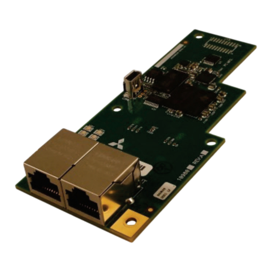
- Page 23 Unpacking and Product Confirmation 1.3.1 Shipment Confirmation Check the enclosed items. Confirm that the correct quantity of each item was received, and that no damage occurred during shipment. Plug-in option: qty. 1 Communication option LED display cover: qty. 1 5.5mm Spacer: qty. 3 M3 x 8mm Mounting screws: qty.
- Page 24 1.3.2 Component Overview Spacer mounting hole USB port Screw mounting hole LEDs (Refer to section 1.4) Spacer mounting hole Spacer mounting hole Inverter connector Ethernet Port 1 (on bottom side) Ethernet Port 2 Screw mounting hole PRE-OPERATION INSTRUCTIONS █...
- Page 25 LED Indicators The option board contains several bi-color LEDs (visible through the LED display cover after mounting) that provide a visual indication of the unit’s overall status. Network Status / LED4 Ethernet Port 1 Ethernet Port 2 Module Status / LED3 1.4.1 Port Status LED Description Ethernet Port 1 (P1 LNK/ACT) and Ethernet Port 2 (P2 LNK/ACT) LED Activity...
- Page 26 1.4.2 Standard LED Description Module Status (MS) LED Activity Status Note Device Off The inverter power is off Green Blink, Startup Startup blink sequence Red Blink Green On Device On Normal status Discovery Green Blink PROFINET discovery and identification (DCP) Identification Red Blink Error Code...
- Page 27 1.4.3 EtherCAT LED Description Run (LED3) LED Activity Slave State Note Device Off or The inverter power is off or the device is in state INIT INITIALISATION Green Blink, Startup blink sequence; the device is booting and has not yet entered Red Blink or INITIALISATION the INIT state...
- Page 28 INSTALLATION Pre-Installation Instructions Check that the inverter’s input power and the control circuit power are both OFF. Caution To prevent explosions or similar damage, do not install or remove the plug-in option with input power ON. • To prevent damage from electrostatic discharge, always touch a grounded piece of metal prior to touching any •...
- Page 29 Installation Procedure Installing the communication option LED display cover Remove the inverter’s front cover (refer to chapter 2 of the inverter’s Instruction Manual (Detailed) for information on how to remove the front cover.) Cut off the tabs on the back side of the inverter’s front cover with a nipper, etc.
- Page 30 Installing the option Insert spacers from the back side of the option card into the 3 mounting holes as indicated. Securely attach the option card to the inverter’s option Connector 1 (refer to Figure 1 on page 30 for the location of Connector 1 on the inverter’s control board).
- Page 31 Figure 1: Installation Positions of Screws and Spacers █ INSTALLATION...
- Page 32 • To minimize the possibility of damage, hold only the sides of the circuit board when installing or uninstalling the plug-in option. Stress applied to circuit board components by directly pressing/pulling on them may cause component damage and subsequent failure. Use caution to avoid dropping mounting screws into the inverter enclosure when installing or uninstalling the plug-in •...
- Page 33 INVERTER SETTINGS The inverter parameters listed in Table 12 are critical for overall operation of the end-to-end communication system. Some of these parameters must be set to specific values, and some may have multiple allowable settings depending on the desired operation of the overall application. Although there may be many other inverter parameters that will require configuration for your specific application, it is important to understand the manner in which the following parameters will impact successful communications with, and control of the inverter.
- Page 34 Network Setting The network settings can optionally be set using the inverter parameters described in this section. However, to avoid invalid configuration, it is recommended to use the Configuration Studio to modify the network settings whenever possible. Please consult with your network administrator for the proper settings of these fields. 3.1.1 IP Address (Pr.
- Page 35 Operation Mode Setting Three operation modes are available when a communication option card is installed into an inverter. 1. PU operation [PU] ...... The inverter is controlled by the operating panel (FR-DU08). 2. External operation [EXT] .... The inverter is controlled by the ON/OFF switching of external signals connected to the control circuit terminals (factory default.) 3.
- Page 36 3.2.2 Operation Mode Switching & Comm. Startup Mode (Pr. 79, Pr. 340) Operation mode switching conditions Prior to switching the operation mode, confirm that: • The inverter is stopped Both the STF and STR signals are off • • The Pr.
- Page 37 Pr. 340 Pr. 79 Operation Mode at Power-On or Power Operation Mode Switchover Setting Setting Recovery Switching among external, PU, and NET External operation mode (default) operation modes is enabled PU operation mode PU operation mode fixed Switching between external and NET External operation mode operation modes is enabled, switching to PU operation mode is disallowed...
- Page 38 The operation mode cannot be directly changed between PU mode and NET mode. Pr. 340 settings "2” and “12" are mainly used for communication operation using the inverter’s RS-485 port. When a value other than "9999" (automatic restart after momentary power failure) is set in Pr. 57 Restart coasting time, the inverter will resume the same operation state which it was in prior to a momentary power failure if such a failure occurs.
- Page 39 2 is invalid.) Communication option card control is valid (A8NETH- 2P control is valid.) Control via the inverter’s RS-485 port (A8NETH-2P NET mode operation control is invalid.) command source 9999 Communication option automatic recognition.
- Page 40 Communication EEPROM Write Selection (Pr. 342) When parameters are written via communications, by default both volatile RAM and nonvolatile EEPROM contents are modified. Due to the limited write cycle lifetime of EEPROM memory, however, it may be desirable to modify only the contents of RAM when frequent parameter writes via communications are necessary.
- Page 41 REGISTER NUMBERING AND BEHAVIOR Register Numbers All accessible inverter parameters are referenced by their register number as defined in Table 13 and can be conveniently referenced in the Configuration Studio (section 5.6) and the embedded web server (section 6.2.3). Note that the register list is not exhaustive, the registers may not exist for all inverters, and the register data contents may vary depending on the inverter.
- Page 42 Table 13: Register Parameter List Register Description Command register (refer to section 4.3) Inverter reset (refer to section 4.4) Alarm history clear (refer to section 4.5) All parameter clear (refer to section 4.6) Inverter state (refer to section 4.7) Output frequency Output current Output voltage Frequency setting value...
- Page 43 Register Description Cumulative power Position command (lower 16 bits) Position command (upper 16 bits) Current position (lower 16 bits) Current position (upper 16 bits) Drop pulse (lower 16 bits) Drop pulse (upper 16 bits) Torque order Torque current order Motor output Feedback pulse Trace status PLC function user monitor 1...
- Page 44 Register Description Cumulative regenerative power PID measured value 2 Second PID set point Second PID measured value Second PID deviation Cumulative pulse Cumulative pulse carrying-over times Cumulative pulse (control terminal option) Cumulative pulse carrying-over times (control terminal option) Integrated power on time Running time Saving energy monitor Fault code 1 –...
- Page 45 Register Description 1226 DriveControl 1227 DriveStatus (lower 16 bits) (refer to section 4.8) 1228 DriveStatus (upper 16 bits) 1229 SetpointSpeed (refer to section 4.9) 1230 CommandSpeed 1231 ActualSpeed (refer to section 4.10) 1232 SpeedScaleNumerator (lower 16 bits) 1233 SpeedScaleNumerator (upper 16 bits) 1234 SpeedScaleDenominator (lower 16 bits) 1235...
- Page 46 Register Description 1254 QuickDecelerationDeltaSpeed (upper 16 bits) 1255 QuickDecelerationDeltaTime (lower 16 bits) 1256 QuickDecelerationDeltaTime (upper 16 bits) 1257 MaxSpeed (lower 16 bits) 1258 MaxSpeed (upper 16 bits) 1259 MinSpeed (lower 16 bits) 1260 MinSpeed (upper 16 bits) 1261 TargetTorque 1262 ActualTorque 1263 TorqueSlope (lower 16 bits)
- Page 47 Scanned Registers All registers are constantly being “scanned” by the interface card, which is to say that they are constantly being read and/or written (as applicable), and their current values are therefore mirrored in the interface card’s internal memory. The principle disadvantage of scanned registers is that write data checking is not available. This means that when the value of a scanned register is modified via a network protocol or via the web browser’s monitor tab, the interface card itself is not able to determine if the new value will be accepted by the inverter (the value may be out-of-range, or the inverter may be in a state in which it will not accept new values being written via communications, etc.) For example, if a write is performed to...
- Page 48 Inverter Command Register The command word is register 1 and the bit-mapping is described in Table 14. These bits are mapped to DriveControl (register 1226). Table 14: Inverter Command Register Mapping Significance Value Description Reserved Not used Enable operation EnableOp Disable operation Enable reverse operation EnableRevOp...
- Page 49 Inverter Reset Register The inverter reset register is register 5. A value of 0x9696 or 0x9966 will reset the inverter. Alarm History Clear Register The alarm history clear is register 6. A value of 0x9696 will clear the alarm history. All Parameter Clear Register The all parameter clear is register 7.
- Page 50 Inverter State Register The inverter state is register 102 and the states are listed in Table 16. Table 16: Inverter State Value Description NOT_READY_TO_SWITCH_ON SWITCH_ON_DISABLED READY_TO_SWITCH_ON SWITCHED_ON OPERATION_ENABLED DISABLE SHUTDOWN QUICK_STOP FAULT_REACTION_ACTIVE FAULTED REGISTER NUMBERING AND BEHAVIOR █...
- Page 51 DriveStatus Register The DriveStatus is register 1227 and the bit-mapping is described in Table 17. Table 17: DriveStatus Register Mapping Significance Value Description Power supply is switched on, electronics initialized, main contact, if available, has dropped out, pulses are inhibited ReadyToSwitchOn Voltage at the power converter, i.e.
- Page 52 Significance Value Description Internal (manufacturer specific) limitation is active (e.g. current, power or speed limit) LimitActive 12 - 13 Reserved Not used Drive function enabled in reverse mode RevOpEnabled Drive is stopping Stopping SetpointSpeed Register The SetpointSpeed is register 1229 and specifies the target speed in RPM. A positive value indicates forward motion, while a negative value indicates reverse motion.
- Page 53 MITSUBISHI CONFIGURATION STUDIO Overview Figure 2: Mitsubishi Configuration Studio The card is discovered, configured and updated by the Mitsubishi Configuration Studio PC application. The studio must be installed prior to connecting a card to ensure that the appropriate USB drivers are installed. The studio will typically require a █...
- Page 54 USB connection for reading/writing a configuration and updating the firmware. Depending on the currently-active drivers, remote discovery, network setting, and firmware updates are also possible via Ethernet. The latest release of the Configuration Studio can be downloaded from the product web page.
- Page 55 When the studio goes online with a device, its configuration is automatically read. While the studio is online with a device, it will appear in green text in the Discovered Devices panel. The studio may be online with multiple devices simultaneously. Uploading a Device’s Configuration into a Project The current configuration of an online device can be uploaded into the Project panel by selecting a device under the Online Devices list heading and then:...
- Page 56 Hit the <DELETE> key on the keyboard when the device is selected in the Project panel. • • Right-click on the device in the Project panel and choose Go Offline from the context-sensitive menu. Select Go Offline with Device from the Edit menu when the device is selected. •...
- Page 57 General Object Editing Activities The following editing activities apply for all types of configuration objects and project elements. Adding an Object To add an object, click on an item (protocol driver or Node, for example) in the Project panel. Any available objects for that item will be listed in the Available Objects panel (the panel title depends on the currently-selected item).
- Page 58 Hitting the <DELETE> key on the keyboard when the object is selected in the Project panel. • • Right-clicking on the object in the Project panel and choosing Remove from the context-sensitive menu. Selecting Remove Selected Item from the Edit menu when the object is selected. •...
- Page 59 Note that the studio allows you to copy and paste items between different locations, including different devices. This is useful for copying partial configurations from one device to another. Reordering Objects Objects can be reordered in the Project panel by dragging the item to the desired location. If the item is dragged outside of the items in the project tree, it will be moved to the end.
- Page 60 Internal Logic Settings 5.4.1 Fail-safe Values 5.4.1.1 Overview The card can be configured to perform a specific set of actions when network communications are lost (timeout event). This allows each inverter parameter to have its own unique “fail-safe” condition in the event of network interruption. Support for this feature varies depending on the protocol: refer to the protocol-specific section of this manual for further information.
- Page 61 Description This field is strictly for user reference: it is not used at any time by the device. Register Enter the register number (refer to section 4) corresponding to the inverter parameter. Data Type This is the size of valid values and is fixed to “16-Bit Unsigned” allows for a range of timeout values between 0 and 65535. Value Enter the “fail-safe”...
- Page 62 Discovery over Ethernet Depending on the currently-enabled driver, the Configuration Studio will automatically discover the device on the current Ethernet network, regardless of whether or not the card’s network settings are compatible with the subnet upon which they reside. All connected devices are automatically added to the Discovered Devices panel.
- Page 63 Manage Device Parameters The accessibility and scan priority of the inverter parameters can be adjusted (refer to Figure 5). This is an advanced feature and must only be used after consulting technical support to determine the appropriate settings for the target application.
- Page 64 Backup and Restore Parameters The parameter values can be backed up from the inverter and restored to the inverter (refer to Figure 6 and Figure 7). This allows for easy inverter cloning. The backup parameter values are stored as a CSV file. A parameter value can be excluded by disabling the corresponding checkbox.
- Page 65 Figure 7: Restore Parameters █ MITSUBISHI CONFIGURATION STUDIO...
- Page 66 Restore Factory Settings The interface card (connected via USB) can be restored to the factory settings. Note that the filesystem will be reformatted, which will destroy all custom modifications and configurations. Please backup the configuration before executing this feature. The factory settings can be restored by: Right-clicking on the device in the Project panel and choosing Restore Factory Settings.
- Page 67 EMBEDDED WEB SERVER Overview The interface contains an embedded (HTTP) web server, which allows users to access the inverter’s internal data in a graphical manner with web browsers such as Microsoft Internet Explorer or Mozilla Firefox. In this way, the inverter can be monitored and controlled from across the room or from across the globe.
- Page 68 Figure 8: Embedded Web Server EMBEDDED WEB SERVER █...
- Page 69 Monitor Tab 6.2.1 Information Window Figure 9: Monitor Tab Information Window Figure 9 shows the Information Window, which displays messages regarding the status of the interface card or web browser session. There is also an “ACTIVITY” indicator which blinks periodically to show the status of data communication between the web browser and the interface card.
- Page 70 parameter (Pr. XXX) number that is normally used when accessing a given register via the inverter’s keypad. Note that not all registers will have parameter number entries: command and monitor registers, for example, are not accessed via the inverter’s keypad by entering a “Pr. XXX” number, and their associated parameter column fields on the Monitor tab are therefore empty.
- Page 71 Some items to keep in mind when interacting with the Parameter List are: • When entering new parameter values, be sure that the number being entered is appropriate for the currently-selected radix (refer to section 6.2.5). The column widths can be changed by dragging the vertical bars that separate the header row’s cells. •...
- Page 72 Dashboard Tab Figure 14: Dashboard Tab The Dashboard Tab provides access to a variety of gauges, meters and graphs that can be configured to provide an at-a- glance graphical overview of application variables in real-time. A total of 10 gauge windows are available (four at a time), EMBEDDED WEB SERVER █...
- Page 73 and each gauge window can be configured to display any register’s value via one of six different gauge types. User-defined engineering units, scaling and range limits are also configurable. Refer to Figure 14. 6.3.1 Information Window Figure 15 shows the Information Window, which displays messages regarding the status of the Dashboard configuration parameters (loading or submitting).
- Page 74 be reflected on the gauge. Multiplier: The multiplier value is a floating-point number that is used to scale the raw value of a register. As its name suggests, the multiplier value is multiplied by the designated register’s current raw value in order to calculate the gauge’s indicated value.
- Page 75 BarGraph: Refer to Figure 18. This type of meter implements a linear bar graph display format. Hovering the mouse pointer over the red portion of the graph pops up a tooltip which displays the current indicated value and units. Figure 18: BarGraph Meter: Refer to Figure 19.
- Page 76 Pos/Neg Meter: Refer to Figure 20. Similar to the “meter” gauge, this type of meter also implements a common panel meter-type display format, but in this instance the indicated value can be positive or negative (two’s complement interpretation). In other words, raw register values of 0…0x7FFF equate to 0...32767 , and values of 0x8000...0xFFFF equate to -32768...-1.
- Page 77 Line Graph: Refer to Figure 22. This type of graph implements a continuously-scrolling historical data logging line graph. Up to 80 seconds worth of historical data is available. Hovering the mouse pointer anywhere on the graph displays a vertical reference line at the corresponding time, and pops up a tooltip which displays the current indicated value at that time.
- Page 78 6.3.4 Submitting Changes Whenever any of the gauge window configuration items in the Dashboard Tab have been changed, the “submit” button located on the right-hand portion of the web page must be selected in order to write these settings to the interface card’s filesystem. Refer to Figure 24.
- Page 79 Customizing the Embedded Web Server 6.4.1 Customization Overview It is possible for end-users to customize the embedded web server in order to create their own application-specific or corporate “look and feel”. Knowledge of authoring dynamic web content is required. Using windows explorer, it is possible to load customized web server content into the “WEB”...
- Page 80 XTPro is a request/response protocol that provides services specified by commands. For more information on XTPro, refer to the separate XTPro Specification. This section will cover the device-specific implementation of the XTPro protocol. 6.4.3 XTPro Web Browser-Based Implementation A representative implementation based upon using a web browser as the client is detailed in Figure 25. In this scenario, the client application is developed by using an active web server authoring tool (such as Adobe Flash®).
- Page 81 trogrammer authors active web page content (via Adobe Content is loaded onto Flash, etc.) server device’s file system for web server Active web content http://192.168.16.111 is delivered to client Network or User accesses HTTt (port 80) Internet server’s web page via web Server browser (client) Device...
- Page 82 6.4.4 XTPro HMI-Based Implementation A representative implementation based upon a stand-alone HMI client is detailed in Figure 26. In this scenario, the client application is developed by using tools provided by the HMI manufacturer, and is hosted independently of the actual server device.
- Page 83 6.4.5 XTPro Supported Commands For a summary of the supported XTPro commands, refer to Table 18. Note that two simultaneous XTPro connections are available. Table 18: Supported XTPro Commands Command Supported Notes noop Supports XTPro specification version 1 read_data “reference” is the inverter’s register (e.g. “1227” for SetpointSpeed command), while “data_value”...
- Page 84 FILESYSTEM Overview The interface card’s on-board filesystem is used by the application firmware. Currently, the application firmware’s main use of the filesystem is to store XML-encoded configuration files and the embedded web server. The studio must be used to manage the configuration via USB or FTP. Do not manually access the configuration files unless instructed by technical support.
- Page 85 USB with Windows Explorer To use Microsoft Windows Explorer, first open either “Windows Explorer” or “My Computer”. Refer to Figure 27. Note that the indicated procedure, prompts and capabilities outlined here can vary depending on such factors as the installed operating system and service packs.
- Page 86 Figure 29: USB File Access via Windows Explorer FILESYSTEM █...
- Page 87 FTP With Windows Explorer To use FTP with Microsoft Windows Explorer, first open either “Windows Explorer” or “My Computer”. Please note that the indicated procedure, prompts and capabilities outlined here can vary depending on such factors as the installed operating system, firewalls and service packs.
- Page 88 Loading New Web Server Content The interface card’s web server resides in the file system and can be updated in the field (refer to section 6.4). This section will discuss how to update the default web server. The update procedure similarly applies to a custom web server. Web server updates may be released for a variety of reasons, such as improvements and added functionality.
- Page 89 FIRMWARE Overview The interface card’s embedded firmware can be updated in the field. Firmware updates may be released for a variety of reasons, such as custom firmware implementations, firmware improvements and added functionality as a result of user requests. Additionally, it may be necessary to load different firmware onto the unit in order to support various protocols. In order to ensure that the firmware update is successful, and in the interest of equipment and personnel safety, it is strongly recommended to stop all of the card’s production activities prior to initiating the firmware update procedure.
- Page 90 After the firmware update has been completed, the card will reset automatically. When the card boots up again, it will be running the new application firmware, which can be confirmed by observing the version displayed in the Device…Device Info or the web server’s information window (refer to section 6.2.1). If new default web server content is available, load the new web server (refer to section 7.4).
- Page 91 PROTOCOL-SPECIFIC INFORMATION This section will discuss topics that are specific to each of the supported protocols. Modbus/TCP 9.1.1 Overview Table 19: Supported Modbus/TCP Functions The interface card supports Schneider Electric’s Modbus/TCP protocol, release Function Modbus/TCP 1.0. The interface is conformance class 0 Function Code Class...
- Page 92 The driver can be configured to detect a timeout (communication loss) and perform a timeout action. • 9.1.2 Holding & Input Registers The inverter registers by default are mapped as both holding registers (4X) and input registers (3X), and are accessed by using the inverter register numbers described in section 4.1.
- Page 93 Therefore, reading coil #34 will return the value of register #3, bit #1. 9.1.4 Connection Timeout Options In the studio’s Project panel, navigate to A8NETH-2P…Ethernet…Modbus/TCP Server. The following configuration options will determine the actions to be taken if the connection is abnormally terminated or lost. While this feature provides an additional level of fail-safe functionality for those applications that require it, there are several ramifications that must be understood prior to enabling this capability.
- Page 94 There are no node settings. A node is simply a container for objects. 9.1.6 Holding/Input Register Remap Settings In the studio’s Project panel, add A8NETH-2P…Ethernet…Modbus/TCP Server…Holding/Input Register Remap. Holding/input register remap objects are OPTIONAL. By default, all inverter registers are already mapping as both holding (4X) and input (3X) registers (refer to section 9.1.2).
- Page 95 inverter’s output frequency (register 201), converter output voltage (register 208), and PID deviation value (register 254), this could be accomplished in two different ways: Implement three separate Modbus read transactions, each one reading one register only, or Implement one single Modbus read transaction, starting at register 201 for a quantity of 54 registers. Then, pick out the registers of interest and ignore the rest of the response data.
- Page 96 EtherNet/IP 9.2.1 Overview EtherNet/IP is a network adaptation of ODVA’s Common Industrial Protocol (CIP). The card supports the EtherNet/IP server protocol, including the CSP server variant. The interface card supports both implicit (class 1 I/O) and explicit (UCMM and class 3) messaging. Class 1 connections support two different types of I/O messaging.
- Page 97 1 connections. 9.2.2 Server Settings In the studio, navigate to A8NETH-2P…Ethernet…EtherNet/IP Server. Device Name The device name is used for identification of a device on the EtherNet/IP network. This string is accessible as the “product name”...
- Page 98 9.2.3 Connection Timeout Options In the studio’s Project panel, navigate to A8NETH-2P…Ethernet…EtherNet/IP Server. The following configuration options will determine the actions to be taken if the connection is abnormally terminated or lost. While this feature provides an additional level of fail-safe functionality for those applications that require it, there are several ramifications that must be understood prior to enabling this capability.
- Page 99 9.2.4 Generic Class 1 I/O Produced and Consumed Data Settings In the studio’s Project panel, add A8NETH-2P…Ethernet…EtherNet/IP Server…Produced I/O Data…Produced Data Word and/or Consumed I/O Data…Consumed Data Word. The Produced Data Word and Consumed Data Word objects are only applicable when connecting to assembly instances 100 and 150 (generic I/O), which is typically the case.
- Page 100 Data Type Each data word is fixed to 16-Bit Unsigned. This is equivalent to two bytes. Table 20: EtherNet/IP User-Configurable I/O Data Format Consumed Data Produced Data (PLC to Inverter) (Inverter to PLC) Word Offset Register Word Offset Register The default I/O configuration is described in Table 21. Always use the studio to confirm the configuration before commissioning the device.
- Page 101 9.2.6 AC/DC Drive Profile Class 1 (I/O) Connection Access The interface card supports the ODVA AC/DC drive profile. No special EtherNet/IP configuration of the interface card is required when using the AC/DC drive profile: all that is needed is that the controller must target either assembly instances 20 &...
- Page 102 Table 23: Output Instances 20 and 21 Detail Instance Byte Bit 7 Bit 6 Bit 5 Bit 4 Bit 3 Bit 2 Bit 1 Bit 0 Fault Run Fwd Reset Speed Reference (Low Byte) Speed Reference (High Byte) Fault NetRef NetCtrl Run Rev Run Fwd...
- Page 103 Table 24: Input Instances 70 and 71 Detail Instance Byte Bit 7 Bit 6 Bit 5 Bit 4 Bit 3 Bit 2 Bit 1 Bit 0 Running1 Faulted Speed Actual (Low Byte) Speed Actual (High Byte) Ctrl Running2 Running1 From From Ready Warning...
- Page 104 AtReference: Up-to-speed signal (0=not up-to-speed, 1=up-to-speed). Maps to inverter register 1227 (DriveStatus) bit 10 (SetpointReached). Drive State: Indicates the current state of the Control Supervisor Object state machine. Refer to the ODVA EtherNet/IP specification (object library) for detailed information on the Control Supervisor Object state machine. Speed Actual: Inverter operating speed in RPM.
- Page 105 9.2.9 Inverter Register Access Tag Format Any inverter register (refer to section 4) can be accessed with its own unique tag name, or an array tag can be used to access a group of registers with one PLC instruction. Tag names are generated according to the following structure: [reg]_[register number] Where [reg] is just the 3-character sequence “reg”.
- Page 106 9.2.10 ControlLogix Examples: Setup This section will demonstrate how to initially setup a ControlLogix PLC (such as a 1756-L61) coupled with a 1756-ENBT communication interface (adjust this procedure according to your specific equipment). Later sections will provide specific read/write examples using this configuration with I/O or explicit messaging. Run RSLogix 5000, and create a new configuration.
- Page 107 The “New Module” window will open. Refer to Figure 32. Figure 32: Identifying the New Module Assign the Ethernet module a name (we will use “EIP”) and an IP address, deselect “Open Module Properties”, and click OK. Download the configuration. Switch to online mode.
- Page 108 9.2.11 ControlLogix Example: EDS Add-On Profile (AOP) This section will demonstrate how to setup and use an EtherNet/IP I/O connection via EDS Add-On Profile. This example only applies to RSLogix5000 V20 (and later) that support EDS Add-On Profile. Otherwise, refer to the I/O examples in section 9.2.12.
- Page 109 Figure 34: EDS Registration Ensure that there are no errors in the test results. Click “Next”. A graphic image of the interface card is displayed. Click “Next”. The task summary will list the interface card as the device to register. Click “Next”. “You have successfully completed the EDS Wizard”.
- Page 110 11) Find the interface card in the “Select Module” dialog box as shown in Figure 35. Figure 35: Adding a New Interface Card Module PROTOCOL-SPECIFIC INFORMATION █...
- Page 111 12) The “New Module” properties dialog box will open as shown in Figure 36. Figure 36: AOP Interface Card Module Properties █ PROTOCOL-SPECIFIC INFORMATION...
- Page 112 13) Click on the “Connection” tab. Refer to Figure 37. Figure 37: AOP New Module Properties Connection Tab Confirm the setting of the “Requested Packet Interval (RPI)”. The RPI defines the amount of time (in milliseconds) between data exchanges across an I/O connection. The smallest RPI supported by the interface card is 1ms. Click “OK” when done. PROTOCOL-SPECIFIC INFORMATION █...
- Page 113 14) You should now see the interface card in the 1756-ENBT/A branch under the I/O Configuration in the controller organizer view. The full I/O Configuration tree should appear similar to Figure 38. Figure 38: AOP Interface Card I/O Configuration 15) Continue with the AOP Generic I/O Messaging example in section 9.2.11.1 or AOP AC/DC Drive Profile example in section 9.2.11.2.
- Page 114 Figure 39: AOP Generic I/O Module Definition In the “Connection” portion of the dialog box, enter the following information: Name: In this example, select Generic I/O. Size: Because all inverter data is stored as 16-bit function codes, change the data type to “INT array”. Input: The Input is the collection of monitor data that is produced by the interface card and is received as an input to the PLC.
- Page 115 For the purposes of this example, we are assuming that the default consumed data word configuration, with 2 relevant registers (1227 and 1231). We therefore set the Output Size to 2 Words. When done, click “OK”. Switch to online mode and download the project to the PLC. Verify that the newly-added inverter is available and operating correctly by observing any indications shown on the inverter’s icon.
- Page 116 Figure 40: AOP AC/DC Drive Profile Module Definition In the “Connection” portion of the dialog box, enter the following information: Name: In this example, select AC/DC Drive Profile 21 71. Size: Because all inverter data is stored as 16-bit function codes, change the data type to “INT array”. When done, click “OK”.
- Page 117 status and any available error messages will be displayed in the area below the project tree. Also confirm that the interface card’s “Network Status” LED should be solid green, indicating an “online/connected” state. By double-clicking “Controller Tags” in the project tree, it is possible to view the newly-added tags. The Interface_Card:I tag allows viewing of the input data, and the Interface_Card:O tag allows modification of the output data.
- Page 118 9.2.12 ControlLogix Example: I/O Messaging This section will demonstrate how to setup and use an EtherNet/IP I/O connection via vendor-specific assembly instances 100 & 150 or 20 & 70 or 20 & 71. Do not complete this example if you are using EDS AOP, in which case, please refer to the AOP examples.
- Page 119 the Produced Register Configuration as described in section 9.2.4. The Input Assembly Instance must be set to 150 when connecting to the generic I/O assembly instances (or 70/71 when using the ODVA AC/DC drive profile), and the size must be set to the number of 16-bit registers that we wish to receive from the interface card. For the purposes of this example, we are assuming that the default produced data word configuration, with two relevant registers (1227 and 1231).
- Page 120 You should now see the new module (named “ETHERNET-MODULE Interface_Card”) in the 1756-ENBT branch under the I/O Configuration in the controller organizer view. Right click on this new module, choose “Properties”, and select the Connection tab. Refer to Figure 43. Confirm the setting of the Requested Packet Interval (RPI).
- Page 121 output data (Interface_Card:O.Data[0]) has been set to a hexadecimal value of 0xC002. The default consumed data word configuration word offset 0 references register 1, which is the inverter’s command register. A value of 0xC002, therefore, means that the NetCtrl, NetRef, and EnableOp bits have been turned ON. Figure 45: Online Module Status Figure 46: Controller Tags for I/O Access Similarly, we can see that the second 16-bit word of output data (Interface_Card:O.Data[1]) has been set to a decimal...
- Page 122 Complete all the steps in section 9.2.12. Right click on “Add-On Instructions” in the controller organizer view and select “Import Add-On Instruction”. Browse and import the generic default I/O add-on instruction. Refer to Figure 47. Double click “Controller Tags” in the controller organizer view and select the “Edit Tags” tab at the bottom. Create the tags shown in Figure 48.
- Page 123 11) The program is now complete. 12) Save, download and run the program. Figure 49: Add Generic Default Add-On Instruction Figure 50: Configure Generic Default AOI █ PROTOCOL-SPECIFIC INFORMATION...
- Page 124 9.2.12.2 ControlLogix Example: AC/DC Drive Profile Add-On Instruction The AC/DC drive profile add-on instruction is a simple interface to command and monitor the inverter. It is based on the assembly instances 21 & 71. The add-on instruction is optional and provided for user convenience. Complete all the steps in section 9.2.12.
- Page 125 Create the tags shown in Figure 53. Double click “MainRoutine” under Tasks …MainTask …MainProgram in the controller organizer view. Right click on the first ladder logic rung in the MainRoutine window and select “Add Ladder Element...” The “Add Ladder Element” window appears. Select the AC/DC drive profile add-on instruction in the Add-On folder.
- Page 126 Figure 54: Add AC/DC Drive Profile Add-On Instruction Figure 55: Configure AC/DC Drive Profile AOI 12) Save, download and run the program. PROTOCOL-SPECIFIC INFORMATION █...
- Page 127 9.2.13 ControlLogix Example: Read Registers This example program will show how to continuously read a block of registers from the inverter with a single MSG instruction. Only one read request is outstanding at any given time. Create new Tags. Double click “Controller Tags” in the controller organizer view. The “Controller Tags”...
- Page 128 Add a MSG instruction to the main program. Double click “MainRoutine” under Tasks …MainTask …MainProgram in the controller organizer view. Right click on the first ladder logic rung in the MainRoutine window and select “Add Ladder Element...” The “Add Ladder Element” window appears. Select the “MSG”...
- Page 129 Configure the MSG instruction. Edit the “Message Control” field on the MSG instruction to use the previously-created “connection” tag. Refer to Figure 59. Click the message configuration button (“…”) in the MSG instruction. The “Message Configuration” window will open. Refer to Figure 60. Figure 59: MSG Instruction Tag Assignment “Configuration”...
- Page 130 In our example, this path would be entered as “EIP,2,192.168.16.163”. If “Cache Connections” is enabled (checked), the connection remains open after transmission. If disabled (unchecked), the connection is opened before and closed after every transmission. For efficiency, it is recommended to enable “Cache Connections”.
- Page 131 Figure 64: Complete Program Figure 63: Configure XIO Element Save, download and run the program. To view the values of the registers being read from the interface card, double-click “Controller Tags” in the controller organizer view. Select the “Monitor Tags” tab and expand the data_array tag. 25 register values starting at register #201 are being continuously read from the interface card and placed in the 25 sequential offsets of data_array starting at the 0 offset.
- Page 132 9.2.14 ControlLogix Example: Reading and Writing Multiple MSG Instructions Often times, applications may need to both read data from and write data to the inverter. To accomplish this task, multiple MSG instructions will need to be implemented in the PLC program. The configuration and execution for implementing multiple MSG instructions is in general identical to that required for implementing just one MSG instruction.
- Page 133 Figure 66: MSG Configuration for Writing Note that when writing data via explicit messaging, use caution to ensure that the commanded function codes are not also simultaneously being commanded in the background via I/O messaging. Indeterminate behavior can occur if MSG instructions and background I/O data transfers are both writing to the same function codes.
- Page 134 Allen Bradley CSP (PCCC) 9.3.1 Overview Ethernet-enabled Allen-Bradley legacy PLCs (such as the PLC5E, SLC-5/05, and MicroLogix series) use a protocol called CSP (Client Server Protocol) to communicate over the Ethernet network. The flavor of CSP used by these PLCs is also known as “PCCC”...
- Page 135 9.3.3 Inverter Register File Number Offset Format The formula to calculate which register is targeted in the interface card is provided in Equation 3. target register file number offset × Equation 3 In Equation 3, “target register” ∈[1…3299], “file number” ∈[10…42] (which means N10…N42), and “offset” is restricted only by the limitations of the programming software (but is a value of 3299 max).
- Page 136 Because both the EtherNet/IP consumed and produced data word configurations are comprised of 32 register definitions, the targeted “offset/element” must be within the range of 0 to 31 inclusive. Refer to Table 26 for some examples of N50 accesses. Table 26: Examples of EtherNet/IP-Style Bulk Access via File N50 File/Section Address Start Target Register of...
- Page 137 9.3.4 SLC-5/05 Example: Read Registers This example program will show how to continuously read a block of registers from the inverter with a single MSG instruction. This action is performed via the Typed Read (a.k.a. “PLC5 Read”) message type. Only one read request is outstanding at any given time.
- Page 138 Figure 69: MSG Instruction Selection Figure 68: Creating a Data File Right click on the default rung number on the left-hand side of the LAD2 window and select “Insert Rung”. Right click on the rung number of the new editable rung and select “Append Instruction”. Select the “MSG”...
- Page 139 Select the “XIO” instruction from the “Bit” classification, then click OK. Refer to Figure 70. Configure the MSG instruction. Set the “Read/Write” field to “Read”, “Target Device” field to “PLC5”, “Local/Remote” field to “Local”, and “Control Block” to “N20:0”. Upon hitting the <ENTER> key while in the “Control Block”...
- Page 140 Figure 72: MSG Configuration, "MultiHop" Tab Figure 71: MSG Configuration, "General" Tab Assign a tag to the XIO element. Double-click on the XIO element located to the left of the MSG block. Type in N20:0/15 (MSG instruction’s enable bit). This configuration causes the MSG instruction to automatically retrigger itself when it completes.
- Page 141 The program is now complete. Refer to Figure 74. Save, download, and run the program. To view the registers being read from the interface card, double-click the data file N18 under “Data Files” in the controller organizer view. 25 register values starting at register #201 are being continuously read from the interface card and placed in the 25...
- Page 142 9.3.5 SLC-5/05 Example: Reading and Writing Multiple MSG Instructions Often times, applications may need to both read data from and write data to the inverter. To accomplish this task, multiple MSG instructions will need to be implemented in the PLC program. The configuration and execution for implementing multiple MSG instructions is in general identical to that required for implementing just one MSG instruction.
- Page 143 Figure 77 shows the configuration details of the “write” MSG instruction. Note that this instruction will only be writing to one inverter register: namely, the command word (Target Data Table Address is N10:1, which equates to inverter register 1). The source Data Table Address in this case is N18:30. Figure 77: MSG Configuration for Writing █...
- Page 144 Date: May 26, 2016 Vendor Name: ICC, Inc. Product Name: Mitsubishi Inverter FR-800 Product Model Number: A8NETH-2P Applications Software Version: V1.1.1 Firmware Revision: V1.1.1 BACnet Protocol Revision: Product Description: The Mitsubishi 800-series inverter family delivers multi-use performance, accuracy and system flexibility in an ultra-reliable hardware package.
- Page 145 Data Sharing – WriteProperty-B (DS-WP-B) Device Management – Dynamic Device Binding-B (DM-DDB-B) Device Management – Dynamic Object Binding-B (DM-DOB-B) Segmentation Capability: None Able to transmit segmented message Window Size ________ Able to receive segmented message Window Size ________ Standard Object Types Supported: See “Object Types/Property Support Table”.
- Page 146 Networking Options: Router, Clause 6 - List all routing configurations Annex H, BACnet Tunneling Router over IP BACnet/IP Broadcast Management Device (BBMD) Does the BBMD support registrations by Foreign Devices? Networking Security Options: Non-secure Device – is capable of operating without BACnet Network Security Secure Device –...
- Page 147 Datatypes Supported: The following table summarizes the datatypes that are accepted (in the case of a write property service) and returned (in the case of a read property service) when targeting the present value property of each supported object type. Service Object Type Read Property...
- Page 148 Object Types/Property Support Tables: Table 27: BACnet Device Object Types /Properties Supported Object Type Property Device Object Identifier Object Name Object Type System Status Vendor Name Vendor Identifier Model Name Firmware Revision Appl Software Revision Protocol Version Protocol Revision Services Supported Object Types Supported Object List Max APDU Length...
- Page 149 Table 28: BACnet Binary Object Types /Properties Supported Object Type Property Binary Binary Binary Input Output Value Object Identifier Object Name Object Type Present Value Status Flags Event State Out-of-Service Priority Array Relinquish Default Polarity Active Text Inactive Text R – readable using BACnet services W –...
- Page 150 Table 29: BACnet Analog Object Types /Properties Supported Object Type Property Analog Analog Analog Input Output Value Object Identifier Object Name Object Type Present Value Status Flags Event State Out-of-Service Units Priority Array Relinquish Default R – readable using BACnet services W –...
- Page 151 Table 30: BACnet Multi-state Object Types /Properties Supported Object Type Property Multi-state Multi-state Multi-state Input Output Value Object Identifier Object Name Object Type Present Value Status Flags Event State Out-of-Service Number of States Priority Array Relinquish Default R – readable using BACnet services W –...
- Page 152 9.4.2 Default Supported Objects This section will describe the default objects. Since the objects are configurable, the system integrator is responsible for managing, maintaining, and documenting the actual configuration. Always use the studio to confirm the configuration before commissioning the device. Table 31: Binary Input Object Instance Summary Active Text Instance ID...
- Page 153 Table 32: Binary Output Object Instance Summary Active Text Instance ID Object Name Description Register Bit (Mask) Inactive Text operate OP_CMD Enable operation 1 (0x0002) reverse REV_OP_CMD Enable reverse operation 2 (0x0004) stop QUICK_STOP Quick stop 3 (0x0008) reset FAULT_RESET Reset fault 11 (0x0800) NET_REF_CMD...
- Page 154 Table 34: Analog Input Object Instance Summary Instance ID Object Name Description Register Units ACTUAL_SPEED Actual speed 1231 OUTPUT_FREQ Output frequency in 0.01 Hertz (6000=60.00Hz) Output current in 0.1 or 0.01 Amp (depends on inverter OUTPUT_CURRENT Amps capacity) OUTPUT_VOLTAGE Output voltage in 0.1 Volt (1000=100.0V) Voltage INPUT_POWER Input power in 0.1 or 0.01 kW (depends on inverter capacity)
- Page 155 Defines the node’s instance number. The instance number must be unique across the entire BACnet network. Enter a value between 0…4194302 (0x0…0x3FFFFE). 9.4.7 BACnet Object Settings In the studio’s Project panel, navigate to A8NETH-2P…Ethernet…BACnet/IP Server…Node and add an object from the Available Objects panel. █...
- Page 156 The BACnet server hosts BACnet objects which contain many different properties for any BACnet client on the network to access. The driver supports a variety of different BACnet objects. All supported properties of these objects are readable, while only the present value property is writable (for Outputs and Values only). 9.4.7.1 Analog Input Object Settings Object Name...
- Page 157 Register The inverter register number (refer to section 4) that the BACnet object’s present value will access. Units Select the desired units from this dropdown menu. If the desired units are not available in the dropdown menu, select “Other Units” and enter the appropriate enumerated value (as defined by the BACnet Specification) in the “Unit Value” field. Unit Value This field is enabled only when the “Units”...
- Page 158 Unit Value This field is enabled only when the “Units” selection is set to “Other Units”. Enter the appropriate enumerated value (as defined by the BACnet Specification.) Relinquish Default Defines the default value to be used for an object’s present value property when all entries in the object’s priority array are NULL.
- Page 159 Active Text Specifies the description of the object’s “active” state. Enter a string of up to 32 characters in length. This field is optional and may be left blank. Inactive Text Specifies the description of the object’s “inactive” state. Enter a string of up to 32 characters in length. This field is optional and may be left blank.
- Page 160 The effect of the “Bitmask” field when writing: When the present value property of a binary object is set to “active” by a BACnet client, then the bit(s) in the designated register indicated by the bitmask are set. Similarly, when the present value property of the object is set to “inactive”, then the bit(s) in the designated register indicated by the bitmask are cleared.
- Page 161 9.4.7.6 Binary Value Object Settings Object Name The name of the BACnet object. Enter a string of between 1 and 32 characters in length. All object names must be unique within a node. Instance The BACnet object’s instance number. Enter a value between 0…4194302 (0x0…0x3FFFFE). Register The inverter register number (refer to section 4) that the BACnet object’s present value will access.
- Page 162 Inactive Text Specifies the description of the object’s “inactive” state. Enter a string of up to 32 characters in length. This field is optional and may be left blank. Relinquish Default Defines the default value to be used for an object’s present value property when all entries in the object’s priority array are NULL.
- Page 163 Relinquish Default Defines the default value to be used for an object’s present value property when all entries in the object’s priority array are NULL. 9.4.7.9 Multi-state Value Object Settings Object Name The name of the BACnet object. Enter a string of between 1 and 32 characters in length. All object names must be unique within a node.
- Page 164 A MELSEC client device is required to initiate communications with the interface card. If a Mitsubishi PLC is commissioned as the MELSEC client device, please consult Mitsubishi Electric for GX Developer and/or GX Works programs implementing the MELSEC client driver. For additional information regarding the MELSEC protocol, refer to the Mitsubishi MELSEC Communication Protocol reference manual.
- Page 165 9.5.4 Connection Timeout Options In the studio’s Project panel, navigate to A8NETH-2P…Ethernet…MESLEC Server. The following configuration options will determine the actions to be taken if the connection is abnormally terminated or lost. While this feature provides an additional level of fail-safe functionality for those applications that require it, there are several ramifications that must be understood prior to enabling this capability.
- Page 166 The timer will start after receiving the first request. Once the timer is started, it cannot be disabled. • • If the driver experiences no receive activity for more than the Timeout time setting, then the driver assumes that the client or network has experienced some sort of unexpected problem, and will perform the Timeout Action.
- Page 167 PROFINET IO 9.6.1 Overview The PROFINET IO device driver allows a controller to interact with the interface card via cyclic data exchange and acyclic read/write requests. The I/O data is entirely user-configurable, and is utilized when a standard I/O module is chosen during network configuration.
- Page 168 PROFINET specification. 9.6.3 Connection Timeout Options In the studio’s Project panel, navigate to A8NETH-2P…Ethernet…PROFINET IO. The following configuration options will determine the actions to be taken by the card if the PROFINET IO connection is abnormally terminated or lost. Timeout Action Select an action from the drop down menu: “None”...
- Page 169 Description This 32-character (max) field is strictly for user reference: it is not used at any time by the driver. Produced Data Word Offset The value from the associated inverter register will populate this word offset of the produced data that is to be sent to the controller.
- Page 170 The default I/O configuration is described in Table 37. Always use the studio to confirm the configuration before commissioning the device. Table 37: PROFINET Default User Configurable Module I/O Data Format Consumed Data Produced Data (PLC to Inverter) (Inverter to PLC) Word Offset Inverter Register Word Offset...
- Page 171 9.6.5.1 PROFIdrive Standard Telegram 1 The standard telegram 1 mapping is described in Table 38. Table 38: Standard Telegram 1 Setpoint (PLC to Inverter) Actual Value (Inverter to PLC) IO Data Word Offset Significance Description Significance Description STW1 Control word 1 ZSW1 Status word 1 NSOLL_A...
- Page 172 Value Significance Description Enable Setpoint Enable command Disable Setpoint Disable command Fault Acknowledge Reset the alarm on a positive edge (0→1 transition) No significance Do not reset the alarm 8 - 9 Not used Control By PLC Enable remote control. The IO process data is valid. No Control By PLC Disable remote control.
- Page 173 Value Significance Description Actual value equals the reference value and is within the Speed Within Tolerance tolerance as indicated by register 1227 bit 10. Actual value differs from the reference value or is outside Speed Out Of Tolerance of the tolerance as indicated by register 1227 bit 10. Control by PLC is possible as indicated by register 1227 Control Requested bit 8 and 9.
- Page 174 9.6.5.3 PROFIdrive Reference Speed Setpoint and Actual Speed The speed setpoint value, NSOLL_A, is the commanded speed reference (normalized) sent from the controller to the inverter. Similarly, the speed actual value, NIST_A, is the actual operating speed (normalized) of the inverter sent back to the controller.
- Page 175 9.6.5.4 PROFIdrive-Specific Parameters The PROFIdrive-specific parameters are shown in Table 41. The parameters are read-only. Table 41: PROFIdrive-Specific Parameters Index Description None NSOLL_A – Speed setpoint A None NIST_A – Speed actual A None STW1 – Control word 1 None ZSW1 –...
- Page 176 9.6.5.5 PROFIdrive State Diagram The state diagram is displayed in Figure 78. Figure 78: PROFIdrive State Diagram PROTOCOL-SPECIFIC INFORMATION █...
- Page 177 9.6.6 Acyclic Data Access Any inverter register can be accessed via PROFINET acyclic services. To accomplish this, set the API to 0, Slot to 1, and SubSlot to 1. The record number/index value is equivalent to the desired register number described in section 4.1. The length is specified according to the number of bytes to access.
- Page 178 Figure 81: Updated Hardware Catalog Figure 80: Successfully Installed GSDML File PROTOCOL-SPECIFIC INFORMATION █...
- Page 179 9.6.7.2 Add the Device to the Configuration Select the device in the device tree and drag the device onto the PROFINET IO system in the configuration as shown in Figure 82. Figure 82: Add Device to Configuration 9.6.7.3 Select the IO Controller On the device, click “Not assigned”...
- Page 180 Figure 84: PROFINET IO System 9.6.7.4 Assign the I/O Module Click on the device and then click on the Device view tab. In the Hardware catalog, expand Module and add a module “IN: XX WORDS, OUT: YY WORDS” into Slot 1. The module will determine the input and output sizes. In this example, the module “IN: 02 WORDS, OUT: 02 WORDS”...
- Page 181 9.6.7.5 Configure the Device Properties Select the device and navigate to the Properties tab. Select the PROFINET interface [X1] node. Assign a unique and compatible IP address for this device as shown in Figure 86. Assign a unique PROFINET device name as shown in Figure 87. Set the I/O cycle Update time and Watchdog time as shown in Figure 88.
- Page 182 Figure 87: Assign Unique Device Name Figure 88: Set I/O Cycle Update Time PROTOCOL-SPECIFIC INFORMATION █...
- Page 183 9.6.7.6 Online Device Discovery and Configuration In the Project tree, expand plc1…Distributed I/O…PROFINET IO-System (100):PN/IE_1. Expand the device and double- click Online & diagnostics. In the next panel, expand Functions and select the Assign IP address node. Click the Accessible devices button. Select the appropriate PG/PC interface and click the Start search button to discover and display the PROFINET devices on the network as shown in Figure 89.
- Page 184 If the IP address does not match the values set in the configuration, click the Assign IP address button as shown in Figure 90. Navigate to Functions…Assign name. If the PROFINET device name does not match, select the device and click the Assign name button as shown in Figure 91.
- Page 185 9.6.8 GE Proficy Configuration Example The following example will use GE Proficy Machine Edition SIM11 to demonstrate the basic procedure for configuring a PROFINET device. The example will not cover all features of Proficy. Any questions regarding Proficy (or similar configuration software) must be directed at the vendor of the software.
- Page 186 9.6.8.2 Add the Device to the Configuration In the Navigator panel, right-click on the device and select Change Module List… as shown in Figure 95. Figure 95: Change Module List Select a module and drag the module into the available slot. The available slots and modules will vary depending on the specific device.
- Page 187 Figure 96: Add IO Module Figure 97: Added IO Module █ PROTOCOL-SPECIFIC INFORMATION...
- Page 188 9.6.8.3 Configure the Device Properties In the Navigator panel, right-click on the device and select Properties as shown in Figure 98. Set the properties to match the configuration on the device. The properties must be appropriate for the application and the PROFINET network.
- Page 189 Currently, there are no configurable device settings. 9.7.3 Transmit and Receive Process Data Word Settings In the studio’s Project panel, navigate to A8NETH-2P…Ethernet…EtherCAT…Transmit Process Data…Transmit Data Word and/or Receive Process Data… Receive Data Word. The Produced Data Word objects define the structure of status data sent from the inverter to the master. The Consumed Data Word objects will define the structure of the command data sent from the master (for example, a TwinCAT PC) to the inverter.
- Page 190 Table 42: EtherCAT User Configurable I/O Process Data Format Consumed Data Produced Data (Master to Inverter) (Inverter to Master) Word Offset Inverter Register Word Offset Inverter Register The default I/O configuration is described in Table 43. Always use the studio to confirm the configuration before commissioning the device.
- Page 191 Data Type Each data word is fixed to 16-Bit Unsigned. This is equivalent to two bytes. The data word is transferred in big endian format. █ PROTOCOL-SPECIFIC INFORMATION...
- Page 192 TROUBLESHOOTING Although by no means exhaustive, the following table provides possible causes behind some of the most common errors experienced when using this option card. Problem Symptom Solution • Confirm that the interface card connector is properly seated. Refer to section 2. Rebooting the interface card via the studio disrupts the •...
- Page 193 Problem Symptom Solution Confirm that the card is running normally (Module Status LED • is not blinking red) and connected to the local Ethernet network. Ensure that the card’s is programmed with compatible network • settings. Consult with your network administrator to determine the compatible settings.
- Page 194 Problem Symptom Solution • Set the inverter to NET mode. The inverter will reject all Cannot write to command and parameter write requests from the network if it command parameters is not in NET mode. Refer to section 3.2. Unable to control the via network If using the inverter’s terminal contacts, refer to the inverter’s •...
- Page 195 Problem Symptom Solution If the studio continually displays an error regarding access to the The studio displays an file system, the card’s file system may be corrupt. Please format Studio cannot access error when uploading the card’s file system and then restore the configuration (refer to file system and downloading the section 5.8).
- Page 196 REVISIONS Date Details June 2016 Initial release Minor wording updates and specifications corrections September 2016 Update Configuration Studio section January 2017 Add EtherNet/IP section for explicit messaging using get/set attribute single services...
Need help?
Do you have a question about the A8NETH-2P and is the answer not in the manual?
Questions and answers