Table of Contents
Advertisement
Quick Links
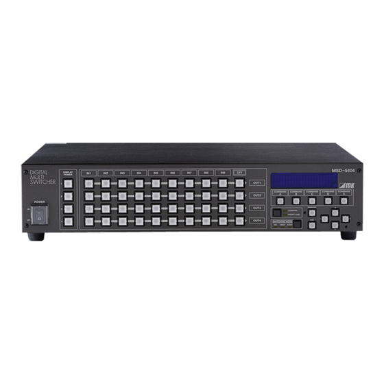
DIGITAL
DISPLAY
POWER
MULTI
SWITCHER
1
2
POWER
3
ON
OFF
4
●Thank you for choosing our presentation switcher.
●To ensure the best performance of this product, please read this User's Guide and Command Guide fully
and carefully before using your switcher and keep this manual beside the product.
IN1
IN2
IN3
IN4
IN5
IDK Corporation
MSD-54 SERIES
MSD-5401 / MSD-5402 / MSD-5403 / MSD-5404
IN6
IN7
IN8
IN9
OFF
Presentation Switcher
MSD-5401SL / MSD-5402SL
<User's Guide>
OUT1
COMMAND
COMMAND
COMMAND
COMMAND
A
B
C
D
OUT2
OUT3
MENU/SET
COMMAND
PRESET LOAD
OUT4
ESC
SWITCHING MODE
V&A
VIDEO
AUDIO
Ver. 1.0.3
MSD-5404
COMMAND
E
Advertisement
Table of Contents


Need help?
Do you have a question about the MSD-5401 and is the answer not in the manual?
Questions and answers