Table of Contents
Advertisement
Quick Links
LPOD
Outdoor Amplifier / Block Up Converter (BUC)
Installation and Operation Manual
For Firmware Ver. 1.5.6 or Higher
Part Number MN-LPOD / CD-LPOD
Revision 14
IMPORTANT NOTE: The information contained in this document supersedes all previously published
information regarding this product. Product specifications are subject to change without prior notice.
Part Number MN-LPOD / CD-LPOD Revision 14
Advertisement
Table of Contents

Related Manuals for Comtech EF Data LPOD PS 1.5


Summary of Contents for Comtech EF Data LPOD PS 1.5
- Page 1 LPOD Outdoor Amplifier / Block Up Converter (BUC) Installation and Operation Manual For Firmware Ver. 1.5.6 or Higher Part Number MN-LPOD / CD-LPOD Revision 14 IMPORTANT NOTE: The information contained in this document supersedes all previously published information regarding this product. Product specifications are subject to change without prior notice. Part Number MN-LPOD / CD-LPOD Revision 14...
- Page 2 Copyright © 2011 Comtech EF Data. All rights reserved. Printed in the USA. Comtech EF Data, 2114 West 7th Street, Tempe, Arizona 85281 USA, 480.333.2200, FAX: 480.333.2161...
- Page 3 Errata B for MN-LPOD Rev 14 Comtech EF Data Documentation Update Subject: Revise Table 1.5.1 to add new model characteristics, 950-1450 MHz, 12.75-13.25 GHz Errata Part Number: ER-LPOD-EB14 (Errata documents are not revised) PLM CO Number: C-0036842 Comments: See attached page(s). The new information will be included in the next released revision of the manual.
- Page 4 ER-LPOD-EB14 Rev - PLM C-0036842...
- Page 5 Errata A Comtech EF Data Documentation Update Subject: Revise Chapter 3 Sect. 3.4.2 “Steps to FTP Upload the Firmware Files” Step 3e source and destination filenames. Original Manual Part Number/Rev: MN‐LPOD Rev 14 Errata Number/ PLM Document ID: ER‐LPOD‐EA14 REV ‐ PLM CO Number: C‐0035915 Comments: The updated information will be incorporated into the next formal revision of the manual: Revise Step 3e in Sect. 3.4.2 to read: ER‐LPOD‐EA14 REV ‐ THIS DOCUMENT IS NOT SUBJECT TO REVISION/UPDATE! PLM CO C‐0035915 Page 1 of 2...
- Page 6 Errata A for MN‐LPOD Rev 14 Revise “Chapter 3 Sect. 3.4.2 Steps to FTP Upload the Firmware Files” Step 3e filenames BLANK PAGE ER‐LPOD‐EA14 REV ‐ THIS DOCUMENT IS NOT SUBJECT TO REVISION/UPDATE! PLM CO C‐0035915 Page 2 of 2 ...
-
Page 7: Table Of Contents
Safety and Compliance ................. xvii Electrical Safety and Compliance ..............xvii Installation Guidelines Regarding Power Line Quality ........xvii Product Support ..................xviii Comtech EF Data Headquarters ..............xviii Warranty Policy ..................... xix Limitations of Warranty ..................xix Exclusive Remedies ..................... xx CHAPTER 1. - Page 8 1.5.4 Environmental ..................1–12 1.5.5 Physical ....................1–13 Dimensional Envelopes ..............1–14 1.6.1 LPOD PS 1 Dimensional Envelopes............. 1–15 1.6.2 LPOD PS 1.5 Dimensional Envelopes..........1–21 1.6.3 LPOD PS 2 Dimensional Envelopes............. 1–25 CHAPTER 2. SYSTEM CONNECTORS, INSTALLATION, AND STARTUP ..................
-
Page 9: Table Of Contents
2.3.4.1 LPOD PS 1 ‘J3 | POWER IN’ DC Power Main ......2–7 2.3.4.2 LPOD PS 1.5 ‘J3 | POWER IN’ DC Power Main ......2–8 2.3.4.3 LPOD PS 2 ‘J3 | POWER IN’ DC Power Main ......2–8 2.3.4.4 LPOD PS 2 ‘J3 | POWER IN’... - Page 10 LPOD C-, X-, or Ku-Band Outdoor Amplifier / Block Up Converter (BUC) MN-LPOD / CD-LPOD Table of Contents Revision 14 3.2.3.1 Use the HTTP Interface to Find the Firmware Information ..3–5 3.2.3.2 Use the Serial Interface to Find the Firmware Information ..3–6 3.2.4 Make a Temporary Folder (Subdirectory) on the User PC ....
- Page 11 LPOD C-, X-, or Ku-Band Outdoor Amplifier / Block Up Converter (BUC) MN-LPOD / CD-LPOD Table of Contents Revision 14 4.4.3.1 Menu Tree ................4–11 4.4.3.2 Page Navigation ............... 4–11 4.4.3.3 Page Sections ................4–11 4.4.3.4 Action Buttons ................. 4–12 4.4.3.5 Drop-down Lists ...............
- Page 12 1:1 Redundancy System Assembly Kit Examples....... A–12 A.4.1 Common Kit Examples ............... A–13 A.4.2 LPOD PS 1 1:1 Redundancy Kit Examples .......... A–28 A.4.3 LPOD PS 1.5 1:1 Redundancy Kit Examples ........A–44 A.4.4 LPOD PS 2 1:1 Redundancy Kit Examples .......... A–52 viii...
-
Page 13: Tables
Table 2-3. LPOD PS 2 ‘J3 | POWER IN’ Pin Assignments ........2–6 Table 2-4. LPOD PS 1 ‘J3 | POWER IN’ Pin Assignments ........2–7 Table 2-5. LPOD PS 1.5 ‘J3 | POWER IN’ Pin Assignments ........2–8 Table 2-6. LPOD PS 2 ‘J3 | POWER IN’ Pin Assignments ........2–8 Table 2-7. -
Page 14: Figures
Table A-9. Parts List for KT-0020526 LPOD PS 1.5 C-Band DC Option 1:1 Redundancy Kit ..................A–44 Table A-10. Parts List for KT-0000060 LPOD PS 1.5 Ku-Band 1:1 Redundancy Kit ........................A–48 Table A-11. Parts List for KT-0000091 LPOD PS 2 C-Band 1:1 Redundancy Kit ........................ - Page 15 LPOD C-, X-, or Ku-Band Outdoor Amplifier / Block Up Converter (BUC) MN-LPOD / CD-LPOD Table of Contents Revision 14 Figure 2-3. LPOD PS 2 Connectors ..............2–3 Figure 2-4. Circular Connector Example ............2–11 Figure 2-5. LPOD ‘J10 | Modem Rx’ and ‘J11 | LNB’ Connectors ..... 2–12 Figure 2-6.
- Page 16 Figure A-19. KT-0000170 LPOD PS 1 X-Band 1:1 Redundancy Kit Example – Assembled Isometric View ................ A–42 Figure A-20. KT-0020526 LPOD PS 1.5 C-Band DC Option 1:1 Redundancy Kit Example – Exploded Isometric Views, Steps 1 & 2 ........A–45 Figure A-21.
- Page 17 MN-LPOD / CD-LPOD Table of Contents Revision 14 Figure A-24. KT-0000060 LPOD PS 1.5 Ku-Band 1:1 Redundancy Kit Example – Assembled Isometric View ................ A–50 Figure A-25. PS 2 C-Band 1:1 Redundancy Free Standing Kit Example Using KT- 0020827 – Assembled Isometric View ............A–52 Figure A-26.
- Page 18 LPOD C-, X-, or Ku-Band Outdoor Amplifier / Block Up Converter (BUC) MN-LPOD / CD-LPOD Table of Contents Revision 14 Figure C-16. LPOD PS 2 Heat Sink Locations ............. C–12 Figure C-17. Reconnect the Fan 1 / Fan 2 Power Supplies ....... C–13...
-
Page 19: Preface
Further, Comtech EF Data reserves the right to make changes in the specifications of the products described in this manual at any time without notice and without... -
Page 20: Conventions And References
Patents and Trademarks See all of Comtech EF Data's Patents and Patents Pending at http://patents.comtechefdata.com. Comtech EF Data acknowledges that all trademarks are the property of the trademark owners. Warnings, Cautions, Notes, and References A WARNING indicates a potentially hazardous situation that, if not avoided, could result in death or serious injury. -
Page 21: Recommended Standard Designations
• Be familiar with the warnings presented in this manual. Installation Guidelines Regarding Power Line Quality Comtech EF Data has become familiar with the varying quality of the AC power grid around the world. Observing the following installation guidelines should help ensure a reliable installation. -
Page 22: Product Support
LPOD’s power supply. However, if the installation will be in an area with a high probability of lightning strikes, Comtech EF Data recommends the installation of surge suppression on the RF and IF cables. One source of these suppressors is PolyPhaser (www.polyphaser.com). -
Page 23: Warranty Policy
The warranty does not apply to any part of a product that has been installed, altered, repaired, or misused in any way that, in the opinion of Comtech EF Data Corporation, would affect the reliability or detracts from the performance of any... -
Page 24: Exclusive Remedies
The remedies provided herein are the buyer’s sole and exclusive remedies. Comtech EF Data shall not be liable for any direct, indirect, special, incidental, or consequential damages, whether based on contract, tort, or any other legal... -
Page 25: Chapter 1. Introduction
Chapter 1. INTRODUCTION 1.1 Overview Comtech EF Data’s LPOD family of Outdoor Amplifiers / Block Up Converters (BUCs) – referred to collectively throughout this manual as the LPOD – deliver their rated power, guaranteed, to the transmit waveguide flange at the 1 dB compression point. -
Page 26: Functional Description
As shown in Figure 1-1, Comtech EF Data’s LPOD is available in three models: the PS 1, PS 1.5 and PS 2. Each LPOD consists of a CEFD SSPA module with the Monitor/Control Processor (MCP), a power supply, and a fan assembly. -
Page 27: Built-In Redundancy Controller
1.3.4 “Smart BUC” Functionality Comtech EF Data’s unique approach to L-Band/RF frequency conversions eliminates DC and 10 MHz from the input coax. This simplifies redundant and multi-carrier operation. Full 13.75 to 14.5 GHz Ku coverage and 5850 to 6725... -
Page 28: Optional Internal 10 Mhz Reference
LPOD C-, X-, or Ku-Band Outdoor Amplifier / Block Up Converter (BUC) MN-LPOD Introduction Revision 14 user can quickly gather intelligence not only about the unit itself, but also the unit’s operational environment. 1.3.6 Optional Internal 10 MHz Reference With the optional high stability, oven-controlled crystal oscillator (OCXO) installed, one more signal is removed from the TX IF cable. -
Page 29: Figure 1-2. Lpod Ps 1/1.5 Block Diagram
LPOD C-, X-, or Ku-Band Outdoor Amplifier / Block Up Converter (BUC) MN-LPOD Introduction Revision 14 Figure 1-2. LPOD PS 1/1.5 Block Diagram 1–5... -
Page 30: Figure 1-3. Lpod Ps 2 Block Diagram
LPOD C-, X-, or Ku-Band Outdoor Amplifier / Block Up Converter (BUC) MN-LPOD Introduction Revision 14 Figure 1-3. LPOD PS 2 Block Diagram 1–6... -
Page 31: Sspa Module
LPOD C-, X-, or Ku-Band Outdoor Amplifier / Block Up Converter (BUC) MN-LPOD Introduction Revision 14 1.4.2 SSPA Module The amplifier module performs the core function of the unit. An isolator is at the RF input to ensure good voltage standing wave ratio (VSWR). The RF signal then passes through an electronically controlled attenuator that adjusts the overall attenuation according to the user input. -
Page 32: Lnb Operation
LPOD C-, X-, or Ku-Band Outdoor Amplifier / Block Up Converter (BUC) MN-LPOD Introduction Revision 14 • The +5.8V, -5.8V, +7.8V and +13.5V outputs are used to operate the M&C board and other overhead functions. 1.4.5 LNB Operation Either LPOD package style may be ordered with an optional internal 10MHz reference and Low Noise Block (LNB) converter bias tee. - Page 33 LPOD C-, X-, or Ku-Band Outdoor Amplifier / Block Up Converter (BUC) MN-LPOD Introduction Revision 14 The unit is capable of EIA-232, EIA-485, or Ethernet remote communication. A discrete mute control and relay status output is also available. The M&C system monitors the fan speed (PS 2 only), unit temperature, all power supply voltages, power transistor currents, output power, etc.
-
Page 34: Summary Of Specifications
LPOD C-, X-, or Ku-Band Outdoor Amplifier / Block Up Converter (BUC) MN-LPOD Introduction Revision 14 1.5 Summary of Specifications 1.5.1 Characteristics Note 1 IF Input Frequency RF Output Frequency 950 – 1525 MHz 5.850 – 6.425 GHz 950 – 1750 MHz 5.850 –... - Page 35 LPOD C-, X-, or Ku-Band Outdoor Amplifier / Block Up Converter (BUC) MN-LPOD Introduction Revision 14 Gain Min (Typical) 70 (75 dB) 90-264 VAC, 47-63 Hz, Power Factor Corrected, Input Power Supply Requirements .96 (typical) (48 VDC optional) Max IF Input level (no damage) +10 dBm Gain Adjust 20 dB in 0.25 dB steps...
-
Page 36: Optional Internal Reference
LPOD C-, X-, or Ku-Band Outdoor Amplifier / Block Up Converter (BUC) MN-LPOD Introduction Revision 14 Phase Noise (dBc/Hz) (with optional internal or equivalent performance Typical (C/X/Ku) dBc/Hz Spec (C/X/Ku) dBc/Hz external reference) 100 Hz -79/-78/-76 -72/-72/-69 1 KHz -91/-87/-85 -84/-84/-82 Offset 10 KHz... -
Page 37: Physical
LPOD C-, X-, or Ku-Band Outdoor Amplifier / Block Up Converter (BUC) MN-LPOD Introduction Revision 14 1.5.5 Physical PS 1, 1.5 17 lbs. (9.1 kg) Nominal Weight PS 2 47 lbs (21.32 kg) Nominal 12.65 x 6.26 x 7.37 in. Dimensions PS 1 (321.3 x 159 x 187.2 mm) -
Page 38: Dimensional Envelopes
PS 1 X-Band PS 1 Ku-Band PS 1 Ku-Band – Reduced Height Unit 1-10 PS 1.5 C-Band (DC Option) 1-11 PS 1.5 C-Band (AC Option) 1.6.2 LPOD PS 1.5 1-12 PS 1.5 X-Band 1-13 PS 1.5 Ku-Band 1-14 PS 2 C-Band 1.6.1 LPOD PS 2... -
Page 39: Lpod Ps 1 Dimensional Envelopes
LPOD C-, X-, or Ku-Band Outdoor Amplifier / Block Up Converter (BUC) MN-LPOD Introduction Revision 14 1.6.1 LPOD PS 1 Dimensional Envelopes Figure 1-4. LPOD PS 1 C-Band Dimensional Envelope (Coax Output) 1–15... -
Page 40: Figure 1-5. Lpod Ps 1 C-Band Dimensional Envelope (Coax Output) - Reduced
LPOD C-, X-, or Ku-Band Outdoor Amplifier / Block Up Converter (BUC) MN-LPOD Introduction Revision 14 Figure 1-5. LPOD PS 1 C-Band Dimensional Envelope (Coax Output) – Reduced Height Unit 1–16... -
Page 41: Figure 1-6. Lpod Ps 1 C-Band Dimensional Envelope
LPOD C-, X-, or Ku-Band Outdoor Amplifier / Block Up Converter (BUC) MN-LPOD Introduction Revision 14 Figure 1-6. LPOD PS 1 C-Band Dimensional Envelope 1–17... -
Page 42: Figure 1-7. Lpod Ps 1 X-Band Dimensional Envelope
LPOD C-, X-, or Ku-Band Outdoor Amplifier / Block Up Converter (BUC) MN-LPOD Introduction Revision 14 Figure 1-7. LPOD PS 1 X-Band Dimensional Envelope 1–18... -
Page 43: Figure 1-8. Lpod Ps 1 Ku-Band Dimensional Envelope
LPOD C-, X-, or Ku-Band Outdoor Amplifier / Block Up Converter (BUC) MN-LPOD Introduction Revision 14 Figure 1-8. LPOD PS 1 Ku-Band Dimensional Envelope 1–19... -
Page 44: Figure 1-9. Lpod Ps 1 Ku-Band Dimensional Envelope - Reduced Height Unit
LPOD C-, X-, or Ku-Band Outdoor Amplifier / Block Up Converter (BUC) MN-LPOD Introduction Revision 14 Figure 1-9. LPOD PS 1 Ku-Band Dimensional Envelope – Reduced Height Unit 1–20... -
Page 45: Lpod Ps 1.5 Dimensional Envelopes
LPOD C-, X-, or Ku-Band Outdoor Amplifier / Block Up Converter (BUC) MN-LPOD Introduction Revision 14 1.6.2 LPOD PS 1.5 Dimensional Envelopes Figure 1-10. LPOD PS 1.5 C-Band Dimensional Envelope (DC Option) 1–21... -
Page 46: Figure 1-11. Lpod Ps 1.5 C-Band Dimensional Envelope (Ac Option)
LPOD C-, X-, or Ku-Band Outdoor Amplifier / Block Up Converter (BUC) MN-LPOD Introduction Revision 14 Figure 1-11. LPOD PS 1.5 C-Band Dimensional Envelope (AC Option) 1–22... -
Page 47: Figure 1-12. Lpod Ps 1.5 X-Band Dimensional Envelope
LPOD C-, X-, or Ku-Band Outdoor Amplifier / Block Up Converter (BUC) MN-LPOD Introduction Revision 14 Figure 1-12. LPOD PS 1.5 X-Band Dimensional Envelope 1–23... -
Page 48: Figure 1-13. Lpod Ps 1.5 Ku-Band Dimensional Envelope
LPOD C-, X-, or Ku-Band Outdoor Amplifier / Block Up Converter (BUC) MN-LPOD Introduction Revision 14 Figure 1-13. LPOD PS 1.5 Ku-Band Dimensional Envelope 1–24... -
Page 49: Lpod Ps 2 Dimensional Envelopes
LPOD C-, X-, or Ku-Band Outdoor Amplifier / Block Up Converter (BUC) MN-LPOD Introduction Revision 14 1.6.3 LPOD PS 2 Dimensional Envelopes Figure 1-14. LPOD PS 2 C-Band Dimensional Envelope 1–25... -
Page 50: Figure 1-15. Lpod Ps 2 X-Band Dimensional Envelope
LPOD C-, X-, or Ku-Band Outdoor Amplifier / Block Up Converter (BUC) MN-LPOD Introduction Revision 14 Figure 1-15. LPOD PS 2 X-Band Dimensional Envelope 1–26... -
Page 51: Figure 1-16. Lpod Ps 2 Ku-Band Dimensional Envelope
LPOD C-, X-, or Ku-Band Outdoor Amplifier / Block Up Converter (BUC) MN-LPOD Introduction Revision 14 Figure 1-16. LPOD PS 2 Ku-Band Dimensional Envelope 1–27... - Page 52 LPOD C-, X-, or Ku-Band Outdoor Amplifier / Block Up Converter (BUC) MN-LPOD Introduction Revision 14 Notes: 1–28...
- Page 53 Chapter 2. SYSTEM CONNECTORS, A ND INSTALLATION, STARTUP 2.1 Overview • See Chapter 4. ETHERNET INTERFACE OPERATION for information about using the LPOD’s remote Ethernet M&C functionality. • See Chapter 5. SERIAL INTERFACE OPERATION for information about using serial-based remote commands and queries. •...
-
Page 54: Chapter 2. System Connectors, Installation, And Startup
Should you receive an accessory kit that contains only the mating cable connectors, or if you (the end-user) choose to supply your own cables and connectors, Comtech EF Data strongly recommends that you use an adhesive lined heatshrink such as TE Connectivity #ATUM-24/6-0 (or equivalent) to cover the connector strain-relief area. -
Page 55: Lpod Interface Connectors
The LPOD external connectors provide all necessary connections between the LPOD PS 1 (Figure 2-1), PS 1.5 (Figure 2-2), or PS 2 (Figure 2-3) models and other equipment. Figure 2-1. LPOD PS 1 Connectors Figure 2-2. LPOD PS 1.5 Connectors Figure 2-3. LPOD PS 2 Connectors 2–3... -
Page 56: Connector 'J1 | Lband In' Or 'J1 | Tx In
LPOD C-, X-, or Ku-Band Outdoor Amplifier / Block Up Converter (BUC) MN-LPOD System Connectors, Installation, and Startup Revision 14 2.3.1 Connector ‘J1 | LBAND IN’ or ‘J1 | Tx IN’ The RF input connector is a Type ‘N’ female connector. -
Page 57: Connector 'J3 | Power In' Ac Power Mains
LPOD C-, X-, or Ku-Band Outdoor Amplifier / Block Up Converter (BUC) MN-LPOD System Connectors, Installation, and Startup Revision 14 2.3.3 Connector ‘J3 | POWER IN’ AC Power Mains WARNING! FOR SAFETY REASONS, MAKE SURE YOU KNOW THAT THE ‘J3 | POWER IN’... -
Page 58: Lpod Ps 1, Ps 1.5 'J3 | Power In' Ac Power Main
LPOD C-, X-, or Ku-Band Outdoor Amplifier / Block Up Converter (BUC) MN-LPOD System Connectors, Installation, and Startup Revision 14 2.3.3.1 LPOD PS 1, PS 1.5 ‘J3 | POWER IN’ AC Power Main The mating connector specification and pin assignments specific to the LPOD PS 1 and PS 1.5 AC power interfaces are as follows: Mating Connector: CEFD P/N CN/MS-STPG03F02 (ITT Cannon KPT06B-12-35) -
Page 59: Connector 'J3 | Power In' Dc Power Mains
LPOD C-, X-, or Ku-Band Outdoor Amplifier / Block Up Converter (BUC) MN-LPOD System Connectors, Installation, and Startup Revision 14 2.3.4 Connector ‘J3 | POWER IN’ DC Power Mains WARNING! FOR SAFETY REASONS, MAKE SURE YOU KNOW THAT THE ‘J3 | POWER IN’... -
Page 60: Lpod Ps 1.5 'J3 | Power In' Dc Power Main
Revision 14 2.3.4.2 LPOD PS 1.5 ‘J3 | POWER IN’ DC Power Main The mating connector specification and the pin assignments specific to the LPOD PS 1.5 DC power interface are as follows: Mating Connector: CEFD P/N CN-0020517 (MS3116E-14-5S(476), Amphenol PT06E-14- 5S(476)) Table 2-5. -
Page 61: Table 2-7. Lpod Ps 2 'J3 | Power In' 48Vdc Pin Assignments
LPOD C-, X-, or Ku-Band Outdoor Amplifier / Block Up Converter (BUC) MN-LPOD System Connectors, Installation, and Startup Revision 14 2.3.4.4 LPOD PS 2 ‘J3 | POWER IN’ 48VDC Power Main Option The connector type and mating connector specification and the pin assignments specific to the LPOD PS 2 48VDC power interface option are as follows: Unit Connector Type: CEFD P/N CN-0000288 (ITT Cannon CA3102E20-15SB-F80A232) -
Page 62: Connector 'J6 | Com1' (Remote Communications And Discrete Control Port)
LPOD C-, X-, or Ku-Band Outdoor Amplifier / Block Up Converter (BUC) MN-LPOD System Connectors, Installation, and Startup Revision 14 2.3.5 Connector ‘J6 | COM1’ (Remote Communications and Discrete Control Port) The ‘J6 | COM 1’ discrete control connector is the primary input for controlling and monitoring the LPOD. -
Page 63: About Circular Connectors
LPOD C-, X-, or Ku-Band Outdoor Amplifier / Block Up Converter (BUC) MN-LPOD System Connectors, Installation, and Startup Revision 14 2.3.5.1 About Circular Connectors The connector pairs (Figure 2-4) feature a sleeve lock configuration, with an array of pins (male side) coupled to mating sockets (female side). Feature Description Primary Alignment features... -
Page 64: Connector 'J9 | Output Sample' (Ps 2 Only)
LPOD C-, X-, or Ku-Band Outdoor Amplifier / Block Up Converter (BUC) MN-LPOD System Connectors, Installation, and Startup Revision 14 2.3.6 Connector ‘J9 | OUTPUT SAMPLE’ (PS 2 ONLY) The ‘J9 | OUTPUT SAMPLE’ port is a Type ‘N’ female connector available only on the PS 2 model. It provides a nominal -40 dB sample of the output signal. -
Page 65: Ground Connector
LPOD C-, X-, or Ku-Band Outdoor Amplifier / Block Up Converter (BUC) MN-LPOD System Connectors, Installation, and Startup Revision 14 2.3.8 Ground Connector Use this #10-32 stud, available where shown in Figure 2-6, to connect a common chassis ground among equipment. Figure 2-6. -
Page 66: Lpod Standalone (Single-Thread) Installations
(1) LPOD unit, whereas a 1:1 Redundancy System employs two (2) LPODs operating in redundancy. Several kits are available from Comtech EF Data to mount and install standalone or 1:1 Redundancy LPODs, depending on the LPOD unit ordered: • See Sect. 2.4.3 for standalone assembly and installation information for pole-mounted LPOD configurations. -
Page 67: Pole-Mounted Installations
LPOD C-, X-, or Ku-Band Outdoor Amplifier / Block Up Converter (BUC) MN-LPOD System Connectors, Installation, and Startup Revision 14 2.4.3 Pole-Mounted Installations The Universal Pole Mount Kit PL/12319-1 is used in combination with pole- mounted standalone and 1:1 Redundant LPOD installation kits. For the purpose of brevity, all further reference to this kit’s usage –... -
Page 68: Pl/12319-1 Universal Pole Mounting Kit
LPOD C-, X-, or Ku-Band Outdoor Amplifier / Block Up Converter (BUC) MN-LPOD System Connectors, Installation, and Startup Revision 14 2.4.3.1 PL/12319-1 Universal Pole Mounting Kit This kit accommodates a pole diameter of up to 13.00” (33.02 cm) OD maximum. ITEM CEFD PART NO. - Page 69 LPOD C-, X-, or Ku-Band Outdoor Amplifier / Block Up Converter (BUC) MN-LPOD System Connectors, Installation, and Startup Revision 14 Do these steps to install each kit: 1. Place the Unistrut (Item 1, part of the LPOD Mounting Kit) on a flat surface.
-
Page 70: Figure 2-8. Universal Pole Mounting Kit – Final Assembly
LPOD C-, X-, or Ku-Band Outdoor Amplifier / Block Up Converter (BUC) MN-LPOD System Connectors, Installation, and Startup Revision 14 The assembled kit appears as shown in the top and side view example shown in Figure 2-8. Depending on the application, you may proceed to the next phase of installation. -
Page 71: Kt-0000095 Single Unit Mounting Kit (Lpod Ps 1, Ps 1.5)
LPOD C-, X-, or Ku-Band Outdoor Amplifier / Block Up Converter (BUC) MN-LPOD System Connectors, Installation, and Startup Revision 14 2.4.3.2 KT-0000095 Single Unit Mounting Kit (LPOD PS 1, PS 1.5) Use this kit in combination with the PL/12319-1 Universal Pole Mounting Kit. KT-0000095 LPOD PS 1, PS 1.5 Single Unit Mounting Kit ITEM CEFD PART NO. -
Page 72: Kt-0000125 Single Unit Mounting Kit (Lpod Ps 2)
LPOD C-, X-, or Ku-Band Outdoor Amplifier / Block Up Converter (BUC) MN-LPOD System Connectors, Installation, and Startup Revision 14 2.4.3.3 KT-0000125 Single Unit Mounting Kit (LPOD PS 2) Use this kit in combination with the PL/12319-1 Universal Pole Mounting Kit. KT-0000125 LPOD PS 2 Single Unit Mounting Kit ITEM CEFD PART NO. -
Page 73: Spar-Mounted Installations (Lpod Ps 1, Ps 1.5)
LPOD PS 1 and PS 1.5 standalone configurations, in addition to satellite dish support pole mounted installations, may be installed on the antenna spar. Figure 2-11 shows a typical Comtech EF Data spar mount SSPA installation. The kit that is required for the installation of your LPOD system (Figure 2-12) is determined by the spar that is used by the antenna’s manufacturer. -
Page 74: Figure 2-12. Lpod Ps 1, Ps 1.5 Spar Mount Installation Kits
LPOD C-, X-, or Ku-Band Outdoor Amplifier / Block Up Converter (BUC) MN-LPOD System Connectors, Installation, and Startup Revision 14 LPOD SPAR MOUNT INSTALLATION KITS CEFD KIT / QTY REQ’D DESCRIPTION ITEM CEFD P/N [dim in mm] 0000083 0000084 0000085 0000289 BRACKET, MOUNTING, –... -
Page 75: Shelf-Mounted Installations (Lpod Ps 2)
LPOD C-, X-, or Ku-Band Outdoor Amplifier / Block Up Converter (BUC) MN-LPOD System Connectors, Installation, and Startup Revision 14 2.4.5 Shelf-Mounted Installations (LPOD PS 2) KT-0020524 LPOD PS 2 Single Unit Shelf Style Mounting Kit ITEM CEFD PART NO. DESCRIPTION FP-0020545 BRACKET, MOUNTING... -
Page 76: Set The Lpod Power On
LPOD C-, X-, or Ku-Band Outdoor Amplifier / Block Up Converter (BUC) MN-LPOD System Connectors, Installation, and Startup Revision 14 2.5 Set the LPOD Power ON WARNING! FOR SAFETY REASONS, NEVER TURN THE UNIT ON WITHOUT PROPER WAVEGUIDE TERMINATION ON THE ‘J2 | RF OUT’ PORT. YOU MAY OTHERWISE BE EXPOSED TO DANGEROUSLY HIGH ELECTROMAGNETIC LEVELS. -
Page 77: Chapter 3. Firmware Update
(M&C) of the LPOD. 2. Use an adapter cable to directly connect the LPOD ‘J6 | COM1’ receptacle to the serial port of the User PC. You may also use Comtech EF Data’s optional CLC-10 Handheld Terminal (left) for Remote Monitor and Control (M&C) over the Serial Interface. -
Page 78: About Firmware Numbers, File Versions, And Formats
3.1.2 About Firmware Numbers, File Versions, and Formats The Comtech EF Data Web site catalogues its firmware update archive files by product type (e.g., router, modem, etc.), the specific model, and optional hardware configurations. The LPOD files are provided under “Home | Support | Software Downloads | Amplifier Software... -
Page 79: Lpod Connections
LPOD C-, X-, or Ku-Band Outdoor Amplifier / Block Up Converter (BUC) MN-LPOD Firmware Update Revision 14 3.2.1.1 LPOD Connections For SERIAL connections, see Figure 3-1. Your connection may consist of either a user-fabricated adapter cable connecting the LPOD to the User PC serial port or, as this example shows, use of the optional CLC-10 Handheld Terminal (part of the CEFD KT-0020518 M&C Accessory Kit). -
Page 80: Configure The Terminal Emulator Program
LPOD C-, X-, or Ku-Band Outdoor Amplifier / Block Up Converter (BUC) MN-LPOD Firmware Update Revision 14 Figure 3-2. Standalone or Redundant Ethernet Connection 3.2.2 Configure the Terminal Emulator Program On the User PC – Open the terminal emulator program, and then configure the program’s serial port communication and terminal display operation: •... -
Page 81: Get The Lpod Management Ip Address And Firmware Information
LPOD C-, X-, or Ku-Band Outdoor Amplifier / Block Up Converter (BUC) MN-LPOD Firmware Update Revision 14 • Port Flow Control = NONE • Display New Line Rx/Tx = CR Read your terminal emulator program user guide or HELP feature for operating and configuration instructions. -
Page 82: Use The Serial Interface To Find The Firmware Information
“Next Reboot Image”, as shown in this example: 2. Write down your firmware information for further reference or to provide to Comtech EF Data Product support. 3.2.3.2 Use the Serial Interface to Find the Firmware Information Chapter 5. SERIAL INTERFACE OPERATION Use your terminal emulator program or CLC-10 to execute remote queries with the LPOD. -
Page 83: Make A Temporary Folder (Subdirectory) On The User Pc
LPOD C-, X-, or Ku-Band Outdoor Amplifier / Block Up Converter (BUC) MN-LPOD Firmware Update Revision 14 3.2.4 Make a Temporary Folder (Subdirectory) on the User PC The temporary folder is where you store the firmware archive download. There are several ways you can make a temporary folder on a Windows PC: •... -
Page 84: Use Windows Explorer To Make A Folder
LPOD C-, X-, or Ku-Band Outdoor Amplifier / Block Up Converter (BUC) MN-LPOD Firmware Update Revision 14 3.2.4.2 Use Windows Explorer to Make a Folder Do these steps: 1. Left-double-click the Windows Explorer icon on the Windows Desktop. 2. Depending in your Windows OS version: select File > New > Folder, or click your Folder Destination (e.g., Windows (C:) and then New Folder to make the new, temporary folder in the active location. -
Page 85: Use Windows Command-Line Or Command Prompt To Make A Folder
LPOD C-, X-, or Ku-Band Outdoor Amplifier / Block Up Converter (BUC) MN-LPOD Firmware Update Revision 14 3.2.4.4 Use Windows Command-line or Command Prompt to Make a Folder Select Start on the Windows taskbar and then do these steps: 1. Click Run... to open the Run window (or, depending on Windows OS version prior to Windows 95, click the MS-DOS Prompt icon from the Main Menu). -
Page 86: Download And Extract The Firmware Update Files
LPOD C-, X-, or Ku-Band Outdoor Amplifier / Block Up Converter (BUC) MN-LPOD Firmware Update Revision 14 3.3 Download and Extract the Firmware Update Files Do these steps: 1. Go online to www.comtechefdata.com. 2. On the Main page – Under Support Information or the Support tab, select the Software Downloads hyperlink. - Page 87 LPOD C-, X-, or Ku-Band Outdoor Amplifier / Block Up Converter (BUC) MN-LPOD Firmware Update Revision 14 o Click [Save] to download the EXE file to your Downloads folder. Once the download is complete the dialogue prompts you to either [Run] the self-extracting file, or to open or view the Windows Downloads folder for further action.
-
Page 88: Use Windows Desktop To View Folder Contents
LPOD C-, X-, or Ku-Band Outdoor Amplifier / Block Up Converter (BUC) MN-LPOD Firmware Update Revision 14 • To use Windows Command-line or Command Prompt, see Section 3.3.1.2. After you confirm the firmware files are in the folder, proceed to Section 3.4 to upload the firmware update to the LPOD. -
Page 89: Steps To Ftp Upload The Firmware Files
LPOD C-, X-, or Ku-Band Outdoor Amplifier / Block Up Converter (BUC) MN-LPOD Firmware Update Revision 14 • You download or otherwise have Comtech’s latest firmware files available on the User PC in an accessible temporary folder. • OPTIONAL: You download or otherwise have Comtech’s “CReflash” utility available on the User PC in an accessible temporary folder. -
Page 90: Optional: Steps To "Creflash" Upload The Firmware Files
The “CReflash” utility is available on request from Comtech EF Data Product Support. Do these steps: 1. You must obtain the CReflash utility (CReflash.exe) from Comtech EF Data. Make sure to place the application into the temporary folder that you created for the firmware update process (or some other easy-to- remember location, e.g., the Windows Desktop). -
Page 91: Steps To Update The Lpod Unit
LPOD C-, X-, or Ku-Band Outdoor Amplifier / Block Up Converter (BUC) MN-LPOD Firmware Update Revision 14 3.4.4 Steps to Update the LPOD Unit Chapter 4. ETHERNET INTERFACE OPERATION Use the LPOD HTTP Interface to select the new firmware and soft-reboot the unit. - Page 92 LPOD C-, X-, or Ku-Band Outdoor Amplifier / Block Up Converter (BUC) MN-LPOD Firmware Update Revision 14 Notes: 3–16...
-
Page 93: Chapter 4. Ethernet Interface Operation
Network Monitoring System (NMS) and a user-supplied Management Information Base (MIB) File Browser. CAUTION Comtech EF Data recommends use of the Ethernet-based SNMP interface for advanced users only. All other users are strongly encouraged to use the LPOD HTTP Interface for remote Monitor and Control (M&C) of the LPOD. -
Page 94: Snmp Interface
In these LPOD MIB file names, the letter x represents the revision of the file. 4.2.1.1 ComtechEFData Root MIB file • FW-0000291x.mib • ComtechEFData MIB file gives the root tree for all Comtech EF Data LPOD products (PSx) and consists of only the following OID: o Name: comtechEFData o Type: MODULE-IDENTITY o OID: 1.3.6.1.4.1.6247... -
Page 95: Lpod Mib File
LPOD C-, X-, or Ku-Band Outdoor Amplifier / Block Up Converter (BUC) MN-LPOD Ethernet Interface Operation Revision 14 4.2.1.2 LPOD MIB file • FW-0000289x.mib • MIB file consists of all of the OID’s for management of the LPOD functions 4.2.1.3 LPOD Traps MIB file •... - Page 96 LPOD C-, X-, or Ku-Band Outdoor Amplifier / Block Up Converter (BUC) MN-LPOD Ethernet Interface Operation Revision 14 The LPOD supports the following MIB2 SNMPv1 traps and v2 notifications: MIB2 SNMPv1 trap: Authentication Failure MIB2 SNMPv2 notifications: Authentication Failure 1.3.6.1.6.3.1.1.5.5 The LPOD supports the following Faults SNMPv1 traps and v2 notifications: Faults SNMPv1 traps: lpodPowerSupply24V1StatusV1...
- Page 97 LPOD C-, X-, or Ku-Band Outdoor Amplifier / Block Up Converter (BUC) MN-LPOD Ethernet Interface Operation Revision 14 lpodLNBCSStatusV1 62474823 lpodSwitchStatusV1 62474824 Faults SNMPv2 notifications: lpodPowerSupply24V1Status 1.3.6.1.4.1.6247.48.1.3.1.1 lpodPowerSupply24V2Status 1.3.6.1.4.1.6247.48.1.3.1.2 lpodPowerSupplyLNBStatus 1.3.6.1.4.1.6247.48.1.3.1.3 lpodPowerSupply13VStatus 1.3.6.1.4.1.6247.48.1.3.1.4 lpodPowerSupply10VStatus 1.3.6.1.4.1.6247.48.1.3.1.5 lpodRFPowerSupply10V1Status 1.3.6.1.4.1.6247.48.1.3.1.6 lpodRFPowerSupply10V2Status 1.3.6.1.4.1.6247.48.1.3.1.7 lpodPowerSupply7V8TStatus 1.3.6.1.4.1.6247.48.1.3.1.8 lpodPowerSupply5V8TStatus 1.3.6.1.4.1.6247.48.1.3.1.9...
-
Page 98: Telnet Interface
LPOD C-, X-, or Ku-Band Outdoor Amplifier / Block Up Converter (BUC) MN-LPOD Ethernet Interface Operation Revision 14 4.3 Telnet Interface Chapter 5. SERIAL INTERFACE OPERATION The LPOD has a Telnet interface for the purpose of equipment M&C via the optional Serial Remote Control protocol. -
Page 99: Configure Hyperterminal For Telnet Remote Control Operation4-7
LPOD C-, X-, or Ku-Band Outdoor Amplifier / Block Up Converter (BUC) MN-LPOD Ethernet Interface Operation Revision 14 Figure 4-2. Telnet Interface Example – HyperTerminal 4.3.1.1 Configure HyperTerminal for Telnet Remote Control Operation Figure 4-3. Configure HyperTerminal See Figure 4-3. Do these steps: 1. -
Page 100: Http (Web Server) Interface
LPOD C-, X-, or Ku-Band Outdoor Amplifier / Block Up Converter (BUC) MN-LPOD Ethernet Interface Operation Revision 14 b. Enter TCP Port 23 as the “Port number”. c. Set “Connect using” to TCP/IP (Winsock) instead of COM1 or COM2. d. Click [OK] to save your settings. 2. -
Page 101: Figure 4-5. Telnet Login And Remote Command Execution
LPOD C-, X-, or Ku-Band Outdoor Amplifier / Block Up Converter (BUC) MN-LPOD Ethernet Interface Operation Revision 14 See Figure 4-5 and do these steps: 3. Enter the Telnet username and password (the default for both parameters is comtech): 4. The LRS remote command sets or returns Local or Remote state in the form x, where x=0, 1, 2, or 3: •... -
Page 102: Http Interface User Login
LPOD C-, X-, or Ku-Band Outdoor Amplifier / Block Up Converter (BUC) MN-LPOD Ethernet Interface Operation Revision 14 4.4.2 HTTP Interface User Login Do these steps: 1. From the PC, enter the default Management IP Address for the LPOD (i.e., http://192.168.1.4) into the Address area of the browser. -
Page 103: Http Interface Features
LPOD C-, X-, or Ku-Band Outdoor Amplifier / Block Up Converter (BUC) MN-LPOD Ethernet Interface Operation Revision 14 4.4.3 HTTP Interface Features 4.4.3.1 Menu Tree Home Admin Config Status Home Access Amplifier Summary Contact SNMP Status Support Utility FETs Redundancy Events Statistics Trending Graphs... -
Page 104: Action Buttons
LPOD C-, X-, or Ku-Band Outdoor Amplifier / Block Up Converter (BUC) MN-LPOD Ethernet Interface Operation Revision 14 4.4.3.4 Action Buttons Action buttons are important in the LPOD HTTP Interface. Click an action button to do one of these tasks: •... -
Page 105: Http Interface Page Examples And Descriptions
LPOD C-, X-, or Ku-Band Outdoor Amplifier / Block Up Converter (BUC) MN-LPOD Ethernet Interface Operation Revision 14 4.5 HTTP Interface Page Examples and Descriptions See Chapter 5. SERIAL INTERFACE OPERATION for detailed operating information for the configuration and monitoring features available throughout this interface. -
Page 106: Home | Contact
LPOD C-, X-, or Ku-Band Outdoor Amplifier / Block Up Converter (BUC) MN-LPOD Ethernet Interface Operation Revision 14 4.5.1.2 Home | Contact For all product support, please call: +1.240.243.1880 +1.866.472.3963 (toll free USA) Figure 4-9. ‘Home | Contact’ Page 4–14... -
Page 107: Home | Support
The Problem Report area of the display allows up to 256 characters maximum. The ‘Home | Support’ page uses Simple Mail Transport Protocol (SMTP) to send E-mail to Comtech EF Data Product Support: cdmipsupport@comtechefdata.com Once you enter the Contact Information and compose a message in the Problem Report text window, click [Submit E-mail] to send the message. -
Page 108: Admin (Administration)
LPOD C-, X-, or Ku-Band Outdoor Amplifier / Block Up Converter (BUC) MN-LPOD Ethernet Interface Operation Revision 14 4.5.2 Admin (Administration) Pages These pages are available only to users who have logged in using the Administrator Name and Password. Use these administrator pages to set up user access. Click Access or SNMP to continue. - Page 109 LPOD C-, X-, or Ku-Band Outdoor Amplifier / Block Up Converter (BUC) MN-LPOD Ethernet Interface Operation Revision 14 Click [Change IP Address] to save any changes. System Account Access Information Name fields can be any alphanumeric combination with a maximum length of 10 characters.
-
Page 110: Admin | Snmp
LPOD C-, X-, or Ku-Band Outdoor Amplifier / Block Up Converter (BUC) MN-LPOD Ethernet Interface Operation Revision 14 4.5.2.2 Admin | SNMP Click [Refresh] to see the latest page data. Figure 4-12. ‘Admin | SNMP’ Page • Simple Network Management – Use the drop-down list to select Enabled or Disabled. -
Page 111: Config
LPOD C-, X-, or Ku-Band Outdoor Amplifier / Block Up Converter (BUC) MN-LPOD Ethernet Interface Operation Revision 14 4.5.3 Config Pages Use the Configuration pages to configure all operating parameters for the LPOD. Click Amplifier, LNB, Utility, or Redundancy to continue. 4.5.3.1 Config | Amplifier Click [Refresh] to see the latest page data. - Page 112 LPOD C-, X-, or Ku-Band Outdoor Amplifier / Block Up Converter (BUC) MN-LPOD Ethernet Interface Operation Revision 14 • Attenuation Offset – Enter a valid offset value, in dB. • Fault Recovery – Use the drop-down list to select Automatic or Manual. •...
-
Page 113: Config | Lnb
LPOD C-, X-, or Ku-Band Outdoor Amplifier / Block Up Converter (BUC) MN-LPOD Ethernet Interface Operation Revision 14 4.5.3.2 Config | LNB Click [Refresh] to see the latest page data. Figure 4-14. ‘Config | LNB’ Page LNB Config • LNB Current Source – Use the drop-down list to select Disable or 18V, tone off, band 3. - Page 114 LPOD C-, X-, or Ku-Band Outdoor Amplifier / Block Up Converter (BUC) MN-LPOD Ethernet Interface Operation Revision 14 Click [Submit] to save. Calibrate LNB Current Calibrate the LNB only when it is running at nominal operating conditions. The value provided here (in mA) is intended as a reference point. The alarm upper and lower thresholds are determined by this value and the LNB current window setting.
-
Page 115: Config | Utility
LPOD C-, X-, or Ku-Band Outdoor Amplifier / Block Up Converter (BUC) MN-LPOD Ethernet Interface Operation Revision 14 4.5.3.3 Config | Utility Use this page to configure additional LPOD operating parameters. Click [Refresh] to see the latest page data. Figure 4-15. ‘Config | Utility’ Page Date and Time •... - Page 116 LPOD C-, X-, or Ku-Band Outdoor Amplifier / Block Up Converter (BUC) MN-LPOD Ethernet Interface Operation Revision 14 Click Change CID to save the change. Current Active Firmware Image: # (read-only) This read-only window shows the Current Active Firmware Image. In this example, Image 1 is the Current Active Firmware Image.
-
Page 117: Config | Redundancy
LPOD C-, X-, or Ku-Band Outdoor Amplifier / Block Up Converter (BUC) MN-LPOD Ethernet Interface Operation Revision 14 4.5.3.4 Config | Redundancy Appendix A. 1:1 REDUNDANCY Click [Refresh] to see the latest page data. Figure 4-16. ‘Config | Redundancy’ Page Enable Redundancy Switch Mode Use the drop-down list to select the Switch Mode as follows: •... -
Page 118: Status
LPOD C-, X-, or Ku-Band Outdoor Amplifier / Block Up Converter (BUC) MN-LPOD Ethernet Interface Operation Revision 14 4.5.4 Status Pages Use these pages to access to event logging, operational statistics, status, FET windows, and operational trending graphs. Click the Status tab, and then click the Summary, Status, FETs, Events, Statistics, or Trending Graphs hyperlink to continue. -
Page 119: Status | Status
LPOD C-, X-, or Ku-Band Outdoor Amplifier / Block Up Converter (BUC) MN-LPOD Ethernet Interface Operation Revision 14 o An operating parameter is changed, e.g., when a command that changes an operational value is executed successfully; o A fault condition is triggered; o A redundant switchover occurs. -
Page 120: Figure 4-19. 'Status | Fets' Page
LPOD C-, X-, or Ku-Band Outdoor Amplifier / Block Up Converter (BUC) MN-LPOD Ethernet Interface Operation Revision 14 4.5.4.3 Status | FETs Use this read-only page to monitor the current operating status of the LPOD’s Q01 through Q09 RF Power Field Effect Transistors (FETs) that are installed in the RF amplifier. -
Page 121: Status | Events
LPOD C-, X-, or Ku-Band Outdoor Amplifier / Block Up Converter (BUC) MN-LPOD Ethernet Interface Operation Revision 14 4.5.4.4 Status | Events Use this page to see stored events data. Additionally, use it to set the parameters for how the LPOD triggers events and alarms. Click [Refresh] to see the latest page data. - Page 122 LPOD C-, X-, or Ku-Band Outdoor Amplifier / Block Up Converter (BUC) MN-LPOD Ethernet Interface Operation Revision 14 Alarm Mask Use the drop-down lists to select each alarm as Fault, Alarm, or Masked for: • Low Forward RF Power • Fan Speed •...
-
Page 123: Status | Statistics
LPOD C-, X-, or Ku-Band Outdoor Amplifier / Block Up Converter (BUC) MN-LPOD Ethernet Interface Operation Revision 14 4.5.4.5 Status | Statistics This page shows all unread, stored statistics. Use it to configure how the LPOD handles and shows statistics. Click [Refresh] to see the latest page data. Figure 4-21. - Page 124 LPOD C-, X-, or Ku-Band Outdoor Amplifier / Block Up Converter (BUC) MN-LPOD Ethernet Interface Operation Revision 14 Statistics Configuration • Statistics Interval – Enter the interval at which statistics are logged. The interval is set in minutes. Minimum resolution is 1 minute (001); maximum is 99 minutes (099).
-
Page 125: Status | Trending Graphs
LPOD C-, X-, or Ku-Band Outdoor Amplifier / Block Up Converter (BUC) MN-LPOD Ethernet Interface Operation Revision 14 4.5.4.6 Status | Trending Graphs Click [Refresh] to see the latest graph data. Figure 4-22. ‘Status | Trending Graphs’ Page 4–33... - Page 126 LPOD C-, X-, or Ku-Band Outdoor Amplifier / Block Up Converter (BUC) MN-LPOD Ethernet Interface Operation Revision 14 This scrolling page provides graphs that show trends over time for the following operating parameters: • Amplifier Temperature • Amplifier Output Power •...
- Page 127 LPOD C-, X-, or Ku-Band Outdoor Amplifier / Block Up Converter (BUC) MN-LPOD Ethernet Interface Operation Revision 14 Graphs The graphs are all tied to the same ‘x’ scale so that you can more easily correlate data between the graphs. Temperature Graph As per the legend: •...
- Page 128 LPOD C-, X-, or Ku-Band Outdoor Amplifier / Block Up Converter (BUC) MN-LPOD Ethernet Interface Operation Revision 14 When you click the [Refresh] tab, the graph reverts to the default display (Unit in dBm). LNB Current Graph This graph displays the LNB current only if an LNB is connected to the system and is drawing current from the LNB current source.
- Page 129 LPOD C-, X-, or Ku-Band Outdoor Amplifier / Block Up Converter (BUC) MN-LPOD Ethernet Interface Operation Revision 14 Mute State Graph This graph displays the mute state (i.e., bias tee switch state as open = muted, or through path = unmuted) for the Tx Mute (red line) and the Rx Mute (blue line). Note that: •...
- Page 130 LPOD C-, X-, or Ku-Band Outdoor Amplifier / Block Up Converter (BUC) MN-LPOD Ethernet Interface Operation Revision 14 Minimum Fan Speed Graph This graph displays the slowest fan speed of any of the fans installed in the system. This example demonstrates the fan running at minimum, proportional, and maximum speeds.
-
Page 131: Chapter 5. Serial Interface Operation
LPOD with its latest available firmware. 5.1 Overview Serial-based remote management of Comtech EF Data’s LPOD family of Outdoor Amplifiers / Block Up Converters (BUCs) is available using the ‘J6 | COM1’ port. This chapter summarizes key parameters and procedures and their associated remote commands and queries, and provides detailed instructions for use of the optional serial remote control commands and queries interface. -
Page 132: Attenuator Control
LPOD C-, X-, or Ku-Band Outdoor Amplifier / Block Up Converter (BUC) MN-LPOD Serial Interface Operation Revision 14 5.2.2 Attenuator Control You may use the ATT command to attenuate the LPOD gain over its specified range. Full details are available in Section 5.4. 5.2.3 Mute Control You may mute the LPOD via software or discrete control: •... -
Page 133: Power Detector
LPOD C-, X-, or Ku-Band Outdoor Amplifier / Block Up Converter (BUC) MN-LPOD Serial Interface Operation Revision 14 • Redundancy waveguide switch position fault (applies to redundancy mode operation only). • Redundancy inter-unit link fault (applies to redundancy mode operation only). •... -
Page 134: End-Of-Life Commands/Queries
5.2.7 End-of-Life Commands/Queries Certain commands/queries are marked by Comtech EF Data as End-of-Life (EOL). Noted with an asterisk (*) in the Parameter Type column (full details are available in Section 5.4), these commands are fully supported in this product, although Comtech... -
Page 135: Basic Serial Protocol
LPOD C-, X-, or Ku-Band Outdoor Amplifier / Block Up Converter (BUC) MN-LPOD Serial Interface Operation Revision 14 5.3.2 EIA-485 For applications where multiple devices are to be monitored and controlled, full-duplex (or 4-wire) EIA-485 is preferred. Half-duplex (2-wire) EIA-485 is possible, but is not preferred. In full-duplex EIA-485 communication, there are two separate, isolated, independent, differential-mode twisted pairs, each handling serial data in different directions. -
Page 136: Basic Protocol
LPOD C-, X-, or Ku-Band Outdoor Amplifier / Block Up Converter (BUC) MN-LPOD Serial Interface Operation Revision 14 The Controller device manages the monitor and control processes. It is the only device that can start data transmission at will. Messages sent from the Controller to the Target require responses, except in these cases: •... -
Page 137: Start Of Packet
LPOD C-, X-, or Ku-Band Outdoor Amplifier / Block Up Converter (BUC) MN-LPOD Serial Interface Operation Revision 14 Target-to-Controller Start of Packet Target Address Address Delimiter Instruction Code Code Qualifier Optional Arguments End of Packet =, ?, !, or * >... -
Page 138: Instruction Code Qualifier
LPOD C-, X-, or Ku-Band Outdoor Amplifier / Block Up Converter (BUC) MN-LPOD Serial Interface Operation Revision 14 5.3.5.5 Instruction Code Qualifier This single character further qualifies the preceding instruction code. Instruction Code Qualifiers obey specific rules. 5.3.5.5.1 Controller-to-Target Rules From Controller-to-Target, the permitted qualifiers are = or ? (ASCII codes 61 or 63): = (ASCII code 61) This qualifier is the Assignment Operator (AO). -
Page 139: Optional Message Arguments
LPOD C-, X-, or Ku-Band Outdoor Amplifier / Block Up Converter (BUC) MN-LPOD Serial Interface Operation Revision 14 ! (ASCII code 33) “!” displays when the Controller sends an instruction code that the Target does not recognize. The Target rejects the message by echoing the invalid instruction, followed by this character. -
Page 140: Remote Commands And Queries
LPOD C-, X-, or Ku-Band Outdoor Amplifier / Block Up Converter (BUC) MN-LPOD Serial Interface Operation Revision 14 5.4 Remote Commands and Queries Low Forward Power Threshold, 5–20 Attenuation, 5–12 RF Power FET Current status, 5–26 Attenuation Offset, 5–12 MAC Address, 5–21 Serial Number, 5–29 Auto Fault Recovery, 5–12 Management IP Address, 5–19... - Page 141 LPOD C-, X-, or Ku-Band Outdoor Amplifier / Block Up Converter (BUC) MN-LPOD Serial Interface Operation Revision 14 Controller-to-Target Target-to-Controller Instruction Code and (see Description of Arguments) Parameter Type Arguments for Qualifier Description of Arguments (* indicates Command or (Note that all arguments are ASCII numeric codes from 48 to 57) End-of-Life) Query Response to...
- Page 142 LPOD C-, X-, or Ku-Band Outdoor Amplifier / Block Up Converter (BUC) MN-LPOD Serial Interface Operation Revision 14 Controller-to-Target Target-to-Controller Instruction Code and (see Description of Arguments) Parameter Type Arguments for Qualifier Description of Arguments (* indicates Command or (Note that all arguments are ASCII numeric codes from 48 to 57) End-of-Life) Query Response to...
- Page 143 LPOD C-, X-, or Ku-Band Outdoor Amplifier / Block Up Converter (BUC) MN-LPOD Serial Interface Operation Revision 14 Controller-to-Target Target-to-Controller Instruction Code and (see Description of Arguments) Parameter Type Arguments for Qualifier Description of Arguments (* indicates Command or (Note that all arguments are ASCII numeric codes from 48 to 57) End-of-Life) Query Response to...
- Page 144 LPOD C-, X-, or Ku-Band Outdoor Amplifier / Block Up Converter (BUC) MN-LPOD Serial Interface Operation Revision 14 Controller-to-Target Target-to-Controller Instruction Code and (see Description of Arguments) Parameter Type Arguments for Qualifier Description of Arguments (* indicates Command or (Note that all arguments are ASCII numeric codes from 48 to 57) End-of-Life) Query Response to...
- Page 145 LPOD C-, X-, or Ku-Band Outdoor Amplifier / Block Up Converter (BUC) MN-LPOD Serial Interface Operation Revision 14 Controller-to-Target Target-to-Controller Instruction Code and (see Description of Arguments) Parameter Type Arguments for Qualifier Description of Arguments (* indicates Command or (Note that all arguments are ASCII numeric codes from 48 to 57) End-of-Life) Query Response to...
- Page 146 LPOD C-, X-, or Ku-Band Outdoor Amplifier / Block Up Converter (BUC) MN-LPOD Serial Interface Operation Revision 14 Controller-to-Target Target-to-Controller Instruction Code and (see Description of Arguments) Parameter Type Arguments for Qualifier Description of Arguments (* indicates Command or (Note that all arguments are ASCII numeric codes from 48 to 57) End-of-Life) Query Response to...
- Page 147 LPOD C-, X-, or Ku-Band Outdoor Amplifier / Block Up Converter (BUC) MN-LPOD Serial Interface Operation Revision 14 Controller-to-Target Target-to-Controller Instruction Code and (see Description of Arguments) Parameter Type Arguments for Qualifier Description of Arguments (* indicates Command or (Note that all arguments are ASCII numeric codes from 48 to 57) End-of-Life) Query Response to...
- Page 148 LPOD C-, X-, or Ku-Band Outdoor Amplifier / Block Up Converter (BUC) MN-LPOD Serial Interface Operation Revision 14 Controller-to-Target Target-to-Controller Instruction Code and (see Description of Arguments) Parameter Type Arguments for Qualifier Description of Arguments (* indicates Command or (Note that all arguments are ASCII numeric codes from 48 to 57) End-of-Life) Query Response to...
- Page 149 LPOD C-, X-, or Ku-Band Outdoor Amplifier / Block Up Converter (BUC) MN-LPOD Serial Interface Operation Revision 14 Controller-to-Target Target-to-Controller Instruction Code and (see Description of Arguments) Parameter Type Arguments for Qualifier Description of Arguments (* indicates Command or (Note that all arguments are ASCII numeric codes from 48 to 57) End-of-Life) Query Response to...
- Page 150 LPOD C-, X-, or Ku-Band Outdoor Amplifier / Block Up Converter (BUC) MN-LPOD Serial Interface Operation Revision 14 Controller-to-Target Target-to-Controller Instruction Code and (see Description of Arguments) Parameter Type Arguments for Qualifier Description of Arguments (* indicates Command or (Note that all arguments are ASCII numeric codes from 48 to 57) End-of-Life) Query Response to...
- Page 151 LPOD C-, X-, or Ku-Band Outdoor Amplifier / Block Up Converter (BUC) MN-LPOD Serial Interface Operation Revision 14 Controller-to-Target Target-to-Controller Instruction Code and (see Description of Arguments) Parameter Type Arguments for Qualifier Description of Arguments (* indicates Command or (Note that all arguments are ASCII numeric codes from 48 to 57) End-of-Life) Query Response to...
- Page 152 Query only. PNM= PNM=x….x alphanumeric Returns the Comtech EF Data part number of the unit. This part number is the unit’s DOTCODE at the time of PNM? manufacture. The DOTCODE may be up to 96 printable ASCII characters long. PNM * EXAMPLE: <0001/PNM?{CR}...
- Page 153 LPOD C-, X-, or Ku-Band Outdoor Amplifier / Block Up Converter (BUC) MN-LPOD Serial Interface Operation Revision 14 Controller-to-Target Target-to-Controller Instruction Code and (see Description of Arguments) Parameter Type Arguments for Qualifier Description of Arguments (* indicates Command or (Note that all arguments are ASCII numeric codes from 48 to 57) End-of-Life) Query Response to...
- Page 154 LPOD C-, X-, or Ku-Band Outdoor Amplifier / Block Up Converter (BUC) MN-LPOD Serial Interface Operation Revision 14 Controller-to-Target Target-to-Controller Instruction Code and (see Description of Arguments) Parameter Type Arguments for Qualifier Description of Arguments (* indicates Command or (Note that all arguments are ASCII numeric codes from 48 to 57) End-of-Life) Query Response to...
- Page 155 LPOD C-, X-, or Ku-Band Outdoor Amplifier / Block Up Converter (BUC) MN-LPOD Serial Interface Operation Revision 14 Controller-to-Target Target-to-Controller Instruction Code and (see Description of Arguments) Parameter Type Arguments for Qualifier Description of Arguments (* indicates Command or (Note that all arguments are ASCII numeric codes from 48 to 57) End-of-Life) Query Response to...
- Page 156 LPOD C-, X-, or Ku-Band Outdoor Amplifier / Block Up Converter (BUC) MN-LPOD Serial Interface Operation Revision 14 Controller-to-Target Target-to-Controller Instruction Code and (see Description of Arguments) Parameter Type Arguments for Qualifier Description of Arguments (* indicates Command or (Note that all arguments are ASCII numeric codes from 48 to 57) End-of-Life) Query Response to...
- Page 157 LPOD C-, X-, or Ku-Band Outdoor Amplifier / Block Up Converter (BUC) MN-LPOD Serial Interface Operation Revision 14 Controller-to-Target Target-to-Controller Instruction Code and (see Description of Arguments) Parameter Type Arguments for Qualifier Description of Arguments (* indicates Command or (Note that all arguments are ASCII numeric codes from 48 to 57) End-of-Life) Query Response to...
- Page 158 LPOD C-, X-, or Ku-Band Outdoor Amplifier / Block Up Converter (BUC) MN-LPOD Serial Interface Operation Revision 14 Controller-to-Target Target-to-Controller Instruction Code and (see Description of Arguments) Parameter Type Arguments for Qualifier Description of Arguments (* indicates Command or (Note that all arguments are ASCII numeric codes from 48 to 57) End-of-Life) Query Response to...
- Page 159 LPOD C-, X-, or Ku-Band Outdoor Amplifier / Block Up Converter (BUC) MN-LPOD Serial Interface Operation Revision 14 Controller-to-Target Target-to-Controller Instruction Code and (see Description of Arguments) Parameter Type Arguments for Qualifier Description of Arguments (* indicates Command or (Note that all arguments are ASCII numeric codes from 48 to 57) End-of-Life) Query Response to...
- Page 160 LPOD C-, X-, or Ku-Band Outdoor Amplifier / Block Up Converter (BUC) MN-LPOD Serial Interface Operation Revision 14 Controller-to-Target Target-to-Controller Instruction Code and (see Description of Arguments) Parameter Type Arguments for Qualifier Description of Arguments (* indicates Command or (Note that all arguments are ASCII numeric codes from 48 to 57) End-of-Life) Query Response to...
- Page 161 LPOD C-, X-, or Ku-Band Outdoor Amplifier / Block Up Converter (BUC) MN-LPOD Serial Interface Operation Revision 14 Controller-to-Target Target-to-Controller Instruction Code and (see Description of Arguments) Parameter Type Arguments for Qualifier Description of Arguments (* indicates Command or (Note that all arguments are ASCII numeric codes from 48 to 57) End-of-Life) Query Response to...
- Page 162 LPOD C-, X-, or Ku-Band Outdoor Amplifier / Block Up Converter (BUC) MN-LPOD Serial Interface Operation Revision 14 Controller-to-Target Target-to-Controller Instruction Code and (see Description of Arguments) Parameter Type Arguments for Qualifier Description of Arguments (* indicates Command or (Note that all arguments are ASCII numeric codes from 48 to 57) End-of-Life) Query Response to...
-
Page 163: Appendix A. 1:1 Redundancy
Appendix A. 1:1 REDUNDANCY A.1 LPOD Redundancy Operation Overview The LPOD Outdoor Amplifier / Block Up Converter can configured for 1:1 redundancy by connecting the appropriate 1:1 Redundancy Cable to the ‘J6 | COM1’ connector (see Chapter 2. SYSTEM CONNECTORS, INSTALLATION STARTUP). -
Page 164: 1:1 Redundancy Mode
LPOD C-, X-, or Ku-Band Outdoor Amplifier / Block Up Converter (BUC) MN-LPOD Appendix A Revision 14 A.2 1:1 Redundancy Mode In 1:1 Redundancy Mode, the unit that is currently not the active (online) unit (as determined by the switch position) becomes the controlling backup (offline) unit. -
Page 165: 1:1 Redundancy System Setup (Using A Single Ethernet Interface
LPOD C-, X-, or Ku-Band Outdoor Amplifier / Block Up Converter (BUC) MN-LPOD Appendix A Revision 14 interfaces. For detailed information about this optional accessory, see the LPODnet M&C Accessory for LPOD/SPOD PS 1, PS 1.5, PS 2 Operation Manual (CEFD P/N MN-LPODNET). -
Page 166: Serial-Based Monitor And Control
LPOD C-, X-, or Ku-Band Outdoor Amplifier / Block Up Converter (BUC) MN-LPOD Appendix A Revision 14 A.2.2 Serial-based Monitor and Control The EIA-232 Interface is not available for 1:1 Redundancy. See Chapter 5. SERIAL INTERFACE OPERATION for detailed information about the remote commands and queries cited in this section. - Page 167 LPOD C-, X-, or Ku-Band Outdoor Amplifier / Block Up Converter (BUC) MN-LPOD Appendix A Revision 14 detailed information about this optional accessory, see the CLC-10 Comtech LPOD Controller User’s Guide (CEFD P/N MN-CLC10). Serial command ESW determines system operation. Currently, 1:1 redundancy is supported with either transmit switching (Tx only) or transmit+receive switching (Tx+Rx).
- Page 168 LPOD C-, X-, or Ku-Band Outdoor Amplifier / Block Up Converter (BUC) MN-LPOD Appendix A Revision 14 Auto Fault Recovery (AFR) • Low Power Threshold (LPT) • Amplifier state (AMP) • Local / Remote Setting (LRS) • Attenuation (ATT) • User fault mask (MSK) •...
-
Page 169: Table A-1. Ofm Online-To-Offline Operational Settings Conveyance
LPOD C-, X-, or Ku-Band Outdoor Amplifier / Block Up Converter (BUC) MN-LPOD Appendix A Revision 14 MUT=1 then SBT=0, and if MUT=0 then SBT=1). If you try to change the LNB Bias Tee switch position while redundancy mode is enabled, a mode error will result. See Table A-1 for a matrix of how OFM use affects operations. -
Page 170: Applicable Serial-Based Redundancy Commands And Queries
LPOD C-, X-, or Ku-Band Outdoor Amplifier / Block Up Converter (BUC) MN-LPOD Appendix A Revision 14 Online Unit, the LNB Bias Tee setting is driven by that unit’s Tx Mute setting (MUT) – If MUT=0, then SBT=1; if MUT=1, then SBT=0. •... - Page 171 LPOD C-, X-, or Ku-Band Outdoor Amplifier / Block Up Converter (BUC) MN-LPOD Appendix A Revision 14 connectivity issues experienced by Comtech EF Data technical support personnel while developing or testing Ethernet-enabled products using the Windows XP operating system. The most common connectivity issue is neglecting to properly connect the LPOD to the external PC Ethernet interface.
-
Page 172: 1:1 Redundancy System Cabling And Installation
LPOD C-, X-, or Ku-Band Outdoor Amplifier / Block Up Converter (BUC) MN-LPOD Appendix A Revision 14 o To access the Command-line interface, click Start Run… from the external PC’s Taskbar. o Type "CMD" (without the quotes) into the Run dialog box, and then click OK. -
Page 173: Figure A-3. Typical Lpod 1:1 Redundancy System Cabling Schematic
LPOD C-, X-, or Ku-Band Outdoor Amplifier / Block Up Converter (BUC) MN-LPOD Appendix A Revision 14 Figure A-3. Typical LPOD 1:1 Redundancy System Cabling Schematic A–11... -
Page 174: 1:1 Redundancy System Assembly Kit Examples
Revision 14 A.4 1:1 Redundancy System Assembly Kit Examples Several kits are available from Comtech EF Data to mount and install standalone or redundant LPODs, depending on the type of unit ordered and its operational frequency. The illustrations provided in this appendix are intended as reference examples only. The dimensions shown in these example figures are subject to change and may not reflect your installed configuration. -
Page 175: Common Kit Examples
LPOD C-, X-, or Ku-Band Outdoor Amplifier / Block Up Converter (BUC) MN-LPOD Appendix A Revision 14 A.4.1 Common Kit Examples KT-0020827 FREE STANDING UNISTRUT KIT ITEM CEFD P/N DESCRIPTION FP/BR11931-1 Bracket, Unistrut HW-0000070 Screw, Hex, Flanged Head 0.3 HW-0020764 Bracket, Unistrut, 90°... -
Page 176: Assembled Isometric Views
LPOD C-, X-, or Ku-Band Outdoor Amplifier / Block Up Converter (BUC) MN-LPOD Appendix A Revision 14 KT-0000116 LPOD RX SPLITTER / CABLE KIT ITEM CEFD PART NO. DESCRIPTION FP-0000580 SPACER PLATE, RF SPLITTER / COMBINER HW/4-FLT #4 FLAT WASHER, SS RF-0000105 RF POWER SPLITTER/COMBINER, 2-WAY, 0 DEGREES, 1-2GHZ HW/4-40X1.25PH... - Page 177 LPOD C-, X-, or Ku-Band Outdoor Amplifier / Block Up Converter (BUC) MN-LPOD Appendix A Revision 14 BLANK PAGE A–15...
-
Page 178: Table A-2. Parts List For Kt-0000098 Lpod C-Band Rx Switch Kit
LPOD C-, X-, or Ku-Band Outdoor Amplifier / Block Up Converter (BUC) MN-LPOD Appendix A Revision 14 Table A-2. Parts List for KT-0000098 LPOD C-Band Rx Switch Kit KT-0000098 LPOD C-BAND RX SWITCH KIT (AS PER FIGURE A-6) ITEM CEFD PART NO. DESCRIPTION 28P1084 QP RF ADAPTER, N (FEM) TO CPRG229 W/G GROOVED FOR 1/2 GASKET... -
Page 179: Figure A-6. Kt-0000098 Lpod C-Band Rx Switch Kit Example – Exploded Isometric View
LPOD C-, X-, or Ku-Band Outdoor Amplifier / Block Up Converter (BUC) MN-LPOD Appendix A Revision 14 Figure A-6. KT-0000098 LPOD C-Band Rx Switch Kit Example – Exploded Isometric View A–17... -
Page 180: Figure A-7. Kt-0000098 Lpod C-Band Rx Switch Kit Example – Assembled Isometric View
LPOD C-, X-, or Ku-Band Outdoor Amplifier / Block Up Converter (BUC) MN-LPOD Appendix A Revision 14 Figure A-7. KT-0000098 LPOD C-Band Rx Switch Kit Example – Assembled Isometric View A–18... - Page 181 LPOD C-, X-, or Ku-Band Outdoor Amplifier / Block Up Converter (BUC) MN-LPOD Appendix A Revision 14 BLANK PAGE A–19...
-
Page 182: Table A-3. Parts List For Pl/7596-1 Lpod Ku-Band Rx Switch Kit
LPOD C-, X-, or Ku-Band Outdoor Amplifier / Block Up Converter (BUC) MN-LPOD Appendix A Revision 14 Table A-3. Parts List for PL/7596-1 LPOD Ku-Band Rx Switch Kit PL/7596-1 LPOD KU-BAND RX SWITCH KIT (AS PER FIGURE A-8) ITEM CEFD PART NO. DESCRIPTION SW/WGS28V-75SB SWITCH, WAVEGUIDE, WR75, +28VDC, SEALED, SIDE &... -
Page 183: Figure A-8. Pl/7596-1 Lpod Ku-Band Rx Switch Kit Example – Exploded Isometric View
LPOD C-, X-, or Ku-Band Outdoor Amplifier / Block Up Converter (BUC) MN-LPOD Appendix A Revision 14 Figure A-8. PL/7596-1 LPOD Ku-Band Rx Switch Kit Example – Exploded Isometric View A–21... - Page 184 LPOD C-, X-, or Ku-Band Outdoor Amplifier / Block Up Converter (BUC) MN-LPOD Appendix A Revision 14 Figure A-9. PL/7596-1 LPOD Ku-Band Rx Switch Kit – Assembled Isometric View A–22...
- Page 185 LPOD C-, X-, or Ku-Band Outdoor Amplifier / Block Up Converter (BUC) MN-LPOD Appendix A Revision 14 BLANK PAGE A–23...
- Page 186 LPOD C-, X-, or Ku-Band Outdoor Amplifier / Block Up Converter (BUC) MN-LPOD Appendix A Revision 14 Table A-4. Parts List for KT-0000191 Ku-Band Rx Switch Kit, OMT-Mounted, Metric KT-0000191 KU-BAND RX SWITCH KIT (AS PER FIGURE A-10) ITEM CEFD PART NO. DESCRIPTION SW/WGS28V-75SB SWITCH, WAVEGUIDE, WR75, +28VDC, SEALED, SIDE &...
-
Page 187: Figure A-10. Kt-0000191 Ku-Band Rx Switch Kit Example, Omt-Mounted, Metric Exploded Isometric View
LPOD C-, X-, or Ku-Band Outdoor Amplifier / Block Up Converter (BUC) MN-LPOD Appendix A Revision 14 Figure A-10. KT-0000191 Ku-Band Rx Switch Kit Example, OMT-Mounted, Metric – Exploded Isometric View A–25... -
Page 188: Figure A-11. Kt-0000191 Ku-Band Rx Switch Kit Example, Omt-Mounted, Metric Assembled Isometric View
LPOD C-, X-, or Ku-Band Outdoor Amplifier / Block Up Converter (BUC) MN-LPOD Appendix A Revision 14 Figure A-11. KT-0000191 Ku-Band Rx Switch Kit Example, OMT-Mounted, Metric – Assembled Isometric View A–26... - Page 189 LPOD C-, X-, or Ku-Band Outdoor Amplifier / Block Up Converter (BUC) MN-LPOD Appendix A Revision 14 BLANK PAGE A–27...
-
Page 190: Lpod Ps 1 1:1 Redundancy Kit Examples
LPOD C-, X-, or Ku-Band Outdoor Amplifier / Block Up Converter (BUC) MN-LPOD Appendix A Revision 14 A.4.2 LPOD PS 1 1:1 Redundancy Kit Examples Table A-5. Parts List for KT-0000104 LPOD PS 1 1:1 Redundancy Kit KT-0000104 LPOD PS 1 C-BAND 1:1 REDUNDANCY KIT (AS PER FIGURE A-12) ITEM CEFD PART NO. -
Page 191: Exploded Isometric View
LPOD C-, X-, or Ku-Band Outdoor Amplifier / Block Up Converter (BUC) MN-LPOD Appendix A Revision 14 Figure A-12. KT-0000104 LPOD PS 1 C-Band 1:1 Redundancy Kit Example – Exploded Isometric View A–29... -
Page 192: Assembled Isometric View
LPOD C-, X-, or Ku-Band Outdoor Amplifier / Block Up Converter (BUC) MN-LPOD Appendix A Revision 14 Figure A-13. KT-0000104 LPOD PS 1 C-Band 1:1 Redundancy Kit Example – Assembled Isometric View A–30... - Page 193 LPOD C-, X-, or Ku-Band Outdoor Amplifier / Block Up Converter (BUC) MN-LPOD Appendix A Revision 14 BLANK PAGE A–31...
- Page 194 LPOD C-, X-, or Ku-Band Outdoor Amplifier / Block Up Converter (BUC) MN-LPOD Appendix A Revision 14 Table A-6. Parts List for KT-0000090 LPOD PS 1 C-Band Coax Output 1:1 Redundancy Kit KT-0000090 LPOD PS 1 C-BAND COAX OUTPUT 1:1 REDUNDANCY KIT (AS PER FIGURE A-14) ITEM CEFD PART NO.
-
Page 195: Example – Exploded Isometric View
LPOD C-, X-, or Ku-Band Outdoor Amplifier / Block Up Converter (BUC) MN-LPOD Appendix A Revision 14 Figure A-14. KT-0000090 LPOD PS 1 C-Band Coax Output 1:1 Redundancy Kit Example – Exploded Isometric View A–33... -
Page 196: Figure A-15. Kt-0000090 Lpod Ps 1 C-Band Coax Output 1:1 Redundancy Kit Example – Assembled Isometric View
LPOD C-, X-, or Ku-Band Outdoor Amplifier / Block Up Converter (BUC) MN-LPOD Appendix A Revision 14 Figure A-15. KT-0000090 LPOD PS 1 C-Band Coax Output 1:1 Redundancy Kit Example – Assembled Isometric View A–34... - Page 197 LPOD C-, X-, or Ku-Band Outdoor Amplifier / Block Up Converter (BUC) MN-LPOD Appendix A Revision 14 BLANK PAGE A–35...
- Page 198 LPOD C-, X-, or Ku-Band Outdoor Amplifier / Block Up Converter (BUC) MN-LPOD Appendix A Revision 14 Table A-7. Parts List for KT-0000089 LPOD PS 1 Ku-Band 1:1 Redundancy Kit KT-0000089 LPOD PS 1 KU-BAND 1:1 REDUNDANCY KIT (AS PER FIGURE A-16) ITEM CEFD PART NO.
-
Page 199: Exploded Isometric View
LPOD C-, X-, or Ku-Band Outdoor Amplifier / Block Up Converter (BUC) MN-LPOD Appendix A Revision 14 Figure A-16. KT-0000089 LPOD PS 1 Ku-Band 1:1 Redundancy Kit Example – Exploded Isometric View A–37... -
Page 200: Assembled Isometric View
LPOD C-, X-, or Ku-Band Outdoor Amplifier / Block Up Converter (BUC) MN-LPOD Appendix A Revision 14 Figure A-17. KT-0000089 LPOD PS 1 Ku-Band 1:1 Redundancy Kit Example – Assembled Isometric View A–38... - Page 201 LPOD C-, X-, or Ku-Band Outdoor Amplifier / Block Up Converter (BUC) MN-LPOD Appendix A Revision 14 BLANK PAGE A–39...
- Page 202 LPOD C-, X-, or Ku-Band Outdoor Amplifier / Block Up Converter (BUC) MN-LPOD Appendix A Revision 14 Table A-8. Parts List for KT-0000170 LPOD PS 1 X-Band 1:1 Redundancy Kit KT-0000170 LPOD PS 1 X-BAND 1:1 REDUNDANCY KIT (AS PER FIGURE A-18) ITEM CEFD PART NO.
-
Page 203: Exploded Isometric View
LPOD C-, X-, or Ku-Band Outdoor Amplifier / Block Up Converter (BUC) MN-LPOD Appendix A Revision 14 Figure A-18. KT-0000170 LPOD PS 1 X-Band 1:1 Redundancy Kit Example – Exploded Isometric View A–41... -
Page 204: Assembled Isometric View
LPOD C-, X-, or Ku-Band Outdoor Amplifier / Block Up Converter (BUC) MN-LPOD Appendix A Revision 14 Figure A-19. KT-0000170 LPOD PS 1 X-Band 1:1 Redundancy Kit Example – Assembled Isometric View A–42... - Page 205 LPOD C-, X-, or Ku-Band Outdoor Amplifier / Block Up Converter (BUC) MN-LPOD Appendix A Revision 14 BLANK PAGE A–43...
-
Page 206: Lpod Ps 1.5 1:1 Redundancy Kit Examples
LPOD PS 1.5 1:1 Redundancy Kit Examples Table A-9. Parts List for KT-0020526 LPOD PS 1.5 C-Band DC Option 1:1 Redundancy Kit KT-0020526 LPOD PS 1.5 C-BAND DC OPTION 1:1 REDUNDANCY KIT (AS PER FIGURES A-20 AND A-21) ITEM CEFD PART NUMBER... -
Page 207: Figure A-20. Kt-0020526 Lpod Ps 1.5 C-Band Dc Option 1:1 Redundancy Kit Example – Exploded Isometric Views, Steps 1 & 2
LPOD C-, X-, or Ku-Band Outdoor Amplifier / Block Up Converter (BUC) MN-LPOD Appendix A Revision 14 Figure A-20. KT-0020526 LPOD PS 1.5 C-Band DC Option 1:1 Redundancy Kit Example – Exploded Isometric Views, Steps 1 & 2 A–45... -
Page 208: Figure A-21. Kt-0020526 Lpod Ps 1.5 C-Band Dc Option 1:1 Redundancy Kit Example – Exploded Isometric View, Step 3
LPOD C-, X-, or Ku-Band Outdoor Amplifier / Block Up Converter (BUC) MN-LPOD Appendix A Revision 14 Figure A-21. KT-0020526 LPOD PS 1.5 C-Band DC Option 1:1 Redundancy Kit Example – Exploded Isometric View, Step 3 A–46... -
Page 209: Figure A-22. Kt-0020526 Lpod Ps 1.5 C-Band Dc Option 1:1 Redundancy Kit Example – Assembled Isometric View
LPOD C-, X-, or Ku-Band Outdoor Amplifier / Block Up Converter (BUC) MN-LPOD Appendix A Revision 14 Figure A-22. KT-0020526 LPOD PS 1.5 C-Band DC Option 1:1 Redundancy Kit Example – Assembled Isometric View A–47... - Page 210 LPOD C-, X-, or Ku-Band Outdoor Amplifier / Block Up Converter (BUC) MN-LPOD Appendix A Revision 14 Table A-10. Parts List for KT-0000060 LPOD PS 1.5 Ku-Band 1:1 Redundancy Kit KT-0000060 LPOD PS 1.5 KU-BAND 1:1 REDUNDANCY KIT (AS PER FIGURE A-23) ITEM CEFD PART NUMBER...
-
Page 211: Exploded Isometric View
LPOD C-, X-, or Ku-Band Outdoor Amplifier / Block Up Converter (BUC) MN-LPOD Appendix A Revision 14 Figure A-23. KT-0000060 LPOD PS 1.5 Ku-Band 1:1 Redundancy Kit Example – Exploded Isometric View A–49... -
Page 212: Assembled Isometric View
LPOD C-, X-, or Ku-Band Outdoor Amplifier / Block Up Converter (BUC) MN-LPOD Appendix A Revision 14 Figure A-24. KT-0000060 LPOD PS 1.5 Ku-Band 1:1 Redundancy Kit Example – Assembled Isometric View A–50... - Page 213 LPOD C-, X-, or Ku-Band Outdoor Amplifier / Block Up Converter (BUC) MN-LPOD Appendix A Revision 14 BLANK PAGE A–51...
-
Page 214: Lpod Ps 2 1:1 Redundancy Kit Examples
LPOD C-, X-, or Ku-Band Outdoor Amplifier / Block Up Converter (BUC) MN-LPOD Appendix A Revision 14 A.4.4 LPOD PS 2 1:1 Redundancy Kit Examples Figure A-25. PS 2 C-Band 1:1 Redundancy Free Standing Kit Example Using KT-0020827 – Assembled Isometric View A–52... -
Page 215: Assembled Views
LPOD C-, X-, or Ku-Band Outdoor Amplifier / Block Up Converter (BUC) MN-LPOD Appendix A Revision 14 Figure A-26. PS 2 C-Band 1:1 Redundancy Free Standing Kit Example Using KT-0020827 – Assembled Views A–53... - Page 216 LPOD C-, X-, or Ku-Band Outdoor Amplifier / Block Up Converter (BUC) MN-LPOD Appendix A Revision 14 Table A-11. Parts List for KT-0000091 LPOD PS 2 C-Band 1:1 Redundancy Kit KT-0000091 LPOD PS 2 C-BAND 1:1 REDUNDANCY KIT (AS PER FIGURE A-27) ITEM CEFD PART NO.
-
Page 217: Exploded Isometric View
LPOD C-, X-, or Ku-Band Outdoor Amplifier / Block Up Converter (BUC) MN-LPOD Appendix A Revision 14 Figure A-27. KT-0000091 LPOD PS 2 C-Band 1:1 Redundancy Kit Example – Exploded Isometric View A–55... -
Page 218: Assembled Isometric View
LPOD C-, X-, or Ku-Band Outdoor Amplifier / Block Up Converter (BUC) MN-LPOD Appendix A Revision 14 Figure A-28. KT-0000091 LPOD PS 2 C-Band 1:1 Redundancy Kit Example – Assembled Isometric View A–56... - Page 219 LPOD C-, X-, or Ku-Band Outdoor Amplifier / Block Up Converter (BUC) MN-LPOD Appendix A Revision 14 BLANK PAGE A–57...
- Page 220 LPOD C-, X-, or Ku-Band Outdoor Amplifier / Block Up Converter (BUC) MN-LPOD Appendix A Revision 14 Table A-12. Parts List for KT-0000254 LPOD PS 2 Ku-Band 1:1 Redundancy Kit KT-0000254 LPOD PS 2 KU-BAND 1:1 REDUNDANCY KIT (AS PER FIGURE A-29) ITEM CEFD PART NO.
-
Page 221: Exploded Isometric View
LPOD C-, X-, or Ku-Band Outdoor Amplifier / Block Up Converter (BUC) MN-LPOD Appendix A Revision 14 Figure A-29. KT-0000254 LPOD PS 2 Ku-Band 1:1 Redundancy Kit Example – Exploded Isometric View A–59... -
Page 222: Assembled Isometric View
LPOD C-, X-, or Ku-Band Outdoor Amplifier / Block Up Converter (BUC) MN-LPOD Appendix A Revision 14 Figure A-30. KT-0000254 LPOD PS 2 Ku-Band 1:1 Redundancy Kit Example – Assembled Isometric View A–60... -
Page 223: Appendix B. Cable Drawings
Appendix B. CABLE DRAWINGS B.1 Overview This appendix provides line details for the cables available for use with the LPOD in Standalone or 1:1 Redundancy applications. Each figure illustrates the cable’s technical specifications – e.g., connector types used, cable labeling, wiring lists, etc. The European EMC Directive (EN55022, EN50082-1) requires that you use properly shielded cables for DATA I/O. -
Page 224: Control And Data Cables
LPOD C-, X-, or Ku-Band Outdoor Amplifier / Block Up Converter (BUC) MN-LPOD Appendix B Revision 14 B.2 Control and Data Cables CEFD App B CABLE DESCRIPTION USED FOR: REF App A FIG Connecting 1:1 Redundant Loop Cable ‘J1’ receptacle or Standalone LPOD ‘J6 Serial Interface Cable A-1, A-3, A-12 | COM1’... -
Page 225: Serial Interface Cable
B.2.1 Serial Interface Cable The Comtech EF Data CLC-10 Serial M&C Accessory Kit (CEFD P/N KT-0020518) includes the CA-0020526 Serial Interface Cable. This kit is optionally available to provide serial-based monitor and control of 1:1 Redundancy or Standalone LPOD applications using the CLC-10 Comtech LPOD Controller (a preconfigured Two Technologies, Inc. -
Page 226: Ethernet Interface Cable
B.2.2 Ethernet Interface Cable The Comtech EF Data Ethernet Utility Kit (CEFD P/N KT-0000203) includes the CA-0000352 Ethernet Interface Cable. This kit is optionally available to provide Ethernet-based M&C of 1:1 Redundancy or Standalone LPOD applications using a Samsung NB30 Plus Netbook (LPODnet). -
Page 227: 19-Pin Comms Cable (100
LPOD C-, X-, or Ku-Band Outdoor Amplifier / Block Up Converter (BUC) MN-LPOD Appendix B Revision 14 B.2.3 19-Pin COMMS Cable (100’) This cable connects between your designated data interface and the Redundant Loop Cable’s ‘J1’ connector in 1:1 Redundancy applications, or the ‘J6 | COM 1’... -
Page 228: 19-Pin Comms Cable (250
LPOD C-, X-, or Ku-Band Outdoor Amplifier / Block Up Converter (BUC) MN-LPOD Appendix B Revision 14 B.2.4 19-Pin COMMS Cable (250’) This cable connects between your designated data interface and the Redundant Loop Cable’s ‘J1’ connector in 1:1 Redundancy applications, or the ‘J6 | COM 1’... -
Page 229: Redundant Loop Cable - Rx / Tx
LPOD C-, X-, or Ku-Band Outdoor Amplifier / Block Up Converter (BUC) MN-LPOD Appendix B Revision 14 B.2.5 Redundant Loop Cable – Rx / Tx Use the CA-0020657 Redundant Loop Cable for interconnection of 1:1 Redundancy Rx / Tx applications. Use the ‘J1’ connector to connect to your M&C interface. -
Page 230: Redundant Loop Cable - Tx Only
LPOD C-, X-, or Ku-Band Outdoor Amplifier / Block Up Converter (BUC) MN-LPOD Appendix B Revision 14 B.2.6 Redundant Loop Cable – Tx Only Use the CA-0020655 Redundant Loop Cable for interconnection of 1:1 Redundancy Tx-only applications. Use the ‘J1’ connector to connect to your M&C interface. - Page 231 LPOD C-, X-, or Ku-Band Outdoor Amplifier / Block Up Converter (BUC) MN-LPOD Appendix B Revision 14 BLANK PAGE...
-
Page 232: Rf Cables
LPOD C-, X-, or Ku-Band Outdoor Amplifier / Block Up Converter (BUC) MN-LPOD Appendix B Revision 14 B.3 RF Cables App B CEFD REF App A DESCRIPTION USED FOR: CABLE P/N Type ‘N’ to Type ‘N’ 1/4" Heliax Coaxial LPOD Rx or Tx connections in 1:1 Redundancy or Standalone LPOD CA/3722-X Cable (lengths vary) applications... -
Page 233: Rf Cable (Type 'N
LPOD C-, X-, or Ku-Band Outdoor Amplifier / Block Up Converter (BUC) MN-LPOD Appendix B Revision 14 B.3.1 RF Cable (Type ‘N’) Use this Type ‘N’ cable for the Rx or Tx connections in LPOD Standalone or 1:1 Redundancy applications: •... - Page 234 LPOD C-, X-, or Ku-Band Outdoor Amplifier / Block Up Converter (BUC) MN-LPOD Appendix B Revision 14 Notes: B-12...
-
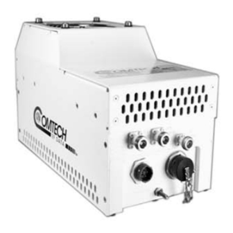
Page 235: Appendix C. Maintenance
C.1 Overview Figure C-1. Comtech EF Data LPOD Outdoor Amplifiers / BUCs The fans used by Comtech EF Data’s LPOD family of Outdoor Amplifiers / Block Up Converters (BUCs) (Figure C-1) are designed for long life, even in harsh environments. Still, they are mechanical devices, subject to wear, and may need replacement after several years. -
Page 236: Clean The Lpod Ps 1 Heat Sinks
LPOD C-, X-, or Ku-Band Outdoor Amplifier / Block Up Converter MN-LPOD Appendix C Revision 14 Sect. 4.5.4.6 Status | Trending Graphs (Chapter 4. ETHERNET INTERFACE OPERATION) Figure C-2. LPOD HTTP Interface ‘Status |Trending Graphs’ Page – Temperature Graph Example C.2 Clean the LPOD PS 1 Heat Sinks To clean the LPOD PS 1 Heatsinks, do these steps: Step... -
Page 237: Figure C-3. Lpod Ps 1 Shroud Screw Locations
LPOD C-, X-, or Ku-Band Outdoor Amplifier / Block Up Converter MN-LPOD Appendix C Revision 14 Step Task Reconnect the fan power supply by pressing the male and female connectors together until the locking mechanism snaps and locks – see Figure C-7. -
Page 238: Figure C-4. Remove The Fan Shroud
LPOD C-, X-, or Ku-Band Outdoor Amplifier / Block Up Converter MN-LPOD Appendix C Revision 14 Figure C-4. Remove the Fan Shroud Figure C-5. Disconnect the Fan Power Supply C–4... -
Page 239: Figure C-6. Lpod Ps 1 Heat Sink Locations
LPOD C-, X-, or Ku-Band Outdoor Amplifier / Block Up Converter MN-LPOD Appendix C Revision 14 Figure C-6. LPOD PS 1 Heat Sink Locations Figure C-7. Reconnect the Fan Power Supply C–5... -
Page 240: Clean The Lpod Ps 1.5 Heat Sinks
Appendix C Revision 14 C.3 Clean the LPOD PS 1.5 Heat Sinks To clean the LPOD PS 1.5 Heatsinks, do these steps: Step Task Disconnect power from the LPOD. Remove the screws from all four sides of the LPOD as needed – see Figure C-8. -
Page 241: Figure C-8. Lpod Ps 1.5 Shroud Screw Locations
Step 2 – make sure that you re-install the four longer screws at their same locations. Torque the screws to 8 ±1 inch lbs. Reconnect the power source to the LPOD. Figure C-8. LPOD PS 1.5 Shroud Screw Locations C–7... -
Page 242: Figure C-9. Remove The Fan Shroud
LPOD C-, X-, or Ku-Band Outdoor Amplifier / Block Up Converter MN-LPOD Appendix C Revision 14 Figure C-9. Remove the Fan Shroud Figure C-10. Disconnect the Fan 1 / Fan 2 Power Supplies C–8... -
Page 243: Figure C-11. Lpod Ps 1.5 Heat Sink Location
LPOD C-, X-, or Ku-Band Outdoor Amplifier / Block Up Converter MN-LPOD Appendix C Revision 14 Figure C-11. LPOD PS 1.5 Heat Sink Location Figure C-12. Reconnect the Fan 1 / Fan 2 Power Supplies C–9... -
Page 244: Clean The Lpod Ps 2 Heat Sinks
LPOD C-, X-, or Ku-Band Outdoor Amplifier / Block Up Converter MN-LPOD Appendix C Revision 14 C.4 Clean the LPOD PS 2 Heat Sinks To clean the LPOD PS 2 Heatsinks, do these steps: Step Task Disconnect the power source from the LPOD. Remove the screws from the sides and end of the LPOD as needed –... -
Page 245: Figure C-13. Lpod Ps 2 Shroud Screw Locations
LPOD C-, X-, or Ku-Band Outdoor Amplifier / Block Up Converter MN-LPOD Appendix C Revision 14 Figure C-13. LPOD PS 2 Shroud Screw Locations Figure C-14. Remove the Fan Shroud C–11... -
Page 246: Figure C-15. Disconnect The Fan 1 / Fan 2 Power Supplies
LPOD C-, X-, or Ku-Band Outdoor Amplifier / Block Up Converter MN-LPOD Appendix C Revision 14 Figure C-15. Disconnect the Fan 1 / Fan 2 Power Supplies Figure C-16. LPOD PS 2 Heat Sink Locations C–12... -
Page 247: Figure C-17. Reconnect The Fan 1 / Fan 2 Power Supplies
LPOD C-, X-, or Ku-Band Outdoor Amplifier / Block Up Converter MN-LPOD Appendix C Revision 14 Figure C-17. Reconnect the Fan 1 / Fan 2 Power Supplies C–13... -
Page 248: Water Tight Sealing
LPOD C-, X-, or Ku-Band Outdoor Amplifier / Block Up Converter MN-LPOD Appendix C Revision 14 C.5 Water Tight Sealing CAUTION Before you resume operation of your equipment, you MUST make sure that all external cable assemblies for the outdoor equipment are properly sealed to prevent water intrusion. - Page 250 2114 85281 WEST TH STREET TEMPE ARIZONA 480 • 333 • 2200 PHONE 480 • 333 • 2161...
Need help?
Do you have a question about the LPOD PS 1.5 and is the answer not in the manual?
Questions and answers