Comtech EF Data LPOD Installation And Operation Manual
Outdoor amplifier / block up converter (buc)
Hide thumbs
Also See for LPOD:
- Hardware installation and operation manual (152 pages) ,
- Installation and operation manual (250 pages)
Table of Contents
Advertisement
Quick Links
LPOD
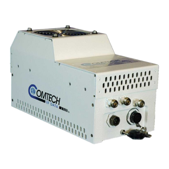
Outdoor Amplifier / Block Up Converter (BUC)
Installation and Operation Manual
IMPORTANT NOTE: The information contained in this document supersedes all previously published
information regarding this product. Product specifications are subject to change without prior notice.
Part Number MN-LPOD
Revision 9
Advertisement
Table of Contents

Related Manuals for Comtech EF Data LPOD


Summary of Contents for Comtech EF Data LPOD
-
Page 1: Installation And Operation Manual
Outdoor Amplifier / Block Up Converter (BUC) Installation and Operation Manual IMPORTANT NOTE: The information contained in this document supersedes all previously published information regarding this product. Product specifications are subject to change without prior notice. Part Number MN-LPOD Revision 9... - Page 3 Errata A for MN-LPOD Rev 9 Comtech EF Data Documentation Update Subject: Update Section1.5.1, power specifications, to match data sheet Errata Part Number: ER-LPOD-EA9 (Errata documents are not revised) PLM CO Number: C-0029955 Comments: See attached page(s). The new information will be included in the next released revision of the manual.
- Page 4 ER-LPOD-EA9 Rev - PLM C-0029955...
- Page 5 ER-LPOD-EA9 Rev - PLM C-0029955...
- Page 6 BLANK PAGE ER-LPOD-EA9 Rev - PLM C-0029955...
- Page 7 Errata B for MN-LPOD Rev 9 Comtech EF Data Documentation Update Subject: Update Table A-4, add part list find numbers to match exploded drawing Errata Part Number: ER-LPOD-EB9 (Errata documents are not revised) PLM CO Number: C-0030709 Comments: See attached page(s). The new information will be included in the next released revision of the manual.
- Page 8 ER-LPOD-EB9 Rev - PLM C-0030709...
- Page 9 Outdoor Amplifier / Block Up Converter (BUC) Installation and Operation Manual Part Number MN-LPOD Revision 9 Copyright © 2013 Comtech EF Data. All rights reserved. Printed in the USA. Comtech EF Data, 2114 West 7th Street, Tempe, Arizona 85281 USA, 480.333.2200, FAX: 480.333.2161...
- Page 10 This page is intentionally blank.
-
Page 11: Table Of Contents
1 2 B 1 2 B L imitations of Warranty .......................... xiv 1 3 B 1 3 B E xclusive Remedies ..........................xv Getting Help ........................... xvi Contacting Comtech EF Data ........................xvi Returning a Product for Upgrade or Repair ................... xvii CHAPTER 1. -
Page 12: Table Of Contents
2.2.2 Connector ‘J2 | RF OUT’ ......................2–3 2.2.3 Connector ‘J3 | POWER IN’ (AC Power Mains) ................. 2–4 2.2.3.1 LPOD PS 1, PS 1.5 ‘J3 | POWER IN’ (AC Power Main) ............2–4 2.2.3.2 LPOD PS 2 ‘J3 | POWER IN’ (AC Power Main) ..............2–4 2.2.4 Connector ‘J3 | POWER IN’... - Page 13 LPOD Outdoor Amplifier / Block Up Converter (BUC) Revision 9 Table of Contents MN-LPOD CHAPTER 3. UPDATING FIRMWARE ................3–1 Introduction ........................3–1 Getting Started: Preparing for the Firmware Download ............3–2 Downloading and Extracting the Firmware Update .............. 3–7 Performing the FTP Upload Procedure .................
- Page 14 LPOD Outdoor Amplifier / Block Up Converter (BUC) Revision 9 Table of Contents MN-LPOD 4.5.4.4.1 Status | Summary ..................... 4–24 4.5.4.4.2 Status | Status ......................4–25 4.5.4.4.3 Status | FETs ......................4–26 4.5.4.4.4 Status | Events ......................4–27 4.5.4.4.5 Status | Statistics ...................... 4–29 4.5.4.4.6 Status | Graphs ......................
-
Page 15: Tables
TABLES Table 2-1. ‘J2 | RF OUT’ Interface Type ....................2–3 Table 2-2. LPOD PS 1/PS 1.5 ‘J3 | POWER IN’ Pin Assignments ..............2–4 Table 2-3. LPOD PS 2 ‘J3 | POWER IN’ Pin Assignments ................2–4 Table 2-4. LPOD PS 1 ‘J3 | POWER IN’ Pin Assignments ................2–5 Table 2-5. -
Page 16: Figures
Table A-5. Parts List for KT-0000104 LPOD PS 1 1:1 Redundancy Kit ............. A–26 Table A-6. Parts List for KT-0000090 LPOD PS 1 C-Band Coax Output 1:1 Redundancy Kit ....A–30 Table A-7. Parts List for KT-0000089 LPOD PS 1 Ku-Band 1:1 Redundancy Kit ........A–34 Table A-8. - Page 17 Figure A-18. KT-0000170 LPOD PS 1 X-Band 1:1 Redundancy Kit (Exploded View) ....... A–39 Figure A-19. KT-0020526 LPOD PS 1.5 C-Band DC Option 1:1 Redundancy Kit (Assembled View) ..A–41 Figure A-20. KT-0020526 LPOD PS 1.5 C-Band DC Option 1:1 Redundancy Kit (Exploded View, Steps 1 & 2) ................................ A–43 Figure A-21.
- Page 18 MN-LPOD Figure C-10. Disconnect the Fan 1 / Fan 2 Power Supplies ..............C–7 Figure C-11. LPOD PS 1.5 Heat Sink Location .................... C–8 Figure C-12. Reconnect the Fan 1 / Fan 2 Power Supplies ............... C–8 Figure C-13. LPOD PS 2 Shroud Screw Locations ..................C–10 Figure C-14.
-
Page 19: Preface
LPOD PS 1, PS 1.5, or PS 2. Related Documents Comtech EF Data CLC-10 Handheld Terminal M&C Accessory for LPOD or SPOD PS 1, PS 1.5, PS 2 • User’s Guide (CEFD P/N MN-CLC10) •... -
Page 20: B C Onventions And References
The new designation of the Electronic Industries Association (EIA) supersedes the Recommended Standard (RS) designations. References to the old designations may be shown when depicting actual text (e.g., RS-232) displayed on the LPOD Web Server pages or serial remote interface. All other references in the manual refer to EIA designations. -
Page 21: Metric Conversion
LPOD. • Lightning: Lightning strikes on or around the antenna will generate extremely high voltages on all cables connected to the LPOD. Depending on the severity of the strike, the LPOD’s xiii... -
Page 22: B W Arranty Policy
MN-LPOD internal surge protection combined with the recommended external suppression may protect the LPOD’s power supply. However, if the installation will be in an area with a high probability of lightning strikes, Comtech EF Data recommends the installation of surge suppression on the RF and IF cables. - Page 23 MN-LPOD The warranty does not cover replacement or repair necessitated by loss or damage from any cause beyond the control of Comtech EF Data Corporation, such as lightning or other natural and weather related events or wartime environments. The warranty does not cover any labor involved in the removal and or reinstallation of warranted equipment or parts on site, or any labor required to diagnose the necessity for repair or replacement.
-
Page 24: Getting Help
Be prepared to provide the product model number and its serial number. Contact Comtech EF Data Customer & Technical Support during normal business hours (Monday through Friday, 8 A.M. to 5 P.M Mountain Standard Time (MST)): For:... -
Page 25: Returning A Product For Upgrade Or Repair
Return Material Authorization section in its entirety. Request a Return Material Authorization Number: • On the Comtech EF Data Home page: From the SUPPORT column at the bottom of the page, select the RMA Request hyperlink;... - Page 26 LPOD Outdoor Amplifier / Block Up Converter (BUC) Revision 9 Preface MN-LPOD Notes: xviii...
-
Page 27: Chapter 1. Introduction
Chapter 1. INTRODUCTION Overview Comtech EF Data’s LPOD family of Outdoor Amplifiers / Block Up Converters (BUCs) – referred to collectively throughout this manual as the LPOD – deliver their rated power, guaranteed, to the transmit waveguide flange at the 1 dB compression point. The LPOD provides a cost effective, more reliable replacement for Traveling Wave Tube (TWT) amplifiers in satellite communications. -
Page 28: Functional Description
LNB bias T facilitates multi-carrier and redundant operations required of small-to medium-sized hub installations. As shown in Figure 1-1, Comtech EF Data’s LPOD is available in three models: the PS 1, PS 1.5 and PS 2. Each LPOD consists of a CEFD SSPA module with the Monitor/Control Processor (MCP), a power supply, and a fan assembly. -
Page 29: Smart Buc" Functionality
1.3.7 Optional LNB Support The LPOD was designed with the evolution of L-band systems in mind. L-band IF topologies are no longer relegated to low power single carrier installations, and are now found in larger multi- carrier installations. A challenge presented by multi-carrier L-band systems is the presence of DC and reference components on the Tx/Rx L-band interfaces. -
Page 30: Theory Of Operation
LPOD Outdoor Amplifier / Block Up Converter (BUC) Revision 9 Introduction MN-LPOD Theory of Operation 1.4.1 SSPA Block Diagrams See Figure 1-2 and Figure 1-3 for the LPOD block diagrams. The major components of an LPOD unit are: • SSPA Module • Cooling System •... -
Page 31: Sspa Module
LPOD Outdoor Amplifier / Block Up Converter (BUC) Revision 9 Introduction MN-LPOD Figure 1-3. LPOD PS 2 Block Diagram 1.4.2 SSPA Module The amplifier module performs the core function of the unit. An isolator is at the RF input to ensure good voltage standing wave ratio (VSWR). -
Page 32: Cooling System
1.4.3 Cooling System The LPOD contains a robust heat sink and thermal design to maintain a low operating temperature. The PS 1 contains one temperature-controlled fan, and the PS 1.5 and PS 2 contain two temperature-controlled fans that are monitored by the M&C board. The fans draw cool outside air in across the power supply and specialized heat sink. -
Page 33: Block Up Converter (Buc) Input
Unlike most BUCs, no DC bias voltage should be provided on the center conductor of the L-Band coax. In addition, the LPOD is available with an internal 10 MHz reference. As, such, no 10 MHz reference is required on the center conductor of the L-Band coax. If a reference is provided on the coax, the internal reference will detect and lock to it. -
Page 34: Summary Of Specifications
LPOD Outdoor Amplifier / Block Up Converter (BUC) Revision 9 Introduction MN-LPOD Summary of Specifications 1.5.1 Characteristics Note 1 IF Input Frequency RF Output Frequency 950 – 1525 MHz 5.850 – 6.425 GHz 950 – 1750 MHz 5.850 – 6.650 GHz (optional) 950 –... -
Page 35: Optional Internal Reference
LPOD Outdoor Amplifier / Block Up Converter (BUC) Revision 9 Introduction MN-LPOD Harmonics -50 dBc @ Prated – 3 dB Carrier Related -60 dBc min. @ P1dB In Band Spurious Level Non-Carrier -60 dBm max. ( Input Terminated) Related In Band LO Leakage -25 dBm max. -
Page 36: Environmental
LPOD Outdoor Amplifier / Block Up Converter (BUC) Revision 9 Introduction MN-LPOD 1.5.4 Environmental Standard -40º to 122ºF (-40º to 55ºC) Operating Temperature Optional -40º to 140ºF (-40º to 60ºC) Storage -67º to 167ºF (-55º to 75ºC) Humidity 100% condensing rain 2” per hour... -
Page 37: Dimensional Envelopes
LPOD Outdoor Amplifier / Block Up Converter (BUC) Revision 9 Introduction MN-LPOD Dimensional Envelopes Note the following: 1. Typical for all figures in each subsection, all dimensions are in inches. Bracketed dimensions, where shown, are in metric units (mm). 2. Unless otherwise noted, all figures depict AC Option, Waveguide Output units. -
Page 38: Lpod Ps 1 Dimensional Envelopes
LPOD Outdoor Amplifier / Block Up Converter (BUC) Revision 9 Introduction MN-LPOD 1.6.1 LPOD PS 1 Dimensional Envelopes Figure 1-4. LPOD PS 1 C-Band Dimensional Envelope (Coax Output) 1–12... -
Page 39: Figure 1-5. Lpod Ps 1 C-Band Dimensional Envelope (Waveguide Output)
LPOD Outdoor Amplifier / Block Up Converter (BUC) Revision 9 Introduction MN-LPOD Figure 1-5. LPOD PS 1 C-Band Dimensional Envelope (Waveguide Output) 1–13... -
Page 40: Figure 1-6. Lpod Ps 1 X-Band Dimensional Envelope
LPOD Outdoor Amplifier / Block Up Converter (BUC) Revision 9 Introduction MN-LPOD Figure 1-6. LPOD PS 1 X-Band Dimensional Envelope 1–14... -
Page 41: Figure 1-7. Lpod Ps 1 Ku-Band Dimensional Envelope
LPOD Outdoor Amplifier / Block Up Converter (BUC) Revision 9 Introduction MN-LPOD Figure 1-7. LPOD PS 1 Ku-Band Dimensional Envelope 1–15... -
Page 42: Lpod Ps 1.5 Dimensional Envelopes
LPOD Outdoor Amplifier / Block Up Converter (BUC) Revision 9 Introduction MN-LPOD 1.6.2 LPOD PS 1.5 Dimensional Envelopes Figure 1-8. LPOD PS 1.5 C-Band Dimensional Envelope (DC Option) 1–16... -
Page 43: Figure 1-9. Lpod Ps 1.5 X-Band Dimensional Envelope
LPOD Outdoor Amplifier / Block Up Converter (BUC) Revision 9 Introduction MN-LPOD Figure 1-9. LPOD PS 1.5 X-Band Dimensional Envelope 1–17... -
Page 44: Figure 1-10. Lpod Ps 1.5 Ku-Band Dimensional Envelope
LPOD Outdoor Amplifier / Block Up Converter (BUC) Revision 9 Introduction MN-LPOD Figure 1-10. LPOD PS 1.5 Ku-Band Dimensional Envelope 1–18... -
Page 45: Lpod Ps 2 Dimensional Envelopes
LPOD Outdoor Amplifier / Block Up Converter (BUC) Revision 9 Introduction MN-LPOD 1.6.3 LPOD PS 2 Dimensional Envelopes Figure 1-11. LPOD PS 2 C-Band Dimensional Envelope 1–19... -
Page 46: Figure 1-12. Lpod Ps 2 X-Band Dimensional Envelope
LPOD Outdoor Amplifier / Block Up Converter (BUC) Revision 9 Introduction MN-LPOD Figure 1-12. LPOD PS 2 X-Band Dimensional Envelope 1–20... -
Page 47: Figure 1-13. Lpod Ps 2 Ku-Band Dimensional Envelope
LPOD Outdoor Amplifier / Block Up Converter (BUC) Revision 9 Introduction MN-LPOD Figure 1-13. LPOD PS 2 Ku-Band Dimensional Envelope 1–21... - Page 48 LPOD Outdoor Amplifier / Block Up Converter (BUC) Revision 9 Introduction MN-LPOD Notes: 1–22...
-
Page 49: Overview
Overview This chapter summarizes the connectors provided for all necessary external connections between the LPOD PS 1 (Figure 2-1), PS 1.5 (Figure 2-2), or PS 2 (Figure 2-3) models and other equipment. Basic installation and operational startup information is provided in Sect. 2.3. For a detailed overview on the LPOD’s operability, see Chapter 4. -
Page 50: Figure 2-1. Lpod Ps 1 Connectors
LPOD Outdoor Amplifier / Block Up Converter Revision 9 System Connections, Installation and Startup MN-LPOD Figure 2-1. LPOD PS 1 Connectors Figure 2-2. LPOD PS 1.5 Connectors Figure 2-3. LPOD PS 2 Connectors 2–2... -
Page 51: Chapter 2. System Connections, Installation And Startup
The ‘J2 | RF OUT’ connector may be a waveguide or coaxial interface – the type of interface used depends on the LPOD model and/or frequency range of the unit, as described in Table 2-1 and as shown in Figures 2-1, 2-2, and 2-3. -
Page 52: Connector 'J3 | Power In' (Ac Power Mains)
2.2.3 Connector ‘J3 | POWER IN’ (AC Power Mains) FOR SAFETY REASONS, TAKE CARE TO NOTE THAT THE ‘J3’ AC POWER CONNECTION PIN ASSIGNMENTS FOR EACH LPOD MODEL ARE NOT THE SAME. FAILURE TO CAREFULLY REVIEW THE INFORMATION PROVIDED IN THE SECTIONS THAT FOLLOW MAY RESULT IN PRODUCT DAMAGE OR PERSONAL INJURY. -
Page 53: Connector 'J3 | Power In' (Dc Power Mains)
MAY RESULT IN PRODUCT DAMAGE OR PERSONAL INJURY. For all LPOD models, the prime power input requirement is 38-72 VDC. The total power required from the prime power supply depends on the model used. Please refer to Sect. 1.5 Summary of Specifications. -
Page 54: Lpod Ps 2 'J3 | Power In' (Dc Power Main)
LPOD PS 2 ‘J3 | POWER IN’ 48VDC Power Main Option The connector type and mating connector specification and the pin assignments (Table 2-7) unique to the LPOD PS 2 48 VDC power interface option are as follows: Unit Connector Type: CEFD P/N CN-0000288 (ITT Cannon CA3102E20-15SB-F80A232). -
Page 55: Connector 'J6 | Com1' (Remote Communications And Discrete Control Port)
2.2.5 Connector ‘J 6 | COM1’ (R emote Communications and Dis crete Control Port) The ‘J6 | COM 1’ discrete control connector is primary input controlling monitoring the LPOD. It is a 19-pin circular connector, type MS3112E14-19S. The pinout specification is contained in Table 2-8. Mating connector: ITT: KPT06J14-19P or MS3116J14-19P. -
Page 56: Connector 'J9 | Output Sample' (Ps 2 Only)
LPOD Outdoor Amplifier / Block Up Converter Revision 9 System Connections, Installation and Startup MN-LPOD 2.2.6 Connector ‘J9 | OUTPUT SAMPLE’ (PS 2 Only) The ‘J9 | OUTPUT SAMPLE’ port is a Type ‘N’ female connector available only on the PS 2 model. It provides a nominal -40 dB sample of the output signal. -
Page 57: Standalone Installation Of The Lpod
OUT’ port. Individuals can be exposed to dangerously high electromagnetic levels. The LPOD does not contain a ‘Power On/Off’ switch. It is powered ON by connecting the ‘J3 | POWER IN’ connector to the appropriate prime power source. The Mute or Transmit status of the SSPA will automatically come up in the last stored state (factory default = Transmit on, not muted). -
Page 58: Figure 2-5. Pl/12319-1 Universal Pole Mounting Kit
LPOD Outdoor Amplifier / Block Up Converter Revision 9 System Connections, Installation and Startup MN-LPOD PL/12319-1 Universal Pole Mounting Kit ITEM CEFD PART NO. DESCRIPTION BRACKET, UNISTRUT (SHOWN FOR CLARITY ONLY, INCLUDED IN CEFD P/N FP/BR0078 BRACKET MODIFICATION POLE MOUNTING... -
Page 59: Figure 2-6. Kt-0000095 Lpod Ps 1/Ps 1.5 Single Unit Mounting Kit
BRACKET MODIFICATION POLE MOUNTING KIT HW/1/4-20X1/2FH SCREW, 1/4-20 X 1/2 FH PHIL, 82, UCUT, SS HW-0000070 SCREW, HEX, SERR FLANGE HD, 3/8-16 x 3/4, SS HW/3/8SPRINGNUT SPRINGNUT, 3/8-16, SHORT SPRING, SS (P3300) Figure 2-6. KT-0000095 LPOD PS 1/PS 1.5 Single Unit Mounting Kit 2–11... -
Page 60: Figure 2-7. Kt-0000125 Lpod Ps 2 Single Unit Mounting Kit
SCREW, HEX, SERR FLANGE HEAD, 3/8-16 x 3/4, S.S HW/3/8SPRINGNUT SPRING NUT, 3/8-16, SHORT SPRING, SS (P3300) HW/5/16-18X3/4B BOLT, HEX HEAD, 5/16-18 X 3/4, SS HW/5/16-SPLIT LOCK WASHER, SPLIT, 5/16 HW/5/16-FLT WASHER, FLAT, 5/16 Figure 2-7. KT-0000125 LPOD PS 2 Single Unit Mounting Kit 2–12... -
Page 61: Figure 2-8. Kt-0020524 Lpod Ps 2 Single Unit Shelf Style Mounting Kit
BOLT, HEX HEAD, 5/16-18 X 3/4 LG HW/3/8-FLT FLAT WASHER, 3/8 HW/3/8-SPLIT LOCK WASHER, SPLIT 3/8 HW/3/8-16X1B BOLT, HEX HEAD, 3/8-16 X 1 LG HW/3/8-16X1.25B BOLT, HEX HEAD, 3/8-18 X 1.25 LG Figure 2-8. KT-0020524 LPOD PS 2 Single Unit Shelf Style Mounting Kit 2–13... - Page 62 LPOD Outdoor Amplifier / Block Up Converter Revision 9 System Connections, Installation and Startup MN-LPOD Notes: 2–14...
-
Page 63: Chapter 3. Updating Firmware
Firmware updates may be applied to an LPOD system without having to remove it from operation. If you need to update the firmware, you can acquire the download from the Comtech EF Data Web site (www.comtechefdata.com) or from Comtech EF Data Customer Support during normal business hours via e-mail or on CD by standard mail delivery. -
Page 64: Getting Started: Preparing For The Firmware Download
LPODnet (part of M&C Netbook Accessory Kit CEFD Kit KT-0000203). o Your serial connection may use either an user-fabricated adapter cable to connect the PC serial port to the LPOD, or the optional CLC-10 Handheld Terminal (part of M&C Accessory Kit (CEFD Kit KT-0020518). The following... - Page 65 • Display New line Rx/Tx: CR NONE • Local Echo = ON C. On the LPOD – Power up the unit. Your power connection varies depending on your ordered unit. See Sect. 2.2.3 Connector ‘J3 | POWER IN’ (AC Power Mains) or Sect. 2.2.4 Connector ‘J3 | POWER IN’...
- Page 66 • If using serial remote control, you may use the terminal emulator program or the CLC-10 to execute remote commands and queries with the LPOD. The firmware revision levels can be obtained with the following remote queries: o Abbreviated: <0/SWR? (returns basic Boot, Bulk1 and Bulk2 information) o Detailed: <0/FRW? (returns complete Boot, Bulk1 and Bulk2 information)
- Page 67 LPOD Outdoor Amplifier / Block Up Converter (BUC) Revision 9 Updating Firmware MN-LPOD B. Use Windows Explorer to create and rename the temporary folder. • Select File > New > Folder to create the new, temporary folder in the active location.
- Page 68 LPOD Outdoor Amplifier / Block Up Converter (BUC) Revision 9 Updating Firmware MN-LPOD D. Use Windows Command-line to create the temporary folder. • First, click [Start] on the Windows taskbar, and then click the ‘Run...’ icon (or, depending on Windows OS versions prior to Windows 95, click the ‘MS-DOS Prompt’...
-
Page 69: Downloading And Extracting The Firmware Update
MN-LPOD Downloading and Extracting the Firmware Update 1. First, download the firmware update file from the Comtech EF Data Web site: A. Go online to www.comtechefdata.com. B. On the Main page – Under Support Information or the Support tab, select the Software Downloads hyperlink. - Page 70 LPOD Outdoor Amplifier / Block Up Converter (BUC) Revision 9 Updating Firmware MN-LPOD o Click [Open] to turn over file extraction to the user-supplied utility program. Be sure to extract the firmware files to the ‘temp’ folder created earlier. o Click [Save] to open the ‘Save As’ window. Be sure to select and [Save] the archive *.exe or *.zip file to the ‘temp’...
-
Page 71: Performing The Ftp Upload Procedure
1. Use Command-Line to send a ‘PING’ command to confirm proper connection and communication between the user PC and the LPOD: • Obtain the IP Address of the unit using serial remote control or the LPOD Web Server Interface: o Using Serial Remote Control – Type the “<0/IPA?” remote query (without quotes) at the command prompt. - Page 72 MN-LPOD The response should confirm whether the unit is properly connected and communicating. 2. Use Command-line to transfer (FTP) the files from the user PC to the LPOD: • Type "ftp xxx.xxx.xxx.xxx" (where ‘xxx.xxx.xxx.xxx’ denotes the unit IP Address). •...
-
Page 73: Chapter 4. Ethernet-Based Remote Product Management
• The LPOD is operating with the latest version firmware files. • The LPOD is connected to a user-supplied Windows-based PC as follows: o The PC’s Ethernet port is connected to the LPOD ‘J6 | COM1’ port using the available CA-0000352 Ethernet Interface Cable (part of CEFD Kit KT-0000203) in combination with a user-supplied hub or switch. -
Page 74: Ethernet Management Interface Protocols
The following MIB files are associated with the LPOD: MIB File/Name (where Description ‘x’ is revision letter) FW-0000291x.mib ComtechEFData MIB file gives the root tree for ALL Comtech EF Data LPOD products (PSx) and consists of only the following OID: ComtechEFData Root MIB file Name: comtechEFData Type: MODULE-IDENTITY OID: 1.3.6.1.4.1.6247... -
Page 75: 4.3.2 Snmp Community Strings
Notes for information on the required FW/SW compatibility. 4.3.3 SNMP Traps The LPOD has the ability to send out SNMP traps both when a fault occurs and when a fault clears in the unit. The SNMP agent supports both “SNMPv1” and “v2c”. The “Traps” file only needs to be compiled if “SNMPv1”... - Page 76 LPOD Outdoor Amplifier / Block Up Converter Revision 9 Ethernet-based Remote Product Management MN-LPOD The LPOD supports the following Faults v1 traps and v2 notifications: Faults SNMPv1 traps: lpodPowerSupply24V1StatusV1 62474801 lpodPowerSupply24V2StatusV1 62474802 lpodPowerSupplyLNBStatusV1 62474803 lpodPowerSupply13VStatusV1 62474804 lpodPowerSupply10VStatusV1 62474805 lpodRFPowerSupply10V1StatusV1 62474806...
- Page 77 LPOD Outdoor Amplifier / Block Up Converter Revision 9 Ethernet-based Remote Product Management MN-LPOD lpodRFPowerSupply10V2Status 1.3.6.1.4.1.6247.48.1.3.1.7 lpodPowerSupply7V8TStatus 1.3.6.1.4.1.6247.48.1.3.1.8 lpodPowerSupply5V8TStatus 1.3.6.1.4.1.6247.48.1.3.1.9 lpodPowerSupply2V5TStatus 1.3.6.1.4.1.6247.48.1.3.1.10 lpodPowerSupply1V2TStatus 1.3.6.1.4.1.6247.48.1.3.1.11 lpodPowerSupplyNeg5V8TStatus 1.3.6.1.4.1.6247.48.1.3.1.12 lpodFan1Status 1.3.6.1.4.1.6247.48.1.3.1.13 lpodFan2Status 1.3.6.1.4.1.6247.48.1.3.1.14 lpodTemperatureStatus 1.3.6.1.4.1.6247.48.1.3.1.15 lpodShutdownStatus 1.3.6.1.4.1.6247.48.1.3.1.16 lpodI2CStatus 1.3.6.1.4.1.6247.48.1.3.1.17 lpodForwardPowerStatus 1.3.6.1.4.1.6247.48.1.3.1.18 lpodChecksumStatus 1.3.6.1.4.1.6247.48.1.3.1.19 lpodFPGADoneStatus 1.3.6.1.4.1.6247.48.1.3.1.20...
-
Page 78: Telnet Interface
MN-LPOD Telnet Interface The LPOD provides a Telnet interface for the purpose of equipment M&C via the standard Remote Control protocol. The Telnet interface requires user login at the Administrator level and Read/Write level. An example of the login process is shown here: Once logged into the Telnet interface as the Administrator, you can access the standard remote control interface defined in Chapter 5. - Page 79 LPOD Outdoor Amplifier / Block Up Converter Revision 9 Ethernet-based Remote Product Management MN-LPOD Configure HyperTerminal as follows: 1. Be sure to properly define the “Connect To” Telnet connection properties (File Properties), as shown below at the near right: Enter the LPOD’s...
-
Page 80: Web Server (Http) Interface
MN-LPOD Web Server (HTTP) Interface A user-supplied web browser allows the full monitor and control (M&C) of the LPOD through its Web Server Interface. This non-secure embedded web application is designed for, and works best with, Microsoft’s Internet Explorer Version 5.5 or higher. -
Page 81: 4.5.2 User Login
See Chapter 5. SERIAL-BASED REMOTE PRODUCT MANAGEMENT for more information on the LRS and IPA commands. 4.5.2 User Login 1. From the PC, type http://192.168.1.4 (the default IP address for the LPOD) into the Address area of the browser: 2. The Login window will appear, similar to the example shown here. -
Page 82: 4.5.3 Web Server Interface - Operational Features
4.5.3 Web Server Interface – Operational Features 4.5.3.1 Menu Tree This menu tree diagram lists the features available through the LPOD Web Server Interface. This interface features four navigation tabs (shown in blue). The nested page hyperlinks (grey) provide access to individual Web pages. -
Page 83: Action Buttons
Revision 9 Ethernet-based Remote Product Management MN-LPOD 4.5.3.4 Action Buttons Action buttons are important in the LPOD Web Server Interface. Click an action button to do one of these tasks: • Refresh the page with current data. • Reset changed parameters to remove unsaved changes. -
Page 84: Web Server Interface - Web
4.5.4.1.1 Home | Home Use this page to identify the LPOD Web Server Interface, the specific product, and its assigned serial number. Click the Home tab and/or the nested Home hyperlink to return to this page from anywhere in the Web Server Interface. -
Page 85: Home | Contact
LPOD Outdoor Amplifier / Block Up Converter Revision 9 Ethernet-based Remote Product Management MN-LPOD 4.5.4.1.2 Home | Contact Use this page to see the contact information (phone, fax, or Web/e-mail hyperlinks) for Comtech EF Data Sales or Customer Support. Figure 4-2. Home | Contact Page... -
Page 86: Home | Support
LPOD Outdoor Amplifier / Block Up Converter Revision 9 Ethernet-based Remote Product Management MN-LPOD 4.5.4.1.3 Home | Support For this page to operate correctly, the Administrator must define the SMTP server, domain name, and destination on the Admin | Access page (see Sect.4.5.4.2.1 This page uses SMTP (Simple Mail Transport Protocol) to compose and send an e-mail message to Comtech EF Customer Support (techsupport@comtechefdata.com). -
Page 87: Admin
LPOD Outdoor Amplifier / Block Up Converter Revision 9 Ethernet-based Remote Product Management MN-LPOD 4.5.4.2 Admin Pages The Admin pages are available only to users who have logged in using the Administrator Name and Password. Click the Admin tab, and then select the Access or SNMP hyperlink to continue. - Page 88 System Account Access Information. Webpage Timeout The Webpage Timeout determines a desired time lapse before the LPOD Web Server Interface pages time out. Use the drop-down list to select five minutes or eight hours. The default timeout setting is five minutes. Click [Submit] when done.
-
Page 89: Admin | Snmp
4.5.4.2.2 Admin | SNMP Sect. 4.3 SNMP INTERFACE The Administrator must use this page to manage the LPOD SNMP (Simple Network Management Protocol) settings. Figure 4-5. Admin | SNMP Page Click [Refresh] (at the top of the page) to update the page appearance to the current operating configuration. -
Page 90: Config
LPOD Outdoor Amplifier / Block Up Converter Revision 9 Ethernet-based Remote Product Management MN-LPOD Click [Submit SNMP] to save any changes. Otherwise, click [Reset] to revert to the previously assigned SNMP designations. 4.5.4.3 Config Pages Click the Config tab, and then click the Amplifier, LNB, Utility, or Redundancy hyperlink to continue. - Page 91 LPOD Outdoor Amplifier / Block Up Converter Revision 9 Ethernet-based Remote Product Management MN-LPOD • Amplifier – Use the drop-down list to select the amplifier as either On or Off. • Attenuation (dB) – Enter a valid attenuation level (00.00 to 20.00 dB) in 0.25 dB steps.
-
Page 92: Config | Lnb
LPOD Outdoor Amplifier / Block Up Converter Revision 9 Ethernet-based Remote Product Management MN-LPOD 4.5.4.3.2 Config | LNB Use this page to configure Low-Noise Block Downconverter parameters, and display the LNB status for L-Band operation. Figure 4-7. Config | LNB Page Click [Refresh] (at the top of the page) to update the page appearance to the current operating configuration. -
Page 93: Config | Utility
Click [Calibrate] to perform an LNB calibration and display the updated read-only value. 4.5.4.3.3 Config | Utility Use this page to configure LPOD operating parameters. Figure 4-8. Config | Utility Page Click [Refresh] (at the top of the page) to update the page appearance to the current operating configuration. - Page 94 Use the drop-down list to select the Next Reboot Image as Image 1 or 2. Press [Submit] when done. Perform Soft Reboot Click [Reboot Now] to reboot the LPOD using the Current Active Firmware Image. Firmware Information (read-only) This read-only scrollable window provides information about the currently loaded Bootrom. For the complete Bulk1 and Bulk2 information, scroll through all the constituent firmware blocks that make up the bulk.
-
Page 95: Config | Redundancy
Config | Redundancy Appendix A. 1:1 REDUNDANCY Use this page to configure the LPOD’s Redundancy Switch Mode. Figure 4-9. Config | Redundancy Page Click [Refresh] (at the top of the page) to update the page appearance to the current operating configuration. -
Page 96: Status Pages
Graphs hyperlink to continue. 4.5.4.4.1 Status | Summary Use this read-only page to view pertinent condensed information about the LPOD unit and its current operating state. Figure 4-10. Status | Summary Page Click [Refresh] (at the top of the page) to update the page appearance to the current polled configuration and operating conditions. -
Page 97: Status | Status
A redundant switchover occurs. 4.5.4.4.2 Status | Status Use this read-only page to review all pertinent information about the LPOD. Unlike the remaining pages available through this interface that refresh/update only when manually selected, the ‘Status | Status’ page updates automatically once every 10 seconds. -
Page 98: Status | Fets
MN-LPOD 4.5.4.4.3 Status | FETs Use this read-only page to monitor the current operating status of the LPOD’s Q01 through Q09 RF Power Field Effect Transistors (FETs) that are installed in the RF amplifier. Figure 4-12. Status | FETs page Click [Refresh] (at the top of the page) to update the page appearance to the current polled configuration and operating conditions. -
Page 99: Status | Events
Status | Events Use this page to view with all pertinent information about stored events, and to define the alarm parameters that determine how ongoing LPOD operations shall trigger events and alarms. Figure 4-13. Status | Events Page Click [Refresh] (at the top of the page) to update the page appearance to the current polled configuration and operation conditions. - Page 100 LPOD Outdoor Amplifier / Block Up Converter Revision 9 Ethernet-based Remote Product Management MN-LPOD Alarm Mask Use the drop-down lists to select each alarm as Fault, Alarm, or Masked for: • Low Forward RF Power • Fan Speed • LNB 22V Power Supply •...
-
Page 101: Status | Statistics
MN-LPOD 4.5.4.4.5 Status | Statistics Use this page to review all unread (stored) statistics, and to configure how the LPOD handles and displays statistics. Figure 4-14. Status | Statistics page Click [Refresh] (at the top of the page) to update the page appearance to the current polled operating conditions. - Page 102 LPOD Outdoor Amplifier / Block Up Converter Revision 9 Ethernet-based Remote Product Management MN-LPOD Statistics Configuration • Statistics Logging – Use the drop-down list to select either Enable or Disable to set the Statistics Logging function. • Statistics Interval – Enter the interval, in minutes, at which statistics are logged. Minimum resolution is 1 minute (001);...
-
Page 103: Status | Graphs
LPOD Outdoor Amplifier / Block Up Converter Revision 9 Ethernet-based Remote Product Management MN-LPOD 4.5.4.4.6 Status | Graphs This scrollable page features a universal page controls bar plus seven trending and operations graphs that provide statistics for the following parameters: •... - Page 104 LPOD Outdoor Amplifier / Block Up Converter Revision 9 Ethernet-based Remote Product Management MN-LPOD Click [Refresh] (at the top of the page) to update the graphs to their current polled states. Control Bar and Refresh Tab Use the Control Bar to choose the time, date, and duration of the trending information displayed on the graphs.
- Page 105 LPOD Outdoor Amplifier / Block Up Converter Revision 9 Ethernet-based Remote Product Management MN-LPOD Temperature Graph As noted by the graph legend, the blue line displays the unit's Amplifier (heat sink) temperature; the red line displays the Ambient (outdoor) temperature, if the required sensor has been installed in the unit.
- Page 106 LPOD Outdoor Amplifier / Block Up Converter Revision 9 Ethernet-based Remote Product Management MN-LPOD LNB Current Graph This graph displays the LNB current only if an LNB is connected to the system and is drawing current from the LNB current source.
- Page 107 -5°C and +15°C. At temperatures at or below -5°C, the LPOD minimizes its fan speed; at temperatures at or above +15°C, the LPOD maximizes its fan speed. The example provided here demonstrates the fan running at minimum, proportional, and maximum speeds.
- Page 108 LPOD Outdoor Amplifier / Block Up Converter Revision 9 Ethernet-based Remote Product Management MN-LPOD Notes: 4–36...
-
Page 109: Chapter 5. Serial-Based Remote Product Management
Serial-based remote product management of Comtech EF Data’s LPOD family of Outdoor Amplifiers / Block Up Converters (BUCs) is available using the LPOD’s ‘J6 | COM 1’ port. Some key parameters and procedures and their associated remote commands and queries are summarized, followed by detailed instructions for use of the serial remote control communication command and query interface. -
Page 110: Attenuator Control
The Mute command provides over 60 dB of RF on/off isolation. However, the Mute command only turns off the first few low power stages of the amplifier, the high power stages remain on. By allowing the higher power transistors to stay on, the LPOD remains in more thermally stable state should the mute condition be removed. - Page 111 LPOD Outdoor Amplifier / Block Up Converter (BUC) Revision 9 Serial-based Remote Product Management MN-LPOD • Thermal Shutdown – A temperature fault is indicated if the unit is +>90°C. This creates a summary fault and will cause the unit to mute itself and switch to the back-up unit (if in a redundant system). However, the 10V supply to the FET transistors will remain on until the unit reaches the thermal shutdown temperature of ≥...
-
Page 112: Power Detector
5.2.7 End-of-Life Commands Certain commands/queries are being marked by Comtech EF Data as End-of-Life (EOL). As noted in the format <description> in the Parameter Type field (in the Remote Commands and Queries tables in Sect. 5.4), while these commands are fully supported in this product it is highly recommended that the equivalent new commands be used for new implementations. -
Page 113: Remote Control Protocol And Structure
LPOD Outdoor Amplifier / Block Up Converter (BUC) Revision 9 Serial-based Remote Product Management MN-LPOD Remote Control Protocol and Structure The electrical interface is either an EIA-485 multi-drop bus (for the control of many devices) or an EIA-232 connection (for the control of a single device), and data is transmitted in asynchronous serial form, using ASCII characters. -
Page 114: Eia-232
LPOD Outdoor Amplifier / Block Up Converter (BUC) Revision 9 Serial-based Remote Product Management MN-LPOD 5.1.2 EIA-232 This is a much simpler configuration in which the Controller device is connected directly to the Target via a two-wire-plus-ground connection. Controller-to-Target data is carried, via EIA-232 electrical levels, on one conductor, and Target-to-Controller data is carried in the other direction on the other conductor. -
Page 115: 5.1.4.1 Start Of Packet
LPOD Outdoor Amplifier / Block Up Converter (BUC) Revision 9 Serial-based Remote Product Management MN-LPOD Target-to-Controller Optional Start of Packet Target Address Address Delimiter Instruction Code Code Qualifier End of Packet Arguments > A-Z, a-z =, ?, !, or *... -
Page 116: 5.1.4.4 Instruction Code
LPOD Outdoor Amplifier / Block Up Converter (BUC) Revision 9 Serial-based Remote Product Management MN-LPOD 5.1.4.4 Instruction Code This is a three-character alphabetic sequence that identifies the subject of the message. Wherever possible, the instruction codes have been chosen to have some significance. -
Page 117: 5.1.4.6 Optional Message Arguments
LPOD Outdoor Amplifier / Block Up Converter (BUC) Revision 9 Serial-based Remote Product Management MN-LPOD This character is used only if the Controller sends an instruction code which the Target does not recognize, the Target will acknowledge the message by echoing the invalid instruction, followed by the ! character. Example: XYZ! -
Page 118: Remote Commands And Queries
LPOD Outdoor Amplifier / Block Up Converter (BUC) Revision 9 Serial-based Remote Product Management MN-LPOD Remote Commands and Queries Column ‘C’ = Command; Column ‘Q’ = Query; columns marked ‘X’ designate instruction code as Command only, Query only, or Command/Query. - Page 119 If auto fault recovery is enabled, it will cause the output return to its pre-fault mute condition if all faults are cleared. If disabled, the output will remain muted even if all faults are cleared. The LPOD output will automatically be muted if one of the following fault conditions occurs: BUC lock detect fault •...
- Page 120 Pin K to Pin S on the discrete control connector then the RF mute will be disabled (MUT=0). Example (AUX Mute Enabled): AUX=1’cr’ Clear All Stored CAA= None Command only. CAA= Alarms Instructs the LPOD to clear all Stored Alarms. This command takes no arguments. CAA* Example: <1/CAA=’cr’ >0001/CAA=’cr’’lf’ Clear All Stored CAE= None Command only.
- Page 121 LPOD Outdoor Amplifier / Block Up Converter (BUC) Revision 9 Serial-based Remote Product Management MN-LPOD Command Arguments Response to Query Response to Query (Instruction for Command Description of Arguments Command (Instruction Parameter Type (Target to Code and or Response (Target to...
- Page 122 LPOD Outdoor Amplifier / Block Up Converter (BUC) Revision 9 Serial-based Remote Product Management MN-LPOD Command Arguments Response to Query Response to Query (Instruction for Command Description of Arguments Command (Instruction Parameter Type (Target to Code and or Response (Target to...
- Page 123 LPOD Outdoor Amplifier / Block Up Converter (BUC) Revision 9 Serial-based Remote Product Management MN-LPOD Command Arguments Response to Query Response to Query (Instruction for Command Description of Arguments Command (Instruction Parameter Type (Target to Code and or Response (Target to...
- Page 124 LPOD Outdoor Amplifier / Block Up Converter (BUC) Revision 9 Serial-based Remote Product Management MN-LPOD Command Arguments Response to Query Response to Query (Instruction for Command Description of Arguments Command (Instruction Parameter Type (Target to Code and or Response (Target to...
- Page 125 LPOD Outdoor Amplifier / Block Up Converter (BUC) Revision 9 Serial-based Remote Product Management MN-LPOD Command Arguments Response to Query Response to Query (Instruction for Command Description of Arguments Command (Instruction Parameter Type (Target to Code and or Response (Target to...
- Page 126 LPOD Outdoor Amplifier / Block Up Converter (BUC) Revision 9 Serial-based Remote Product Management MN-LPOD Command Arguments Response to Query Response to Query (Instruction for Command Description of Arguments Command (Instruction Parameter Type (Target to Code and or Response (Target to...
- Page 127 LPOD Outdoor Amplifier / Block Up Converter (BUC) Revision 9 Serial-based Remote Product Management MN-LPOD Command Arguments Response to Query Response to Query (Instruction for Command Description of Arguments Command (Instruction Parameter Type (Target to Code and or Response (Target to...
- Page 128 LPOD Outdoor Amplifier / Block Up Converter (BUC) Revision 9 Serial-based Remote Product Management MN-LPOD Command Arguments Response to Query Response to Query (Instruction for Command Description of Arguments Command (Instruction Parameter Type (Target to Code and or Response (Target to...
- Page 129 LPOD Outdoor Amplifier / Block Up Converter (BUC) Revision 9 Serial-based Remote Product Management MN-LPOD Command Arguments Response to Query Response to Query (Instruction for Command Description of Arguments Command (Instruction Parameter Type (Target to Code and or Response (Target to...
- Page 130 LPOD Outdoor Amplifier / Block Up Converter (BUC) Revision 9 Serial-based Remote Product Management MN-LPOD Command Arguments Response to Query Response to Query (Instruction for Command Description of Arguments Command (Instruction Parameter Type (Target to Code and or Response (Target to...
- Page 131 LPOD Outdoor Amplifier / Block Up Converter (BUC) Revision 9 Serial-based Remote Product Management MN-LPOD Command Arguments Response to Query Response to Query (Instruction for Command Description of Arguments Command (Instruction Parameter Type (Target to Code and or Response (Target to...
- Page 132 LPOD Outdoor Amplifier / Block Up Converter (BUC) Revision 9 Serial-based Remote Product Management MN-LPOD Command Arguments Response to Query Response to Query (Instruction for Command Description of Arguments Command (Instruction Parameter Type (Target to Code and or Response (Target to...
- Page 133 PNM? PNM=x….x bytes Returns the Comtech EF Data part number of the unit. This part number is the unit’s DOTCODE at the time of (See Description of manufacture. The DOTCODE may be up to 96 printable ASCII characters long. Arguments) Example: <1/PNM?’cr’...
- Page 134 LPOD Outdoor Amplifier / Block Up Converter (BUC) Revision 9 Serial-based Remote Product Management MN-LPOD Command Arguments Response to Query Response to Query (Instruction for Command Description of Arguments Command (Instruction Parameter Type (Target to Code and or Response (Target to...
- Page 135 LPOD Outdoor Amplifier / Block Up Converter (BUC) Revision 9 Serial-based Remote Product Management MN-LPOD Command Arguments Response to Query Response to Query (Instruction for Command Description of Arguments Command (Instruction Parameter Type (Target to Code and or Response (Target to...
- Page 136 LPOD Outdoor Amplifier / Block Up Converter (BUC) Revision 9 Serial-based Remote Product Management MN-LPOD Command Arguments Response to Query Response to Query (Instruction for Command Description of Arguments Command (Instruction Parameter Type (Target to Code and or Response (Target to...
- Page 137 LPOD Outdoor Amplifier / Block Up Converter (BUC) Revision 9 Serial-based Remote Product Management MN-LPOD Command Arguments Response to Query Response to Query (Instruction for Command Description of Arguments Command (Instruction Parameter Type (Target to Code and or Response (Target to...
- Page 138 LPOD Outdoor Amplifier / Block Up Converter (BUC) Revision 9 Serial-based Remote Product Management MN-LPOD Command Arguments Response to Query Response to Query (Instruction for Command Description of Arguments Command (Instruction Parameter Type (Target to Code and or Response (Target to...
- Page 139 LPOD Outdoor Amplifier / Block Up Converter (BUC) Revision 9 Serial-based Remote Product Management MN-LPOD Command Arguments Response to Query Response to Query (Instruction for Command Description of Arguments Command (Instruction Parameter Type (Target to Code and or Response (Target to...
- Page 140 LPOD Outdoor Amplifier / Block Up Converter (BUC) Revision 9 Serial-based Remote Product Management MN-LPOD Command Arguments Response to Query Response to Query (Instruction for Command Description of Arguments Command (Instruction Parameter Type (Target to Code and or Response (Target to...
- Page 141 LPOD Outdoor Amplifier / Block Up Converter (BUC) Revision 9 Serial-based Remote Product Management MN-LPOD Command Arguments Response to Query Response to Query (Instruction for Command Description of Arguments Command (Instruction Parameter Type (Target to Code and or Response (Target to...
- Page 142 LPOD Outdoor Amplifier / Block Up Converter (BUC) Revision 9 Serial-based Remote Product Management MN-LPOD Command Arguments Response to Query Response to Query (Instruction for Command Description of Arguments Command (Instruction Parameter Type (Target to Code and or Response (Target to...
- Page 143 LPOD Outdoor Amplifier / Block Up Converter (BUC) Revision 9 Serial-based Remote Product Management MN-LPOD Command Arguments Response to Query Response to Query (Instruction for Command Description of Arguments Command (Instruction Parameter Type (Target to Code and or Response (Target to...
- Page 144 LPOD Outdoor Amplifier / Block Up Converter (BUC) Revision 9 Serial-based Remote Product Management MN-LPOD Command Arguments Response to Query Response to Query (Instruction for Command Description of Arguments Command (Instruction Parameter Type (Target to Code and or Response (Target to...
-
Page 145: Appendix A. 1:1 Redundancy
Appendix A. 1:1 REDUNDANCY LPOD Redundancy Operation Overview The LPOD Outdoor Amplifier / Block Up Converter can be used in a redundancy configuration by connecting the appropriate 1:1 Redundancy cable to the ‘J6 | COM1’ Connector (see Chapter 2. SYSTEM CONNECTIONS, INSTALLATION STARTUP). - Page 146 Appendix A MN-LPOD The LPOD redundant mode does not specify which unit must be the backup (offline) unit. Instead, the status of the backup (offline) and active (online) units are determined by the waveguide switch position. The advantage to using this redundant method is that, after a failure is detected and the backup unit causes a redundant switchover to occur, the failed unit can be replaced without forcing a second switchover to occur.
-
Page 147: 1:1 Redundant System Setup (Using A Single Ethernet Interface
LPOD Outdoor Amplifier / Block Up Converter (BUC) Revision 9 Appendix A MN-LPOD since there are no waveguide switches monitored and controlled by the unit in standalone mode. Only the offline unit is allowed to initiate a redundant switchover by throwing the waveguide switches. -
Page 148: Troubleshooting Connectivity Issues
The most common connectivity issue is neglecting to properly connect the LPOD to the external PC Ethernet interface. Check for link and activity LEDs to light up on the NIC or network switch where the LPOD is connected to the Ethernet network. If the link LED is lit, validate the Ethernet connection by pinging the LPOD at its IP address using the Windows Command-line interface: •... -
Page 149: Applicable Redundancy Commands
Enter key. • If the LPOD IP address is not displayed in the ARP table, then re-initialize the ARP table by typing "ARP -d" at the Command-line window prompt. The LPOD IP address should now be displayed when the ARP table is queried again. -
Page 150: Serial-Based Monitor And Control
1:1 Redundancy application is available through use of the optional CLC-10 Handheld Terminal M&C Accessory Kit (CEFD Kit KT-0020518). This kit provides the user with on-site access to the LPOD’s serial remote control interface. For detailed information about this optional accessory, see the CLC-10 Comtech LPOD/SPOD Controller User’s Guide (CEFD P/N MN-CLC10). -
Page 151: Ethernet-Based Monitor And Control
M&C Netbook Accessory Kit (CEFD Kit KT-0000203). This kit provides the user with on-site access to the LPOD’s remote Telnet, SNMP, or HTTP Web Server interfaces. For detailed information about this optional accessory, see the LPODnet M&C Accessory for LPOD/SPOD PS 1, PS 1.5, PS 2 Operation Manual (CEFD P/N MN-LPODNET). -
Page 152: 1:1 Redundancy System Cabling And Installation
LPOD Outdoor Amplifier / Block Up Converter (BUC) Revision 9 Appendix A MN-LPOD 1:1 Redundancy System Cabling and Installation Figure A-3 shows the schematic diagram for cabling 1:1 Redundancy applications. For any 1:1 Redundancy System setup, care should be exercised in cable installation: •... -
Page 153: Figure A-3. Typical Lpod 1:1 Redundancy System Cabling Schematic-
LPOD Outdoor Amplifier / Block Up Converter (BUC) Revision 9 Appendix A MN-LPOD Figure A-3. Typical LPOD 1:1 Redundancy System Cabling Schematic- A–9... -
Page 154: Redundancy System Assembly Kits
Standalone configurations. The figures and tables provided in the subsections that follow illustrate the CEFD kits currently available for assembling LPOD PS 1, PS 1.5 or PS 2 1:1 Redundancy Systems. Unless otherwise noted, all 1:1 Redundancy Kit figures depict use of AC Option, Waveguide Output LPODs. -
Page 155: Common Kits
LPOD Outdoor Amplifier / Block Up Converter (BUC) Revision 9 Appendix A MN-LPOD A.7.1 Common Kits Table A-1. Parts List for KT-0000116 LPOD Rx Splitter / Cable Kit KT-0000116 LPOD Rx Splitter / Cable Kit (as per Figure A-4) ITEM CEFD PART NO. DESCRIPTION FP-0000580... - Page 156 LPOD Outdoor Amplifier / Block Up Converter (BUC) Revision 9 Appendix A MN-LPOD This page is intentionally blank. A–12...
-
Page 157: Figure A-5. Kt-0000098 Lpod C-Band Rx Switch Kit (Assembled View)
LPOD Outdoor Amplifier / Block Up Converter (BUC) Revision 9 Appendix A MN-LPOD Figure A-5. KT-0000098 LPOD C-Band Rx Switch Kit (Assembled View) A–13... -
Page 158: Table A-2. Parts List For Kt-0000098 Lpod C-Band Rx Switch Kit
LPOD Outdoor Amplifier / Block Up Converter (BUC) Revision 9 Appendix A MN-LPOD Table A-2. Parts List for KT-0000098 LPOD C-Band Rx Switch Kit KT-0000098 LPOD C-Band Rx Switch Kit (as per figure A-6) ITEM CEFD PART NO. DESCRIPTION 28P1084... -
Page 159: Figure A-6. Kt-0000098 Lpod C-Band Rx Switch Kit (Exploded View)
LPOD Outdoor Amplifier / Block Up Converter (BUC) Revision 9 Appendix A MN-LPOD Figure A-6. KT-0000098 LPOD C-Band Rx Switch Kit (Exploded View) A–15... - Page 160 LPOD Outdoor Amplifier / Block Up Converter (BUC) Revision 9 Appendix A MN-LPOD This page is intentionally blank. A–16...
-
Page 161: Figure A-7. Pl/7596-1 Lpod Ku-Band Rx Switch Kit (Assembled View)
LPOD Outdoor Amplifier / Block Up Converter (BUC) Revision 9 Appendix A MN-LPOD Figure A-7. PL/7596-1 LPOD Ku-Band Rx Switch Kit (Assembled View) A–17... -
Page 162: Table A-3. Parts List For Pl/7596-1 Lpod Ku-Band Rx Switch Kit
LPOD Outdoor Amplifier / Block Up Converter (BUC) Revision 9 Appendix A MN-LPOD Table A-3. Parts List for PL/7596-1 LPOD Ku-Band Rx Switch Kit PL/7596-1 LPOD Ku-Band Rx Switch Kit (as per Figure A-8) ITEM CEFD PART NO. DESCRIPTION SW/WGS28V-75SB SWITCH, WAVEGUIDE, WR75, +28VDC, SEALED, SIDE &... -
Page 163: Figure A-8. Pl/7596-1 Lpod Ku-Band Rx Switch Kit (Exploded View)
LPOD Outdoor Amplifier / Block Up Converter (BUC) Revision 9 Appendix A MN-LPOD Figure A-8. PL/7596-1 LPOD Ku-Band Rx Switch Kit (Exploded View) A–19... - Page 164 LPOD Outdoor Amplifier / Block Up Converter (BUC) Revision 9 Appendix A MN-LPOD This page is intentionally blank. A–20...
-
Page 165: Figure A-9. Kt-0000191 Ku-Band Rx Switch Kit, Omt-Mounted, Metric (Assembled View)
LPOD Outdoor Amplifier / Block Up Converter (BUC) Revision 9 Appendix A MN-LPOD Figure A-9. KT-0000191 Ku-Band Rx Switch Kit, OMT-Mounted, Metric (Assembled View) A–21... -
Page 166: Table A-4. Parts List For Kt-0000191 Ku-Band Rx Switch Kit, Omt-Mounted, Metric
LPOD Outdoor Amplifier / Block Up Converter (BUC) Revision 9 Appendix A MN-LPOD Table A-4. Parts List for KT-0000191 Ku-Band Rx Switch Kit, OMT-Mounted, Metric KT-0000191 Ku-Band Rx Switch Kit (as per Figure A-10) ITEM CEFD PART NO. DESCRIPTION HW/6-SPLIT... -
Page 167: Figure A-10. Kt-0000191 Ku-Band Rx Switch Kit, Omt-Mounted, Metric (Exploded View)
LPOD Outdoor Amplifier / Block Up Converter (BUC) Revision 9 Appendix A MN-LPOD Figure A-10. KT-0000191 Ku-Band Rx Switch Kit, OMT-Mounted, Metric (Exploded View) A–23... - Page 168 LPOD Outdoor Amplifier / Block Up Converter (BUC) Revision 9 Appendix A MN-LPOD This page is intentionally blank. A–24...
-
Page 169: Lpod Ps 1 1:1 Redundancy Kits
LPOD Outdoor Amplifier / Block Up Converter (BUC) Revision 9 Appendix A MN-LPOD A.7.2 LPOD PS 1 1:1 Redundancy Kits Figure A-11. KT-0000104 LPOD PS 1 C-Band 1:1 Redundancy Kit (Assembled View) A–25... -
Page 170: Table A-5. Parts List For Kt-0000104 Lpod Ps 1 1:1 Redundancy Kit
LPOD Outdoor Amplifier / Block Up Converter (BUC) Revision 9 Appendix A MN-LPOD Table A-5. Parts List for KT-0000104 LPOD PS 1 1:1 Redundancy Kit KT-0000104 LPOD PS 1 C-Band 1:1 Redundancy Kit (as per Figure A-12) ITEM CEFD PART NO. -
Page 171: Figure A-12. Kt-0000104 Lpod Ps 1 C-Band 1:1 Redundancy Kit (Exploded View)
LPOD Outdoor Amplifier / Block Up Converter (BUC) Revision 9 Appendix A MN-LPOD Figure A-12. KT-0000104 LPOD PS 1 C-Band 1:1 Redundancy Kit (Exploded View) A–27... - Page 172 LPOD Outdoor Amplifier / Block Up Converter (BUC) Revision 9 Appendix A MN-LPOD This page is intentionally blank. A–28...
-
Page 173: Figure A-13. Kt-0000090 Lpod Ps 1 C-Band Coax Output 1:1 Redundancy Kit (Assembled View)
LPOD Outdoor Amplifier / Block Up Converter (BUC) Revision 9 Appendix A MN-LPOD Figure A-13. KT-0000090 LPOD PS 1 C-Band Coax Output 1:1 Redundancy Kit (Assembled View) A–29... -
Page 174: Table A-6. Parts List For Kt-0000090 Lpod Ps 1 C-Band Coax Output 1:1 Redundancy Kit
LPOD Outdoor Amplifier / Block Up Converter (BUC) Revision 9 Appendix A MN-LPOD Table A-6. Parts List for KT-0000090 LPOD PS 1 C-Band Coax Output 1:1 Redundancy Kit KT-0000090 LPOD PS 1 C-Band Coax Output 1:1 Redundancy Kit (as per Figure A-14) ITEM CEFD PART NO. -
Page 175: Figure A-14. Kt-0000090 Lpod Ps 1 C-Band Coax Output 1:1 Redundancy Kit (Exploded View)
LPOD Outdoor Amplifier / Block Up Converter (BUC) Revision 9 Appendix A MN-LPOD Figure A-14. KT-0000090 LPOD PS 1 C-Band Coax Output 1:1 Redundancy Kit (Exploded View) A–31... - Page 176 LPOD Outdoor Amplifier / Block Up Converter (BUC) Revision 9 Appendix A MN-LPOD This page is intentionally blank. A–32...
-
Page 177: Figure A-15. Kt-0000089 Lpod Ps 1 Ku-Band 1:1 Redundancy Kit (Assembled View)
LPOD Outdoor Amplifier / Block Up Converter (BUC) Revision 9 Appendix A MN-LPOD Figure A-15. KT-0000089 LPOD PS 1 Ku-Band 1:1 Redundancy Kit (Assembled View) A–33... -
Page 178: Table A-7. Parts List For Kt-0000089 Lpod Ps 1 Ku-Band 1:1 Redundancy Kit
LPOD Outdoor Amplifier / Block Up Converter (BUC) Revision 9 Appendix A MN-LPOD Table A-7. Parts List for KT-0000089 LPOD PS 1 Ku-Band 1:1 Redundancy Kit KT-0000089 LPOD PS 1 Ku-Band 1:1 Redundancy Kit (as per Figure A-16) ITEM CEFD PART NO. -
Page 179: Figure A-16. Kt-0000089 Lpod Ps 1 Ku-Band 1:1 Redundancy Kit (Exploded View)
LPOD Outdoor Amplifier / Block Up Converter (BUC) Revision 9 Appendix A MN-LPOD Figure A-16. KT-0000089 LPOD PS 1 Ku-Band 1:1 Redundancy Kit (Exploded View) A–35... - Page 180 LPOD Outdoor Amplifier / Block Up Converter (BUC) Revision 9 Appendix A MN-LPOD This page is intentionally blank. A–36...
-
Page 181: Figure A-17. Kt-0000170 Lpod Ps 1 X-Band 1:1 Redundancy Kit (Assembled View)
LPOD Outdoor Amplifier / Block Up Converter (BUC) Revision 9 Appendix A MN-LPOD Figure A-17. KT-0000170 LPOD PS 1 X-Band 1:1 Redundancy Kit (Assembled View) A–37... -
Page 182: Table A-8. Parts List For Kt-0000170 Lpod Ps 1 X-Band 1:1 Redundancy Kit
LPOD Outdoor Amplifier / Block Up Converter (BUC) Revision 9 Appendix A MN-LPOD Table A-8. Parts List for KT-0000170 LPOD PS 1 X-Band 1:1 Redundancy Kit KT-0000170 LPOD PS 1 X-Band 1:1 Redundancy Kit (as per Figure A-18) ITEM CEFD PART NO. -
Page 183: Figure A-18. Kt-0000170 Lpod Ps 1 X-Band 1:1 Redundancy Kit (Exploded View)
LPOD Outdoor Amplifier / Block Up Converter (BUC) Revision 9 Appendix A MN-LPOD Figure A-18. KT-0000170 LPOD PS 1 X-Band 1:1 Redundancy Kit (Exploded View) A–39... - Page 184 LPOD Outdoor Amplifier / Block Up Converter (BUC) Revision 9 Appendix A MN-LPOD This page is intentionally blank. A–40...
-
Page 185: Lpod Ps 1.5 1:1 Redundancy Kits
LPOD Outdoor Amplifier / Block Up Converter (BUC) Revision 9 Appendix A MN-LPOD A.7.3 LPOD PS 1.5 1:1 Redundancy Kits Figure A-19. KT-0020526 LPOD PS 1.5 C-Band DC Option 1:1 Redundancy Kit (Assembled View) A–41... -
Page 186: Table A-9. Parts List For Kt-0020526 Lpod Ps 1.5 C-Band Dc Option 1:1 Redundancy Kit
Revision 9 Appendix A MN-LPOD Table A-9. Parts List for KT-0020526 LPOD PS 1.5 C-Band DC Option 1:1 Redundancy Kit KT-0020526 LPOD PS 1.5 C-Band DC Option 1:1 Redundancy Kit (as per Figures A-20 and A-21) ITEM CEFD PART NUMBER DESCRIPTION... - Page 187 LPOD Outdoor Amplifier / Block Up Converter (BUC) Revision 9 Appendix A MN-LPOD Figure A-20. KT-0020526 LPOD PS 1.5 C-Band DC Option 1:1 Redundancy Kit (Exploded View, Steps 1 & 2) A–43...
- Page 188 LPOD Outdoor Amplifier / Block Up Converter (BUC) Revision 9 Appendix A MN-LPOD Figure A-21. KT-0020526 LPOD PS 1.5 C-Band DC Option 1:1 Redundancy Kit (Exploded View, Step 3) A–44...
-
Page 189: Figure A-22. Kt-0000060 Lpod Ps 1.5 Ku-Band 1:1 Redundancy Kit (Assembled View)
LPOD Outdoor Amplifier / Block Up Converter (BUC) Revision 9 Appendix A MN-LPOD Figure A-22. KT-0000060 LPOD PS 1.5 Ku-Band 1:1 Redundancy Kit (Assembled View) A–45... -
Page 190: Table A-10. Parts List For Kt-0000060 Lpod Ps 1.5 Ku-Band 1:1 Redundancy Kit
LPOD Outdoor Amplifier / Block Up Converter (BUC) Revision 9 Appendix A MN-LPOD Table A-10. Parts List for KT-0000060 LPOD PS 1.5 Ku-Band 1:1 Redundancy Kit KT-0000060 LPOD PS 1.5 Ku-Band 1:1 Redundancy Kit (as per Figure A-23) ITEM CEFD PART NUMBER... -
Page 191: Figure A-23. Kt-0000060 Lpod Ps 1.5 Ku-Band 1:1 Redundancy Kit (Exploded View)
LPOD Outdoor Amplifier / Block Up Converter (BUC) Revision 9 Appendix A MN-LPOD Figure A-23. KT-0000060 LPOD PS 1.5 Ku-Band 1:1 Redundancy Kit (Exploded View) A–47... - Page 192 LPOD Outdoor Amplifier / Block Up Converter (BUC) Revision 9 Appendix A MN-LPOD This page is intentionally blank. A–48...
-
Page 193: Lpod Ps 2 1:1 Redundancy Kits
LPOD Outdoor Amplifier / Block Up Converter (BUC) Revision 9 Appendix A MN-LPOD A.7.4 LPOD PS 2 1:1 Redundancy Kits Figure A-24. KT-0000091 LPOD PS 2 C-Band 1:1 Redundancy Kit (Assembled View) A–49... -
Page 194: Table A-11. Parts List For Kt-0000091 Lpod Ps 2 C-Band 1:1 Redundancy Kit
LPOD Outdoor Amplifier / Block Up Converter (BUC) Revision 9 Appendix A MN-LPOD Table A-11. Parts List for KT-0000091 LPOD PS 2 C-Band 1:1 Redundancy Kit KT-0000091 LPOD PS 2 C-Band 1:1 Redundancy Kit (as per Figure A-25) ITEM CEFD PART NO. -
Page 195: Figure A-25. Kt-0000091 Lpod Ps 2 C-Band 1:1 Redundancy Kit (Exploded View)
LPOD Outdoor Amplifier / Block Up Converter (BUC) Revision 9 Appendix A MN-LPOD Figure A-25. KT-0000091 LPOD PS 2 C-Band 1:1 Redundancy Kit (Exploded View) A–51... - Page 196 LPOD Outdoor Amplifier / Block Up Converter (BUC) Revision 9 Appendix A MN-LPOD This page is intentionally blank. A–52...
-
Page 197: Figure A-26. Kt-0000254 Lpod Ps 2 Ku-Band 1:1 Redundancy Kit (Assembled View)
LPOD Outdoor Amplifier / Block Up Converter (BUC) Revision 9 Appendix A MN-LPOD Figure A-26. KT-0000254 LPOD PS 2 Ku-Band 1:1 Redundancy Kit (Assembled View) A–53... -
Page 198: Table A-12. Parts List For Kt-0000254 Lpod Ps 2 Ku-Band 1:1 Redundancy Kit
LPOD Outdoor Amplifier / Block Up Converter (BUC) Revision 9 Appendix A MN-LPOD Table A-12. Parts List for KT-0000254 LPOD PS 2 Ku-Band 1:1 Redundancy Kit KT-0000254 LPOD PS 2 Ku-Band 1:1 Redundancy Kit (as per Figure A-27) ITEM CEFD PART NO. -
Page 199: Figure A-27. Kt-0000254 Lpod Ps 2 Ku-Band 1:1 Redundancy Kit (Exploded View)
LPOD Outdoor Amplifier / Block Up Converter (BUC) Revision 9 Appendix A MN-LPOD Figure A-27. KT-0000254 LPOD PS 2 Ku-Band 1:1 Redundancy Kit (Exploded View) A–55... - Page 200 LPOD Outdoor Amplifier / Block Up Converter (BUC) Revision 9 Appendix A MN-LPOD Notes: A–56...
-
Page 201: Appendix B. Cable Drawings
Appendix B. CABLE DRAWINGS B.1 Overview This appendix provides line details for the cables available for use with the LPOD in Standalone or 1:1 Redundancy applications. Each figure illustrates the cable’s technical specifications – e.g., connector types used, cable labeling, wiring lists, etc. -
Page 202: Serial Interface Cable
Controller (a preconfigured Two Technologies, Inc. TechTerm Handheld Terminal). The circular connector installs onto the Redundant Loop Cable ‘J1’ connector in 1:1 LPOD Redundant applications, or the ‘J6 | COM 1’ connector on a Standalone LPOD. The RJ-11 connector plugs directly into the CLC-10. -
Page 203: Ethernet Interface Cable
Ethernet-based M&C of 1:1 Redundancy or Standalone LPOD applications using a Samsung NB30 Plus Netbook (LPODnet). The ‘P1’ circular connector installs onto the Redundant Loop Cable ‘J1’ connector in 1:1 LPOD Redundant applications, or the ‘J6 | COM 1’ connector on a Standalone LPOD. -
Page 204: 19-Pin Com Cable (100
19-Pin COM Cable (100’) This cable connects between your designated data interface and the Redundant Loop Cable’s ‘J1’ connector in 1:1 Redundancy applications, or the ‘J6 | COM 1’ port on a Standalone LPOD. Figure B-3. COM Cable , 100’ (CEFD P/N CA-0000318) -
Page 205: 19-Pin Com Cable (250
19-Pin COM Cable (250’) This cable connects between your designated data interface and the Redundant Loop Cable’s ‘J1’ connector in 1:1 Redundancy applications, or the ‘J6 | COM 1’ port on a Standalone LPOD. Figure B-4. COM Cable , 250’ (CEFD P/N CA-0000543) -
Page 206: Redundant Loop Cable - Rx / Tx
LPOD Outdoor Amplifier / Block Up Converter (BUC) Revision 9 Appendix B MN-LPOD B.2.5 Redundant Loop Cable – Rx / Tx Use the CA-0020657 Redundant Loop Cable for interconnection of 1:1 Redundancy Rx / Tx applications. Use the ‘J1’ connector to connect to your M&C interface. -
Page 207: Redundant Loop Cable - Tx Only
LPOD Outdoor Amplifier / Block Up Converter (BUC) Revision 9 Appendix B MN-LPOD B.2.6 Redundant Loop Cable – Tx Only Use the CA-0020655 Redundant Loop Cable for interconnection of 1:1 Redundancy Tx-only applications. Use the ‘J1’ connector to connect to your M&C interface. -
Page 208: B.3 Rf Cables
MN-LPOD B.3 RF Cables App B REF App CEFD DESCRIPTION USED FOR: A FIG CABLE P/N LPOD Rx or Tx connections in 1:1 Redundancy or Standalone LPOD CA/3722-X Type ‘N’ to Type ‘N’ 1/4" Heliax Coaxial Cable (lengths vary) applications... -
Page 209: Rf Cable (Type 'N
• For LPOD PS-1 C-Band and X-Band applications – For Standalone use, the cable connects the unit’s ‘J2 | RF OUT’ port directly to the your Rx signal destination. For 1:1 Redundancy applications, use the cable to connect each LPOD’s ‘J2 | RF OUT’ port to the Tx Waveguide switch. - Page 210 LPOD Outdoor Amplifier / Block Up Converter (BUC) Revision 9 Appendix B MN-LPOD Notes: B-10...
-
Page 211: Appendix C. Maintenance
You can use the temperature trending data, available from the LPOD Web Server Interface ‘Status | Graphs’ page (Figure C-2 ) as a guide to determine if more or less frequent preventative maintenance is required. -
Page 212: Cleaning The Lpod Ps-1 Heat Sinks
– see Figure C-5. Visually inspect the the exposed LPOD heat sinks, located on the top and either side of the chassis, for any accumulated debris or blockage that may be obstructing airflow. Use compressed air to clear and clean the heat sinks as needed –... -
Page 213: Figure C-3. Lpod Ps 1 Shroud Screw Locations
LPOD Outdoor Amplifier / Block Up Converter Revision 9 Appendix C MN-LPOD Figure C-3. LPOD PS-1 Shroud Screw Locations Figure C-4. Remove the Fan Shroud C–3... -
Page 214: Figure C-5. Disconnect The Fan Power Supply
LPOD Outdoor Amplifier / Block Up Converter Revision 9 Appendix C MN-LPOD Figure C-5. Disconnect the Fan Power Supply Figure C-6. LPOD PS-1 Heat Sink Locations Figure C-7. Reconnect the Fan Power Supply C–4... -
Page 215: Cleaning The Lpod Ps-1.5 Heat Sinks
Do not twist the mated cable connection when disconnecting the cable assemblies. Visually inspect the the exposed LPOD heat sink, located on the top of the chassis, for any accumulated debris or blockage that may be obstructing airflow. Use compressed air to clear and clean the heat sink as needed –... -
Page 216: Figure C-8. Lpod Ps 1.5 Shroud Screw Locations
LPOD Outdoor Amplifier / Block Up Converter Revision 9 Appendix C MN-LPOD Figure C-8. LPOD PS-1.5 Shroud Screw Locations C–6... -
Page 217: Figure C-9. Remove The Fan Shroud
LPOD Outdoor Amplifier / Block Up Converter Revision 9 Appendix C MN-LPOD Figure C-9. Remove the Fan Shroud Figure C-10. Disconnect the Fan 1 / Fan 2 Power Supplies C–7... -
Page 218: Figure C-11. Lpod Ps 1.5 Heat Sink Location
LPOD Outdoor Amplifier / Block Up Converter Revision 9 Appendix C MN-LPOD Figure C-11. LPOD PS-1.5 Heat Sink Location Figure C-12. Reconnect the Fan 1 / Fan 2 Power Supplies C–8... -
Page 219: Cleaning The Lpod Ps-2 Heat Sinks
Task Disconnect the power source from the LPOD. Remove the screws from the sides and end of the LPOD as needed – see Figure C-13. Be sure to use an appropriate screwdriver, such as the one provided with the LPOD, to avoid damaging the screws Lift the fan shroud assembly far enough off the chassis to expose the heat sink and access the fan power supply connections –... -
Page 220: Figure C-13. Lpod Ps 2 Shroud Screw Locations
LPOD Outdoor Amplifier / Block Up Converter Revision 9 Appendix C MN-LPOD Figure C-13. LPOD PS-2 Shroud Screw Locations Figure C-14. Remove the Fan Shroud C–10... -
Page 221: Figure C-15. Disconnect The Fan 1 / Fan 2 Power Supplies
LPOD Outdoor Amplifier / Block Up Converter Revision 9 Appendix C MN-LPOD Figure C-15. Disconnect the Fan 1 / Fan 2 Power Supplies Figure C-16. LPOD PS-2 Heat Sink Locations C–11... -
Page 222: Figure C-17. Reconnect The Fan1 / Fan 2 Power Supplies
LPOD Outdoor Amplifier / Block Up Converter Revision 9 Appendix C MN-LPOD Figure C-17. Reconnect the Fan1 / Fan 2 Power Supplies C–12... - Page 223 METRIC CONVERSIONS Units of Length Unit Millimeter Centimeter Inch Foot Yard Meter Kilometer Mile 1 millimeter 0.0394 0.0033 0.0011 0.001 1 x 10 6.214 x 10 1 centimeter 0.3937 0.0328 0.0109 0.01 1 x 10 6.214 x 10 1 inch 25.4 2.54 0.0833...
- Page 224 2114 85281 WEST TH STREET TEMPE ARIZONA 480 • 333 • 2200 PHONE 480 • 333 • 2161...
Need help?
Do you have a question about the LPOD and is the answer not in the manual?
Questions and answers