Table of Contents
Advertisement
HPOD
C-, X-, Ku-Band High-Power Outdoor Amplifier
Installation and Operation Manual
IMPORTANT NOTE:
The information contained in this document supersedes all previously published
information regarding these products. Product specifications are subject to change without prior notice.
Part Number MN/HPOD.IOM Revision 6
Advertisement
Table of Contents

Related Manuals for Comtech EF Data HPOD


Summary of Contents for Comtech EF Data HPOD
- Page 1 C-, X-, Ku-Band High-Power Outdoor Amplifier Installation and Operation Manual IMPORTANT NOTE: The information contained in this document supersedes all previously published information regarding these products. Product specifications are subject to change without prior notice. Part Number MN/HPOD.IOM Revision 6...
- Page 3 Errata A Comtech EF Data Documentation Update Subject: HPOD Gain Specification Original Manual Part Number/Rev: MN/HPOD.IOM Rev 6 Errata Number/ PLM Document ID: ER‐HPOD‐EA6 PLM CO Number: C‐0025634 Comments: The updated information will be incorporated into the next formal revision of the manual. • Sect. 1.4 Specifications (Pg. 1‐7) – Gain specification is typical for C‐Band, X‐Band, Ku‐Band units: 70 dB min, 75 dB typical ER-HPOD-EA6 THIS DOCUMENT IS NOT SUBJECT TO REVISION/UPDATE! PLM CO C-0025634...
- Page 4 Errata A for MN-HPOD Rev 6 Update HPOD Gain Specification This page is intentionally blank. ER-HPOD-EA6 THIS DOCUMENT IS NOT SUBJECT TO REVISION/UPDATE! PLM CO C-0025634 Page 2 of 2...
- Page 5 Errata B Comtech EF Data Documentation Update Subject: HPOD 1:2 Ku‐Band Assembly Figures Original Manual Part Number/Rev: MN/HPOD.IOM Rev 6 Errata Number/ PLM Document ID: ER‐HPOD‐EB6 PLM CO Number: C‐0027014 Comments: The updated information will be incorporated into the next formal revision of the manual: Add Figures A‐22 through A‐25 for HPOD Ku‐Band 1:2 Redundancy System (CEFD P/N KT‐0020685) to Appendix A. REDUNDANCY SYSTEM ASSEMBL:Y KITS ER-HPOD-EB6 THIS DOCUMENT IS NOT SUBJECT TO REVISION/UPDATE! PLM CO C-0027014 Page 1 of 6...
- Page 6 Errata B for MN/HPOD.IOM Rev 6 Add HPOD Ku‐Band 1:2 Redundancy System Figures This page is intentionally blank. ER-HPOD-EB6 THIS DOCUMENT IS NOT SUBJECT TO REVISION/UPDATE! PLM CO C-0027014 Page 2 of 6...
- Page 7 Figure A-22. HPOD Ku-Band 1:2 Redundancy System – Exploded Isometric View (Front) A–36...
- Page 8 HPOD C-, X-, Ku-Band High-Power Outdoor Amplifier Revision 6 Appendix A MN/HPOD.IOM Figure A-23. HPOD Ku-Band 1:2 Redundancy System – Assembled Isometric View (Back) A–37...
- Page 9 Figure A-24. HPOD Ku-Band 1:2 Redundancy System – Front and Bottom Views A–38...
- Page 10 SWITCH DETAIL ‘A’ AS ASSEMBLED, VIEWED FROM BACK Figure A-25. HPOD Ku-Band 1:2 Redundancy System – Assembled Switch Detail ‘A’ and Side View A–39...
-
Page 11: Installation And Operation Manual
C, X-, Ku-Band High-Power Outdoor Amplifier Installation and Operation Manual Part Number MN/HPOD.IOM Revision 6 Copyright © 2012 Comtech EF Data. All rights reserved. Printed in the USA. Comtech EF Data, 2114 West 7th Street, Tempe, Arizona 85281 USA, 480.333.2200, FAX: 480.333.2161... - Page 12 This page is intentionally blank.
-
Page 13: Table Of Contents
TABLE OF CONTENTS TABLE OF CONTENTS ......................III TABLES ............................. VII FIGURES ........................... VII PREFACE ........................... IX About this Manual .......................... ix Disclaimer .............................. ix Conventions and References ....................... ix Patents and Trademarks .......................... ix Warnings, Cautions, and Notes ........................ ix Examples of Multi‐Hazard Notices ...................... x Recommended Standard Designations ..................... x Metric Conversion ............................. x Electrical Safety Notice ......................... x Installation Guidelines Regarding Power Line Quality ................. xi Warranty Policy .......................... xii Limitations of Warranty .......................... xii ... -
Page 14: Table Of Contents
HPOD C, X-, Ku-Band High-Power Outdoor Amplifier Revision 6 Table of Contents MN/HPOD.IOM 1.4 Specifications ........................ 1–7 CHAPTER 2. EXTERNAL CONNECTORS AND PINOUTS ..........2–1 2.1 Cabling Connection Types ..................... 2–1 2.1.1 Coaxial Cable Connections ...................... 2–1 2.1.2 Circular Cable Connections ....................... 2–1 2.2 HPOD SSPA Cabling Connections ................... 2–2 2.3 RF Signal Interface Connector Group.................. 2–4 2.3.1 J1 | RF IN Connector ......................... 2–4 ... - Page 15 HPOD C, X-, Ku-Band High-Power Outdoor Amplifier Revision 6 Table of Contents MN/HPOD.IOM 4.3.3 SNMP Traps .......................... 4–3 4.4 Telnet Interface ........................ 4–4 4.4.1 Telnet Operation via HyperTerminal .................. 4–5 4.5 HPOD Web Server (HTTP) Interface .................. 4–6 4.5.1 Enabling the Web Server Interface ................... 4–6 4.5.2 User Login .......................... 4–8 4.5.3 Web Server Interface – Operational Features ................ 4–9 4.5.3.1 Navigation ......................... 4–9 4.5.3.2 Page Sections ........................ 4–9 4.5.3.3 Action Buttons ........................ 4–9 4.5.3.4 Drop‐down Lists ........................ 4–9 ...
- Page 16 HPOD C, X-, Ku-Band High-Power Outdoor Amplifier Revision 6 Table of Contents MN/HPOD.IOM 5.3.3 Basic Protocol ........................... 5–4 5.3.4 Packet Structure ........................ 5–5 5.3.4.1 Start of Packet ........................ 5–6 5.3.4.2 Target Address ........................ 5–6 5.3.4.3 Address Delimiter ...................... 5–6 5.3.4.4 Instruction Code ........................ 5–6 5.3.4.5 Instruction Code Qualifier .................... 5–6 5.3.4.6 Optional Message Arguments ................... 5–8 5.3.4.7 End of Packet ........................ 5–8 ...
- Page 17 HPOD C, X-, Ku-Band High-Power Outdoor Amplifier Revision 6 Table of Contents MN/HPOD.IOM C.3.2 Installing the New Fan Assembly .................... C –5 C.4 Scheduled Maintenance ....................... C–6 TABLES Table 2‐1. HPOD SSPA External Connectors ..................... 2–3 Table 2‐2. J2 | RF OUT Waveguide Output Flange ................... 2–4 Table 2‐3. J3 | AC IN Connector Pinout .................... 2–5 Table 2‐4. J10 Connector Pinout ....................... 2–6 Table 2‐5. J4 | REDUNDANT LOOP Connector Pinout ................ 2–7 Table 2‐6. J6 | COM1 Connector Pinout .................... 2–8 Table A‐1. Summary of Available Redundancy System Assembly Kits ............. A –2 Table A‐2. Universal Pole Mounting Kit (CEFD P/N PL/12319‐1) Parts List .......... A –4 Table A‐3. HPOD Unit Mounting Kit (CEFD P/N PL/12300‐1) Parts List ............ A –6 Table A‐4. HPOD 1:1 Redundancy System – Common Unistrut Kit (CEFD P/N KT/12200‐1) Parts List .. A –8 ...
-
Page 18: Table Of Contents Mn/Hpod.iom
HPOD C, X-, Ku-Band High-Power Outdoor Amplifier Revision 6 Table of Contents MN/HPOD.IOM Figure A‐1. Universal Pole Mounting Kit (CEFD P/N PL/12319‐1) ............. A –5 Figure A‐2. HPOD Unit Mounting Kit (CEFD P/N PL/12300‐1) .............. A –7 Figure A‐3. HPOD 1:1 Redundancy System – Common Unistrut Kit (CEFD P/N KT/12200‐1) .... A –9 Figure A‐4. HPOD 1:2 Redundancy System – Common Unistrut Kit (CEFD P/N KT‐0000017) .... A –11 Figure A‐5. Typical 1:1 Mounting and Switch Kit Example – Exploded Isometric View ...... A –12 Figure A‐6. Typical 1:1 Mounting and Switch Kit Example – Assembled Isometric View ....... A –13 Figure A‐7. Typical 1:1 Mounting and Switch Kit Example – Top View ........... A –14 ... -
Page 19: Preface
This manual provides installation and operation information for the Comtech EF Data HPOD family of High‐Power Outdoor Amplifiers. This manual is an informational document intended for the persons responsible for the operation and maintenance of the HPOD C‐Band, X‐Band, and Ku‐Band units. ... -
Page 20: Examples Of Multi-Hazard Notices
HPOD C-, X-, and Ku-Band High-Power Outdoor Amplifiers Revision 6 Preface MN/HPOD.IOM A CAUTION gives information about a possible hazard that MAY CAUSE INJURY or PROPERTY DAMAGE. A NOTE gives important information about a task or the equipment. A REFERENCE directs you to additional information about a task or the equipment. -
Page 21: Installation Guidelines Regarding Power Line Quality
HPOD’s power supply. However, if installation is in an area with a high probability of lightning strikes, Comtech EF Data additionally recommends the installation of surge suppression on the RF and IF cables. One source of these suppressors is PolyPhaser ... -
Page 22: Warranty Policy
HPOD C-, X-, and Ku-Band High-Power Outdoor Amplifiers Revision 6 Preface MN/HPOD.IOM Warranty Policy Comtech EF Data products are warranted against defects in material and workmanship for a specific period from the date of shipment, and this period varies by product. In most cases, the warranty period is two years. During the warranty period, Comtech EF Data will, at its option, repair or replace products that prove to be defective. Repairs are warranted for the remainder of the original warranty or a 90 day extended warranty, whichever is longer. Contact Comtech EF Data for the warranty period specific to the product ... -
Page 23: Exclusive Remedies
HPOD C-, X-, and Ku-Band High-Power Outdoor Amplifiers Revision 6 Preface MN/HPOD.IOM The warranty excludes any responsibility by Comtech EF Data Corporation for incidental or consequential damages arising from the use of the equipment or products, or for any inability to use them either separate from or in combination with any other equipment or products. A fixed charge established for each product will be imposed for all equipment returned for warranty repair where Comtech EF Data Corporation cannot identify the cause of the reported failure. Exclusive Remedies Comtech EF Data Corporation’s warranty, as stated is in lieu of all other warranties, ... -
Page 24: Getting Help
HPOD C-, X-, and Ku-Band High-Power Outdoor Amplifiers Revision 6 Preface MN/HPOD.IOM Getting Help Review the Warranty Policy before contacting Comtech EF Data Technical Support or Customer Service. Contacting Comtech EF Data Contact Comtech EF Data for: • Technical Support – Product support or training. • Customer Service – Information on returning an in‐warranty or out‐of‐warranty product for upgrade or repair. Be prepared to provide the product model number and its serial ... -
Page 25: Returning A Product For Upgrade Or Repair
HPOD C-, X-, and Ku-Band High-Power Outdoor Amplifiers Revision 6 Preface MN/HPOD.IOM Returning a Product for Upgrade or Repair Step Task Go to the Comtech EF Data Home page (http://www.comtechefdata.com). From 1 the SUPPORT column at the bottom of the page, select the Service hyperlink, and read the Return Material Authorization section in its entirety. 2 Request a Return Material Authorization Number: • On the Comtech EF Data Home page: From the SUPPORT column at the bottom of the page, select the RMA Request hyperlink; OR • On the Comtech EF Data Support page: Click [Send RMA Request]; OR • On the Comtech EF Data Service page: Select the Return Material ... - Page 26 HPOD C-, X-, and Ku-Band High-Power Outdoor Amplifiers Revision 6 Preface MN/HPOD.IOM Notes: ...
-
Page 27: Chapter 1. Introduction
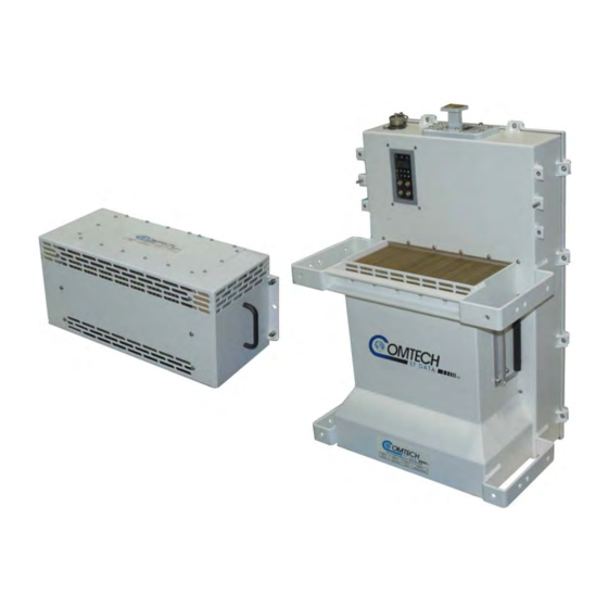
Chapter 1. INTRODUCTION Overview Figure 1-1. Comtech EF Data HPOD SSPA Comtech EF Data’s High‐Power Outdoor (HPOD) Solid‐State Power Amplifier (SSPA) (Figure 1‐1) delivers its rated power, guaranteed, at the 1 dB compression point, to the transmit waveguide flange. It provides a cost effective, more reliable replacement for Traveling Wave Tube Amplifiers (TWTA) in satellite communications. 1–1... -
Page 28: Features
Functional Description Each HPOD consists of a CEFD SSPA module with a field replaceable power supply, a field replaceable fan assembly, and the Monitor/Control Processor (MCP). The amplifier features a Comtech EF Data low loss combining technique and MCP based temperature versus gain ... -
Page 29: Dimensional Envelope
HPOD C-, X-, Ku-Band High-Power Outdoor Amplifier Revision 6 Introduction MN/HPOD.IOM 1.2.1 Dimensional Envelope Figure 1-2. HPOD SSPA Dimensional Envelope 1–3... -
Page 30: Theory Of Operation
HPOD C-, X-, Ku-Band High-Power Outdoor Amplifier Revision 6 Introduction MN/HPOD.IOM Theory of Operation Figure 1‐3 shows the block diagram for the HPOD SSPA. The major components of the unit are the: • SSPA Module. • Power Supply (Power Factor Corrected and Removable/Field Replaceable). • Cooling System. • Monitor and Control (M&C). Figure 1-3. Comtech EF Data HPOD SSPA Block Diagram 1–4... -
Page 31: Sspa Module
HPOD C-, X-, Ku-Band High-Power Outdoor Amplifier Revision 6 Introduction MN/HPOD.IOM 1.3.1 SSPA Module The amplifier module performs the core function of the unit. An isolator is at the RF input to ensure good VSWR. The RF signal then passes through an input sample port and on to an ... -
Page 32: Block Up Converter Input Option
“standard” 14.0 GHz‐to‐14.5 GHz HPOD has an L‐Band frequency range of 1200 MHz‐to‐1700 MHz that translates up to 14.0 GHz‐to‐14.5 GHz, while the “Extended” 13.75 GHz‐to‐14.5 GHz HPOD translates L‐Band frequencies from 950 MHz‐to‐1700 MHz up to 13.75 GHz‐to‐14.5 GHz. Unlike most BUCs, no DC bias voltage should be provided on the center conductor of the L‐Band coax. In addition, the BUC version of the HPOD is available with an internal 10 MHz reference. As, such, no 10 MHz reference is required on the center conductor of the L‐Band coax. If a reference is provided on the coax, the internal reference will detect and lock to it. 1–6... -
Page 33: Specifications
HPOD C-, X-, Ku-Band High-Power Outdoor Amplifier Revision 6 Introduction MN/HPOD.IOM Specifications Output C-Band X-Band Ku-Band 14.0 GHz -to-14.5 GHz (Standard) Frequency 5.850 GHz -to-6.425 GHz 7.9 GHz-to-8.4 GHz 13.75 GHz -to-14.5 GHz (Optional) 200(250) 175(200) 80(100) Available Power: Outputs... - Page 34 HPOD C-, X-, Ku-Band High-Power Outdoor Amplifier Revision 6 Introduction MN/HPOD.IOM Input Impedance 50Ω 8 dB typical, 10 dB maximum @ maximum gain (15 dB for HPOD Ku-Band) Noise Figure with BUC Option 25 dB 1.25:1 Maximum VSWR with BUC Option 1.50:1 Maximum Connector Type ‘N’...
-
Page 35: Chapter 2. External Connectors And Pinouts
(Type ‘N’ shown) Figure 2-1. Coaxial Connector Example The HPOD SSPA uses Type ‘N’ coaxial cables. Type ‘N’ Coaxial cables (plugs) and their mating connectors (jacks/sockets) are available in a threaded coupling style (Figure 2‐1). The jack for this coupling style features external threads. The plug shell features internal threads, and has ... -
Page 36: Hpod Sspa Cabling Connections
Additionally: • Detailed installation and operational information for using HPODs in 1:1 and 1:2 redundancy configurations is provided in Appendix A. REDUNDANCY SYSTEM ASSEMBLY KITS and Appendix B. 1:1 1:2 REDUNDANCY OPERATION. • Information on the HPOD’s M&C operability via serial remote commands and queries is provided in CHAPTER 5. SERIAL‐BASED REMOTE PRODUCT MANAGEMENT. 2–2... -
Page 37: Table 2-1. Hpod Sspa External Connectors
HPOD C-, X-, Ku-Band High-Power Outdoor Amplifier Revision 6 External Connectors and Pinouts MN/HPOD.IOM Figure 2-3. HPOD External Connectors Table 2-1. HPOD SSPA External Connectors Connector Group... -
Page 38: Rf Signal Interface Connector Group
RF Signal Interface Connector Group 2.3.1 J1 | RF IN Connector The J1 | RF IN (Input) connector is a Type ‘N’ female. Typical input levels (‐30 dBm) depend on desired output power and unit attenuation. To prevent damage to the HPOD SSPA, RF input levels should not exceed +15 dBm. 2.3.2 J2 | RF OUT Connector For safety reasons, never look directly into the waveguide output. -
Page 39: Ground And Power Connection Group
HPOD C-, X-, Ku-Band High-Power Outdoor Amplifier Revision 6 External Connectors and Pinouts MN/HPOD.IOM Ground and Power Connection Group 2.4.1 Ground Connection An M4 stud is provided for connecting a common chassis ground among equipment. 2.4.2 J3 | AC IN Connector (AC Power Main) Before applying AC power to the unit, make sure the waveguide output of the amplifier is properly loaded or terminated. -
Page 40: J10 Connector: Optional -48V Dc Power Supply
HPOD C-, X-, Ku-Band High-Power Outdoor Amplifier Revision 6 External Connectors and Pinouts MN/HPOD.IOM 2.4.3 J10 Connector: Optional -48V DC Power Supply Before applying DC power to the unit, make sure the waveguide output of the amplifier is properly loaded or terminated. Failure to do so could lead to equipment damage and excessive RF radiation levels. -
Page 41: Electrical Control Interface Connection Group
HPOD C-, X-, Ku-Band High-Power Outdoor Amplifier Revision 6 External Connectors and Pinouts MN/HPOD.IOM Electrical Control Interface Connection Group 2.5.1 J4 | REDUNDANT LOOP Connector The J4 | REDUNDANT LOOP connector is located near the waveguide output and is used only in configurations where the SSPA controls waveguide switching. In alternate configurations, such as “chain switching”, another system block or external M&C ... -
Page 42: J6 | Com1 Connector
HPOD C-, X-, Ku-Band High-Power Outdoor Amplifier Revision 6 External Connectors and Pinouts MN/HPOD.IOM 2.5.2 J6 | COM1 Connector The J6 | COM1 Discrete Control connector is the primary input for controlling and monitoring the SSPA. It is a 19‐pin circular connector, type MS3112E14‐19S. The pinout specification is shown in Table 2‐6. Mating connector: ITT: KPT06J14‐19P or MS3116J14‐19P. Table 2-6. J6 | COM1 Connector Pinout Name Description RS485_+RX RS485_-RX RS485_+TX RS485_-TX RS232_RD Ethernet TX+... -
Page 43: Energizing The Hpod Sspa
Never turn the unit ON without proper waveguide termination on the J2 RF OUTPUT port. Individuals can be exposed to dangerously high electromagnetic levels. The HPOD SSPA does not contain a ‘Power On/Off’ switch. The SSPA is powered ON by connecting the J3 | AC IN Power connector to the appropriate prime power source. The Mute or Transmit status of the SSPA will automatically come up in the last stored state (factory default = Transmit on, not muted). ... - Page 44 HPOD C-, X-, Ku-Band High-Power Outdoor Amplifier Revision 6 External Connectors and Pinouts MN/HPOD.IOM Notes: 2–10...
-
Page 45: Chapter 3. Updating Firmware
Chapter 3. UPDATING FIRMWARE Introduction TO ENSURE OPTIMAL PERFORMANCE, IT IS IMPORTANT TO OPERATE THE HPOD WITH ITS LATEST AVAILABLE FIRMWARE. Comtech EF Data’s HPOD family of High‐Power Outdoor Amplifiers are factory‐shipped with the latest version of operating firmware. Firmware updates may be applied to an HPOD without having to remove it from operation. If a firmware update is needed, it can be acquired: • By download from the Comtech EF Data Web site (www.comtechefdata.com); • From Comtech EF Data Customer Support during normal business hours, via e‐mail or on CD by standard mail delivery. The HPOD Firmware Update process is as follows: • Download the firmware update archive file via the Internet to a user‐supplied Microsoft ® Windows ‐compatible computer. ... -
Page 46: Getting Started: Preparing For The Firmware Download
HPOD C-, X-, or Ku-Band High-Power Amplifier Revision 6 Updating Firmware MN/HPOD.IOM Getting Started: Preparing for the Firmware Download 1. First, identify the firmware number and its version number. User‐supplied items needed: • A Microsoft Windows‐based PC, equipped with available serial and Ethernet ports; a compatible Web browser (e.g., Internet Explorer); and a terminal emulator program ... - Page 47 HPOD C-, X-, or Ku-Band High-Power Amplifier Revision 6 Updating Firmware MN/HPOD.IOM • Drive letter ‘c:’ is used in these examples. Any valid, writable drive letter can be used. • Typical for all tasks: Type the command without quotes, and then press Enter to execute. There are several ways the user may use create a temporary folder on a Windows‐based PC: A. Use the Windows Desktop to create and rename the temporary folder. • Right‐click anywhere on the desktop to open the popup submenu, and then select New > Folder to create the temporary folder. The new folder will be created on the desktop. • Right‐click on the new folder and then select ‘Rename’ from the popup submenu. ...
- Page 48 HPOD C-, X-, or Ku-Band High-Power Amplifier Revision 6 Updating Firmware MN/HPOD.IOM • Click the Create New Folder icon in the ‘Browse’ window. The new folder will be created. • Right‐click the ‘New Folder’ folder name, and then rename this folder to “temp” or some other convenient, unused name. D. Use Windows Command‐line to create the temporary folder. ...
-
Page 49: Downloading And Extracting The Firmware Update
• About Firmware Numbers, File Versions, and Formats: The Comtech EF Data Web site catalogues its firmware update files by product type (e.g., router, modem, etc.), the specific model, and optional hardware configurations. You should download the HPOD serial (i.e., non‐Ethernet) and/or Ethernet firmware as needed for your setup: o The non‐Ethernet HPOD firmware download hyperlink appears as F12524X_V####. o The Ethernet HPOD firmware download hyperlink appears as ... - Page 50 HPOD C-, X-, or Ku-Band High-Power Amplifier Revision 6 Updating Firmware MN/HPOD.IOM • Some firewalls do not allow the download of *.exe files. Download the *.zip file instead, and extract the firmware files from the archive download with a user‐supplied utility program. For detailed information ...
- Page 51 HPOD C-, X-, or Ku-Band High-Power Amplifier Revision 6 Updating Firmware MN/HPOD.IOM For Ethernet HPOD downloads – extract, at a minimum, two files: ReleaseNotes_HPOD_Ethernet_vX‐X‐X.pdf – Where “X‐X‐X” denotes the firmware version number. FW‐0020544x.bin – Firmware file, where "x" denotes the firmware revision letter. 3. Confirm availability of the firmware files in the temporary folder. There are several ways the user may view the contents of the temporary folder on a ...
-
Page 52: Performing The Ftp Upload Procedures
HPOD C-, X-, or Ku-Band High-Power Amplifier Revision 6 Updating Firmware MN/HPOD.IOM Performing the FTP Upload Procedures To proceed with the firmware update procedure, assumptions are made that: • The HPOD J6 | COM1 port is connected to the user‐supplied, Windows‐based PC serial port or Ethernet port, and • The PC is running a terminal emulation program (for operation of the HPOD serial or Telnet interface) and/or a compatible Web Browser (for operation of the HPOD Web Server Interface). • The latest firmware files have been downloaded or otherwise received from Comtech EF Data and are available on the user PC in an accessible temporary folder. 3.4.1 Performing the Automated Serial-based FTP Upload Procedure 1. - Page 53 ‘Repeat Upload’ or ‘Go Back to Start’ to resume or retry the upload process. 5. Upon successful completion of the upload, you may click on ‘Go Back to Start’ (if, for example, more than one HPOD requires upgrade) or ‘Close’ (to exit the FLSHCAT program). ...
-
Page 54: Performing The Ethernet-Based Ftp Upload Procedure
1. Use Command‐line to send a “PING” command to confirm proper connection and communication between the user PC and the HPOD: • If the IP Address of the HPOD is still not known: o Via Telnet Remote Control – Type the “<1/IPA?” remote query (without quotes) at the command prompt. The HPOD returns the configured IP Address: >0001/IPA=192.168.1.4/24 (default) o Via the HPOD Web Server Interface – View the IP Address/Range entry in the Network Maintenance section of the ‘Admin | Access’ page: • Once the IP Address is known – use Command‐line to PING: ... - Page 55 • Via the HPOD Web Server Interface – Open the ‘Config | Utility’ page and review the SC/13320 Board Firmware Version section to verify that the PC‐to‐Unit FTP file transfer was successful. 4. Use the HPOD Web Server Interface to select the boot image. To select the desired boot Image, open the HPOD Web Server Interface ‘Config | Utility’ page. Use the Next Reboot Image drop‐down list in the Current SC/13320 Active Firmware Image # section to select 1 or 2, and then click [Submit]. 5. Reboot the HPOD. A. Disconnect the power source from the HPOD. B. Re‐energize the HPOD. The unit will reboot using the updated firmware image. ...
- Page 56 HPOD C-, X-, or Ku-Band High-Power Amplifier Revision 6 Updating Firmware MN/HPOD.IOM Notes: 3–12...
- Page 57 Chapter 4. ETHERNET-BASED REMOTE PRODUCT MANAGEMENT Introduction This chapter describes the functionality of the HPOD Ethernet (HTTP) Interface. Ethernet‐based Remote Product Management of the HPOD is available using the J6 | COM1 port. To proceed with Ethernet‐based Remote Product Management, assumptions are made that: • The HPOD is operating with the latest version firmware files. • The HPOD is connected to a user‐supplied Windows‐based PC as follows: o The PC’s Ethernet port is connected to the HPOD J6 | COM1 port with a 190‐pin to RJ‐45 adapter cable. ...
-
Page 58: Chapter 4. Ethernet-Based Remote Product Management
OID: 1.3.6.1.4.1.6247 Full path: iso(1).org(3).dod(6).internet(1).private(4).enterprises(1).comtechEFData(6247) Module: ComtechEFData FW-0020547x.mib MIB file consists of all of the OIDs for management of the HPOD functions HPOD MIB file FW-0020548x.mib Trap MIB file is provided for SNMPv1 traps common for HPOD. HPOD Traps MIB file ... -
Page 59: Snmp Community Strings
Read Community default = public • Write Community default = private • Trap Community default = comtech For proper SNMP operation, the HPOD MIB files must be used with the associated version of the HPOD M&C. Please refer to the HPOD FW Release Notes for information on the required FW/SW compatibility. 4.3.3 SNMP Traps The HPOD sends out SNMP traps both when a fault occurs and when it is cleared. 1. The SNMP agent supports SNMP v1 and v2c. If SNMP v1 traps are to be used, then make sure to compile the traps file. Use the hpodSNMPTrapVersion OID to configure the type of traps that the HPOD will send. The HPOD uses these MIB2 v1 traps and v2 notifications: ... -
Page 60: Telnet Interface
62476216 hpodSummaryFault 1.3.6.1.4.1.6247.62.1.3.1.16 Telnet Interface The HPOD has a Telnet interface for the equipment M&C operations. Log in to the Telnet interface at the Administrator level or Read/Write level. An example of the login process is shown here: ... -
Page 61: Telnet Operation Via Hyperterminal
HPOD C, X-, or Ku-Band High-Power Outdoor Amplifier Revision 6 Ethernet-based Remote Product Management MN/HPOD.IOM 4.4.1 Telnet Operation via HyperTerminal There is a disadvantage when using Windows Command‐line as a Telnet client. Since Command‐ line cannot translate a ‘\r’ (i.e., carriage return or “CR”) to a ‘\r\n’ (i.e., CR+line feed “LF”) for the messages coming from Telnet Server, any multi‐line Target‐to‐Controller response (e.g., the response to the FRW? query) will be displayed as one line, with the latter lines overwriting the previous lines. In order to view the full response messages, Comtech EF Data recommends use of the ... -
Page 62: Hpod Web Server (Http) Interface
HPOD Web Server (HTTP) Interface A user‐supplied web browser allows the full monitor and control (M&C) of the HPOD from its embedded Web Server Interface. This application is designed for, and works best with, Microsoft’s Internet Explorer Version 5.5 or higher. 4.5.1 Enabling the Web Server Interface Follow these steps to enable the HPOD Web Server Interface using only a 10/100BaseT remote ... - Page 63 HPOD C, X-, or Ku-Band High-Power Outdoor Amplifier Revision 6 Ethernet-based Remote Product Management MN/HPOD.IOM 3. Enter the User name and password (the default for both is comtech): 4. Use the LRS remote command to set the Ethernet remote control access parameter: • Use default remote command LRS=3 for Serial + Ethernet control • Use remote command LRS=2 for Ethernet control only. ...
-
Page 64: User Login
HPOD C, X-, or Ku-Band High-Power Outdoor Amplifier Revision 6 Ethernet-based Remote Product Management MN/HPOD.IOM 4.5.2 User Login Follow these steps to log in to the HPOD Web Server Interface using a compatible web browser. 1. On the PC, type http://192.168.1.4 (the default IP address for the HPOD) into the browser’s Address area, and then press [Enter]. 2. The Login window will appear, similar to the example shown ... -
Page 65: Web Server Interface - Operational Features
HPOD C, X-, or Ku-Band High-Power Outdoor Amplifier Revision 6 Ethernet-based Remote Product Management MN/HPOD.IOM 4.5.3 Web Server Interface – Operational Features 4.5.3.1 Navigation Navigation tabs are located at the top of each page. After you click a navigation tab, its nested page hyperlinks appear. This manual shows page navigation and hyperlink selection in the format ‘Top‐Level Navigation Tab | Nested Page Hyperlink.’ For example: ‘Home | Support’ is interpreted to mean “first click the top‐level ‘Home’ navigation tab; then, click the nested ‘Support’ page hyperlink.” 4.5.3.2 Page Sections Each page features one or more sections. The title at the upper‐left ... -
Page 66: Text Or Data Entry
If you go to another page without first clicking the action button, your changes are not saved. 4.5.4 Web Server Interface – Menu Tree The HPOD Web Server Interface features four (4) navigation tabs at the top of each page. Nested hyperlinks (shown in gray) grant access to individual Web pages. ... -
Page 67: Home Pages
HPOD C, X-, or Ku-Band High-Power Outdoor Amplifier Revision 6 Ethernet-based Remote Product Management MN/HPOD.IOM 4.5.5.1 Home Pages Click the Home tab, and then select the Home, Contact, or Support hyperlink to continue. 4.5.5.1.1 Home | Home Page Use this page to identify the product in use and its current firmware version. Click the Home navigation tab and/or the nested hyperlink to return to this page from anywhere in the Web Server Interface. ... - Page 68 HPOD C, X-, or Ku-Band High-Power Outdoor Amplifier Revision 6 Ethernet-based Remote Product Management MN/HPOD.IOM 4.5.5.1.2 Home | Contact Page Use this page to see the contact information (phone, fax, or Web/e‐mail hyperlinks) for Comtech EF Data Sales or Customer Support. ...
- Page 69 HPOD C, X-, or Ku-Band High-Power Outdoor Amplifier Revision 6 Ethernet-based Remote Product Management MN/HPOD.IOM 4.5.5.1.3 Home | Support Page The HPOD administrator must first set the SMTP (Simple Mail Transport Protocol) server, domain name, and destination on the Admin | Access page (see Sect. 4.5.5.2.1) before this page is functional. ...
-
Page 70: Admin Pages
Only users logged in with the Administrator name and password have access to these pages. Click the Admin tab, and then select the Access or SNMP hyperlink to continue. 4.5.5.2.1 Admin | Access Page The Administrator must use this page to manage the HPOD Web Server Interface access settings. ... - Page 71 HPOD C, X-, or Ku-Band High-Power Outdoor Amplifier Revision 6 Ethernet-based Remote Product Management MN/HPOD.IOM The MAC Address is read‐only. It is set at the factory to a guaranteed unique address and cannot be modified. System Account Access Information • Read Only / Read/Write / Admin Names and Passwords – These defaults, set at the factory, may be changed as needed: Factory Default Maximum Field Format Name / Password Characters Read Only Name / Password...
- Page 72 HPOD C, X-, or Ku-Band High-Power Outdoor Amplifier Revision 6 Ethernet-based Remote Product Management MN/HPOD.IOM 4.5.5.2.2 Admin | SNMP Page Sect. 4.3 SNMP INTERFACE The Administrator must use this page to manage the HPOD SNMP (Simple Network Management Protocol) settings. ...
-
Page 73: Config Pages
HPOD C, X-, or Ku-Band High-Power Outdoor Amplifier Revision 6 Ethernet-based Remote Product Management MN/HPOD.IOM • Trap IP 1 / Trap IP 2 – The Administrator can assign up to two SNMP Trap IP addresses in the form 000.000.000.000. • Trap Version – Use the drop‐down list to select the SNMP Trap as version SNMPv1 or SNMPv2c. Click [Submit SNMP] to save these changes, or click [Reset] to revert to the previously assigned SNMP settings. ... - Page 74 HPOD C, X-, or Ku-Band High-Power Outdoor Amplifier Revision 6 Ethernet-based Remote Product Management MN/HPOD.IOM • Amplifier – Use the drop‐down list to set the amplifier as On or Off. • Mute – Use the drop‐down list to set the Mute function as Enabled or Disabled. Click [Change Configuration] to save these settings, or click [Reset] to revert to the previously assigned Amplifier settings. Fault Recovery Use the drop‐down list to set Fault Recovery as Automatic or Manual, and then click [Change]. BUC Mute Use the drop‐down list to set BUC Mute as Muted or Not Muted, and then click [Change]. Reference Adjust Enter a numeric value from 0 to 255 to set the reference oscillator tuning voltage. The default voltage value is 87. Click [Change] when done. Serial • Remote Address – Enter a physical remote address from 0001 to 9999. • Baud Rate – Use the drop‐down list to set the operating baud rate as 9600 or 19200 bps. Click [Change Serial Configuration] to save these settings.
-
Page 75: Date And Time
HPOD C, X-, or Ku-Band High-Power Outdoor Amplifier Revision 6 Ethernet-based Remote Product Management MN/HPOD.IOM 4.5.5.3.2 Config | Utility Page Use this page to configure HPOD operating parameters. Figure 4-7. Config | Utility page At any time, click [Refresh] to update this page and see the most recent data. ... - Page 76 HPOD C, X-, or Ku-Band High-Power Outdoor Amplifier Revision 6 Ethernet-based Remote Product Management MN/HPOD.IOM SC/13320 Board Firmware Version (read-only) This read‐only section identifies the current Boot, Bulk1, and Bulk2 firmware loads. 4.5.5.3.3 Config | Redundancy Page See Appendix B. 1:1 AND 1:2 REDUNDANCY OPERATION for details on using age to configure the HPOD for redundant operations. this p ...
-
Page 77: Status Pages
HPOD C, X-, or Ku-Band High-Power Outdoor Amplifier Revision 6 Ethernet-based Remote Product Management MN/HPOD.IOM 4.5.5.4 Status Pages Use the ‘Status’ pages for updates on the HPOD’s operational status, logged alarms, and Field Effect Transistor (FET) operating currents. Click the Status tab, and then select the Monitor, Alarms, or FETs hyperlink to continue. 4.5.5.4.1 Status | Monitor Page Use this page to monitor the operating status of the HPOD unit. ... - Page 78 HPOD C, X-, or Ku-Band High-Power Outdoor Amplifier Revision 6 Ethernet-based Remote Product Management MN/HPOD.IOM 4.5.5.4.2 Status | Alarms Page Use this page to view and manage logged alarms data. Figure 4-10. Status | Alarms page At any time, click [Refresh] to update this page and see the most recent data. Unread Stored Alarms: ## This read‐only scrollable display lists unread stored alarms in sequential, date‐stamped format. The unit returns and displays the five oldest stored alarms in the log. All alarms that are read ...
- Page 79 HPOD C, X-, or Ku-Band High-Power Outdoor Amplifier Revision 6 Ethernet-based Remote Product Management MN/HPOD.IOM 4.5.5.4.3 Status | FETs Page Use this read‐only page to see the operating currents of all Field Effect Transistors (FETs) installed in the RF amplifier. ...
- Page 80 HPOD C, X-, or Ku-Band High-Power Outdoor Amplifier Revision 6 Ethernet-based Remote Product Management MN/HPOD.IOM Notes: ...
-
Page 81: Chapter 5. Serial-Based Remote Product Management
Chapter 5. SERIAL-BASED REMOTE PRODUCT MANAGEMENT Overview This chapter describes the protocol and message command and query set for complete remote monitor and control of the HPOD SSPA. It also summarizes key operational parameters and some of their most commonly‐used remote commands and queries. Key Operational Parameters See Sect.5.5 Remote Commands and Queries for detailed information about the remote commands and queries mentioned in this section. 5.2.1 RF Input Level The individual amplifier maximum gain and power rating determines the RF input level required to reach the full rated output power of the HPOD. For example: If the test data of an SSPA rated for 250W (54 dBm) indicated a gain of 75 dB, then a signal of 54dBm – 75 dB = ‐21 dBm would approximately give the rated output power. Increasing input power beyond this level results in an output signal with increasingly higher levels of distortion. Of course, if the SSPA attenuation control is utilized, a higher‐level input signal level can be accommodated. 5–1... -
Page 82: Attenuator Control
HPOD C-, X-, Ku-Band High-Power Outdoor Amplifier Revision 6 Serial-Based Remote Product Management MN/HPOD.IOM Permanent damage may occur to the unit if the maximum input level exceeds 15 dBm. 5.2.2 Attenuator Control Execute the “ATT” command to attenuate HPOD gain over a 30 dB range. 5.2.3 Mute Control The amplifier may be muted via software or discrete control: • Execute the MUT=1 command to “software” mute the unit. The Mute command provides over 75 dB of RF on/off isolation. ... -
Page 83: Power Detector
HPOD C-, X-, Ku-Band High-Power Outdoor Amplifier Revision 6 Serial-Based Remote Product Management MN/HPOD.IOM • Thermal Shutdown. The system indicates a temperature fault if the unit is ≥ +95°C. This creates a summary fault and causes the unit to mute itself, and switch to the backup unit if in a redundancy system. However, the 10V supply to the Field Effect Transistors (FETs) will remain on until the unit reaches the thermal shutdown temperature of ≥ 100°C. For protection reasons, ... -
Page 84: Basic Protocol
HPOD C-, X-, Ku-Band High-Power Outdoor Amplifier Revision 6 Serial-Based Remote Product Management MN/HPOD.IOM It is assumed that a 'Controller' device (a PC or ASCII dumb terminal) transmits data in a broadcast mode via one of the pairs. Multiple 'Target' devices are connected to this pair, and all simultaneously receive data from the Controller. The Controller is the only device with a line‐driver connected to this pair – the Target devices have only line‐receivers connected. In the other direction, on the other pair each Target has a Tri‐state line driver connected, and the Controller has a line‐receiver ... -
Page 85: Packet Structure
HPOD C-, X-, Ku-Band High-Power Outdoor Amplifier Revision 6 Serial-Based Remote Product Management MN/HPOD.IOM All bytes within a packet are printable ASCII characters, less than ASCII code 127. In this context, the Carriage Return and Line Feed characters are considered printable. All messages from Controller‐to‐Target require a response, with one exception: This will be either to return data that has been ... -
Page 86: Start Of Packet
HPOD C-, X-, Ku-Band High-Power Outdoor Amplifier Revision 6 Serial-Based Remote Product Management MN/HPOD.IOM 5.3.4.1 Start of Packet • Controller‐to‐Target – This is the character ‘<’ (ASCII code 60). • Target‐to‐Controller – This is the character ‘>’ (ASCII code 62). The ‘<’ and ‘>’ characters indicate the start of packet. They may not appear anywhere else within the body of the message. 5.3.4.2 Target Address Up to 9,999 devices can be uniquely addressed; in both EIA‐485 and EIA‐232 applications, the permissible range of values is 1 to 9999. The address is programmed into a Target unit using the remote control port. The Controller sends a packet with the address of a Target – the destination of the packet. When the Target responds, the address used is the same address, to indicate to the Controller the source of the packet. - Page 87 HPOD C-, X-, Ku-Band High-Power Outdoor Amplifier Revision 6 Serial-Based Remote Product Management MN/HPOD.IOM Character Definition This character is used as the Assignment Operator (AO). It establishes that the Instruction Code that precedes it is to be used as a (ASCII code 61) command to assign or configure operation.
-
Page 88: Optional Message Arguments
HPOD C-, X-, Ku-Band High-Power Outdoor Amplifier Revision 6 Serial-Based Remote Product Management MN/HPOD.IOM 5.3.4.6 Optional Message Arguments Arguments are not required for all messages. Arguments are ASCII codes for the characters ‘0’ to ‘9’ (ASCII codes 48 to 57), period ‘.’ (ASCII code 46), and comma ‘,’ (ASCII code 44). 5.3.4.7 End of Packet • Controller‐to‐Target – This is the ‘Carriage Return’ ([CR]) character (ASCII code 13). • Target‐to‐Controller – This is the two‐character sequence ‘Carriage Return’, ‘Line Feed’ ([cr][lf]) (ASCII codes 13 and 10). Both indicate the valid termination of a packet. 5–8... -
Page 89: Remote Commands And Queries
HPOD C-, X-, Ku-Band High-Power Outdoor Amplifier Revision 6 Serial-Based Remote Product Management MN/HPOD.IOM Remote Commands and Queries Index Notes: Column ‘C’ = Command; Column ‘Q’ = Query; columns marked ‘X’ designate instruction code as Command only, Query only, or Command/Query. Instr Code Page Instr Code Page Instr Code Page 5-10 5-10 5–188 5-10 5–177 5–189 5-10 5–188 5–189 5–1010 5–188 5–144... - Page 90 HPOD C-, X-, Ku-Band High-Power Outdoor Amplifier Revision 6 Serial-Based Remote Product Management MN/HPOD.IOM Command Query Parameter Number of Response to (Instruction Description of Arguments (Instruction Response to Query Type Arguments Command & Qualifier) & Qualifier) Auto Fault AFR= 1 byte, Command or Query.
- Page 91 HPOD C-, X-, Ku-Band High-Power Outdoor Amplifier Revision 6 Serial-Based Remote Product Management MN/HPOD.IOM Command Query Parameter Number of Response to (Instruction Description of Arguments (Instruction Response to Query Type Arguments Command & Qualifier) & Qualifier) Clear All Stored CAA= None Command only.
- Page 92 HPOD C-, X-, Ku-Band High-Power Outdoor Amplifier Revision 6 Serial-Based Remote Product Management MN/HPOD.IOM Command Query Parameter Number of Response to (Instruction Description of Arguments (Instruction Response to Query Type Arguments Command & Qualifier) & Qualifier) Concise RF Variable length Query only.
- Page 93 HPOD C-, X-, Ku-Band High-Power Outdoor Amplifier Revision 6 Serial-Based Remote Product Management MN/HPOD.IOM Command Query Parameter Number of Response to (Instruction Description of Arguments (Instruction Response to Query Type Arguments Command & Qualifier) & Qualifier) Set RTC (Real- DAT= 6 bytes, Command or Query.
- Page 94 HPOD C-, X-, Ku-Band High-Power Outdoor Amplifier Revision 6 Serial-Based Remote Product Management MN/HPOD.IOM Command Query Parameter Number of Response to (Instruction Description of Arguments (Instruction Response to Query Type Arguments Command & Qualifier) & Qualifier) Retrieve next 5 145 bytes, Query only.
- Page 95 HPOD C-, X-, Ku-Band High-Power Outdoor Amplifier Revision 6 Serial-Based Remote Product Management MN/HPOD.IOM Command Query Parameter Number of Response to (Instruction Description of Arguments (Instruction Response to Query Type Arguments Command & Qualifier) & Qualifier) Retrieve Alarm 117 bytes, Query only.
- Page 96 HPOD C-, X-, Ku-Band High-Power Outdoor Amplifier Revision 6 Serial-Based Remote Product Management MN/HPOD.IOM Command Query Parameter Number of Response to (Instruction Description of Arguments (Instruction Response to Query Type Arguments Command & Qualifier) & Qualifier) Reference REF= 3 bytes, Command or Query.
- Page 97 HPOD C-, X-, Ku-Band High-Power Outdoor Amplifier Revision 6 Serial-Based Remote Product Management MN/HPOD.IOM Command Query Parameter Number of Response to (Instruction Description of Arguments (Instruction Response to Query Type Arguments Command & Qualifier) & Qualifier) Retrieve 168 bytes, Query only.
- Page 98 HPOD C-, X-, Ku-Band High-Power Outdoor Amplifier Revision 6 Serial-Based Remote Product Management MN/HPOD.IOM Command Query Parameter Number of Response to (Instruction Description of Arguments (Instruction Response to Query Type Arguments Command & Qualifier) & Qualifier) Summary Fault 1 byte, Query only.
- Page 99 HPOD C-, X-, Ku-Band High-Power Outdoor Amplifier Revision 6 Serial-Based Remote Product Management MN/HPOD.IOM Command Query Parameter Number of Response to (Instruction Description of Arguments (Instruction Response to Query Type Arguments Command & Qualifier) & Qualifier) IP Address IPA= 18 bytes Command or Query.
- Page 100 HPOD C-, X-, Ku-Band High-Power Outdoor Amplifier Revision 6 Serial-Based Remote Product Management MN/HPOD.IOM Notes: 5–20...
-
Page 101: Appendix A. Redundancy System Assembly Kits
Appendix A. REDUNDANCY SYSTEM ASSEMBLY KITS Introduction Several kits are available from Comtech EF Data to mount and install HPOD 1:1 or 1:2 Redundancy Systems, tailored to the operational frequency of the system. The figures and tables provided in the subsections that follow provide examples of these currently available kits. Once all system kit components have been assembled, and all interconnecting RF and M&C cables have been installed, see Appendix B. 1:1 AND 1:2 REDUNDANCY OPERATION for further information about configuring, operating, and troubleshooting your HPOD 1:1 or 1:2 Redundancy System. A–1... -
Page 102: Table A-1. Summary Of Available Redundancy System Assembly Kits
ODPA C-Band 1:1 Redundancy Switch/Waveguide Kit A-11 KT/11387 ODPA X-Band 1:1 Redundancy Switch/Waveguide Kit – A-12 KT/12240-1 HPOD 1:1 C-Band Redundancy System – Switch and Unistrut Assembly 1:1 Kits A-13 KT/12201-1 HPOD C-Band 1:1 Redundancy Switch/Waveguide Kit A-14 KT-0020523 HPOD C-Band Offline Unit Termination Bypass Waveguide Kit... - Page 103 HPOD C-, X-, Ku-Band High-Power Outdoor Amplifier Revision 6 Appendix A MN/HPOD.IOM Notes: A–3...
-
Page 104: Common Mounting Kits
HPOD C-, X-, Ku-Band High-Power Outdoor Amplifier Revision 6 Appendix A MN/HPOD.IOM Common Mounting Kits Table A-2. Universal Pole Mounting Kit (CEFD P/N PL/12319-1) Parts List ITEM CEFD P/N DESCRIPTION DUAL CHANNEL UNISTRUT (P/O MOUNTING KIT, SHOWN FOR REFERENCE ONLY) - Page 105 HPOD C-, X-, Ku-Band High-Power Outdoor Amplifier Revision 6 Appendix A MN/HPOD.IOM Figure A-1. Universal Pole Mounting Kit (CEFD P/N PL/12319-1) A–5...
-
Page 106: Table A-3. Hpod Unit Mounting Kit (Cefd P/N Pl/12300-1) Parts List
HPOD C-, X-, Ku-Band High-Power Outdoor Amplifier Revision 6 Appendix A MN/HPOD.IOM Table A-3. HPOD Unit Mounting Kit (CEFD P/N PL/12300-1) Parts List ITEM CEFD P/N DESCRIPTION FP/BR12239-1 Bracket, Mounting (ROHS) HW/3/8SPRINGNUT Springnut HW/3/8-FLT Washer, Flat HW/3/8-SPLIT Washer, Split... - Page 107 Figure A-2. HPOD Unit Mounting Kit (CEFD P/N PL/12300-1) A–7...
-
Page 108: Table A-4. Hpod 1:1 Redundancy System - Common Unistrut Kit (Cefd P/N Kt/12200-1) Parts List
HPOD C-, X-, Ku-Band High-Power Outdoor Amplifier Revision 6 Appendix A MN/HPOD.IOM Table A-4. HPOD 1:1 Redundancy System – Common Unistrut Kit (CEFD P/N KT/12200-1) Parts List ITEM CEFD P/N DESCRIPTION FP/BR11931-1 Dual Channel Unistrut FP/BR11932-1 Bracket, Channel Not Used... - Page 109 Figure A-3. HPOD 1:1 Redundancy System – Common Unistrut Kit (CEFD P/N KT/12200-1) A–9...
-
Page 110: Table A-5. Hpod 1:2 Redundancy System - Common Unistrut Kit (Cefd P/N Kt-0000017) Parts List
HPOD C-, X-, Ku-Band High-Power Outdoor Amplifier Revision 6 Appendix A MN/HPOD.IOM Table A-5. HPOD 1:2 Redundancy System – Common Unistrut Kit (CEFD P/N KT-0000017) Parts List ITEM CEFD P/N DESCRIPTION FP-0000134 Unistrut, Dual Channel FP/BR11932-1 Bracket, Unistrut Not Used... - Page 111 HPOD C-, X-, Ku-Band High-Power Outdoor Amplifier Revision 6 Appendix A MN/HPOD.IOM Figure A-4. HPOD 1:2 Redundancy System – Common Unistrut Kit (CEFD P/N KT-0000017) A–11...
-
Page 112: 1:1 Redundancy System Mounting And Switch Kits
HPOD C-, X-, Ku-Band High-Power Outdoor Amplifier Revision 6 Appendix A MN/HPOD.IOM 1:1 Redundancy System Mounting and Switch Kits ... - Page 113 HPOD C-, X-, Ku-Band High-Power Outdoor Amplifier Revision 6 Appendix A MN/HPOD.IOM Figure A-6. Typical 1:1 Mounting and Switch Kit Example – Assembled Isometric View...
- Page 114 HPOD C-, X-, Ku-Band High-Power Outdoor Amplifier Revision 6 Appendix A MN/HPOD.IOM Figure A-7. Typical 1:1 Mounting and Switch Kit Example – Top View A–14...
- Page 115 HPOD C-, X-, Ku-Band High-Power Outdoor Amplifier Revision 6 Appendix A MN/HPOD.IOM Figure A-8. Typical 1:1 Mounting and Switch Kit Example – Front View A–15...
- Page 116 HPOD C-, X-, Ku-Band High-Power Outdoor Amplifier Revision 6 Appendix A MN/HPOD.IOM Figure A-9. Typical 1:1 Mounting and Switch Kit Example – Side View A–16...
- Page 117 HPOD C-, X-, Ku-Band High-Power Outdoor Amplifier Revision 6 Appendix A MN/HPOD.IOM This page is intentionally blank. ...
-
Page 118: Table A-6. Odpa C-Band 1:1 Redundancy Switch/Waveguide Kit (Cefd P/N Kt/11799) Parts List
HPOD C-, X-, Ku-Band High-Power Outdoor Amplifier Revision 6 Appendix A MN/HPOD.IOM Table A-6. ODPA C-Band 1:1 Redundancy Switch/Waveguide Kit (CEFD P/N KT/11799) Parts List ITEM CEFD P/N DESCRIPTION SW/WGS+28V137SC Waveguide, CPR137, 28V, Sealed 3 Form C Relay FP/BR11798-1 Bracket, Switch and Load Mounting... - Page 119 HPOD C-, X-, Ku-Band High-Power Outdoor Amplifier Revision 6 Appendix A MN/HPOD.IOM ...
-
Page 120: Table A-7. Odpa X-Band 1:1 Redundancy Switch/Waveguide Kit (Cefd P/N Kt/11387-1) Parts List
HPOD C-, X-, Ku-Band High-Power Outdoor Amplifier Revision 6 Appendix A MN/HPOD.IOM Table A-7. ODPA X-Band 1:1 Redundancy Switch/Waveguide Kit (CEFD P/N KT/11387-1) Parts List ITEM CEFD P/N DESCRIPTION Not Used Not Used RF/CG-112/137INN Crossguide Coupler, 40 dB, Type N Connector,137-112... - Page 121 HPOD C-, X-, Ku-Band High-Power Outdoor Amplifier Revision 6 Appendix A MN/HPOD.IOM Figure A-11. ODPA X-Band 1:1 Redundancy Switch/Waveguide Kit (CEFD P/N KT/11387-1) A–21...
- Page 122 DESCRIPTION REF TABLE REF FIGURE KT/12201-1 HPOD C-Band 1:1 Redundancy Switch/Waveguide Kit (ROHS) A-13 KT/12200-1 HPOD 1:1 Redundancy System – Common Unistrut Kit Figure A-12. HPOD C-Band 1:1 Redundancy System – Switch and Unistrut Assembly (CEFD P/N KT/12240-1) A–22...
-
Page 123: Table A-8. Hpod C-Band 1:1 Redundancy Switch/Waveguide Kit (Cefd P/N Kt/12201-1) Parts List
HPOD C-, X-, Ku-Band High-Power Outdoor Amplifier Revision 6 Appendix A MN/HPOD.IOM Table A-8. HPOD C-Band 1:1 Redundancy Switch/Waveguide Kit (CEFD P/N KT/12201-1) Parts List ITEM CEFD P/N DESCRIPTION FP/BR12242-1 Bracket, Mounting (ROHS) GA/CPA-137-R-H-C Gasket, Half-Thickness GA/CPR-137-R-F-C Gasket, Full-Thickness RF/C-TERM1000W... - Page 124 Figure A-13. HPOD C-Band 1:1 Redundancy Switch/Waveguide Kit (CEFD P/N KT/12201-1) A–24...
-
Page 125: Table A-9. Hpod C-Band Offline Unit Termination Bypass Waveguide Kit (Cefd P/N Kt-0020523) Parts List
HPOD C-, X-, Ku-Band High-Power Outdoor Amplifier Revision 6 Appendix A MN/HPOD.IOM Table A-9. HPOD C-Band Offline Unit Termination Bypass Waveguide Kit (CEFD P/N KT-0020523) Parts List ITEM CEFD P/N DESCRIPTION FP/BR12242-1 Bracket, Mount (ROHS) SW/WG-3NFAS-COLD Switch, CPR 137 FP/WG10359-1... - Page 126 Figure A-14. HPOD C-Band Offline Unit Termination Bypass Waveguide Kit (CEFD P/N KT-0020523) A–26...
-
Page 127: Table A-10. Ku-Band 1:1 Redundancy Assembly Kit (Cefd P/N Kt/11936-1) Parts List
HPOD C-, X-, Ku-Band High-Power Outdoor Amplifier Revision 6 Appendix A MN/HPOD.IOM Table A-10. Ku-Band 1:1 Redundancy Assembly Kit (CEFD P/N KT/11936-1) Parts List ITEM CEFD P/N DESCRIPTION SW/WGS+28V-75SB Switch, +28VDC FP/WG11825-1 Waveguide, Straight FP/WG11935-1 Waveguide, Right FP/WG11934-1 Waveguide, Left... - Page 128 HPOD C-, X-, Ku-Band High-Power Outdoor Amplifier Revision 6 Appendix A MN/HPOD.IOM Figure A-15. Ku-Band 1:1 Redundancy Assembly Kit (CEFD P/N KT/11936-1)
-
Page 129: Table A-11. Hpod Ku-Band 1:1 Redundancy Switch/Waveguide Kit (Cefd P/N Kt/12337-1) Parts List
HPOD C-, X-, Ku-Band High-Power Outdoor Amplifier Revision 6 Appendix A MN/HPOD.IOM Table A-11. HPOD Ku-Band 1:1 Redundancy Switch/Waveguide Kit (CEFD P/N KT/12337-1) Parts List ITEM CEFD P/N DESCRIPTION SW/WGS+28V-75SB Switch, Waveguide RF/TERM75/350W Waveguide, Termination FP/BR12338-1 Bracket, Mounting (ROHS) FP/WG11934-1... - Page 130 Figure A-16. HPOD Ku-Band 1:1 Redundancy Switch/Waveguide Kit (CEFD P/N KT/12337-1) A–30...
- Page 131 HPOD C-, X-, Ku-Band High-Power Outdoor Amplifier Revision 6 Appendix A MN/HPOD.IOM This page is intentionally blank. A–31...
-
Page 132: 1:2 Redundancy System Mounting And Switch Kit Examples
Figure A-17. HPOD C-Band 1:2 Redundancy System – Isometric View A–32... - Page 133 HPOD C-, X-, Ku-Band High-Power Outdoor Amplifier Revision 6 Appendix A MN/HPOD.IOM Figure A-18. HPOD C-Band 1:2 Redundancy System – Top View ...
- Page 134 Figure A-20. HPOD C-Band 1:2 Redundancy System – Front View Switch Detail ‘A’ and Side View A–34...
- Page 135 HPOD C-, X-, Ku-Band High-Power Outdoor Amplifier Revision 6 Appendix A MN/HPOD.IOM Figure A-21. HPOD C-Band 1:2 Redundancy System – Back View A–35...
- Page 136 HPOD C-, X-, Ku-Band High-Power Outdoor Amplifier Revision 6 Appendix A MN/HPOD.IOM Notes: A–36...
-
Page 137: Appendix B. 1:1 And 1:2 Redundancy Operation
Appendix B. 1:1 AND 1:2 REDUNDANCY OPERATION Introduction Comtech EF Data’s C‐, X‐, and KU‐Band High‐Power Outdoor Power Amplifiers (HPODs) can be used in redundant configuration by connecting the appropriate redundancy loop cable between the user M&C location and each HPOD ‘J4 | REDUNDANT LOOP’ port. This 1:1 or 1:2 cable has connector pinouts that allow the HPODs to both automatically detect the type of cable in use and, when properly connected between the user and the redundancy setup, automatically configure itself for operations in accordance with the labeling for each cable connector (SSPA 1 or SSPA 2 for a 1:1 system, or SSPA 1, SSPA 2, or SSPA BU for a 1:2 system). B.1.1 1:1 Redundancy Mode In 1:1 redundancy mode, the unit that is currently not the active unit (determined by the switch position) will be the controlling Backup Unit (BU). The redundancy system’s operating mode is determined by using the “RAM” serial remote ... - Page 138 HPOD C-, X-, Ku-Band High-Power Outdoor Amplifier Revision 6 Appendix B MN/HPOD.IOM In 1:1 applications, the BU also stores an offset value, to be used when the BU replaces the active unit. This offset may be set with the GOF= command. When the online unit is being ...
- Page 139 Figure B-1. HPOD C-Band 1:2 Redundancy System Block Diagram In 1:2 redundancy mode there is a dedicated BackupUnit (designated as BU) as determined by the cable position. In this configuration, the BU is responsible for monitoring the two online units for communications and summary faults. While the BU is constantly monitoring both units for their status, if either has a fault, use the last (good) status as the configuration for the BU before the BU goes online. Once the BU goes ...
- Page 140 HPOD C-, X-, Ku-Band High-Power Outdoor Amplifier Revision 6 Appendix B MN/HPOD.IOM different than the attenuation value of the online unit to compensate for any gain mismatch between the BU and online units. To calibrate: 1. After proper operating levels have been established in online SSPA 1 and 2, store their ...
-
Page 141: Redundancy Operation Using The Hpod Web Server Interface
B.2.1 HPOD Web Server Interface Overview To use the HPOD Web Server Interface: • Open a compatible Web browser. • Enter the HPOD IP Address into the browser Address field (default is http://192.168.1.4) • Enter a valid user name / password (default is comtech / comtech). The HPOD Web Server Interface ‘Home’ page appears upon successful login: ... - Page 142 HPOD C-, X-, Ku-Band High-Power Outdoor Amplifier Revision 6 Appendix B MN/HPOD.IOM The HPOD Web Server Interface features four (4) navigation tabs at the top of each page. Nested hyperlinks (shown in gray) grant access to individual Web pages. The hyperlink for the Redundancy page is available under the Config tab. Home Access Amplifier Monitor Contact SNMP Utility...
- Page 143 Gain Offset (1:1 only) Enter the gain offset, in 0.25 dB steps, and then click [Change]. Force Back-up State (1:2 only) Use the drop‐down list to set the back‐up state as follows: • Select Unit 01 or Unit 02 to put that HPOD into an offline state and set the Redundancy Mode to Manual. • Select None to put the backup unit offline and set the Redundancy Mode to Automatic. Click [Change] to save this setting. Backup Offset for Unit 01 (1:2 only) Enter the Backup Offset for Unit 01, in 0.25 dB steps, and then click [Change].
-
Page 144: Redundancy Operation Using Serial-Based Remote Commands And Queries
HPOD C-, X-, Ku-Band High-Power Outdoor Amplifier Revision 6 Appendix B MN/HPOD.IOM Redundancy Operation using Serial-based Remote Commands and Queries See Chapter 5. SERIAL-BASED REMOTE PRODUCT MANAGEMENT for detailed information about using the HPOD EIA-485/232 serial interface. Index Notes: Columns marked ‘X’ designate instruction code or system compatibility as follows: ... - Page 145 HPOD C-, X-, Ku-Band High-Power Outdoor Amplifier Revision 6 Appendix B MN/HPOD.IOM Command Arguments for Response to Query Response to Parameter (Instruction Command or Description of Arguments Command (Instruction query Type Code and Response to (Note that all arguments are ASCII numeric codes – i.e., ASCII codes between 48 and 57)
-
Page 146: Hpod Series 1:1 Redundancy Test
B.4.1 Connection Step Task Connect HPOD redundancy loop connectors together using a CA/WR12190-1 redundancy loop cable. Connect a 28V waveguide switch to the switch connector on the redundancy loop cable. Since both units will be connected to a single EIA-485 bus, they will need independent serial COMM addresses. - Page 147 HPOD C-, X-, Ku-Band High-Power Outdoor Amplifier Revision 6 Appendix B MN/HPOD.IOM B.4.2 Operation Task Procedure Set both units to “Auto” redundancy mode by sending them RAM=1 command. Establish the current online status by sending each unit an ONL? query. Note one unit should return ONL=1 (online), and one unit should return ONL=0 (offline) Fail the unit that reported ONL=1.
- Page 148 HPOD C-, X-, Ku-Band High-Power Outdoor Amplifier Revision 6 Appendix B MN/HPOD.IOM Notes: B–12...
-
Page 149: Appendix C. Maintenance
Appendix C. MAINTENANCE Introduction This appendix provides the procedures for assisting operations and maintenance personnel in the maintenance and troubleshooting of the Comtech EF Data C‐, X‐, and Ku‐Band High‐Power Outdoor Amplifier (HPOD). Comtech EF Data recommends the use of spare replacement HPODs in place of any HPODs removed from the system for maintenance. C–1... -
Page 150: Replacing The Power Supply
HPOD C-, X-, Ku-Band High-Power Outdoor Amplifier Revision 6 Appendix C MN/HPOD.IOM Replacing the Power Supply C.2.1 Removing the Old Power Supply The SSPA/power supply interconnection is waterproof only when the power supply and SSPA are mated. When exposed, the connection is only water‐resistant. Do not leave the SSPA or power supply exposed to the elements unless properly mated and assembled. ... -
Page 151: C.2.2 Installing The New Power Supply
HPOD C-, X-, Ku-Band High-Power Outdoor Amplifier Revision 6 Appendix C MN/HPOD.IOM C.2.2 Installing the New Power Supply To re‐install the power supply: Step Task Visually inspect the exposed SSPA heat sink for any debris/ blockage. Use compressed air to clear/clean if needed. -
Page 152: Replacing The Fan Assembly
HPOD C-, X-, Ku-Band High-Power Outdoor Amplifier Revision 6 Appendix C MN/HPOD.IOM Replacing the Fan Assembly The fans used by the HPOD are designed for long life even in harsh environments. Still, they are mechanical devices subject to wear and may need replacement after several years. In dusty environments, their removal facilitates clearing the heat sink of accumulated dust. C.3.1 Removing the Old Fan Assembly ... -
Page 153: C.3.2 Installing The New Fan Assembly
HPOD C-, X-, Ku-Band High-Power Outdoor Amplifier Revision 6 Appendix C MN/HPOD.IOM C.3.2 Installing the New Fan Assembly Figure C-3. HPOD Fan Assembly Replacement ... -
Page 154: Scheduled Maintenance
HPOD C-, X-, Ku-Band High-Power Outdoor Amplifier Revision 6 Appendix C MN/HPOD.IOM Scheduled Maintenance The SSPA heat sink should be cleaned once a year, or sooner depending on environmental conditions. To perform this maintenance: Step Task Disconnect power from the HPOD SSPA. - Page 155 METRIC CONVERSIONS Units of Length Unit Millimeter Centimeter Inch Foot Yard Meter Kilometer Mile 1 millimeter 0.0394 0.0033 0.0011 0.001 1 x 10 6.214 x 10 1 centimeter 0.3937 0.0328 0.0109 0.01 1 x 10 6.214 x 10 1 inch 25.4 2.54 0.0833...
- Page 156 2114 85281 WEST TH STREET TEMPE ARIZONA 480 • 333 • 2200 PHONE 480 • 333 • 2161...
Need help?
Do you have a question about the HPOD and is the answer not in the manual?
Questions and answers