Comtech EF Data LPOD Hardware Installation And Operation Manual
C-/ku-band outdoor amplifier/block up converter (buc)
Hide thumbs
Also See for LPOD:
- Installation and operation manual (224 pages) ,
- Installation and operation manual (250 pages)
Table of Contents
Advertisement
Quick Links
LPOD
C-/Ku-Band Outdoor Amplifier/Block Up Converter (BUC)
Installation and Operation Manual
IMPORTANT NOTE: The information contained in this document supersedes all previously published
information regarding this product. Product specifications are subject to change without prior notice.
Part Number MN-LPOD
Revision 3
Advertisement
Table of Contents

Related Manuals for Comtech EF Data LPOD


Summary of Contents for Comtech EF Data LPOD
- Page 1 C-/Ku-Band Outdoor Amplifier/Block Up Converter (BUC) Installation and Operation Manual IMPORTANT NOTE: The information contained in this document supersedes all previously published information regarding this product. Product specifications are subject to change without prior notice. Part Number MN-LPOD Revision 3...
- Page 3 Errata Page 1 of 4 Errata A Comtech EF Data Documentation Update Subject: Revise LPOD PS-2 J3 DC Power Connector table headings Date: March 10, 2010 Original Manual Part Number/Rev: MN-LPOD Rev 3 Errata Number/ Agile Document ID: ER-MNLPOD.EA3 Agile CO Number:...
- Page 4 Errata Page 2 of 4 This page is intentionally blank. AGILE DOC ID ER-MNLPOD.EA3 THIS DOCUMENT IS NOT SUBJECT TO REVISION/UPDATE! AGILE C10654...
- Page 5 Errata Page 3 of 4 AGILE DOC ID ER-MNLPOD.EA3 THIS DOCUMENT IS NOT SUBJECT TO REVISION/UPDATE! AGILE C10654...
- Page 6 Errata Page 4 of 4 AGILE DOC ID ER-MNLPOD.EA3 THIS DOCUMENT IS NOT SUBJECT TO REVISION/UPDATE! AGILE C10654...
- Page 7 Appendix A. 1:1 Redundancy o As shown on page 15 in this Errata, update the table at the top of page A-2 in the manual to add LPOD PS-1 X-Band Redundancy Kit KT-0000170, o Add Figures A-13 and A-14, and Table A-8, as provided...
- Page 8 Errata Page 2 of 18 This page is intentionally blank. AGILE DOC ID ER-MNLPOD.EB3 THIS DOCUMENT IS NOT SUBJECT TO REVISION/UPDATE! AGILE C11143...
- Page 9 Errata Page 3 of 18 AGILE DOC ID ER-MNLPOD.EB3 THIS DOCUMENT IS NOT SUBJECT TO REVISION/UPDATE! AGILE C11143...
- Page 10 Errata Page 4 of 18 AGILE DOC ID ER-MNLPOD.EB3 THIS DOCUMENT IS NOT SUBJECT TO REVISION/UPDATE! AGILE C11143...
- Page 11 Errata Page 5 of 18 AGILE DOC ID ER-MNLPOD.EB3 THIS DOCUMENT IS NOT SUBJECT TO REVISION/UPDATE! AGILE C11143...
- Page 12 Errata Page 6 of 18 AGILE DOC ID ER-MNLPOD.EB3 THIS DOCUMENT IS NOT SUBJECT TO REVISION/UPDATE! AGILE C11143...
- Page 13 Errata Page 7 of 18 AGILE DOC ID ER-MNLPOD.EB3 THIS DOCUMENT IS NOT SUBJECT TO REVISION/UPDATE! AGILE C11143...
- Page 14 Errata Page 8 of 18 AGILE DOC ID ER-MNLPOD.EB3 THIS DOCUMENT IS NOT SUBJECT TO REVISION/UPDATE! AGILE C11143...
- Page 15 Errata Page 9 of 18 AGILE DOC ID ER-MNLPOD.EB3 THIS DOCUMENT IS NOT SUBJECT TO REVISION/UPDATE! AGILE C11143...
- Page 16 Errata Page 10 of 18 AGILE DOC ID ER-MNLPOD.EB3 THIS DOCUMENT IS NOT SUBJECT TO REVISION/UPDATE! AGILE C11143...
- Page 17 Errata Page 11 of 18 AGILE DOC ID ER-MNLPOD.EB3 THIS DOCUMENT IS NOT SUBJECT TO REVISION/UPDATE! AGILE C11143...
- Page 18 Errata Page 12 of 18 AGILE DOC ID ER-MNLPOD.EB3 THIS DOCUMENT IS NOT SUBJECT TO REVISION/UPDATE! AGILE C11143...
- Page 19 Errata Page 13 of 18 AGILE DOC ID ER-MNLPOD.EB3 THIS DOCUMENT IS NOT SUBJECT TO REVISION/UPDATE! AGILE C11143...
- Page 20 Errata Page 14 of 18 AGILE DOC ID ER-MNLPOD.EB3 THIS DOCUMENT IS NOT SUBJECT TO REVISION/UPDATE! AGILE C11143...
- Page 21 Errata Page 15 of 18 Appendix A. 1:1 Redundancy Updates Update table at the top of page A-2 as highlighted: AGILE DOC ID ER-MNLPOD.EB3 THIS DOCUMENT IS NOT SUBJECT TO REVISION/UPDATE! AGILE C11143...
- Page 22 Errata Page 16 of 18 AGILE DOC ID ER-MNLPOD.EB3 THIS DOCUMENT IS NOT SUBJECT TO REVISION/UPDATE! AGILE C11143...
- Page 23 Errata Page 17 of 18 AGILE DOC ID ER-MNLPOD.EB3 THIS DOCUMENT IS NOT SUBJECT TO REVISION/UPDATE! AGILE C11143...
- Page 24 Errata Page 18 of 18 AGILE DOC ID ER-MNLPOD.EB3 THIS DOCUMENT IS NOT SUBJECT TO REVISION/UPDATE! AGILE C11143...
- Page 25 C-/Ku-Band Outdoor Amplifier / Block Up Converter (BUC) Installation and Operation Manual Part Number MN-LPOD Revision 3 October 28, 2009 Copyright © 2009 Comtech EF Data. All rights reserved. Printed in the USA. Comtech EF Data, 2114 West 7th Street, Tempe, Arizona 85281 USA, 480.333.2200, FAX: 480.333.2161...
- Page 26 This page is intentionally blank.
-
Page 27: Table Of Contents
Table of Contents TABLE OF CONTENTS ......................III TABLES ............................VI FIGURES ........................... VII PREFACE ........................... IX About this Manual ............................. ix Reporting Comments or Suggestions Concerning this Manual ............... ix Conventions and References ........................x Cautions and Warnings ..........................x Recommended Standard Designations ...................... -
Page 28: Table Of Contents
2.2.4.1 LPOD PS-1 J3 DC Power Main ..................2–4 2.2.4.2 LPOD PS-2 J3 DC Power Main ..................2–4 2.2.4.3 LPOD PS-2 J3 48VDC Power Main Option ..............2–5 2.2.5 Connector J6 – COM1 (Remote Communications and Discrete Control Port) ........2–6 ... - Page 29 LPOD C-/Ku-Band Outdoor Amplifier/Block Up Converter (BUC) Revision 3 Table of Contents MN-LPOD 4.2 Ethernet Management Interface Protocols ................4–1 4.3 SNMP Interface ........................... 4–1 4.3.1 Management Information Base (MIB) Files ................4–2 4.3.2 SNMP Community Strings ....................... 4–2 4.3.3 SNMP Traps ..........................4–3 ...
-
Page 30: Tables
Table A-3. PL/7596-1 LPOD Ku-Band Rx Switch Kit BOM ..............A–4 Table A-4. KT-0000104 LPOD PS-1 1:1 Redundancy Kit BOM ............A–10 Table A-5. KT-0000090 LPOD PS-1 C-Band (Coax) 1:1 Redundancy Kit BOM ........ A–14 Table A-6. KT-0000089 LPOD PS-1 Ku-Band 1:1 Redundancy Kit BOM .......... A–18... -
Page 31: Figures
Figure A-4. PL/7596-1 LPOD Ku-Band Rx Switch Kit (Exploded View) ..........A–8 Figure A-5. KT-0000104 LPOD PS-1 C-Band (Waveguide) 1:1 Redundancy Kit (Assembled View) ..A–9 Figure A-6. KT-0000104 LPOD PS-1 C-Band (Waveguide) 1:1 Redundancy Kit (Exploded View) .. A–11 Figure A-7. - Page 32 LPOD C-/Ku-Band Outdoor Amplifier/Block Up Converter (BUC) Revision 3 Table of Contents MN-LPOD This page is intentionally blank viii...
-
Page 33: Preface
LPOD PS-1 or PS-2. Comtech EF Data has reviewed this manual thoroughly in order to provide an easy-to-use guide to your equipment. All statements, technical information, and recommendations in this manual... -
Page 34: Conventions And References
Electrical Safety Notice This equipment has been designed to minimize exposure of personnel to hazards. For further information, contact Comtech EF Data, Customer Support Department. The operators and technicians must: •... -
Page 35: Installation Guidelines Regarding Power Line Quality
Lightning: Lightning strikes on or around the antenna will generate extremely high voltages on all cables connected to the LPOD. Depending on the severity of the strike, the LPOD’s internal surge protection combined with the recommended external suppression may protect the LPOD’s power supply. -
Page 36: Warranty Policy
In most cases, the warranty period is two years. During the warranty period, Comtech EF Data will, at its option, repair or replace products that prove to be defective. Repairs are warranted for the remainder of the original warranty or a 90 day extended warranty, whichever is longer. -
Page 37: Exclusive Remedies
The buyer shall pass on to any purchaser, lessee, or other user of Comtech EF Data Corporation’s products, the aforementioned warranty, and shall indemnify and hold harmless... -
Page 38: Customer Support
Tempe, Arizona 85281 USA 480.333.2200 (Main Comtech EF Data number) 480.333.4357 (Customer Support Desk) 480.333.2161 FAX To return a Comtech EF Data product (in-warranty and out-of-warranty) for repair or replacement: • Contact the Comtech EF Data Customer Support Department. Be prepared to supply the Customer Support representative with the model number, serial number, and a description of the problem. -
Page 39: Chapter 1. Introduction
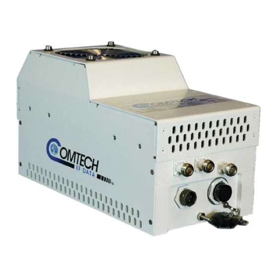
Comtech EF Data’s LPOD C-/Ku-Band Outdoor Amplifier/Block Up Converter (BUC) – referred to throughout this manual as the LPOD – delivers its rated power, guaranteed, to the transmit waveguide flange at the 1 dB compression point. It provides a cost effective, more reliable replacement for Traveling Wave Tube (TWT) amplifiers in satellite communications. -
Page 40: Functional Description
1.3.3 Built-in Redundancy Controller The LPOD has the ability to function as a 1:1 (one backup for one primary) redundant controller in a redundant mode without the use of an external device. The optional redundancy configuration is implemented by attaching a ganged waveguide/coax transfer switch(es) to the input and output connectors of the amplifiers, using a combination coaxial cable and waveguide kit. -
Page 41: Smart Buc" Functionality
1.3.7 Optional LNB Support The LPOD was designed with the evolution of L-band systems in mind. No longer relegated to low power single carrier installations, L-band IF topologies are now found in larger multi-carrier installations. A challenge presented by multi-carrier L-band systems is the presence of DC and reference components on the Tx/Rx L-band interfaces. -
Page 42: Theory Of Operation
Introduction MN-LPOD Theory of Operation 1.4.1 SSPA Block Diagrams Block diagrams for the LPOD PS-1 and PS-2 SSPAs are shown in Figure 1-2 and Figure 1-3. The major components of an LPOD unit are: • SSPA Module • Cooling System •... -
Page 43: Sspa Module
LPOD C-/Ku-Band Outdoor Amplifier / Block Up Converter (BUC) Revision 3 Introduction MN-LPOD Figure 1-3. LPOD PS-2 Block Diagram 1.4.2 SSPA Module The amplifier module performs the core function of the unit. An isolator is at the RF input to ensure good voltage standing wave ratio (VSWR). -
Page 44: Cooling System
1.4.3 Cooling System The LPOD contains a robust heat sink and thermal design to maintain a low operating temperature. The LPOD PS-1 contains one temperature-controlled fan, and the LPOD PS-2 contains two temperature-controlled fans that are monitored by the M&C board. The fans draw cool outside air in across the power supply and specialized heat sink. -
Page 45: Block Up Converter (Buc) Input
Unlike most BUCs, no DC bias voltage should be provided on the center conductor of the L-Band coax. In addition, the LPOD is available with an internal 10 MHz reference. As, such, no 10 MHz reference is required on the center conductor of the L-Band coax. If a reference is provided on the coax, the internal reference will detect and lock to it. -
Page 46: Summary Of Specifications
LPOD C-/Ku-Band Outdoor Amplifier / Block Up Converter (BUC) Revision 3 Introduction MN-LPOD Summary of Specifications 1.5.1 Characteristics Note 1 IF Input Frequency RF Output Frequency 950 – 1525 MHz 5.850 – 6.425 GHz 950 – 1750 MHz 5.850 – 6.650 GHz (optional) 950 –... -
Page 47: Optional Internal Reference
LPOD C-/Ku-Band Outdoor Amplifier / Block Up Converter (BUC) Revision 3 Introduction MN-LPOD 2° typ., 3.5° max. @ Rated P1dB output power AM/PM Conversion Third-order Intermodulation Level (2 tones, @ -3 dB Total Backoff from P1 dB -30 dBc typ., -25 dBc Guaranteed (-6 dBc SCL), Δ... -
Page 48: Environmental
LPOD C-/Ku-Band Outdoor Amplifier / Block Up Converter (BUC) Revision 3 Introduction MN-LPOD 1.5.4 Environmental -40º to 122ºF (-40º to 55ºC) Standard Operating -40º to 140ºF (-40º to 60ºC) Temperature Optional -67º to 167ºF (-55º to 75ºC) Storage 100% condensing rain 2” per hour... -
Page 49: Dimensional Envelopes
LPOD C-/Ku-Band Outdoor Amplifier / Block Up Converter (BUC) Revision 3 Introduction MN-LPOD Dimensional Envelopes Figure 1-4. LPOD Ku-Band PS-1 Dimensional Envelope (Waveguide Output) 1–11... -
Page 50: Figure 1-5. Lpod C-Band Ps-1 Dimensional Envelope (Coax Output)
LPOD C-/Ku-Band Outdoor Amplifier / Block Up Converter (BUC) Revision 3 Introduction MN-LPOD Figure 1-5. LPOD C-Band PS-1 Dimensional Envelope (Coax Output) 1–12... -
Page 51: Figure 1-6. Lpod Ps-2 Dimensional Envelope
LPOD C-/Ku-Band Outdoor Amplifier / Block Up Converter (BUC) Revision 3 Introduction MN-LPOD Figure 1-6. LPOD PS-2 Dimensional Envelope 1–13... - Page 52 LPOD C-/Ku-Band Outdoor Amplifier / Block Up Converter (BUC) Revision 3 Introduction MN-LPOD Notes: 1–14...
-
Page 53: Figure 2-1. Lpod Connectors
This chapter summarizes the connectors provided for all necessary external connections between the LPOD PS-1 (Figure 2-1 TOP) or PS-2 (Figure 2-1 BOTTOM) units and other equipment. Basic installation and operational information is also provided in Sect.2.3. For a detailed overview on the LPOD’s operability (via remote M&C commands/queries), refer to Appendix B. -
Page 54: Chapter 2. System Connections, Installation And Operation
WARNING The J2 RF Out connector may be a waveguide or coaxial interface, as shown in Figure 2-1. The type of interface used depends on the LPOD model and/or frequency range of the unit, as described in Table 2-1. Table 2-1. J2 RF Output... -
Page 55: 2.2.3 Connector J3 - Ac Power Mains
PS-2 model power connections are not the same. Product damage or personal injury may result from not properly reviewing the information in this WARNING section. For both the LPOD PS-1 and LPOD PS-2 models, the prime power input requirements are as follows: • 90-264 VAC •... -
Page 56: 2.2.4 Connector J3 - Dc Power Mains
WARNING section. For both the LPOD PS-1 and LPOD PS-2 models, the prime power input requirements are 38-72 VDC. The total power required from the prime power supply depends on the model used. Please refer to Sect. 1.5 Summary of Specifications. -
Page 57: Lpod Ps-2 J3 48Vdc Power Main Option
2.2.4.3 LPOD PS-2 J3 48VDC Power Main Option The connector type and mating connector specification unique to the LPOD PS-2 48 VDC power interface option, and the pin assignments (Table 2-6) are as follows: Unit Connector Type: CEFD P/N CN-0000288 (ITT Cannon CA3102E20-15SB-F80A232). -
Page 58: Connector J6 - Com1 (Remote Communications And Discrete Control Port)
LPOD C-/Ku-Band Outdoor Amplifier/Block Up Converter Revision 3 System Connections, Installation, and Operation MN-LPOD 2.2.5 Connector J6 – COM1 (Remote Communications and Discrete Control Port) The COM 1/ Discrete Control connector J6 is the primary input for controlling and monitoring the SSPA. -
Page 59: Connector J9 - Output Sample (Ps-2 Only)
LPOD C-/Ku-Band Outdoor Amplifier/Block Up Converter Revision 3 System Connections, Installation, and Operation MN-LPOD 2.2.6 Connector J9 – Output Sample (PS-2 Only) The Output Sample port connector is a Type ‘N’ female connector available only on the PS-2 model. It provides a nominal -40 dB sample of the output signal. -
Page 60: Standalone Installation Of The Lpod
WARNING The LPOD does not contain a ‘Power On/Off’ switch. The SSPA is powered ON by connecting the J3 AC Power connector to the appropriate prime power source. The Mute or Transmit status of the SSPA will automatically come up in the last stored state (factory default = Transmit on, not muted). -
Page 61: Figure 2-3. Universal Pole Mounting Kit, Pl/12319-1
LPOD C-/Ku-Band Outdoor Amplifier/Block Up Converter Revision 3 System Connections, Installation, and Operation MN-LPOD PL/12319-1 Universal Pole Mounting Kit ITEM CEFD PART NO. DESCRIPTION BRACKET, UNISTRUT (SHOWN CLARITY ONLY, INCLUDED IN CEFD P/N FP/BR0078 BRACKET MODIFICATION POLE MOUNTING KIT) FP/BR0072... -
Page 62: Figure 2-4. Lpod Ps-1 Single Unit Mounting Kit, Kt-0000095
BRACKET MODIFICATION POLE MOUNTING KIT HW/1/4-20X1/2FH SCREW, 1/4-20 X 1/2 FH PHIL, 82, UCUT, SS HW-0000070 SCREW, HEX, FLG, 0.375-16 X 0.750, SST, SERR HW/3/8SPRINGNUT SPRINGNUT, 3/8-16, SHORT SPRING, SST (P3300) Figure 2-4. LPOD PS-1 Single Unit Mounting Kit, KT-0000095 2–10... -
Page 63: Figure 2-5. Lpod Ps-2 Single Unit Mounting Kit, Kt-0000125
SCREW, HEX, FLG, 0.375-16 X 0.750, S.S., SERR HW/3/8SPRINGNUT SPRINGNUT, 3/8-16, SHORT SPRING, S.S. (P3300) HW/5/16-18X3/4B 5/16-18 X 3/4 HEX HEAD BOLT, S.S. HW/5/16-SPLIT 5/16 SPLIT LOCK WASHER HW/5/16-FLT FLAT WASHER, 5/16 Figure 2-5. LPOD PS-2 Single Unit Mounting Kit, KT-0000125 2–11... - Page 64 LPOD C-/Ku-Band Outdoor Amplifier/Block Up Converter Revision 3 System Connections, Installation, and Operation MN-LPOD Notes: 2–12...
-
Page 65: Chapter 3. Flash Upgrading
Chapter 3. FLASH UPGRADING Introduction The LPOD PS-1 and PS-2 (collectively referred to hereafter as ‘the LPOD’) use ‘Flash memory’ technology, and new firmware can be uploaded to either unit from an external ® Microsoft Windows -compatible computer. This makes... -
Page 66: Ethernet Ftp Upload Procedure
LPOD C-/Ku-Band Outdoor Amplifier / Block Up Converter (BUC) Revision 3 Flash Upgrading MN-LPOD Ethernet FTP Upload Procedure Step Procedure Identify the reflashable product, firmware number, and version for download. Using serial remote control, the firmware revision levels can be obtained with the following remote queries: Abbreviated: <0/SWR? which returns basic Boot, Bulk1 and Bulk2 information. -
Page 67: Home | Home .............................................................................................................. 4–9
The default parameters for all boxes are generally acceptable. Connect the PC to the LPOD’s J6 / COM1 port using the appropriate adapter cable. Send a “ping” command to the LPOD to verify the connection and communication. The IP address of the LPOD can be found remotely using the <0/IPA? query. - Page 68 (or Desktop), or by selecting the application from the Program Files menu: a) Type in the correct IP address of the LPOD. b) Select the firmware bulk image file as identified in Step 3. Type in the name, or select the file using [Browse].
-
Page 69: Chapter 4. Lpod Ethernet Management
MANAGEMENT Overview The sections that follow describe the functionality of the LPOD Ethernet (HTTP) Interface. Please refer to the Remote Commands Specifications tables found in Appendix B. REMOTE CONTROL for detailed descriptions of the configuration parameters featured on the individual Web pages depicted in this section. -
Page 70: 4.3.1 Management Information Base (Mib) Files
“SNMPv1” traps are to be used. 4.3.2 SNMP Community Strings The LPOD uses community strings as a password scheme that provides authentication before gaining access to the LPOD agent’s MIBs. In “SNMP v1/v2c”, the community string is sent unencrypted in the SNMP packets. Caution must be taken by the network administrator to ensure that SNMP packets travel only over a secure and private network if security is a concern. -
Page 71: 4.3.3 Snmp Traps
The LPOD has the ability to send out SNMP traps when certain events occur in the unit. The LPOD sends out traps when a fault occurs in the unit. A trap is sent both when a fault occurs and is cleared. - Page 72 LPOD C-/Ku-Band Outdoor Amplifier/Block Up Converter Revision 3 Ethernet Management MN-LPOD lpodBUCLockDetectStatusV1 62474821 lpodRefLockDetectStatusV1 62474822 lpodLNBCSStatusV1 62474823 lpodSwitchStatusV1 62474824 Faults SNMPv2 notifications: lpodPowerSupply24V1Status 1.3.6.1.4.1.6247.48.1.3.1.1 lpodPowerSupply24V2Status 1.3.6.1.4.1.6247.48.1.3.1.2 lpodPowerSupplyLNBStatus 1.3.6.1.4.1.6247.48.1.3.1.3 lpodPowerSupply13VStatus 1.3.6.1.4.1.6247.48.1.3.1.4 lpodPowerSupply10VStatus 1.3.6.1.4.1.6247.48.1.3.1.5 lpodRFPowerSupply10V1Status 1.3.6.1.4.1.6247.48.1.3.1.6 lpodRFPowerSupply10V2Status 1.3.6.1.4.1.6247.48.1.3.1.7 lpodPowerSupply7V8TStatus 1.3.6.1.4.1.6247.48.1.3.1.8 lpodPowerSupply5V8TStatus 1.3.6.1.4.1.6247.48.1.3.1.9 lpodPowerSupply2V5TStatus 1.3.6.1.4.1.6247.48.1.3.1.10...
-
Page 73: Telnet Interface
Ethernet Management MN-LPOD Telnet Interface The LPOD provides a Telnet interface for the purpose of Equipment M&C via the standard equipment Remote Control protocol. The Telnet interface requires user login at the Administrator level and Read/Write level. The screen capture below shows the login process: Once logged into the Telnet interface as the Administrator, the user can access the standard remote control interface defined in Appendix B. -
Page 74: Web Server (Http) Interface
The embedded Web Server application provides the user with an easy to use interface to configure and monitor all aspects of the LPOD. These Web pages have been designed for optimal performance when using Microsoft’s Internet Explorer Version 5.5 or higher (the examples shown use Internet Explorer Version 6.0). -
Page 75: 4.5.3 Web Server Interface Access
See Appendix B. REMOTE CONTROL for more information on the LRS and IPA commands. 4.5.3 Web Server Interface Access 1. From the PC, type http://192.168.1.4 (the default IP address for the LPOD) into the Address area of the Web browser:... -
Page 76: 4.5.4 Web Server Interface "Splash" Page
Once the valid IP address and login information has been entered, the LPOD Server Interface “Splash” page is displayed: The options available through the LPOD Web Server Interface are illustrated via the following menu tree: Home Admin Config Status Home... -
Page 77: Web Server
4.5.5.1.1 Home | Home Figure 4-1. LPOD Home | Home page Select the Contact or Support hyperlinks from this top-level page. From any location within the Base Modulator Web Server Interface, the user can select the Home tab and/or hyperlink to return back to this page. -
Page 78: Home | Contact
LPOD C-/Ku-Band Outdoor Amplifier/Block Up Converter Revision 3 Ethernet Management MN-LPOD 4.5.5.1.2 Home | Contact Figure 4-2. Home | Contact page The ‘Home | Contact’ page (Figure 4-2) provides basic contact information to reach Comtech EF Data Sales and Customer Support via phone or automated e-mail links. -
Page 79: Home | Support
Fill in the appropriate user information as required under Contact Information; the Problem Report text window allows up to 256 characters maximum. The LPOD Support Web Page uses SMTP (Simple Mail Transport Protocol) to send e-mail to Comtech EF Data Modulator Support (cdmipsupport@comtechefdata.com). -
Page 80: Admin
Figure 4-4. Admin | Access page The ‘Admin | Access’ page (Figure 4-4) provides the means to set up and maintain user names, passwords, the e-mail server, and the host IP addresses to facilitate communication with the LPOD Web Server. - Page 81 System Account Access Information, the user should instead click [Reset]. Webpage Timeout Using the drop-down menu, select the desired time lapse before the LPOD Web Server Interface pages time out – the user may choose either five minutes or eight hours. The default timeout setting is five minutes.
-
Page 82: Admin | Snmp
Admin | SNMP Figure 4-5. Admin | SNMP page The ‘Admin | SNMP’ page (Figure 4-5) sets and returns administration information for the LPOD Simple Network Management Protocol (SNMP) feature. Simple Network Management Operational Status: Using the drop-down menu, select the Simple Network Management operational setting as Enabled or Disabled. -
Page 83: Config
LPOD C-/Ku-Band Outdoor Amplifier/Block Up Converter Revision 3 Ethernet Management MN-LPOD 4.5.5.3 Config Pages 4.5.5.3.1 Config | Amplifier Figure 4-6. Config | Amplifier page The ‘Config | Amplifier’ page (Figure 4-6) provides the means to configure the communications , operations, and alarms/faults handling for the amplifier. - Page 84 LPOD C-/Ku-Band Outdoor Amplifier/Block Up Converter Revision 3 Ethernet Management MN-LPOD • AUX Mute: Using the drop-down menu, select the Auxiliary Mute Mode as either Enabled or Disabled. • Attenuation Offset: Enter a valid value, in dB, for the attenuation offset.
-
Page 85: Config | Lnb
LPOD C-/Ku-Band Outdoor Amplifier/Block Up Converter Revision 3 Ethernet Management MN-LPOD 4.5.5.3.2 Config | LNB Figure 4-7. Config | LNB page The ‘Config | LNB’ page (Figure 4-7) is used to configure Low-Noise Block Downconverter parameters, and display the LNB status for L-Band operation. -
Page 86: Config | Utility
4.5.5.3.3 Config | Utility Figure 4-8. Config | Utility page The ‘Config | Utility’ page (Figure 4-8) is used to configure LPOD operating parameters. Date and Time • The user may enter a date using international format in the form DD/MM/YY (where DD = day [01 to 31], MM = month [01 to 12], and YY = year [00 to 99]). - Page 87 Using the drop-down menu, select Reboot Image 1 or 2. Press [Submit] when done. Perform Soft Reboot Click [Reboot Now] to reboot the LPOD using the Current Active Firmware Image. Firmware Information (read-only) Provides the user with a read-only scrollable window to view information about the currently loaded Bootrom;...
-
Page 88: Config | Redundancy
For detailed information about 1:1 Redundant operations, see Appendix A. 1:1 REDUNDANCY. IMPORTANT Figure 4-9. Config | Redundancy page The ‘Config | Redundancy’ page (Figure 4-9) is used to configure the LPOD’s Redundancy Switch Mode. Using the drop-down menu, select the Switch Mode as follows: •... -
Page 89: Status
Figure 4-10. Status | Events page The ‘Status | Events’ page (Figure 4-10) provides the user with all pertinent information about stored events, and provides the user with a means to define the LPOD alarm parameters which determine how those events are triggered. - Page 90 LPOD C-/Ku-Band Outdoor Amplifier/Block Up Converter Revision 3 Ethernet Management MN-LPOD Alarm Mask Using the drop-down menus, select each alarm as either Fault, Alarm or Masked for: • Low Forward RF Power • Fan Speed • LNB 22V Power Supply •...
-
Page 91: Status | Statistics
Figure 4-11. Status | Statistics page The ‘Status | Statistics’ page (Figure 4-11) provides the user with all unread (stored) statistics, and provides the means to configure how statistics are handled and displayed by the LPOD. Unread Storage Statistics: ### This read-only scrollable window displays the unread stored statistics log in sequential, date- stamped format. -
Page 92: Status | Status
LPOD C-/Ku-Band Outdoor Amplifier/Block Up Converter Revision 3 Ethernet Management MN-LPOD • Statistics Averaging: Using the drop-down menu, select either Enable or Disable to set the Statistics Averaging function When Enabled, statistics data is averaged at a rate of once per second for 10 seconds. If Disabled, burst values will be logged instead of averaged values. -
Page 93: Status | Fets
LPOD C-/Ku-Band Outdoor Amplifier/Block Up Converter Revision 3 Ethernet Management MN-LPOD 4.5.5.4.4 Status | FETs Figure 4-13. Status | FETs page The ‘Status| FETs’ page (Figure 4-13) features a read-only scrollable window that displays the operating currents of all FETs (Field Effect Transistors) installed in the RF amplifier. - Page 94 LPOD C-/Ku-Band Outdoor Amplifier/Block Up Converter Revision 3 Ethernet Management MN-LPOD Notes: 4–26...
-
Page 95: Appendix A. 1:1 Redundancy
The LPOD redundant mode does not specify which unit must be the backup (offline) unit. Instead, the status of the backup (offline) and active (online) units are determined by the waveguide switch position. - Page 96 LPOD C-/Ku-Band Outdoor Amplifier/ Block Up Converter (BUC) Revision 3 Appendix A MN-LPOD Redundant mode allows the backup (offline) unit to take control of the redundant system and force a redundant switchover when there is a problem with the active (online) unit. Currently, 1:1 redundancy is supported with either transmit switching or transmit and receive switching.
-
Page 97: Applicable Redundancy Commands
Appendix B. REMOTE CONTROL Redundancy System Assembly Kits Several kits are available from Comtech EF Data to mount and install standalone or redundant LPODs, depending on the type of unit ordered and its operational frequency. Refer to Chapter 2. SYSTEM CONNECTIONS, INSTALLATION AND OPERATION for the available assembly kit options for 1:1 LPOD standalone configurations. -
Page 98: Table A-1. Kt-0000116 Lpod Rx Splitter / Cable Kit Bom
A-1, A-2 KT-0000098 KIT, Rx SWITCH, LPOD Ku-BAND A-3, A-4 PL/7596-1 KIT, MTG & CABLE, Tx SWITCH, C-BAND, WAVEGUIDE OUTPUT, 1:1, LPOD PS-1 A-5, A-6 KT-0000104 KIT, MTG & CABLE, Tx SWITCH, C-BAND, COAX OUTPUT, 1:1, LPOD PS-1 A-7, A-8 KT-0000090 KIT, MTG &... -
Page 99: Figure A-1. Kt-0000098 Lpod C-Band Rx Switch Kit (Assembled View
LPOD C-/Ku-Band Outdoor Amplifier/ Block Up Converter (BUC) Revision 3 Appendix A MN-LPOD Figure A-1. KT-0000098 LPOD C-Band Rx Switch Kit (Assembled View) A–5... -
Page 100: Figure A-2. Kt-0000098 Lpod C-Band Rx Switch Kit (Exploded View
LPOD C-/Ku-Band Outdoor Amplifier/ Block Up Converter (BUC) Revision 3 Appendix A MN-LPOD Figure A-2. KT-0000098 LPOD C-Band Rx Switch Kit (Exploded View) A–6... -
Page 101: Figure A-3. Pl/7596-1 Lpod Ku-Band Rx Switch Kit (Assembled View
LPOD C-/Ku-Band Outdoor Amplifier/ Block Up Converter (BUC) Revision 3 Appendix A MN-LPOD Figure A-3. PL/7596-1 LPOD Ku-Band Rx Switch Kit (Assembled View) A–7... -
Page 102: Figure A-4. Pl/7596-1 Lpod Ku-Band Rx Switch Kit (Exploded View
LPOD C-/Ku-Band Outdoor Amplifier/ Block Up Converter (BUC) Revision 3 Appendix A MN-LPOD Figure A-4. PL/7596-1 LPOD Ku-Band Rx Switch Kit (Exploded View) A–8... -
Page 103: Figure A-5. Kt-0000104 Lpod Ps-1 C-Band (Waveguide) 1:1 Redundancy Kit (Assembled View
LPOD C-/Ku-Band Outdoor Amplifier/ Block Up Converter (BUC) Revision 3 Appendix A MN-LPOD Figure A-5. KT-0000104 LPOD PS-1 C-Band (Waveguide) 1:1 Redundancy Kit (Assembled View) A–9... -
Page 104: Table A-4. Kt-0000104 Lpod Ps-1 1:1 Redundancy Kit Bom
LPOD C-/Ku-Band Outdoor Amplifier/ Block Up Converter (BUC) Revision 3 Appendix A MN-LPOD Table A-4. KT-0000104 LPOD PS-1 1:1 Redundancy Kit BOM KT-0000104 LPOD PS-1 C-Band (Waveguide) 1:1 Redundancy Kit (as per Figure A-2) ITEM CEFD PART NO. DESCRIPTION FP-0000534... -
Page 105: Figure A-6. Kt-0000104 Lpod Ps-1 C-Band (Waveguide) 1:1 Redundancy Kit (Exploded View
LPOD C-/Ku-Band Outdoor Amplifier/ Block Up Converter (BUC) Revision 3 Appendix A MN-LPOD Figure A-6. KT-0000104 LPOD PS-1 C-Band (Waveguide) 1:1 Redundancy Kit (Exploded View) A–11... - Page 106 LPOD C-/Ku-Band Outdoor Amplifier/ Block Up Converter (BUC) Revision 3 Appendix A MN-LPOD This page is intentionally blank. A–12...
-
Page 107: Figure A-7. Kt-0000090 Lpod Ps-1 C-Band (Coax) 1:1 Redundancy Kit (Assembled View
LPOD C-/Ku-Band Outdoor Amplifier/ Block Up Converter (BUC) Revision 3 Appendix A MN-LPOD Figure A-7. KT-0000090 LPOD PS-1 C-Band (Coax) 1:1 Redundancy Kit (Assembled View) A–13... -
Page 108: Table A-5. Kt-0000090 Lpod Ps-1 C-Band (Coax) 1:1 Redundancy Kit Bom
LPOD C-/Ku-Band Outdoor Amplifier/ Block Up Converter (BUC) Revision 3 Appendix A MN-LPOD Table A-5. KT-0000090 LPOD PS-1 C-Band (Coax) 1:1 Redundancy Kit BOM KT-0000090 LPOD PS-1 C-Band (Coax) 1:1 Redundancy Kit (as per Figure A-4) ITEM CEFD PART NO. DESCRIPTION FP-0000534... -
Page 109: Figure A-8. Kt-0000090 Lpod Ps-1 C-Band (Coax) 1:1 Redundancy Kit (Exploded View
LPOD C-/Ku-Band Outdoor Amplifier/ Block Up Converter (BUC) Revision 3 Appendix A MN-LPOD Figure A-8. KT-0000090 LPOD PS-1 C-Band (Coax) 1:1 Redundancy Kit (Exploded View) A–15... - Page 110 LPOD C-/Ku-Band Outdoor Amplifier/ Block Up Converter (BUC) Revision 3 Appendix A MN-LPOD This page is intentionally blank. A–16...
-
Page 111: Figure A-9. Kt-0000089 Lpod Ps-1 Ku-Band 1:1 Redundancy Kit (Assembled View
LPOD C-/Ku-Band Outdoor Amplifier/ Block Up Converter (BUC) Revision 3 Appendix A MN-LPOD Figure A-9. KT-0000089 LPOD PS-1 Ku-Band 1:1 Redundancy Kit (Assembled View) A–17... -
Page 112: Table A-6. Kt-0000089 Lpod Ps-1 Ku-Band 1:1 Redundancy Kit Bom
LPOD C-/Ku-Band Outdoor Amplifier/ Block Up Converter (BUC) Revision 3 Appendix A MN-LPOD Table A-6. KT-0000089 LPOD PS-1 Ku-Band 1:1 Redundancy Kit BOM KT-0000089 LPOD PS-1 Ku-Band 1:1 Redundancy Kit (as per Figure A-6) ITEM CEFD PART NO. DESCRIPTION FP-0000534... -
Page 113: Figure A-10. Kt-0000089 Lpod Ps-1 Ku-Band 1:1 Redundancy Kit (Exploded View
LPOD C-/Ku-Band Outdoor Amplifier/ Block Up Converter (BUC) Revision 3 Appendix A MN-LPOD Figure A-10. KT-0000089 LPOD PS-1 Ku-Band 1:1 Redundancy Kit (Exploded View) A–19... - Page 114 LPOD C-/Ku-Band Outdoor Amplifier/ Block Up Converter (BUC) Revision 3 Appendix A MN-LPOD This page is intentionally blank. A–20...
-
Page 115: Figure A-11. Kt-0000091 Lpod Ps-2 C-Band 1:1 Redundancy Kit (Assembled View
LPOD C-/Ku-Band Outdoor Amplifier/ Block Up Converter (BUC) Revision 3 Appendix A MN-LPOD Figure A-11. KT-0000091 LPOD PS-2 C-Band 1:1 Redundancy Kit (Assembled View) A–21... -
Page 116: Table A-7. Kt-0000091 Lpod Ps-2 C-Band 1:1 Redundancy Kit Bom
LPOD C-/Ku-Band Outdoor Amplifier/ Block Up Converter (BUC) Revision 3 Appendix A MN-LPOD Table A-7. KT-0000091 LPOD PS-2 C-Band 1:1 Redundancy Kit BOM KT-0000091 LPOD PS-2 C-Band 1:1 Redundancy Kit (as per Figure A-8) ITEM CEFD PART NO. DESCRIPTION FP-0000552... -
Page 117: Figure A-12. Kt-0000091 Lpod Ps-2 C-Band 1:1 Redundancy Kit (Exploded View
LPOD C-/Ku-Band Outdoor Amplifier/ Block Up Converter (BUC) Revision 3 Appendix A MN-LPOD Figure A-12. KT-0000091 LPOD PS-2 C-Band 1:1 Redundancy Kit (Exploded View) A–23... - Page 118 LPOD C-/Ku-Band Outdoor Amplifier/ Block Up Converter (BUC) Revision 3 Appendix A MN-LPOD Notes: A–24...
-
Page 119: Appendix B. Remote Control
The LPOD may be muted via software or discrete control. Exercising the command will MUT=1 “software” mute the unit. The LPOD also may be “hardware” muted by pulling Pin ‘S’ on the J6 (COM1) Discrete control connector to ground (See Chapter 2. SYSTEM CONNECTIONS, INSTALLATION OPERATION). -
Page 120: B.1.5 Power Detector
Appendix B MN-LPOD B.1.4 Faults The M&C system monitors certain key functions of the LPOD for proper operation. Should any of these parameters exceed predetermined limits, the M&C system will declare a fault. The conditions that trigger a fault are: •... -
Page 121: Remote Control Protocol And Structure
LPOD C- / Ku-Band Outdoor Amplifier/ Block Up Converter (BUC) Revision 3 Appendix B MN-LPOD Remote Control Protocol and Structure This section describes the protocol and message command set for remote monitor and control of the LPOD. The electrical interface is either an RS-485 multi-drop bus (for the control of many devices) or an RS-232 connection (for the control of a single device), and data is transmitted in asynchronous serial form, using ASCII characters. -
Page 122: B.2.4 Packet Structure
LPOD C- / Ku-Band Outdoor Amplifier/ Block Up Converter (BUC) Revision 3 Appendix B MN-LPOD B.2.3 Basic Protocol Whether in RS-232 or RS-485 mode, all data is transmitted as asynchronous serial characters, suitable for transmission and reception by a UART. The character format should be 8N1 (8 data bits, no parity, 1 stop bit). -
Page 123: B.2.4.2 Target Address
LPOD C- / Ku-Band Outdoor Amplifier/ Block Up Converter (BUC) Revision 3 Appendix B MN-LPOD B.2.4.2 Target Address Up to 9,999 devices can be uniquely addressed. In RS-232 applications this value is set to 0. In RS-485 applications, the permissible range of values is 1 to 9999. -
Page 124: B.2.4.5 Instruction Code Qualifier
LPOD C- / Ku-Band Outdoor Amplifier/ Block Up Converter (BUC) Revision 3 Appendix B MN-LPOD B.2.4.5 Instruction Code Qualifier This single character further qualifies the preceding instruction code. Code Qualifiers obey the following rules: 1. From Controller-to-Target, the only permitted values are:... - Page 125 LPOD C- / Ku-Band Outdoor Amplifier/ Block Up Converter (BUC) Revision 3 Appendix B MN-LPOD B.2.4.6 Optional Message Arguments Arguments are not required for all messages. Arguments are ASCII codes for any printable character. B.2.4.7 End of Packet Controller-to-Target: This is the 'Carriage Return' character (ASCII code 13).
-
Page 126: Remote Commands And Queries
LPOD C- / Ku-Band Outdoor Amplifier/ Block Up Converter (BUC) Revision 3 Appendix B MN-LPOD Remote Commands and Queries Column ‘C’ = Command; Column ‘Q’ = Query; columns marked ‘X’ designate instruction code as Command only, Query only, or Command/Query. - Page 127 LPOD C- / Ku-Band Outdoor Amplifier/ Block Up Converter (BUC) Revision 3 Appendix B MN-LPOD Note: Where Parameter Type is in the format <description> , while the underlying command will remain, the specific functionality will be obsolete and should not be used for new implementations. There generally will be a different command elsewhere that encapsulates the marked functionality.
- Page 128 LPOD C- / Ku-Band Outdoor Amplifier/ Block Up Converter (BUC) Revision 3 Appendix B MN-LPOD Command Arguments for Query Response to Description of Arguments Response to (Instruction Command or (Instruction Query Parameter Type (Note that all arguments are printable ASCII...
- Page 129 LPOD C- / Ku-Band Outdoor Amplifier/ Block Up Converter (BUC) Revision 3 Appendix B MN-LPOD Command Arguments for Query Response to Description of Arguments Response to (Instruction Command or (Instruction Query Parameter Type (Note that all arguments are printable ASCII...
- Page 130 LPOD C- / Ku-Band Outdoor Amplifier/ Block Up Converter (BUC) Revision 3 Appendix B MN-LPOD Command Arguments for Query Response to Description of Arguments Response to (Instruction Command or (Instruction Query Parameter Type (Note that all arguments are printable ASCII...
- Page 131 LPOD C- / Ku-Band Outdoor Amplifier/ Block Up Converter (BUC) Revision 3 Appendix B MN-LPOD Command Arguments for Query Response to Description of Arguments Response to (Instruction Command or (Instruction Query Parameter Type (Note that all arguments are printable ASCII...
- Page 132 LPOD C- / Ku-Band Outdoor Amplifier/ Block Up Converter (BUC) Revision 3 Appendix B MN-LPOD Command Arguments for Query Response to Description of Arguments Response to (Instruction Command or (Instruction Query Parameter Type (Note that all arguments are printable ASCII...
- Page 133 LPOD C- / Ku-Band Outdoor Amplifier/ Block Up Converter (BUC) Revision 3 Appendix B MN-LPOD Command Arguments for Query Response to Description of Arguments Response to (Instruction Command or (Instruction Query Parameter Type (Note that all arguments are printable ASCII...
- Page 134 LPOD C- / Ku-Band Outdoor Amplifier/ Block Up Converter (BUC) Revision 3 Appendix B MN-LPOD Command Arguments for Query Response to Description of Arguments Response to (Instruction Command or (Instruction Query Parameter Type (Note that all arguments are printable ASCII...
- Page 135 LPOD C- / Ku-Band Outdoor Amplifier/ Block Up Converter (BUC) Revision 3 Appendix B MN-LPOD Command Arguments for Query Response to Description of Arguments Response to (Instruction Command or (Instruction Query Parameter Type (Note that all arguments are printable ASCII...
- Page 136 LPOD C- / Ku-Band Outdoor Amplifier/ Block Up Converter (BUC) Revision 3 Appendix B MN-LPOD Command Arguments for Query Response to Description of Arguments Response to (Instruction Command or (Instruction Query Parameter Type (Note that all arguments are printable ASCII...
- Page 137 LPOD C- / Ku-Band Outdoor Amplifier/ Block Up Converter (BUC) Revision 3 Appendix B MN-LPOD Command Arguments for Query Response to Description of Arguments Response to (Instruction Command or (Instruction Query Parameter Type (Note that all arguments are printable ASCII...
- Page 138 LPOD C- / Ku-Band Outdoor Amplifier/ Block Up Converter (BUC) Revision 3 Appendix B MN-LPOD Command Arguments for Query Response to Description of Arguments Response to (Instruction Command or (Instruction Query Parameter Type (Note that all arguments are printable ASCII...
- Page 139 LPOD C- / Ku-Band Outdoor Amplifier/ Block Up Converter (BUC) Revision 3 Appendix B MN-LPOD Command Arguments for Query Response to Description of Arguments Response to (Instruction Command or (Instruction Query Parameter Type (Note that all arguments are printable ASCII...
- Page 140 LPOD C- / Ku-Band Outdoor Amplifier/ Block Up Converter (BUC) Revision 3 Appendix B MN-LPOD Command Arguments for Query Response to Description of Arguments Response to (Instruction Command or (Instruction Query Parameter Type (Note that all arguments are printable ASCII...
- Page 141 LPOD C- / Ku-Band Outdoor Amplifier/ Block Up Converter (BUC) Revision 3 Appendix B MN-LPOD Command Arguments for Query Response to Description of Arguments Response to (Instruction Command or (Instruction Query Parameter Type (Note that all arguments are printable ASCII...
- Page 142 LPOD C- / Ku-Band Outdoor Amplifier/ Block Up Converter (BUC) Revision 3 Appendix B MN-LPOD Command Arguments for Query Response to Description of Arguments Response to (Instruction Command or (Instruction Query Parameter Type (Note that all arguments are printable ASCII...
- Page 143 LPOD C- / Ku-Band Outdoor Amplifier/ Block Up Converter (BUC) Revision 3 Appendix B MN-LPOD Command Arguments for Query Response to Description of Arguments Response to (Instruction Command or (Instruction Query Parameter Type (Note that all arguments are printable ASCII...
- Page 144 LPOD C- / Ku-Band Outdoor Amplifier/ Block Up Converter (BUC) Revision 3 Appendix B MN-LPOD Command Arguments for Query Response to Description of Arguments Response to (Instruction Command or (Instruction Query Parameter Type (Note that all arguments are printable ASCII...
- Page 145 LPOD C- / Ku-Band Outdoor Amplifier/ Block Up Converter (BUC) Revision 3 Appendix B MN-LPOD Command Arguments for Query Response to Description of Arguments Response to (Instruction Command or (Instruction Query Parameter Type (Note that all arguments are printable ASCII...
- Page 146 LPOD C- / Ku-Band Outdoor Amplifier/ Block Up Converter (BUC) Revision 3 Appendix B MN-LPOD Command Arguments for Query Response to Description of Arguments Response to (Instruction Command or (Instruction Query Parameter Type (Note that all arguments are printable ASCII...
- Page 147 LPOD C- / Ku-Band Outdoor Amplifier/ Block Up Converter (BUC) Revision 3 Appendix B MN-LPOD Command Arguments for Query Response to Description of Arguments Response to (Instruction Command or (Instruction Query Parameter Type (Note that all arguments are printable ASCII...
- Page 148 LPOD C- / Ku-Band Outdoor Amplifier/ Block Up Converter (BUC) Revision 3 Appendix B MN-LPOD Command Arguments for Query Response to Description of Arguments Response to (Instruction Command or (Instruction Query Parameter Type (Note that all arguments are printable ASCII...
- Page 149 LPOD C- / Ku-Band Outdoor Amplifier/ Block Up Converter (BUC) Revision 3 Appendix B MN-LPOD Command Arguments for Query Response to Description of Arguments Response to (Instruction Command or (Instruction Query Parameter Type (Note that all arguments are printable ASCII...
- Page 150 LPOD C- / Ku-Band Outdoor Amplifier/ Block Up Converter (BUC) Revision 3 Appendix B MN-LPOD Command Arguments for Query Response to Description of Arguments Response to (Instruction Command or (Instruction Query Parameter Type (Note that all arguments are printable ASCII...
- Page 151 METRIC CONVERSIONS Units of Length Unit Centimeter Inch Foot Yard Mile Meter Kilometer Millimeter 1 centimeter — 0.3937 0.03281 0.01094 6.214 x 10 0.01 — — 1 inch 2.540 — 0.08333 0.2778 0.254 — 25.4 1.578 x 10 1 foot 30.480 12.0 —...
- Page 152 2114 85281 WEST TH STREET TEMPE ARIZONA 480 • 333 • 2200 PHONE 480 • 333 • 2161...
Need help?
Do you have a question about the LPOD and is the answer not in the manual?
Questions and answers