Table of Contents
Advertisement
Quick Links
HPOD
C, X, Ku-Band High Power
Outdoor Amplifier
Installation and Operation Manual
Part Number MN/HPOD.IOM
Revision 9
December 19, 2022
IMPORTANT NOTE: The information contained in this document supersedes all previously published
information regarding this product. Product specifications are subject to change without prior notice.
Part Number
MN/HPOD.IOM Revision
9
Advertisement
Table of Contents

Related Manuals for Comtech EF Data HPOD


Summary of Contents for Comtech EF Data HPOD
- Page 1 HPOD C, X, Ku-Band High Power Outdoor Amplifier Installation and Operation Manual Part Number MN/HPOD.IOM Revision 9 December 19, 2022 IMPORTANT NOTE: The information contained in this document supersedes all previously published information regarding this product. Product specifications are subject to change without prior notice.
- Page 2 C-, X- and Ku-Band High-Powered Outdoor Amplifier Revision 9 Copyright © 2022 Comtech Satellite Network Technologies. All rights reserved. Printed in the USA. Comtech Satellite Network Technologies, 2114 West 7th Street, Tempe, Arizona 85281 USA, 480.333.2200, FAX: 480.333.2161 Revision History Date Description Initial Release.
-
Page 3: Table Of Contents
HPOD C-, X-, Ku-Band High-Power Outdoor Amplifier Revision 9 Table of Contents TABLE OF CONTENTS ......................I LIST OF TABLES........................V LIST OF FIGURES ........................VI PREFACE........................... I About this Manual........................i Disclaimer..........................i Conventions and References....................i Patents and Trademarks ......................i Warnings, Cautions, and Notes .................... - Page 4 2.5.1 ‘J4 | REDUNDANT LOOP’ Connector...............2–7 2.5.2 ‘J6 | COM1’ Connector .....................2–8 2.5.3 ‘J8 | INPUT SAMPLE’ Connector................2–8 2.5.4 ‘J9 | OUTPUT SAMPLE’ Connector................2–8 Energize the HPOD SSPA ..................2–9 CHAPTER 3. UPDATING FIRMWARE ................3–1 Overview ........................3–1 Getting Started: Prepare for the Firmware Download..........3–2 Download and Extract the Firmware Update ............3–5...
- Page 5 4.3.2 SNMP Community Strings ..................4–3 4.3.3 SNMP Traps......................4–3 Telnet Interface......................4–4 4.4.1 Telnet Operation via HyperTerminal .................4–5 HPOD Web Server (HTTP) Interface ................4–6 4.5.1 Enable the Web Server Interface................4–6 4.5.2 User Login ........................4–8 4.5.3 Web Server Interface – Operational Features............4–9 4.5.3.1 Navigation .........................
- Page 6 A.2.4 1:2 Unistrut Kit (Comtech P/N KT-0000017) ............A–9 A.2.5 1:1 or 1:2 Free Standing Unistrut Kit (Comtech P/N KT-0020827) ......A–11 HPOD 1:1 Redundancy System Mounting and Switch Kit Examples ....A–13 A.3.1 1:1 Redundancy System Mounting and Switch Kit Examples ........ A–13 A.3.2 Ku-Band 1:1 Free Standing Redundancy System Mounting and Switch Kit Example A–...
-
Page 7: List Of Tables
C.3.2 Install the New Fan Assembly.................. C–5 Scheduled Maintenance.................... C–6 List of Tables Table 2-1. HPOD SSPA External Connectors ..................2–3 Table 2-2. ‘J2 | RF OUT’ Waveguide Output Flange ................2–4 Table 2-3. ‘J3 | AC IN’ Connector Pinout ....................2–5 Table 2-4. -
Page 8: List Of Figures
Figure B-2. SSPA Web Server Interface – ‘Config | Redundancy’ Page..........B–5 Figure C-1. Remove/Replace the HPOD Power Supply................C–2 Figure C-2. Remove the Old HPOD Fan Assembly................. C–4 Figure C-3. Install the New HPOD Fan Assembly ................... C–5 Table of Contents TOC-vi... - Page 9 MN/HPOD.IOM Revision 9 Units of Measurement Unit / Symbol Definition Ω Ampere Alternating Current bits per second ˚C Celsius (degrees) Direct Current Hertz kiloHertz decibel Decibels relative t the carrier Decibel-milliwatts ˚F Fahrenheit (degrees) Kbps Kilobit per second kilogram ksps Kilosymbols per second lbs.
- Page 10 MN/HPOD.IOM Revision 9 BLANK PAGE Table of Contents TOC-viii MN/HPOD.IOM...
-
Page 11: Preface
This manual provides installation and operation information for the Comtech Satellite Network Technologies, Inc. (Comtech) HPOD family of High-Power Outdoor Amplifiers. This document is intended for anyone who installs or operates the HPOD C-Band, X-Band, and Ku-Band units. Disclaimer Comtech has reviewed this manual thoroughly in order to provide an easy-to-use guide to this equipment. -
Page 12: Warnings, Cautions, And Notes
HPOD C-, X-, Ku-Band High-Power Outdoor Amplifier Revision 9 Warnings, Cautions, and Notes A WARNING informs you about a possible hazard that MAY CAUSE DEATH or SERIOUS INJURY. A CAUTION informs you about a possible hazard that MAY CAUSE INJURY or PROPERTY DAMAGE. -
Page 13: Electrical Safety Notice
Grounding: The HPOD provides a grounding terminal to allow you to ground the HPOD to the antenna’s grounding network. All components installed at the antenna should be grounded to a common grounding point at the antenna. -
Page 14: Product Support
HPOD C-, X-, Ku-Band High-Power Outdoor Amplifier Revision 9 Product Support For all product support, please call: +1.240.243.1880 +1.866.472.3963 (toll free USA) Comtech Headquarters http://www.Comtechefdata.com Comtech Satellite Network Technologies, Inc. 2114 West 7th Street Tempe, Arizona USA 85281 +1.480.333.2200 Warranty Policy Comtech products are warranted against defects in material and workmanship for a specific period from the date of shipment, and this period varies by product. -
Page 15: Exclusive Remedies
HPOD C-, X-, Ku-Band High-Power Outdoor Amplifier Revision 9 The warranty does not cover damage or loss incurred in transportation of the product. The warranty does not cover replacement or repair necessitated by loss or damage from any cause beyond the control of Comtech, such as lightning or other natural and weather-related events or wartime environments. - Page 16 HPOD C-, X-, Ku-Band High-Power Outdoor Amplifier Revision 9 Notes: Preface MN/HPOD.IOM...
-
Page 17: Chapter 1. Introduction
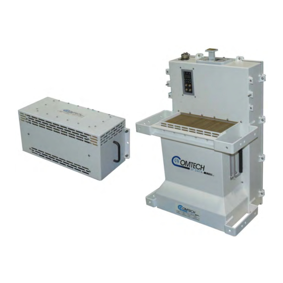
Overview Figure 1-1. Comtech HPOD SSPA Comtech’s High-Power Outdoor (HPOD) Solid-State Power Amplifier (SSPA) (Figure 1-1) delivers its rated power, guaranteed, at the 1 dB compression point, to the transmit waveguide flange. It provides a cost effective, more reliable replacement for Traveling Wave Tube Amplifiers (TWTA) in satellite communications. -
Page 18: Features
SSPA module. 1.2.3 Built-in Redundancy Controller Each HPOD has the ability to function as a 1+1 (one backup for one primary) and 1+2 (one backup for two primaries) redundancy controller in the backup mode. The optional redundancy... -
Page 19: Over Drive (Excessive Rf Input Level) And Ops
1) Overdrive protection is only available in Firmware version 1.2.1 or newer. Functional Description Each HPOD consists of a Comtech SSPA module with a field replaceable power supply, a field replaceable fan assembly, and the Monitor/Control Processor (MCP). The amplifier features a Comtech low loss combining technique and MCP based temperature versus gain compensation. -
Page 20: Dimensional Envelope
HPOD C-, X-, Ku-Band High-Power Outdoor Amplifier Revision 9 1.3.1 Dimensional Envelope Figure 1-2. HPOD SSPA Dimensional Envelope Introduction 1–4 MN/HPOD.IOM... -
Page 21: Theory Of Operation
HPOD C-, X-, Ku-Band High-Power Outdoor Amplifier Revision 9 Theory of Operation Figure 1-3 shows the block diagram for the HPOD SSPA. The major components of the unit are the: SSPA Module. Power Supply (Power Factor Corrected and Removable/Field Replaceable). -
Page 22: Sspa Module
HPOD C-, X-, Ku-Band High-Power Outdoor Amplifier Revision 9 1.4.1 SSPA Module The amplifier module performs the core function of the unit. An isolator is at the RF input to ensure good VSWR. The RF signal then passes through an input sample port and on to an electronically controlled attenuator that adjusts the overall attenuation according to the user input. -
Page 23: Block Up Converter Input Option
Unlike most BUCs, no DC bias voltage should be provided on the center conductor of the L-Band coax. In addition, the BUC version of the HPOD is available with an internal 10 MHz reference. As, such, no 10 MHz reference is required on the center conductor of the L-Band coax. If a reference is provided on the coax, the internal reference will detect and lock to it. -
Page 24: Specifications
HPOD C-, X-, Ku-Band High-Power Outdoor Amplifier Revision 9 Specifications Output C-Band X-Band Ku-Band CPR-137G Waveguide CPR-112G Waveguide WR75G Waveguide Connector 14.0 GHz -to-14.5 GHz (Standard) 5.850 GHz -to-6.425 Frequency 7.9 GHz-to-8.4 GHz 13.75 GHz -to-14.5 GHz (Optional) 200(250) 175(200) - Page 25 Optional BUC LO -20 dBm Leakage Input Impedance 50Ω Noise Figure 8 dB typical, 10 dB maximum @ maximum gain (15 dB for HPOD Ku-Band) with BUC Option 25 dB VSWR 1.25:1 Maximum with BUC Option 1.50:1 Maximum Connector Type ‘N’...
- Page 26 HPOD C-, X-, Ku-Band High-Power Outdoor Amplifier Revision 9 BLANK PAGE Introduction 1–10 MN/HPOD.IOM...
- Page 27 HPOD C-, X-, Ku-Band High-Power Outdoor Amplifier Revision 9 Notes: Introduction 1–11 MN/HPOD.IOM...
-
Page 28: Chapter 2. External Connectors And Pinouts
(Type ‘N’ shown) Figure 2-1. Coaxial Connector Example The HPOD SSPA uses Type ‘N’ coaxial cables. Type ‘N’ Coaxial cables (plugs) and their mating connectors (jacks/sockets) are available in a threaded coupling style (Figure 2-1). The jack for this coupling style features external threads. The plug shell features internal threads and has either a knurled outer surface (to permit hand tightening of the connection) or hex flats (to accommodate torqued installation). -
Page 29: Circular Cable Connections
“click” sound. HPOD SSPA Cabling Connections The HPOD SSPA external connectors (Figure 2-3) provide all necessary connections between the unit and other equipment. Table 2-1 summarizes the connectors provided here, grouped according to service function. -
Page 30: Table 2-1. Hpod Sspa External Connectors
HPOD C-, X-, Ku-Band High-Power Outdoor Amplifier Revision 9 Figure 2-3. HPOD External Connectors Table 2-1. HPOD SSPA External Connectors Connector Group Item Connector Name Connector Type Connector Function (Section) RF IN Type ‘N’ female RF Input RF Signal (Sect. 2.3) -
Page 31: Rf Signal Interface Connector Group
The ‘J1 | RF IN’ (Input) connector is a Type ‘N’ female. Typical input levels (-30 dBm) depend on desired output power and unit attenuation. To prevent damage to the HPOD SSPA, RF input levels should not exceed +15 dBm. -
Page 32: Ground And Power Connection Group
HPOD C-, X-, Ku-Band High-Power Outdoor Amplifier Revision 9 Ground and Power Connection Group 2.4.1 Ground Connection An M4 stud is provided for connecting a common chassis ground among equipment. 2.4.2 ‘J3 | AC IN’ Connector (AC Power Main) WARNING! Before applying AC power to the unit, make sure the waveguide output of the amplifier is properly loaded or terminated. -
Page 33: J10' Connector: Optional -48V Dc Power Supply
-36 to -72 VDC Careful consideration must be given to the choice of input wiring because of the current draw requirements of the HPOD. Wire that is 8 AWG or larger will be required for most installations. The total power required from the prime power supply depends on the model used. -
Page 34: Electrical Control Interface Connection Group
HPOD C-, X-, Ku-Band High-Power Outdoor Amplifier Revision 9 Electrical Control Interface Connection Group 2.5.1 ‘J4 | REDUNDANT LOOP’ Connector The ‘J4 | REDUNDANT LOOP’ connector is located near the waveguide output and is used only in configurations where the SSPA controls waveguide switching. -
Page 35: J6 | Com1' Connector
HPOD C-, X-, Ku-Band High-Power Outdoor Amplifier Revision 9 2.5.2 ‘J6 | COM1’ Connector The ‘J6 | COM1’ Discrete Control connector is the primary input for controlling and monitoring the SSPA. It is a 19-pin circular connector, type MS3112E14-19S. The pinout specification is shown in Table 2-6. -
Page 36: Energize The Hpod Sspa
‘J2 RF OUTPUT’ port. Individuals can be exposed to dangerously high electromagnetic levels. The HPOD SSPA does not contain a ‘Power On/Off’ switch. Power ON the SSPA by connecting the ‘J3 | AC IN’ Power connector to the appropriate prime power source. The Mute or Transmit status of the SSPA will automatically come up in the last stored state (factory default = Transmit on, not muted). - Page 37 HPOD C-, X-, Ku-Band High-Power Outdoor Amplifier Revision 9 Notes: External Connectors and Pinouts 2–10 MN/HPOD.IOM...
-
Page 38: Chapter 3. Updating Firmware
Windows -compatible computer. Use the appropriate adapter cable to connect the HPOD ‘J6 | COM1’ 19-pin port to a 9- pin serial port or Ethernet port of the user PC. Extract the firmware update files from the archive download file, and then transfer the files from the user PC to the HPOD via File Transfer Protocol (FTP): ... -
Page 39: Getting Started: Prepare For The Firmware Download
PC – either a 19-pin to 9-pin Serial Adapter Cable, or a 19-pin to RJ-45 Ethernet Adapter Cable. A. Connect the Adapter Cable from the HPOD ‘J6 | COM1’ port to the pertinent port on the user PC. B. On the PC – configure the terminal emulator program. - Page 40 HPOD C-, X-, Ku-Band High-Power Outdoor Amplifier Revision 9 There are several ways the user may use create a temporary folder on a Windows-based PC: A. Use the Windows Desktop to create and rename the temporary folder. Right-click anywhere on the desktop to open the popup submenu, and then select New >...
- Page 41 HPOD C-, X-, Ku-Band High-Power Outdoor Amplifier Revision 9 D. Use Windows Command-line to create the temporary folder. First, click [Start] on the Windows taskbar, and then click the ‘Run...’ icon (or, depending on Windows OS versions prior to Windows 95, click the ‘MS-DOS Prompt’...
-
Page 42: Download And Extract The Firmware Update
D. On the Flash Updates Index page – Select the (Select a Product Line) Amplifiers hyperlink. E. On the Amplifiers product page – Select the HPOD product hyperlink. F. Select the appropriate firmware archive EXE or ZIP file download hyperlink. - Page 43 *.exe or *.zip archive file with the user-supplied utility program: o Double-click on the archive file name, and then follow the prompts provided by the user-supplied utility program. For non-Ethernet HPOD downloads – extract, at a minimum, four files: o ReleaseNotes_HPOD_vXXX.pdf – Where “XXX” denotes the firmware version number.
- Page 44 HPOD C-, X-, Ku-Band High-Power Outdoor Amplifier Revision 9 B. Using Command-line: Type “cd c:\temp” at the Command-line prompt to change to the temporary directory created earlier using Command-line. Type “dir” to list the files extracted to the temporary directory from the downloaded archive file.
-
Page 45: Perform The Ftp Upload Procedures
The HPOD ‘J6 | COM1’ port is connected to the user-supplied, Windows- based PC serial port or Ethernet port, and The PC is running a terminal emulation program (for operation of the HPOD serial or Telnet interface) and/or a compatible Web Browser (for operation of the HPOD Web Server Interface). -
Page 46: Perform The Automated Serial-Based Ftp Upload Procedure
2) From the FLSHCAT dialogue box, select the pertinent serial port used for communication between the PC and the HPOD (this example selects COM1, as noted at ‘A’.) 3) Do not select a Baud Rate (‘B’) other than the default selection of 19200, unless otherwise instructed by Comtech Technical Support. - Page 47 6) Reboot the HPOD. A. Disconnect the power source from the HPOD. B. Re-energize the HPOD. The unit will reboot using the updated firmware image. 7) To update and load the other image, repeat steps 1 through 6. The HPOD is now operating with its latest firmware. The serial-based firmware update process is now complete.
-
Page 48: Perform The Ethernet-Based Ftp Upload Procedure
Via Telnet Remote Control – Type the “<1/IPA?” remote query (without quotes) at the command prompt. The HPOD returns the configured IP Address: >0001/IPA=192.168.1.4/24 (default) o Via the HPOD Web Server Interface – View the IP Address/Range entry in the Network Maintenance section of the ‘Admin | Access’ page: ... - Page 49 The unit will return the Bulk, MnC, and FPGA firmware load information. Via the HPOD Web Server Interface – Open the ‘Config | Utility’ page and review the SC/13320 Board Firmware Version section to verify that the PC-to-Unit FTP file transfer was successful.
- Page 50 HPOD C-, X-, Ku-Band High-Power Outdoor Amplifier Revision 9 BLANK PAGE Updating Firmware 3–13 MN/HPOD.IOM...
- Page 51 HPOD C-, X-, Ku-Band High-Power Outdoor Amplifier Revision 9 Notes: Updating Firmware 3–14 MN/HPOD.IOM...
- Page 52 The HPOD is connected to a user-supplied Windows-based PC as follows: The PC’s Ethernet port is connected to the HPOD ‘J6 | COM1’ port with a 190-pin to RJ-45 adapter cable. The PC is running a terminal emulation program (for operation of the HPOD remote control Telnet interface) and a compatible web browser (for operation of the HPOD Web Server Interface).
-
Page 53: Chapter 4. Ethernet-Based Remote Product Management
The managed device. This includes the HPOD. The SNMP Agent. This is the software that runs on the HPOD. The HPOD SNMP Agent supports both SNMPv1 and SNMPv2c. The user-supplied Network Management System (NMS). This is the software that runs on the manager. -
Page 54: Snmp Community Strings
FW/SW compatibility. 4.3.3 SNMP Traps The HPOD sends out SNMP traps both when a fault occurs and when it is cleared. 1) The SNMP agent supports SNMP v1 and v2c. If SNMP v1 traps are to be used, then make sure to compile the traps file. -
Page 55: Telnet Interface
FW-0020544 is version 1.2.1 or newer. Telnet Interface The HPOD has a Telnet interface for the equipment M&C operations. Log in to the Telnet interface at the Administrator level or Read/Write level. An example of the login process is... -
Page 56: Telnet Operation Via Hyperterminal
HPOD C-, X-, Ku-Band High-Power Outdoor Amplifier Revision 9 After you log into the Telnet interface as the Administrator, you can use the standard remote-control interface, defined in Chapter 5. SERIAL-BASED REMOTE PRODUCT MANAGEMENT, as shown here: 4.4.1 Telnet Operation via HyperTerminal There is a disadvantage when using Windows Command-line as a Telnet client. -
Page 57: Hpod Web Server (Http) Interface
Telnet interface, appear as follows: HPOD Web Server (HTTP) Interface A user-supplied web browser allows the full monitor and control (M&C) of the HPOD from its embedded Web Server Interface. This application is designed for, and works best with, Microsoft’s Internet Explorer Version 5.5 or higher. - Page 58 Use remote command LRS=2 for Ethernet control only. 4) If necessary, use the IPA remote command to set a unique IP address. 1) Each HPOD must have a unique IP address assigned before connection to a network. If the IP address needs to be changed from the factory default setting, use the IPA=xxx.xxx.xxx.xxx.yy remote...
-
Page 59: User Login
Revision 9 4.5.2 User Login Follow these steps to log in to the HPOD Web Server Interface using a compatible web browser. 1) On the PC, type http://192.168.1.4 (the default IP address for the HPOD) into the browser’s Address area, and then press [Enter]. -
Page 60: Web Server Interface - Operational Features
HPOD C-, X-, Ku-Band High-Power Outdoor Amplifier Revision 9 4.5.3 Web Server Interface – Operational Features 4.5.3.1 Navigation Navigation tabs are located at the top of each page. After you click a navigation tab, its nested page hyperlinks appear. This manual shows page navigation and hyperlink selection in the format ‘Top-Level Navigation Tab | Nested Page Hyperlink.’... -
Page 61: Text Or Data Entry
4.5.4 Web Server Interface – Menu Tree The HPOD Web Server Interface features four (4) navigation tabs at the top of each page. Nested hyperlinks (shown in gray) grant access to individual Web pages. The page names that are dimmed represent selectable links that are obsolete and should not be used. -
Page 62: Home Page
HPOD C-, X-, Ku-Band High-Power Outdoor Amplifier Revision 9 4.5.5.1 Home Page Click the Home tab, and then select the Home hyperlink to continue. 4.5.5.1.1 Home | Home Page Use this page to identify the product in use and its current firmware version. -
Page 63: Admin
4.5.5.2.1 Admin | Access Page The Administrator must use this page to manage the HPOD Web Server Interface access settings. Figure 4-2. Admin | Access Page At any time, click [Refresh] to update this page and see the most recent data. - Page 64 HPOD C-, X-, Ku-Band High-Power Outdoor Amplifier Revision 9 System Account Access Information Read Only / Read/Write / Admin Names and Passwords – These defaults, set at the factory, may be changed as needed: Factory Default Maximum Field Format...
-
Page 65: Admin | Snmp Page
4.5.5.2.2 Admin | SNMP Page Sect. 4.3 SNMP INTERFACE The Administrator must use this page to manage the HPOD SNMP (Simple Network Management Protocol) settings. Figure 4-3. Admin | SNMP page At any time, click [Refresh] to update this page and see the most recent data. -
Page 66: Config
HPOD C-, X-, Ku-Band High-Power Outdoor Amplifier Revision 9 4.5.5.3 Config Pages Click the Config tab, and then select the Amplifier, Utility, or Redundancy hyperlink to continue. 4.5.5.3.1 Config | Amplifier Page Use this page to configure the communications, operations, and alarms/faults handling for the amplifier. - Page 67 HPOD C-, X-, Ku-Band High-Power Outdoor Amplifier Revision 9 Footnote: Overdrive protection settings are only available if main board firmware FW12524 is version 1.2.1 or newer and ethernet board firmware FW-0020544 is version 1.2.1 or newer. Click [Change Configuration] to save these settings or click [Reset] to revert to the previously assigned Amplifier settings.
-
Page 68: Config | Utility Page
HPOD C-, X-, Ku-Band High-Power Outdoor Amplifier Revision 9 4.5.5.3.2 Config | Utility Page Use this page to configure HPOD operating parameters. Figure 4-5. Config | Utility page At any time, click [Refresh] to update this page and see the most recent data. Date and Time... -
Page 69: Config | Redundancy Page
Config | Redundancy Page See Appendix B. 1:1 AND 1:2 REDUNDANCY OPERATION for details on using this page to configure the HPOD for redundant operations. Figure 4-6. Config | Redundancy page At any time, click [Refresh] to update this page and see the most recent data. -
Page 70: Status
Revision 9 4.5.5.4 Status Pages Use the ‘Status’ pages for updates on the HPOD’s operational status, logged alarms, and Field Effect Transistor (FET) operating currents. Click the Status tab, and then select the Monitor, Alarms, or FETs hyperlink to continue. -
Page 71: Status | Alarms Page
HPOD C-, X-, Ku-Band High-Power Outdoor Amplifier Revision 9 4.5.5.4.2 Status | Alarms Page Use this page to view and manage logged alarms data. Figure 4-8. Status | Alarms page At any time, click [Refresh] to update this page and see the most recent data. -
Page 72: Status | Fets Page
HPOD C-, X-, Ku-Band High-Power Outdoor Amplifier Revision 9 4.5.5.4.3 Status | FETs Page Use this read-only page to see the operating currents of all Field Effect Transistors (FETs) installed in the RF amplifier. Figure 4-9. Status | FETs page At any time, click [Refresh] to update this page and see the most recent data. - Page 73 HPOD C-, X-, Ku-Band High-Power Outdoor Amplifier Revision 9 Notes: Ethernet-Based Remote Product Management 4–22 MN/HPOD.IOM...
-
Page 74: Chapter 5. Serial-Based Remote Product Management
MANAGEMENT Overview This chapter describes the protocol and message command and query set for complete remote monitor and control of the HPOD SSPA. It also summarizes key operational parameters and some of their most commonly used remote commands and queries. -
Page 75: Attenuator Control
The Mute command provides over 60 dB of RF on/off isolation. However, the Mute command only turns off the first few low power stages of the amplifier, the high-power stages remain on. By allowing the higher power transistors to stay on, the HPOD remains in a more thermally stable state should the mute condition be removed. -
Page 76: Power Detector
5.2.5 Power Detector The HPOD features a power detector to monitor the output power. It has a useful range of over 20 dB, referenced to the unit’s rated P1dB point. To read its value, execute the “RMS” query (e.g., <1/RMS?<cr>). The test data supplied with each unit gives an indication of the accuracy and flatness of the power monitor over the frequency band of operation. -
Page 77: Basic Protocol
HPOD C-, X-, Ku-Band High-Power Outdoor Amplifier Revision 9 In the other direction, on the other pair each Target has a Tri-state line driver connected, and the Controller has a line-receiver connected. All the line drivers are held in high-impedance mode until one (and only one) Target transmits back to the Controller. Each Target has a unique address, and each time the Controller transmits, the address of the intended recipient Target is included in a framed 'packet' of data. -
Page 78: Packet Structure
HPOD C-, X-, Ku-Band High-Power Outdoor Amplifier Revision 9 5.3.4 Packet Structure Controller-to-Target (Issued Command or Query) Optional Start of Packet Target Address Address Delimiter Instruction Code Code Qualifier End of Packet Arguments < 0000 (default) = or ? (n characters) -
Page 79: Start Of Packet
HPOD C-, X-, Ku-Band High-Power Outdoor Amplifier Revision 9 5.3.4.1 Start of Packet Controller-to-Target – This is the character ‘<’ (ASCII code 60). Target-to-Controller – This is the character ‘>’ (ASCII code 62). The ‘<’ and ‘>’ characters indicate the start of packet. They may not appear anywhere else within the body of the message. -
Page 80: Instruction Code Qualifier
HPOD C-, X-, Ku-Band High-Power Outdoor Amplifier Revision 9 5.3.4.5 Instruction Code Qualifier This is a single character that further qualifies the preceding instruction code. Code Qualifiers obey the following rules: 1) From Controller-to-Target, the only permitted characters are: Character Definition This character is used as the Assignment Operator (AO). -
Page 81: Optional Message Arguments
HPOD C-, X-, Ku-Band High-Power Outdoor Amplifier Revision 9 Character Definition If the Controller sends the command to set a parameter to a particular value, and the value sent is valid BUT the router will not permit that particular parameter to be changed at present, the Target (ASCII code 42) acknowledges the message and responds with, for example, MUT* (with message arguments). -
Page 82: Remote Commands And Queries
HPOD C-, X-, Ku-Band High-Power Outdoor Amplifier Revision 9 Remote Commands and Queries Index Notes: Column ‘C’ = Command; Column ‘Q’ = Query; columns marked ‘X’ designate instruction code as Command only, Query only, or Command/Query. Instr Code Instr Code... - Page 83 HPOD C-, X-, Ku-Band High-Power Outdoor Amplifier Revision 9 NOTE – Instruction Code Qualifiers, as defined in Sect. 5.4.2.5, are used in the command/query tables ‘Response to Command’ columns: Message OK Message OK, but not permitted in current mode Received OK, but invalid arguments found...
- Page 84 HPOD C-, X-, Ku-Band High-Power Outdoor Amplifier Revision 9 Command Query Parameter Number of Response to Response to Description of Arguments (Instruction (Instruction & Type Arguments Command Query & Qualifier) Qualifier) Overdrive OVR= 1 byte, Command or Query. OVR= OVR?
- Page 85 HPOD C-, X-, Ku-Band High-Power Outdoor Amplifier Revision 9 Command Query Parameter Number of Response to Response to Description of Arguments (Instruction (Instruction & Type Arguments Command Query & Qualifier) Qualifier) Auxiliary AUX= 1 byte Command or Query. AUX= AUX?
- Page 86 HPOD C-, X-, Ku-Band High-Power Outdoor Amplifier Revision 9 Command Query Parameter Number of Response to Response to Description of Arguments (Instruction (Instruction & Type Arguments Command Query & Qualifier) Qualifier) Concise 25 bytes, Query only. CAS? CAS=x….x Alarm Status alphanumeri Reports the Alarm status of the unit.
- Page 87 HPOD C-, X-, Ku-Band High-Power Outdoor Amplifier Revision 9 Command Query Parameter Number of Response to Response to Description of Arguments (Instruction (Instruction & Type Arguments Command Query & Qualifier) Qualifier) Concise RF Variable Query only. CFS? CFS=x…..x Power FET length Reports concise version of RFS.
- Page 88 HPOD C-, X-, Ku-Band High-Power Outdoor Amplifier Revision 9 Command Query Parameter Number of Response to Response to Description of Arguments (Instruction (Instruction & Type Arguments Command Query & Qualifier) Qualifier) Concise 84 bytes, Query only. CMS? CMS=x….x Maintenance alphanumeri Reports the concise version of RMS.
- Page 89 HPOD C-, X-, Ku-Band High-Power Outdoor Amplifier Revision 9 Command Query Parameter Number of Response to Response to Description of Arguments (Instruction (Instruction & Type Arguments Command Query & Qualifier) Qualifier) Set RTC DAT= 6 bytes, Command or Query. DAT=...
- Page 90 HPOD C-, X-, Ku-Band High-Power Outdoor Amplifier Revision 9 Command Query Parameter Number of Response to Response to Description of Arguments (Instruction (Instruction & Type Arguments Command Query & Qualifier) Qualifier) Retrieve next 145 bytes, Query only. LNA? LNA=YY..ss 5 unread...
- Page 91 HPOD C-, X-, Ku-Band High-Power Outdoor Amplifier Revision 9 Command Query Parameter Number of Response to Response to Description of Arguments (Instruction (Instruction & Type Arguments Command Query & Qualifier) Qualifier) Retrieve 117 bytes, Query only. RAS? RAS=x….x Alarm Status alphanumeri Reports the Alarm status of the unit.
- Page 92 HPOD C-, X-, Ku-Band High-Power Outdoor Amplifier Revision 9 Command Query Parameter Number of Response to Response to Description of Arguments (Instruction (Instruction & Type Arguments Command Query & Qualifier) Qualifier) Redundancy RED= 1 byte, Command or Query. RED= RED?
- Page 93 HPOD C-, X-, Ku-Band High-Power Outdoor Amplifier Revision 9 Command Query Parameter Number of Response to Response to Description of Arguments (Instruction (Instruction & Type Arguments Command Query & Qualifier) Qualifier) RF Power variable Query only. RFS? RFS=x….x FET Current length Returns all the FET currents.
- Page 94 HPOD C-, X-, Ku-Band High-Power Outdoor Amplifier Revision 9 Command Query Parameter Number of Response to Response to Description of Arguments (Instruction (Instruction & Type Arguments Command Query & Qualifier) Qualifier) Retrieve 168 bytes, Query only. RMS? RMS=x….x Maintenance alpha- Returns the maintenance status of the unit.
- Page 95 HPOD C-, X-, Ku-Band High-Power Outdoor Amplifier Revision 9 Command Query Parameter Number of Response to Response to Description of Arguments (Instruction (Instruction & Type Arguments Command Query & Qualifier) Qualifier) Remote SBR= 4 bytes, Command or Query. SBR= SBR?
- Page 96 HPOD C-, X-, Ku-Band High-Power Outdoor Amplifier Revision 9 Command Query Parameter Number of Response to Response to Description of Arguments (Instruction (Instruction & Type Arguments Command Query & Qualifier) Qualifier) Retrieve 2 bytes, Query only. TNA? TNA=xx Number of...
- Page 97 HPOD C-, X-, Ku-Band High-Power Outdoor Amplifier Revision 9 Command Query Parameter Number of Response to Response to Description of Arguments (Instruction (Instruction & Type Arguments Command Query & Qualifier) Qualifier) Gateway IPG= 15 bytes Command or Query. IPG= IPG?
- Page 98 HPOD C-, X-, Ku-Band High-Power Outdoor Amplifier Revision 9 Notes: Serial-Based Remote Product Management 5–25 MN/HPOD.IOM...
- Page 99 HPOD C-, X-, Ku-Band High-Power Outdoor Amplifier Revision 9 BLANK PAGE Serial-Based Remote Product Management 5–26 MN/HPOD.IOM...
-
Page 100: Appendix A. Redundancy System Assembly Kits
Overview Several kits are available from Comtech to mount and install HPOD 1:1 or 1:2 Redundancy Systems. These kits are tailored to the operational frequency of the system. The figures and tables provided in the subsections that follow provide examples of these currently available kits. -
Page 101: Table A-1. Summary Of Available Redundancy System Assembly Kits
1:2 Unistrut Kit A.2.5 KT-0020827 1:1 or 1:2 Free Standing Unistrut Kit A.3.1 A-6 thru A-8 HPOD 1:1 Redundancy System Mounting and Switch Kit Example Ku-Band 1:1 Redundancy System Free Standing Mounting and Switch Kit A.3.2 A-9, A-10 KT-0020827 Example A.3.3... -
Page 102: Common Mounting Kits
HPOD C-, X-, Ku-Band High-Power Outdoor Amplifier Revision 9 Common Mounting Kits A.2.1 Universal Pole Mounting Kit (Comtech P/N PL/12319-1) Table A-2. Universal Pole Mounting Kit (Comtech P/N PL/12319-1) Parts List ITEM Comtech P/N DESCRIPTION DUAL CHANNEL UNISTRUT (P/O MOUNTING KIT,... -
Page 103: Figure A-1. Universal Pole Mounting Kit (Ce Comtech Fd P/N Pl/12319-1
HPOD C-, X-, Ku-Band High-Power Outdoor Amplifier Revision 9 Figure A-1. Universal Pole Mounting Kit (CE Comtech FD P/N PL/12319-1) Appendix A A–4 MN/HPOD.IOM... -
Page 104: Unit Mounting Kit (Comtech P/N Pl/12300-1
HPOD C-, X-, Ku-Band High-Power Outdoor Amplifier Revision 9 A.2.2 Unit Mounting Kit (Comtech P/N PL/12300-1) Table A-3. Unit Mounting Kit (Comtech P/N PL/12300-1) Parts List ITEM Comtech P/N DESCRIPTION FP/BR12239-1 Bracket, Mounting (ROHS) HW/3/8SPRINGNUT Springnut HW/3/8-FLT Washer, Flat HW/3/8-SPLIT... -
Page 105: Figure A-2. Unit Mounting Kit (Comtech P/N Pl/12300-1
HPOD C-, X-, Ku-Band High-Power Outdoor Amplifier Revision 9 Figure A-2. Unit Mounting Kit (Comtech P/N PL/12300-1) Appendix A A–6 MN/HPOD.IOM... -
Page 106: 1:1 Unistrut Kit (Comtech P/N Kt/12200-1
HPOD C-, X-, Ku-Band High-Power Outdoor Amplifier Revision 9 A.2.3 1:1 Unistrut Kit (Comtech P/N KT/12200-1) Table A-4. 1:1 Redundancy System – Unistrut Kit (Comtech P/N KT/12200-1) Parts List ITEM Comtech P/N DESCRIPTION FP/BR11931-1 Dual Channel Unistrut FP/BR11932-1 Bracket, Channel... -
Page 107: Figure A-3. 1:1 Redundancy System - Unistrut Kit (Comtech P/N Kt/12200-1
HPOD C-, X-, Ku-Band High-Power Outdoor Amplifier Revision 9 Figure A-3. 1:1 Redundancy System – Unistrut Kit (Comtech P/N KT/12200-1) Appendix A A–8 MN/HPOD.IOM... -
Page 108: 1:2 Unistrut Kit (Comtech P/N Kt-0000017
HPOD C-, X-, Ku-Band High-Power Outdoor Amplifier Revision 9 A.2.4 1:2 Unistrut Kit (Comtech P/N KT-0000017) Table A-5. 1:2 Redundancy System – Unistrut Kit (Comtech P/N KT-0000017) Parts List ITEM Comtech P/N DESCRIPTION FP-0000134 Unistrut, Dual Channel FP/BR11932-1 Bracket, Unistrut... -
Page 109: Figure A-4. 1:2 Redundancy System - Unistrut Kit (Comtech P/N Kt-0000017
HPOD C-, X-, Ku-Band High-Power Outdoor Amplifier Revision 9 Figure A-4. 1:2 Redundancy System – Unistrut Kit (Comtech P/N KT-0000017) Appendix A A–10 MN/HPOD.IOM... -
Page 110: 1:1 Or 1:2 Free Standing Unistrut Kit (Comtech P/N Kt-0020827
HPOD C-, X-, Ku-Band High-Power Outdoor Amplifier Revision 9 A.2.5 1:1 or 1:2 Free Standing Unistrut Kit (Comtech P/N KT-0020827) Table A-6. 1:1 or 1:2 Redundancy System – Free Standing Unistrut Kit (Comtech P/N KT-0020827) Parts List ITEM Comtech P/N... -
Page 111: Figure A-5. 1:1 Or 1:2 Redundancy System - Free Standing Unistrut Kit (Comtech P/N Kt-0020827
HPOD C-, X-, Ku-Band High-Power Outdoor Amplifier Revision 9 Figure A-5. 1:1 or 1:2 Redundancy System – Free Standing Unistrut Kit (Comtech P/N KT-0020827) Appendix A A–12 MN/HPOD.IOM... -
Page 112: Hpod 1:1 Redundancy System Mounting And Switch Kit Examples
HPOD C-, X-, Ku-Band High-Power Outdoor Amplifier Revision 9 HPOD 1:1 Redundancy System Mounting and Switch Kit Examples A.3.1 1:1 Redundancy System Mounting and Switch Kit Examples Figure A-6. 1:1 Mounting and Switch Kit Example – Exploded Isometric View Appendix A A–13... -
Page 113: Figure A-7. 1:1 Mounting And Switch Kit Example - Assembled Isometric View
HPOD C-, X-, Ku-Band High-Power Outdoor Amplifier Revision 9 Figure A-7. 1:1 Mounting and Switch Kit Example – Assembled Isometric View Appendix A A–14 MN/HPOD.IOM... -
Page 114: Figure A-8. 1:1 Mounting And Switch Kit Example - Assembled Views
HPOD C-, X-, Ku-Band High-Power Outdoor Amplifier Revision 9 Figure A-8. 1:1 Mounting and Switch Kit Example – Assembled Views Appendix A A–15 MN/HPOD.IOM... -
Page 115: Ku-Band 1:1 Free Standing Redundancy System Mounting And Switch Kit Example A
HPOD C-, X-, Ku-Band High-Power Outdoor Amplifier Revision 9 A.3.2 Ku-Band 1:1 Free Standing Redundancy System Mounting and Switch Kit Example Figure A-9. Ku-Band 1:1 Free Standing Mounting and Switch Kit Example – Assembled Isometric View Appendix A A–16 MN/HPOD.IOM... -
Page 116: Figure A-10. Ku-Band 1:1 Free Standing Mounting And Switch Kit Example - Assembled Views
HPOD C-, X-, Ku-Band High-Power Outdoor Amplifier Revision 9 Figure A-10. Ku-Band 1:1 Free Standing Mounting and Switch Kit Example – Assembled Views Appendix A A–17 MN/HPOD.IOM... -
Page 117: Odpa C-Band 1:1 Redundancy Switch/Waveguide Kit (Comtech P/N Kt/11799
HPOD C-, X-, Ku-Band High-Power Outdoor Amplifier Revision 9 A.3.3 ODPA C-Band 1:1 Redundancy Switch/Waveguide Kit (Comtech P/N KT/11799) Table A-7. ODPA C-Band 1:1 Redundancy Switch/Waveguide Kit (Comtech P/N KT/11799) Parts List ITEM Comtech P/N DESCRIPTION SW/WGS+28V137SC Waveguide, CPR137, 28V, Sealed 3 Form C Relay... -
Page 118: Figure A-11. Odpa C-Band 1:1 Redundancy Switch/Waveguide Kit (Comtech P/N Kt/11799
HPOD C-, X-, Ku-Band High-Power Outdoor Amplifier Revision 9 Figure A-11. ODPA C-Band 1:1 Redundancy Switch/Waveguide Kit (Comtech P/N KT/11799) Appendix A A–19 MN/HPOD.IOM... -
Page 119: Odpa X-Band 1:1 Redundancy Switch/Waveguide Kit (Comtech P/N Kt/11387-1)
HPOD C-, X-, Ku-Band High-Power Outdoor Amplifier Revision 9 A.3.4 ODPA X-Band 1:1 Redundancy Switch/Waveguide Kit (Comtech P/N KT/11387-1) Table A-8. ODPA X-Band 1:1 Redundancy Switch/Waveguide Kit (Comtech P/N KT/11387-1) Parts List ITEM Comtech P/N DESCRIPTION Not Used Not Used... -
Page 120: Figure A-12. Odpa X-Band 1:1 Redundancy Switch/Waveguide Kit (Comtech P/N Kt/11387-1
HPOD C-, X-, Ku-Band High-Power Outdoor Amplifier Revision 9 Figure A-12. ODPA X-Band 1:1 Redundancy Switch/Waveguide Kit (Comtech P/N KT/11387-1) Appendix A A–21 MN/HPOD.IOM... -
Page 121: C-Band 1:1 Redundancy System - Switch And Unistrut Assembly (Comtech P/Nkt/12240-1
REF TABLE REF FIGURE HPOD C-Band 1:1 Redundancy Switch/Waveguide Kit KT/12201-1 A-13 (ROHS) KT/12200-1 HPOD 1:1 Redundancy System – Common Unistrut Kit Figure A-13. C-Band 1:1 Redundancy System – Switch and Unistrut Assembly (Comtech P/N KT/12240-1) Appendix A A–22 MN/HPOD.IOM... - Page 122 HPOD C-, X-, Ku-Band High-Power Outdoor Amplifier Revision 9 BLANK PAGE Appendix A A–23 MN/HPOD.IOM...
-
Page 123: C-Band 1:1 Redundancy Switch/Waveguide Kit (Comtech P/N Kt/12201-1
HPOD C-, X-, Ku-Band High-Power Outdoor Amplifier Revision 9 A.3.6 C-Band 1:1 Redundancy Switch/Waveguide Kit (Comtech P/N KT/12201-1) Table A-9. C-Band 1:1 Redundancy Switch/Waveguide Kit (Comtech P/N KT/12201-1) Parts List ITEM Comtech P/N DESCRIPTION FP/BR12242-1 Bracket, Mounting (ROHS) GA/CPA-137-R-H-C Gasket, Half-Thickness... -
Page 124: Figure A-14. C-Band 1:1 Redundancy Switch/Waveguide Kit (Comtech P/N Kt/12201-1
HPOD C-, X-, Ku-Band High-Power Outdoor Amplifier Revision 9 Figure A-14. C-Band 1:1 Redundancy Switch/Waveguide Kit (Comtech P/N KT/12201-1) Appendix A A–25 MN/HPOD.IOM... -
Page 125: Table A-10. C-Band Offline Unit Termination Bypass Waveguide Kit (Comtech P/N Kt-0020523) Parts List
HPOD C-, X-, Ku-Band High-Power Outdoor Amplifier Revision 9 A.3.7 C-Band Offline Unit Termination Bypass Waveguide Kit (Comtech P/N KT-0020523) Table A-10. C-Band Offline Unit Termination Bypass Waveguide Kit (Comtech P/N KT-0020523) Parts List ITEM Comtech P/N DESCRIPTION FP/BR12242-1 Bracket, Mount (ROHS) -
Page 126: Figure A-15. C-Band Offline Unit Termination Bypass Waveguide Kit (Comtech P/N Kt-0020523
HPOD C-, X-, Ku-Band High-Power Outdoor Amplifier Revision 9 Figure A-15. C-Band Offline Unit Termination Bypass Waveguide Kit (Comtech P/N KT-0020523) Appendix A A–27 MN/HPOD.IOM... -
Page 127: Ku-Band 1:1 Redundancy Assembly Kit (Comtech P/N Kt/11936-1
HPOD C-, X-, Ku-Band High-Power Outdoor Amplifier Revision 9 A.3.8 Ku-Band 1:1 Redundancy Assembly Kit (Comtech P/N KT/11936-1) Table A-11. Ku-Band 1:1 Redundancy Assembly Kit (Comtech P/N KT/11936-1) Parts List ITEM Comtech P/N DESCRIPTION SW/WGS+28V-75SB Switch, +28VDC FP/WG11825-1 Waveguide, Straight... -
Page 128: Figure A-16. Ku-Band 1:1 Redundancy Assembly Kit (Comtech P/N Kt/11936-1
HPOD C-, X-, Ku-Band High-Power Outdoor Amplifier Revision 9 Figure A-16. Ku-Band 1:1 Redundancy Assembly Kit (Comtech P/N KT/11936-1) Appendix A A–29 MN/HPOD.IOM... -
Page 129: Ku-Band 1:1 Redundancy Switch/Waveguide Kit (Comtech P/N Kt/12337-1
HPOD C-, X-, Ku-Band High-Power Outdoor Amplifier Revision 9 A.3.9 Ku-Band 1:1 Redundancy Switch/Waveguide Kit (Comtech P/N KT/12337-1) Table A-12. Ku-Band 1:1 Redundancy Switch/Waveguide Kit (Comtech P/N KT/12337-1) Parts List ITEM Comtech P/N DESCRIPTION SW/WGS+28V-75SB Switch, Waveguide RF/TERM75/350W Waveguide, Termination... -
Page 130: Figure A-17. Ku-Band 1:1 Redundancy Switch/Waveguide Kit (Comtech P/N Kt/12337-1
HPOD C-, X-, Ku-Band High-Power Outdoor Amplifier Revision 9 Figure A-17. Ku-Band 1:1 Redundancy Switch/Waveguide Kit (Comtech P/N KT/12337-1) Appendix A A–31 MN/HPOD.IOM... -
Page 131: Hpod 1:2 Redundancy System Mounting And Switch Kit Examples
HPOD C-, X-, Ku-Band High-Power Outdoor Amplifier Revision 9 HPOD 1:2 Redundancy System Mounting and Switch Kit Examples A.4.1 C-Band 1:2 Redundancy System Example Figure A-18. C-Band 1:2 Redundancy System – Isometric View Appendix A A–32 MN/HPOD.IOM... -
Page 132: Figure A-19. C-Band 1:2 Redundancy System - Assembled Views
HPOD C-, X-, Ku-Band High-Power Outdoor Amplifier Revision 9 Figure A-19. C-Band 1:2 Redundancy System – Assembled Views Appendix A A–33 MN/HPOD.IOM... -
Page 133: C-Band 1:2 Redundancy System Free Standing Example Using Kit Kt-0020827
HPOD C-, X-, Ku-Band High-Power Outdoor Amplifier Revision 9 A.4.2 C-Band 1:2 Redundancy System Free Standing Example Using Kit KT-0020827 Figure A-20. C-Band 1:2 Free Standing Mounting and Switch Kit Example – Assembled Isometric View Appendix A A–34 MN/HPOD.IOM... -
Page 134: Figure A-21. C-Band 1:2 Free Standing Mounting And Switch Kit Example - Assembled Views
HPOD C-, X-, Ku-Band High-Power Outdoor Amplifier Revision 9 Figure A-21. C-Band 1:2 Free Standing Mounting and Switch Kit Example – Assembled Views Appendix A A–35 MN/HPOD.IOM... -
Page 135: Ku-Band 1:2 Redundancy System Example (Comtech P/N Kt-0020685
HPOD C-, X-, Ku-Band High-Power Outdoor Amplifier Revision 9 A.4.3 Ku-Band 1:2 Redundancy System Example (Comtech P/N KT-0020685) Figure A-22. Ku-Band 1:2 Redundancy System – Exploded Isometric View (Front) Appendix A A–36 MN/HPOD.IOM... -
Page 136: Figure A-23. Ku-Band 1:2 Redundancy System - Assembled Isometric Views (Back
HPOD C-, X-, Ku-Band High-Power Outdoor Amplifier Revision 9 Figure A-23. Ku-Band 1:2 Redundancy System – Assembled Isometric Views (Back) Appendix A A–37 MN/HPOD.IOM... -
Page 137: Figure A-24. Ku-Band 1:2 Redundancy System - Assembled Views
HPOD C-, X-, Ku-Band High-Power Outdoor Amplifier Revision 9 Figure A-24. Ku-Band 1:2 Redundancy System – Assembled Views Appendix A A–38 MN/HPOD.IOM... - Page 138 HPOD C-, X-, Ku-Band High-Power Outdoor Amplifier Revision 9 Notes: Appendix A A–39 MN/HPOD.IOM...
- Page 139 HPOD C-, X-, Ku-Band High-Power Outdoor Amplifier Revision 9 BLANK PAGE Appendix A A–40 MN/HPOD.IOM...
-
Page 140: Appendix B. 1:1 And 1:2 Redundancy Operation
M&C location and each HPOD ‘J4 | REDUNDANT LOOP’ port. This 1:1 or 1:2 cable has connector pinouts that allow the HPODs to both automatically detect the type of cable in use and,... -
Page 141: 1:2 Redundancy Mode
BU SSPA 2 to store these values. B.1.2 1:2 Redundancy Mode Figure B-1 shows the block diagram for an HPOD 1:2 Redundancy System. For the purpose of example, this figure shows a C-Band system. Figure B-1. HPOD C-Band 1:2 Redundancy System Block Diagram In 1:2 redundancy mode there is a dedicated BackupUnit (designated as BU) as determined by the cable position. - Page 142 HPOD C-, X-, Ku-Band High-Power Outdoor Amplifier Revision 9 The system can be operated manually by sending an FBU=1 command (which forces SSPA 1 to be backed up), or a FBU=2 command (which forces SSPA 2 to be backed up) to the BU.
-
Page 143: Redundancy Operation Using The Sspa (Hpod) Web Server Interface
The HPOD is connected to a user-supplied Windows-based PC as follows: The User PC Ethernet port is connected to the HPOD ‘J6 | COM1’ port with a 190-pin to RJ-45 adapter cable. The User PC is running a terminal emulation program (for operation of the HPOD Telnet remote control interface) and a compatible web browser (for operation of the Web Server Interface). -
Page 144: Config | Redundancy Page
Click the Config tab, and then select the Redundancy hyperlink to continue. B.2.2 Config | Redundancy Page Use this page to configure the HPOD 1:1 or 1:2 redundancy operations settings. Figure B-2. SSPA Web Server Interface – ‘Config | Redundancy’ Page At any time, click [Refresh] to update this page and see the most recent data. - Page 145 Force Back-up State (1:2 only) Use the drop-down list to set the back-up state as follows: Select Unit 01 or Unit 02 to put that HPOD into an offline state and set the Redundancy Mode to Manual. Select None to put the backup unit offline and set the Redundancy Mode to Automatic.
-
Page 146: Redundancy Operation Using Serial-Based Remote Commands And Queries
Revision 9 Redundancy Operation using Serial-based Remote Commands and Queries See Chapter 5. SERIAL-BASED REMOTE PRODUCT MANAGEMENT for detailed information about using the HPOD EIA-485/232 serial interface. Index Notes: Columns marked ‘X’ designate instruction code or system compatibility as follows: ... - Page 147 HPOD C-, X-, Ku-Band High-Power Outdoor Amplifier Revision 9 Arguments Command Response to Query Response to Description of Arguments Parameter Command query (Instruction Command (Instruction (Note that all arguments are ASCII numeric codes – i.e., Code and Type (Target to...
- Page 148 HPOD C-, X-, Ku-Band High-Power Outdoor Amplifier Revision 9 Arguments Command Response to Query Response to Description of Arguments Parameter Command query (Instruction Command (Instruction (Note that all arguments are ASCII numeric codes – i.e., Code and Type (Target to...
-
Page 149: Hpod Series 1:1 Redundancy Test
B.4.1 Connection Step Task Connect HPOD redundancy loop connectors together using a CA/WR12190-1 redundancy loop cable. Connect a 28V waveguide switch to the switch connector on the redundancy loop cable. Since both units will be connected to a single EIA-485 bus, they will need independent serial COMM addresses. -
Page 150: Operation
HPOD C-, X-, Ku-Band High-Power Outdoor Amplifier Revision 9 B.4.2 Operation Task Procedure Set both units to “Auto” redundancy mode by sending them RAM=1 command. Establish the current online status by sending each unit an ONL? query. Note one unit should return ONL=1 (online), and one unit should return ONL=0 (offline) Fail the unit that reported ONL=1. - Page 151 HPOD C-, X-, Ku-Band High-Power Outdoor Amplifier Revision 9 Notes: Appendix B B–12 MN/HPOD.IOM...
-
Page 152: Appendix C. Maintenance
This appendix provides the procedures for assisting operations and maintenance personnel in the maintenance and troubleshooting of the Comtech C-, X-, and Ku-Band High-Power Outdoor Amplifier (HPOD). Comtech recommends the use of spare replacement HPODs in place of any HPODs removed from the system for maintenance. -
Page 153: Replace The Power Supply
To remove the old power supply, do these steps: Step Task Disconnect the HPOD SSPA from its power source. Loosen the four captive fasteners as shown in Figure C-1. Be sure to use an appropriate screwdriver, such as the one provided with the SSPA, to avoid damaging the fasteners. -
Page 154: Install The New Power Supply
Tighten the four captive fasteners where shown previously in Figure C-1. Be sure to use an appropriate screwdriver, such as the one provided with the SSPA, to avoid damaging the fasteners. Reconnect the HPOD SSPA to its power source. Appendix C C–3... -
Page 155: Replace The Fan Assembly
Revision 9 Replace the Fan Assembly The fans used by the HPOD are designed for long life even in harsh environments. Still, they are mechanical devices subject to wear and may need replacement after several years. In dusty environments, their removal facilitates clearing the heat sink of accumulated dust. -
Page 156: Install The New Fan Assembly
HPOD C-, X-, Ku-Band High-Power Outdoor Amplifier Revision 9 C.3.2 Install the New Fan Assembly Figure C-3. Install the New HPOD Fan Assembly To install the new fan assembly, do these steps: Step Task Visually inspect the exposed SSPA heat sink for any debris or blockage. Use compressed air to clear and clean the heat sink as needed. -
Page 157: Scheduled Maintenance
To perform this maintenance, do these steps: Step Task Disconnect the HPOD SSPA from its power source. Remove the power supply as instructed in Sect. C.2.1. Remove the fan assembly as instructed in Sect. C.3.1. Use compressed air to clear the heat sink portions of the power supply. - Page 158 HPOD C-, X-, Ku-Band High-Power Outdoor Amplifier Revision 9 BLANK PAGE Appendix C C–7 MN/HPOD.IOM...
- Page 159 HPOD C-, X-, Ku-Band High-Power Outdoor Amplifier Revision 9 Notes: Appendix C C–8 MN/HPOD.IOM...
- Page 161 2114 85281 WEST TH STREET TEMPE ARIZONA 480 • 333 • 2200 PHONE 480 • 333 • 2161...
Need help?
Do you have a question about the HPOD and is the answer not in the manual?
Questions and answers