Table of Contents
Advertisement
Quick Links
LPOD
Outdoor Amplifier / Block Up Converter (BUC)
Installation and Operation Manual
Part No. MN-LPOD
Revision 15
IMPORTANT NOTE: The information contained in this document supersedes all previously published
information regarding this product. Product specifications are subject to change without prior notice.
Advertisement
Table of Contents

Related Manuals for Comtech EF Data LPOD Series


Summary of Contents for Comtech EF Data LPOD Series
- Page 1 LPOD Outdoor Amplifier / Block Up Converter (BUC) Installation and Operation Manual Part No. MN-LPOD Revision 15 IMPORTANT NOTE: The information contained in this document supersedes all previously published information regarding this product. Product specifications are subject to change without prior notice.
- Page 2 Low Power Outdoor (LPOD) Amplifier/Block Up Converter (BUC) Revision 15 Copyright © 2020 Comtech EF Data. All rights reserved. Printed in the USA. Comtech EF Data, 2114 West 7th Street, Tempe, Arizona 85281 USA, 480.333.2200, FAX: 480.333.2161 Revision History Date Description 0 –...
-
Page 3: Table Of Contents
Safety and Compliance ..........................iii Electrical Safety and Compliance ......................iii Installation Guidelines Regarding Power Line Quality ................iii Product Support ............................iv Comtech EF Data Headquarters ....................... iv Warranty Policy ............................iv Limitations of Warranty ..........................iv Exclusive Remedies ..........................v CHAPTER 1. - Page 4 Low Power Outdoor (LPOD) Amplifier/Block Up Converter (BUC) Revision 15 2.2.1.1 Customer Cable Water Tight Sealing ................2–2 2.2.2 Cable Wrapping ........................2–3 Connectors and Cables ......................2–4 2.3.1 Connector ‘J1 | LBAND IN’ or ‘J1 | Tx IN’ ................. 2–5 2.3.2 Connector ‘J2 | RF OUT’......................
- Page 5 Low Power Outdoor (LPOD) Amplifier/Block Up Converter (BUC) Revision 15 Overview ............................4–1 4.1.1 Prerequisites ..........................4–1 SNMP Interface ..........................4–2 4.2.1 MIB Files ........................... 4–2 4.2.1.1 CEFD Root MIB File ...................... 4–2 4.2.1.2 LPOD MIB File ......................4–2 4.2.1.3 LPOD Traps MIB File ....................
- Page 6 Low Power Outdoor (LPOD) Amplifier/Block Up Converter (BUC) Revision 15 5.3.2 EIA-485 ............................. 5–5 5.3.3 Basic Serial Protocol ......................... 5–5 5.3.4 Basic Protocol ........................... 5–6 5.3.5 Packet Structure........................5–6 5.3.5.1 Start of Packet ....................... 5–7 5.3.5.2 Target Address ......................5–7 5.3.5.3 Address Delimiter ......................
- Page 7 Low Power Outdoor (LPOD) Amplifier/Block Up Converter (BUC) Revision 15 B.3.1 RF Cable (Type ‘N’) .........................B-10 APPENDIX C. MAINTENANCE ......................C–1 Overview ............................. C–1 Clean the LPOD PS 1 Heat Sinks ....................C–2 Clean the LPOD PS 1.5 Heat Sinks ................... C–6 Clean the LPOD PS 2 Heat Sinks ....................
- Page 8 Low Power Outdoor (LPOD) Amplifier/Block Up Converter (BUC) Revision 15 List of Tables Table 1-1. Low Oscillator (LO) Frequencies ....................1–7 Table 2-1. ‘J2 | RF OUT’ Interface Type ....................2–5 Table 2-2. PS 1/PS 1.5 ‘J3 | POWER IN’ Pin Assignments ..............2–6 Table 2-3.
- Page 9 Low Power Outdoor (LPOD) Amplifier/Block Up Converter (BUC) Revision 15 Figure 4-9. ‘Admin | Access’ Page ......................4–17 Figure 4-10. ‘Admin | SNMP’ Page ......................4–19 Figure 4-11. ‘Config | Amplifier’ Page ...................... 4–20 Figure 4-12. ‘Config | LNB’ Page ......................4–22 Figure 4-13.
- Page 10 Figure B-6. Redundant Loop Cable –Tx Only (CEFD P/N CA-0020655) ..........B-8 Figure B-7. 1/4" Heliax Coaxial Cable (CEFD P/N CA/3722-X) ............. B-10 Figure C-1. Comtech EF Data LPOD Outdoor Amplifiers / BUCs ............C–1 Figure C-2. LPOD HTTP Interface ‘Status |Trending Graphs’ Page – Temperature Graph Example ..C–1 Figure C-3.
- Page 11 Revision 15 Acronym List First Use Acronym Description Page Numbe Assignment Operator Block Up Converter CEFD Comtech EF Data Direct Current End of Life Field Effect Transistor 4-27 Frequency Shift Keying File Transfer Protocol GaAs FET Gallium Arsenide Field-effect Transistor...
- Page 12 Low Power Outdoor (LPOD) Amplifier/Block Up Converter (BUC) Revision 15 First Use Acronym Description Page Numbe SSPA Solid State Power Amplifier Traveling Wave Tube VSWR Voltage Standing Wave Ratio Units of Measurement Unit / Symbol Definition Ω Ampere bits per second ˚C Celsius (degrees) Hertz...
-
Page 13: Preface
Comtech EF Data CLC-10 Handheld Terminal M&C Accessory for LPOD or SPOD PS 1, PS 1.5, PS 2 User’s Guide (CEFD P/N MN-CLC10) • Comtech EF Data LPODnet M&C Netbook Accessory for LPOD or SPOD PS 1, PS 1.5, PS 2 Operation Manual (CEFD P/N MN-LPODNET) •... -
Page 14: Conventions And References
Patents and Trademarks See all of Comtech EF Data's Patents and Patents Pending at http://patents.comtechefdata.com. Comtech EF Data acknowledges that all trademarks are the property of the trademark owners. Warnings, Cautions, Notes, and References A WARNING indicates a potentially hazardous situation that, if not avoided, could result in death or serious injury. -
Page 15: Safety And Compliance
Be familiar with the warnings presented in this manual. Installation Guidelines Regarding Power Line Quality Comtech EF Data has become familiar with the varying quality of the AC power grid around the world. Observing the following installation guidelines should help ensure a reliable installation. -
Page 16: Product Support
Comtech EF Data is responsible for the freight charges only for return of the equipment from the factory to the owner. Comtech EF Data will return the equipment by the same method (i.e., Air, Express, Surface) as the equipment was sent to Comtech EF Data. -
Page 17: Exclusive Remedies
Low Power Outdoor (LPOD) Amplifier/Block Up Converter (BUC) Revision 15 Comtech EF Data Corporation, such as lightning or other natural and weather related events or wartime environments. The warranty does not cover any labor involved in the removal and or reinstallation of warranted equipment or parts on site, or any labor required to diagnose the necessity for repair or replacement. - Page 18 Low Power Outdoor (LPOD) Amplifier/Block Up Converter (BUC) Revision 15 BLANK PAGE Preface MN-LPOD...
-
Page 19: Chapter 1. Introduction
Chapter 1. INTRODUCTION Overview Comtech EF Data (CEFD)s Low Power Outdoor (LPOD) family of Outdoor Amplifiers / Block Up Converters (BUCs) – referred to collectively throughout this manual as the LPOD – deliver their rated power, guaranteed, to the transmit waveguide flange at the 1 dB compression point. The LPOD provides a cost effective, more reliable replacement for Traveling Wave Tube (TWT) amplifiers in satellite communications. -
Page 20: Functional Description
Low Power Outdoor (LPOD) Amplifier/Block Up Converter (BUC) Revision 15 Functional Description The compact size and weight of the LPOD lends itself to any installation with limited available mounting space. These include ship-borne antenna systems, small “flyaway” systems, and Satellite News Gathering (SNG) installations. The addition of the optional internal reference and LNB bias T facilitates multi-carrier and redundant operations required of small-to medium-sized hub installations. -
Page 21: Smart Buc" Functionality
Low Power Outdoor (LPOD) Amplifier/Block Up Converter (BUC) Revision 15 1.3.4 “Smart BUC” Functionality CEFD’s unique approach to L-Band/RF frequency conversions eliminates DC and 10 MHz from the input coax. This simplifies redundant and multi-carrier operation. Full 13.75 to 14.5 GHz Ku coverage and 5850 to 6725 MHz C-band coverage is offered while supporting industry standard Frequency Shift Keying (FSK) modem/BUC communications, as well as CEFDs proprietary commands. -
Page 22: Theory Of Operation
Low Power Outdoor (LPOD) Amplifier/Block Up Converter (BUC) Revision 15 Theory of Operation 1.4.1 SSPA Block Diagrams See Figure 1-2 and Figure 1-3 for the LPOD block diagrams. The major components of an LPOD unit are: • The SSPA Module •... -
Page 23: Figure 1-3. Lpod Ps 2 Block Diagram
Low Power Outdoor (LPOD) Amplifier/Block Up Converter (BUC) Revision 15 Figure 1-3. LPOD PS 2 Block Diagram Introduction 1–5 MN-LPOD... -
Page 24: Sspa Module
Low Power Outdoor (LPOD) Amplifier/Block Up Converter (BUC) Revision 15 1.4.2 SSPA Module The amplifier module performs the core function of the unit. An isolator is at the RF input to ensure good voltage standing wave ratio (VSWR). The RF signal then passes through an electronically controlled attenuator that adjusts the overall attenuation according to the user input. -
Page 25: Block Up Converter (Buc) Input
Low Power Outdoor (LPOD) Amplifier/Block Up Converter (BUC) Revision 15 1.4.6 Block Up Converter (BUC) Input The LPOD translates an L-Band input carrier to the desired output frequency (C-, X-, or Ku-Band). Local Oscillator (LO) frequencies are as follows: Table 1-1. Low Oscillator (LO) Frequencies BUC C, Ku, X LO Frequencies Band Frequency... -
Page 26: Summary Of Specifications
Low Power Outdoor (LPOD) Amplifier/Block Up Converter (BUC) Revision 15 Summary of Specifications 1.5.1 Characteristics IF Input Frequency RF Output Frequency 950 – 1525 MHz 5.850 – 6.425 GHz 950 – 1750 MHz 5.850 – 6.650 GHz (optional) 950 – 1825 MHz 5.850 –... - Page 27 Low Power Outdoor (LPOD) Amplifier/Block Up Converter (BUC) Revision 15 Gain Min (Typical) 70 (75 dB) 90-264 VAC, 47-63 Hz, Power Factor Corrected Input Power Supply Requirements .96 (typical) (48 VDC optional) Max IF Input level (no damage) +10 dBm Gain Adjust 20 dB in 0.25 dB steps ±...
-
Page 28: Optional Internal Reference
Low Power Outdoor (LPOD) Amplifier/Block Up Converter (BUC) Revision 15 1.5.2 Optional Internal Reference 10 MHz (can lock to modem supplied reference over a Internal Reference Oscillator Frequency range of -5 dBm to +5 dBm at IF Input) ±5 x 10 /day –10 Frequency Stability... -
Page 29: Physical
Low Power Outdoor (LPOD) Amplifier/Block Up Converter (BUC) Revision 15 1.5.5 Physical PS 1, 1.5 17 lbs. (9.1 kg) Nominal Weight PS 2 47 lbs (21.32 kg) Nominal 12.65 x 6.26 x 7.37 in. Dimensions PS 1 (321.3 x 159 x 187.2 mm) (excluding 12.78 x 6.14 x 7.05 in. - Page 30 Low Power Outdoor (LPOD) Amplifier/Block Up Converter (BUC) Revision 15 BLANK PAGE Introduction 1–12 MN-LPOD...
-
Page 31: Dimensional Envelopes
Low Power Outdoor (LPOD) Amplifier/Block Up Converter (BUC) Revision 15 Dimensional Envelopes • Typical for all figures in each subsection, all dimensions are in inches. Bracketed dimensions, where shown, are in metric units (mm). • Unless otherwise noted, all figures depict AC Option, Waveguide Output units. Product / Section Figure Dimensional Envelope Description... -
Page 32: Lpod Ps 1 Dimensional Envelopes
Low Power Outdoor (LPOD) Amplifier/Block Up Converter (BUC) Revision 15 1.6.1 LPOD PS 1 Dimensional Envelopes Figure 1-4. LPOD PS 1 C-Band Dimensional Envelope (Coax Output) Introduction 1–14 MN-LPOD... -
Page 33: Figure 1-5. Lpod Ps 1 C-Band Dimensional Envelope (Coax Output) - Reduced Height Unit
Low Power Outdoor (LPOD) Amplifier/Block Up Converter (BUC) Revision 15 Figure 1-5. LPOD PS 1 C-Band Dimensional Envelope (Coax Output) – Reduced Height Unit Introduction 1–15 MN-LPOD... -
Page 34: Figure 1-6. Lpod Ps 1 C-Band Dimensional Envelope
Low Power Outdoor (LPOD) Amplifier/Block Up Converter (BUC) Revision 15 Figure 1-6. LPOD PS 1 C-Band Dimensional Envelope Introduction 1–16 MN-LPOD... -
Page 35: Figure 1-7. Lpod Ps 1 X-Band Dimensional Envelope
Low Power Outdoor (LPOD) Amplifier/Block Up Converter (BUC) Revision 15 Figure 1-7. LPOD PS 1 X-Band Dimensional Envelope Introduction 1–17 MN-LPOD... -
Page 36: Figure 1-8. Lpod Ps 1 Ku-Band Dimensional Envelope
Low Power Outdoor (LPOD) Amplifier/Block Up Converter (BUC) Revision 15 Figure 1-8. LPOD PS 1 Ku-Band Dimensional Envelope Introduction 1–18 MN-LPOD... -
Page 37: Figure 1-9. Lpod Ps 1 Ku-Band Dimensional Envelope - Reduced Height Unit
Low Power Outdoor (LPOD) Amplifier/Block Up Converter (BUC) Revision 15 Figure 1-9. LPOD PS 1 Ku-Band Dimensional Envelope – Reduced Height Unit Introduction 1–19 MN-LPOD... -
Page 38: Lpod Ps 1.5 Dimensional Envelopes
Low Power Outdoor (LPOD) Amplifier/Block Up Converter (BUC) Revision 15 1.6.2 LPOD PS 1.5 Dimensional Envelopes Figure 1-10. LPOD PS 1.5 C-Band Dimensional Envelope (DC Option) Introduction 1–20 MN-LPOD... -
Page 39: Figure 1-11. Lpod Ps 1.5 C-Band Dimensional Envelope (Ac Option)
Low Power Outdoor (LPOD) Amplifier/Block Up Converter (BUC) Revision 15 Figure 1-11. LPOD PS 1.5 C-Band Dimensional Envelope (AC Option) Introduction 1–21 MN-LPOD... -
Page 40: Figure 1-12. Lpod Ps 1.5 X-Band Dimensional Envelope
Low Power Outdoor (LPOD) Amplifier/Block Up Converter (BUC) Revision 15 Figure 1-12. LPOD PS 1.5 X-Band Dimensional Envelope Introduction 1–22 MN-LPOD... -
Page 41: Figure 1-13. Lpod Ps 1.5 Ku-Band Dimensional Envelope
Low Power Outdoor (LPOD) Amplifier/Block Up Converter (BUC) Revision 15 Figure 1-13. LPOD PS 1.5 Ku-Band Dimensional Envelope Introduction 1–23 MN-LPOD... -
Page 42: Lpod Ps 2 Dimensional Envelopes
Low Power Outdoor (LPOD) Amplifier/Block Up Converter (BUC) Revision 15 1.6.3 LPOD PS 2 Dimensional Envelopes Figure 1-14. LPOD PS 2 C-Band Dimensional Envelope Introduction 1–24 MN-LPOD... -
Page 43: Figure 1-15. Lpod Ps 2 X-Band Dimensional Envelope
Low Power Outdoor (LPOD) Amplifier/Block Up Converter (BUC) Revision 15 Figure 1-15. LPOD PS 2 X-Band Dimensional Envelope Introduction 1–25 MN-LPOD... -
Page 44: Figure 1-16. Lpod Ps 2 Ku-Band Dimensional Envelope
Low Power Outdoor (LPOD) Amplifier/Block Up Converter (BUC) Revision 15 Figure 1-16. LPOD PS 2 Ku-Band Dimensional Envelope Introduction 1–26 MN-LPOD... -
Page 45: Chapter 2. System Connectors, Installation, And Startup
Low Power Outdoor (LPOD) Amplifier/Block Up Converter (BUC) Revision 15 Chapter 2. SYSTEM CONNECTORS, INSTALLATION, STARTUP Overview • See Chapter 4. ETHERNET INTERFACE OPERATION for information about using the LPOD’s remote Ethernet M&C functionality. • See Chapter 5. SERIAL INTERFACE OPERATION for information about using serial-based remote commands and queries. -
Page 46: Cable Sealing And Wrapping
Low Power Outdoor (LPOD) Amplifier/Block Up Converter (BUC) Revision 15 Cable Sealing and Wrapping 2.2.1 Water Tight Sealing All external cable assemblies for the outdoor equipment MUST be properly sealed to prevent water intrusion. Failure to achieve water tight sealing will result in possible performance degradation and even product failure. -
Page 47: Cable Wrapping
Low Power Outdoor (LPOD) Amplifier/Block Up Converter (BUC) Revision 15 2.2.2 Cable Wrapping Wrap all connections with self-amalgamating tape, as follows: 1. Wrap tape in the direction of the cable connection. 2. Pull the tape tight and use several layers. Make sure to start at the end of the connector connection. -
Page 48: Connectors And Cables
Low Power Outdoor (LPOD) Amplifier/Block Up Converter (BUC) Revision 15 Connectors and Cables The LPOD external connectors provide all necessary connections between the PS 1 (Figure 2-2), PS 1.5 (Figure 2-3), or PS 2 (Figure 2-4) models and other equipment. Figure 2-2. -
Page 49: Connector 'J1 | Lband In' Or 'J1 | Tx In
Low Power Outdoor (LPOD) Amplifier/Block Up Converter (BUC) Revision 15 2.3.1 Connector ‘J1 | LBAND IN’ or ‘J1 | Tx IN’ The RF input connector is a Type ‘N’ female connector. Labeled ‘J1 | LBAND IN’ on the PS 1 and PS 1.5 models or ‘J1 | Tx IN’... -
Page 50: Connector 'J3 | Power In' Ac Power Mains
Low Power Outdoor (LPOD) Amplifier/Block Up Converter (BUC) Revision 15 2.3.3 Connector ‘J3 | POWER IN’ AC Power Mains FOR SAFETY REASONS, MAKE SURE YOU KNOW THAT THE ‘J3 | POWER IN’ AC POWER CONNECTION PIN ASSIGNMENTS ARE DIFFERENT FOR EACH LPOD UNIT. -
Page 51: Ps 2 'J3 | Power In' Ac Power Main
Low Power Outdoor (LPOD) Amplifier/Block Up Converter (BUC) Revision 15 2.3.3.2 PS 2 ‘J3 | POWER IN’ AC Power Main The mating connector specification and the pin assignments specific to the PS 2 AC power interface are as follows: Mating Connector: CEFD P/N CN/MS-STPG03F07 (Glenair ITS-3106F20-19SF7) Table 2-3. -
Page 52: Connector 'J3 | Power In' Dc Power Mains
Low Power Outdoor (LPOD) Amplifier/Block Up Converter (BUC) Revision 15 2.3.4 Connector ‘J3 | POWER IN’ DC Power Mains FOR SAFETY REASONS, MAKE SURE YOU KNOW THAT THE ‘J3 | POWER IN’ DC POWER CONNECTION PIN ASSIGNMENTS ARE DIFFERENT FOR EACH LPOD UNIT. -
Page 53: Ps 1.5 'J3 | Power In' Dc Power Main
Low Power Outdoor (LPOD) Amplifier/Block Up Converter (BUC) Revision 15 2.3.4.2 PS 1.5 ‘J3 | POWER IN’ DC Power Main The mating connector specification and the pin assignments specific to the PS 1.5 DC power interface are as follows: Mating Connector: CEFD P/N CN-0020517 (MS3116E-14-5S(476), Amphenol PT06E-14-5S(476)) Table 2-5. -
Page 54: Ps 2 'J3 | Power In' 48 Vdc Power Main Option
Low Power Outdoor (LPOD) Amplifier/Block Up Converter (BUC) Revision 15 2.3.4.4 PS 2 ‘J3 | POWER IN’ 48 VDC Power Main Option The connector type and mating connector specification and the pin assignments specific to the PS 2 48 VDC power interface option are as follows: Unit Connector Type: CEFD P/N CN-0000288 (ITT Cannon CA3102E20-15SB-F80A232) Supplied Mating Connector:... -
Page 55: Connector 'J6 | Com1' (Remote Communications And Discrete Control Port)
Low Power Outdoor (LPOD) Amplifier/Block Up Converter (BUC) Revision 15 2.3.5 Connector ‘J6 | COM1’ (Remote Communications and Discrete Control Port) PS 1/PS 1.5 PS 2 The ‘J6 | COM 1’ discrete control connector is the primary input for controlling and monitoring the LPOD. -
Page 56: Circular Connectors
Low Power Outdoor (LPOD) Amplifier/Block Up Converter (BUC) Revision 15 2.3.5.1 Circular Connectors The connector pairs (Figure 2-5) feature a sleeve lock configuration, with an array of pins (male side) coupled to mating sockets (female side). Item Description Primary Alignment features Secondary Alignment features Sleeve Lock features Figure 2-5. -
Page 57: Connector 'J9 | Output Sample' (Ps 2 Only)
Low Power Outdoor (LPOD) Amplifier/Block Up Converter (BUC) Revision 15 2.3.6 Connector ‘J9 | OUTPUT SAMPLE’ (PS 2 Only) The ‘J9 | OUTPUT SAMPLE’ port is a Type ‘N’ female connector available only on the PS 2 model. It provides a nominal -40 dB sample of the output signal. -
Page 58: Lpod Standalone (Single-Thread) Installations
Low Power Outdoor (LPOD) Amplifier/Block Up Converter (BUC) Revision 15 LPOD Standalone (Single-Thread) Installations • See Section 2.2 Water Tight Sealing in this chapter for important outdoor installation considerations. • See Appendix A. 1:1 REDUNDANCY for the available assembly kit options for 1:1 LPOD redundancy configurations. -
Page 59: Universal Pole Mounting Kit (Pl/12319-1)
Low Power Outdoor (LPOD) Amplifier/Block Up Converter (BUC) Revision 15 2.4.3.1 Universal Pole Mounting Kit (PL/12319-1) This kit accommodates a pole diameter of up to 13.00” (33.02 cm) OD maximum. Item CEFD Part Number Description DUAL CHANNEL UNISTRUT (SHOWN FOR CLARITY ONLY – P/O LPOD MOUNTING KIT) HW/M8SPRING NUT SPRING NUT, M8... - Page 60 Low Power Outdoor (LPOD) Amplifier/Block Up Converter (BUC) Revision 15 Do these steps to install each kit: 1. Place the Unistrut (Item 1) on a flat surface. 2. Slide both spring nuts (Item 2) into the Unistrut channel. Make sure to seat the springs against the interior wall of the channel.
-
Page 61: Figure 2-9. Universal Pole Mounting Kit - Final Assembly
Low Power Outdoor (LPOD) Amplifier/Block Up Converter (BUC) Revision 15 Figure 2-9. Universal Pole Mounting Kit – Final Assembly System Connectors, Installation, and Startup 2–17 MN-LPOD... -
Page 62: Single Unit Mounting Kit (Kt-0000095) For Ps 1, Ps 1.5
Low Power Outdoor (LPOD) Amplifier/Block Up Converter (BUC) Revision 15 2.4.3.2 Single Unit Mounting Kit (KT-0000095) for PS 1, PS 1.5 Use this kit in combination with the Universal Pole Mounting Kit (PL/12319-1). Item CEFD Part Number Description FP-0000534 BRACKET, MOUNTING FP/BR0078 UNISTRUT, DUAL CHANNEL HW/1/4-20X1/2FH... -
Page 63: Single Unit Mounting Kit (Kt-0000125) For Ps 2
Low Power Outdoor (LPOD) Amplifier/Block Up Converter (BUC) Revision 15 2.4.3.3 Single Unit Mounting Kit (KT-0000125) for PS 2 Use this kit in combination with the Universal Pole Mounting Kit (PL/12319-1). Item CEFD Part No. Description FP-0000442 BRACKET, MOUNTING FP/BR0078 UNISTRUT, DUAL CHANNEL SCREW, HEX, SERRATED FLANGE HEAD, HW-0000070... -
Page 64: Spar-Mounted Installations For Ps 1, Ps 1.5
Low Power Outdoor (LPOD) Amplifier/Block Up Converter (BUC) Revision 15 2.4.4 Spar-Mounted Installations for PS 1, PS 1.5 PS 2 units may not be spar-mounted due to weight considerations. PS 1 and PS 1.5 standalone configurations, in addition to satellite dish support pole mounted installations, may be installed on the antenna spar. - Page 65 Low Power Outdoor (LPOD) Amplifier/Block Up Converter (BUC) Revision 15 CEFD KIT / QTY REQ’D Description Item CEFD P/N [dim in mm] KT-0000083 KT-0000084 KT-0000085 KT-0000289 BRACKET, MOUNTING, – – – FP-0000547 1.5” x 2.0” [38.1 x 50.8] SPAR BRACKET, MOUNTING, –...
-
Page 66: Shelf-Mounted Single Unit Kit (Kt-0020524) For Ps 2
Low Power Outdoor (LPOD) Amplifier/Block Up Converter (BUC) Revision 15 2.4.5 Shelf-Mounted Single Unit Kit (KT-0020524) for PS 2 Use Kit KT-0020524 to install the PS 2 on a shelf. Item CEFD Part Number Description FP-0020545 BRACKET, MOUNTING HW/5/16-FLT FLAT WASHER, 5/16 HW/5/16-SPLIT LOCK WASHER, SPLIT 5/16 HW/5/16-18X3/4B... -
Page 67: Lpod Power Setting
Low Power Outdoor (LPOD) Amplifier/Block Up Converter (BUC) Revision 15 LPOD Power Setting FOR SAFETY REASONS, NEVER TURN THE UNIT ON WITHOUT PROPER WAVEGUIDE TERMINATION ON THE ‘J2 | RF OUT’ PORT. YOU MAY OTHERWISE BE EXPOSED TO DANGEROUSLY HIGH ELECTROMAGNETIC LEVELS. The LPOD does not have a ‘Power On/Off’... - Page 68 Low Power Outdoor (LPOD) Amplifier/Block Up Converter (BUC) Revision 15 BLANK PAGE System Connectors, Installation, and Startup 2–24 MN-LPOD...
-
Page 69: Chapter 3. Firmware Update
Low Power Outdoor (LPOD) Amplifier/Block Up Converter (BUC) Revision 15 Chapter 3. FIRMWARE UPDATE Firmware Update Overview Make sure to operate the LPOD with its latest available firmware. CEFD’s LPOD family of Outdoor Amplifiers / BUCs are factory-shipped with the latest version of operating firmware. -
Page 70: About Firmware Numbers, File Versions, And Formats
Low Power Outdoor (LPOD) Amplifier/Block Up Converter (BUC) Revision 15 3.1.2 About Firmware Numbers, File Versions, and Formats The CEFD website catalogues its firmware update archive files by product type (e.g., router, modem, etc.), the specific model, and optional hardware configurations. The LPOD files are provided under “Home | Support | Software Downloads | Amplifier Software Downloads | LPOD Software Downloads”. -
Page 71: Prepare For The Firmware Download
Low Power Outdoor (LPOD) Amplifier/Block Up Converter (BUC) Revision 15 Prepare for the Firmware Download 3.2.1 Required User-supplied Items The minimal requirements are a Microsoft Windows-based PC equipped with available serial and Ethernet ports, a compatible Web browser (e.g., Internet Explorer), and a terminal emulator program (e.g., Tera Term or HyperTerminal). -
Page 72: Figure 3-2. Standalone Or Redundant Ethernet Connection
Low Power Outdoor (LPOD) Amplifier/Block Up Converter (BUC) Revision 15 For Ethernet connections, see Figure 3-2. A connection may consist of the CAT5e Ethernet adapter cable (CEFD P/N CA-0000352) connecting the LPOD to the User PC Ethernet port. The example provided uses the optional LPODnet (part of the CEFD KT-0000203 M&C Netbook Accessory Kit). -
Page 73: Configure The Terminal Emulator Program
Low Power Outdoor (LPOD) Amplifier/Block Up Converter (BUC) Revision 15 3.2.2 Configure the Terminal Emulator Program Read your terminal emulator program user guide or HELP feature for operating and configuration instructions. Open the terminal emulator program on the user PC and then configure the program’s serial port communication and terminal display operation: •... -
Page 74: Use The Serial Interface To Find The Firmware Information
Low Power Outdoor (LPOD) Amplifier/Block Up Converter (BUC) Revision 15 • The ‘Summary’ section of the ‘Status | Summary’ page provides the firmware details as “FW Revision”, “Active Software Image”, and “Next Reboot Image”, as shown in this example: 2. Write down your firmware information for further reference or to provide to Comtech EF Data Product support. -
Page 75: Make A Temporary Folder (Subdirectory) On The User Pc
Low Power Outdoor (LPOD) Amplifier/Block Up Converter (BUC) Revision 15 3.2.4 Make a Temporary Folder (Subdirectory) on the User PC The temporary folder is where you store the firmware archive download. There are several ways you can make a temporary folder on a Windows PC: •... -
Page 76: Use Windows Explorer To Make A Folder
Low Power Outdoor (LPOD) Amplifier/Block Up Converter (BUC) Revision 15 3.2.4.2 Use Windows Explorer to Make a Folder Do these steps: 1. Left-double-click the Windows Explorer icon on the Windows Desktop. 2. Depending in your Windows operating system (OS) version: select File > New > Folder, or click your Folder Destination (e.g., Windows (C:) and then New Folder to make the new, temporary folder in the active location. -
Page 77: Use Windows Command-Line Or Command Prompt To Make A Folder
Low Power Outdoor (LPOD) Amplifier/Block Up Converter (BUC) Revision 15 3.2.4.4 Use Windows Command-line or Command Prompt to Make a Folder Select Start on the Windows taskbar and then do these steps: 1. Click Run... to open the Run window (or, depending on Windows OS version prior to Windows 95, click the MS-DOS Prompt icon from the Main Menu). - Page 78 Low Power Outdoor (LPOD) Amplifier/Block Up Converter (BUC) Revision 15 5. On the Amplifiers product page – Select the LPOD product hyperlink; 6. Select the appropriate firmware archive EXE or ZIP file download hyperlink. 7. Once you select the EXE or ZIP hyperlink, the File Download dialogue opens on your browser and prompts an action.
-
Page 79: Use Windows Desktop To View Folder Contents
Low Power Outdoor (LPOD) Amplifier/Block Up Converter (BUC) Revision 15 • For ZIP files: Click [Open] to open the archive file. Use the WinZip features to select the files for extraction to your destination folder. Click [Save] to download the ZIP file to your Windows Downloads folder. Once the download is complete the dialogue prompts you to either [Open] the archive file, or to open or view the Windows Downloads folder for further action. -
Page 80: Upload The Firmware Files And Update The Lpod Unit
Low Power Outdoor (LPOD) Amplifier/Block Up Converter (BUC) Revision 15 Upload the Firmware Files and Update the LPOD Unit 3.4.1 Important Considerations Before you proceed with the firmware update, make sure that: • You connect the LPOD ‘J6 | COM1’ receptacle to the user PC using one of the methods described in Section 3.2.1.1. -
Page 81: Creflash" Utility Upload (Optional)
Low Power Outdoor (LPOD) Amplifier/Block Up Converter (BUC) Revision 15 3.4.3 “CReflash” Utility Upload (Optional) The “CReflash” utility is available on request from CEFD Product Support. To upload the “CReflash” firmware files, do these steps: 1. Obtain the CReflash utility (CReflash.exe) from CEFD. Place the application into the temporary folder that you created for the firmware update process (or some other easy- to-remember location, e.g., the Windows Desktop). -
Page 82: Lpod Unit Firmware Updates
Low Power Outdoor (LPOD) Amplifier/Block Up Converter (BUC) Revision 15 3.4.4 LPOD Unit Firmware Updates Chapter 4. ETHERNET INTERFACE OPERATION Use the LPOD HTTP Interface to select the new firmware and soft-reboot the unit. Go to the ‘Config | Utility’ page and do these steps: 1. -
Page 83: Chapter 4. Ethernet Interface Operation
Low Power Outdoor (LPOD) Amplifier/Block Up Converter (BUC) Revision 15 Chapter 4. ETHERNET INTERFACE OPERATION Overview CEFD recommends use of the Ethernet-based SNMP interface for advanced users only. All other users are strongly encouraged to use the LPOD HTTP Interface for remote M&C of the LPOD. -
Page 84: Snmp Interface
Low Power Outdoor (LPOD) Amplifier/Block Up Converter (BUC) Revision 15 SNMP Interface SNMP is an Internet-standard protocol for managing devices over IP networks. An SNMP-managed network has three key components: • The managed device. This includes the LPOD. • The SNMP Agent. This software runs on the LPOD. The LPOD SNMP Agent supports both SNMPv1 and SNMPv2c. -
Page 85: Snmp Community Strings
Low Power Outdoor (LPOD) Amplifier/Block Up Converter (BUC) Revision 15 4.2.2 SNMP Community Strings In SNMP v1/v2c, the SNMP Community String is sent unencrypted in the SNMP packets. Caution must be taken by the network administrator to ensure that SNMP packets travel only over a secure and private network if security is a concern. - Page 86 Low Power Outdoor (LPOD) Amplifier/Block Up Converter (BUC) Revision 15 lpodRFPowerSupply10V1StatusV1 62474806 lpodRFPowerSupply10V2StatusV1 62474807 lpodPowerSupply7V8TStatusV1 62474808 lpodPowerSupply5V8TStatusV1 62474809 lpodPowerSupply2V5TStatusV1 62474810 lpodPowerSupply1V2TStatusV1 62474811 lpodPowerSupplyNeg5V8TStatusV1 62474812 lpodFan1StatusV1 62474813 lpodFan2StatusV1 62474814 lpodTemperatureStatusV1 62474815 lpodShutdownStatusV1 62474816 lpodI2CStatusV1 62474817 lpodForwardPowerStatusV1 62474818 lpodChecksumStatusV1 62474819 lpodFPGADoneStatusV1 62474820 lpodBUCLockDetectStatusV1 62474821 lpodRefLockDetectStatusV1...
- Page 87 Low Power Outdoor (LPOD) Amplifier/Block Up Converter (BUC) Revision 15 lpodRFPowerSupply10V2Status 1.3.6.1.4.1.6247.48.1.3.1.7 lpodPowerSupply7V8TStatus 1.3.6.1.4.1.6247.48.1.3.1.8 lpodPowerSupply5V8TStatus 1.3.6.1.4.1.6247.48.1.3.1.9 lpodPowerSupply2V5TStatus 1.3.6.1.4.1.6247.48.1.3.1.10 lpodPowerSupply1V2TStatus 1.3.6.1.4.1.6247.48.1.3.1.11 lpodPowerSupplyNeg5V8TStatus 1.3.6.1.4.1.6247.48.1.3.1.12 lpodFan1Status 1.3.6.1.4.1.6247.48.1.3.1.13 lpodFan2Status 1.3.6.1.4.1.6247.48.1.3.1.14 lpodTemperatureStatus 1.3.6.1.4.1.6247.48.1.3.1.15 lpodShutdownStatus 1.3.6.1.4.1.6247.48.1.3.1.16 lpodI2CStatus 1.3.6.1.4.1.6247.48.1.3.1.17 lpodForwardPowerStatus 1.3.6.1.4.1.6247.48.1.3.1.18 lpodChecksumStatus 1.3.6.1.4.1.6247.48.1.3.1.19 lpodFPGADoneStatus 1.3.6.1.4.1.6247.48.1.3.1.20 lpodBUCLockDetectStatus 1.3.6.1.4.1.6247.48.1.3.1.21 lpodRefLockDetectStatus 1.3.6.1.4.1.6247.48.1.3.1.22 lpodLNBCSStatus...
-
Page 88: Telnet Interface
Low Power Outdoor (LPOD) Amplifier/Block Up Converter (BUC) Revision 15 Telnet Interface Chapter 5. SERIAL INTERFACE OPERATION The LPOD has a Telnet interface for the purpose of equipment M&C via the optional Serial Remote Control protocol. The Telnet interface requires user login at the Administrator level and Read/Write level. -
Page 89: Using Hyperterminal For Telnet Remote Control Operation
Low Power Outdoor (LPOD) Amplifier/Block Up Converter (BUC) Revision 15 4.3.1 Using HyperTerminal for Telnet Remote Control Operation There is a disadvantage when using Windows Command line as a Telnet client with the optional Remote Control protocol. For the messages coming from the Telnet Server, Command line cannot translate a carriage return command (\r) to a carriage return + line feed command (\r\n). -
Page 90: Configure Hyperterminal For Telnet Remote Control Operation
Low Power Outdoor (LPOD) Amplifier/Block Up Converter (BUC) Revision 15 4.3.1.1 Configure HyperTerminal for Telnet Remote Control Operation Do the following steps (See Figure 4-3): 1. Define the Connect To Telnet connection properties correctly (File Properties) (Figure 4-3, left side): a. -
Page 91: Http (Web Server) Interface
Low Power Outdoor (LPOD) Amplifier/Block Up Converter (BUC) Revision 15 HTTP (Web Server) Interface A user-supplied web browser allows the full M&C of the LPOD through its HTTP Interface. This embedded web application is designed for use with Microsoft’s Internet Explorer Version 5.5 or higher. - Page 92 Low Power Outdoor (LPOD) Amplifier/Block Up Converter (BUC) Revision 15 4. Use the LRS=2 remote command to set the remote access parameter for Ethernet remote control. The LRS remote command sets or returns Local or Remote state in the form x, where x=0, 1, 2, or 3: •...
-
Page 93: Http Interface User Login
Low Power Outdoor (LPOD) Amplifier/Block Up Converter (BUC) Revision 15 4.4.2 HTTP Interface User Login Do these steps: 1. From the PC, enter the default Management IP Address for the LPOD (i.e., http://192.168.1.4) into the Address area of the browser. 2. -
Page 94: Http Interface Features
Low Power Outdoor (LPOD) Amplifier/Block Up Converter (BUC) Revision 15 4.4.3 HTTP Interface Features 4.4.3.1 Menu Tree Home Admin Config Status Home Access Amplifier Summary Contact SNMP Status Support Utility FETs Redundancy Events Statistics Trending Graphs Figure 4-5. LPOD HTTP Interface Menu Tree Figure 4-5 shows the menus and pages in the LPOD HTTP Interface. -
Page 95: Drop-Down Lists
Low Power Outdoor (LPOD) Amplifier/Block Up Converter (BUC) Revision 15 4.4.3.5 Drop-down Lists A drop-down list lets you choose from a list of selections. Left-click the drop-down button to open the list. Then, left-click on an item to select that choice. -
Page 96: Http Interface Page Examples And Descriptions
Low Power Outdoor (LPOD) Amplifier/Block Up Converter (BUC) Revision 15 HTTP Interface Page Examples and Descriptions Chapter 5. SERIAL INTERFACE OPERATION The page figures provided in this section are intended for reference only. Your setup will differ. 4.5.1 Home Pages Click Home, Contact, or Support to continue. -
Page 97: Home | Contact
Low Power Outdoor (LPOD) Amplifier/Block Up Converter (BUC) Revision 15 4.5.1.2 Home | Contact For all product support, please call: +1.240.243.1880 +1.866.472.3963 (toll free USA) Figure 4-7. ‘Home | Contact’ Page Ethernet Interface Operation 4–15 MN-LPOD... -
Page 98: Home | Support
Low Power Outdoor (LPOD) Amplifier/Block Up Converter (BUC) Revision 15 4.5.1.3 Home | Support For this page to operate correctly, the LPOD administrator must identify the SMTP server, domain name, and destination on the ‘Admin | SNMP’ page (Sect. 4.5.2.2). Figure 4-8. -
Page 99: Admin (Administration)
Low Power Outdoor (LPOD) Amplifier/Block Up Converter (BUC) Revision 15 4.5.2 Admin (Administration) Pages These pages are available only to users who have logged in using the Administrator Name and Password. Use these administrator pages to set up user access. Click Access or SNMP to continue. 4.5.2.1 Admin | Access Figure 4-9. - Page 100 Low Power Outdoor (LPOD) Amplifier/Block Up Converter (BUC) Revision 15 System Account Access Information Name fields can be any alphanumeric combination with a maximum length of 10 characters. Password fields can be any alphanumeric combination with a maximum length of 10 characters. Name Description Read Only Name...
-
Page 101: Admin | Snmp
Low Power Outdoor (LPOD) Amplifier/Block Up Converter (BUC) Revision 15 4.5.2.2 Admin | SNMP Figure 4-10. ‘Admin | SNMP’ Page SNMP Click [Refresh] to see the latest page data. The Community String fields can be any combination of characters and a length of 0 to 20 charaters. -
Page 102: Config
Low Power Outdoor (LPOD) Amplifier/Block Up Converter (BUC) Revision 15 4.5.3 Config Pages Use the Configuration pages to configure all operating parameters for the LPOD. Click Amplifier, LNB, Utility, or Redundancy to continue. 4.5.3.1 Config | Amplifier Figure 4-11. ‘Config | Amplifier’ Page Amplifier Click [Refresh] to see the latest page data. - Page 103 Low Power Outdoor (LPOD) Amplifier/Block Up Converter (BUC) Revision 15 Amplifier Name Description Attenuation (dB) Enter a valid attenuation level (00.00 to 20.00 dB) in 0.25 dB steps. Attenuation Offset Enter a valid offset value, in dB. Fault Recovery Use the drop-down list to select Automatic or Manual. Mute Use the drop-down list to select Enabled or Disabled.
-
Page 104: Config | Lnb
Low Power Outdoor (LPOD) Amplifier/Block Up Converter (BUC) Revision 15 4.5.3.2 Config | LNB Figure 4-12. ‘Config | LNB’ Page Click [Refresh] to see the latest page data. LNB Config Name Description LNB Current Source Use the drop-down list to select Disable or 18V, tone off, band 3. These are the only valid selections when using LPOD LNB bias functionality with standard single-band LNBs. -
Page 105: Config | Utility
Low Power Outdoor (LPOD) Amplifier/Block Up Converter (BUC) Revision 15 4.5.3.3 Config | Utility Use this page to configure additional LPOD operating parameters. Figure 4-13. ‘Config | Utility’ Page Utility Click [Refresh] to see the latest page data. Name Description Date (MM/DD/YY) Enter a date using international format in the form DD/MM/YY (where DD = day [01 to 31], MM = month [01 to 12], and YY = year [00 to 99]). - Page 106 Low Power Outdoor (LPOD) Amplifier/Block Up Converter (BUC) Revision 15 Firmware Information (read only) This read-only window shows information about the currently loaded Bootrom. For the complete Bulk1 and Bulk2 information, scroll through all the constituent firmware blocks that make up the bulk Part Number (read only) This read-only window shows factory assigned part number for the unit.
-
Page 107: Config | Redundancy
Low Power Outdoor (LPOD) Amplifier/Block Up Converter (BUC) Revision 15 4.5.3.4 Config | Redundancy Appendix A. 1:1 REDUNDANCY Figure 4-14. ‘Config | Redundancy’ Page Redundancy Click [Refresh] to see the latest page data. Name Description Enable Redundancy Switch Use the drop-down list to select the Switch Mode as follows: Mode Off disables redundancy •... -
Page 108: Status
Low Power Outdoor (LPOD) Amplifier/Block Up Converter (BUC) Revision 15 4.5.4 Status Pages Use these pages to access to event logging, operational statistics, status, FET windows, and operational trending graphs. Click the Status tab, and then click the Summary, Status, FETs, Events, Statistics, or Trending Graphs hyperlink to continue. -
Page 109: Status | Status
Low Power Outdoor (LPOD) Amplifier/Block Up Converter (BUC) Revision 15 4.5.4.2 Status | Status Use this read-only page see general status data for the LPOD. Unlike the pages that you must refresh manually, the Status | Status page updates automatically once every 10 seconds. You can still refresh the page manually, if desired. -
Page 110: Status | Fets
Low Power Outdoor (LPOD) Amplifier/Block Up Converter (BUC) Revision 15 4.5.4.3 Status | FETs Use this read-only page to monitor the current operating status of the LPOD’s Q01 through Q09 RF Power Field Effect Transistors (FETs) that are installed in the RF amplifier. Figure 4-17. -
Page 111: Status | Events
Low Power Outdoor (LPOD) Amplifier/Block Up Converter (BUC) Revision 15 4.5.4.4 Status | Events Use this page to see stored events data. Additionally, use it to set the parameters for how the LPOD triggers events and alarms. Figure 4-18. ‘Status | Events’ Page Events/Faults Click [Refresh] to see the latest page data. - Page 112 Low Power Outdoor (LPOD) Amplifier/Block Up Converter (BUC) Revision 15 Alarm Mask Name Description Low Forward RF Power Use the drop-down lists to select an alarm as Fault, Alarm, or Masked. Fan Speed Use the drop-down lists to select an alarm as Fault, Alarm, or Masked. LNB 22V Power Supply Use the drop-down lists to select an alarm as Fault, Alarm, or Masked.
-
Page 113: Status | Statistics
Low Power Outdoor (LPOD) Amplifier/Block Up Converter (BUC) Revision 15 4.5.4.5 Status | Statistics This page shows all unread, stored statistics. Use it to configure how the LPOD handles and shows statistics. Figure 4-19. ‘Status | Statistics’ Page Statistics Click [Refresh] to see the latest page data. Unread Stored Statistics: ### This window shows the unread stored statistics log in sequential, date-stamped format. -
Page 114: Status | Trending Graphs
Low Power Outdoor (LPOD) Amplifier/Block Up Converter (BUC) Revision 15 4.5.4.6 Status | Trending Graphs Figure 4-20. ‘Status | Trending Graphs’ Page Ethernet Interface Operation 4–32 MN-LPOD... - Page 115 Low Power Outdoor (LPOD) Amplifier/Block Up Converter (BUC) Revision 15 Graphs Click [Refresh] to see the latest graph data. This scrolling page provides graphs that show trends over time for the following operating parameters: • Amplifier Temperature • Amplifier Output Power •...
- Page 116 Low Power Outdoor (LPOD) Amplifier/Block Up Converter (BUC) Revision 15 The graphs are all tied to the same ‘x’ scale so that you can more easily correlate data between the graphs. Temperature Graph As per the legend: • The blue line graphs the unit's Amplifier (heat sink) temperature •...
- Page 117 Low Power Outdoor (LPOD) Amplifier/Block Up Converter (BUC) Revision 15 LNB Current Graph This graph displays the LNB current only if an LNB is connected to the system and is drawing current from the LNB current source. Amplifier Status Graph This graph displays the state of the RF amplifier (On/Off).
- Page 118 Low Power Outdoor (LPOD) Amplifier/Block Up Converter (BUC) Revision 15 Mute State Graph This graph displays the mute state (i.e., bias tee switch state as open = muted, or through path = unmuted) for the Tx Mute (red line) and the Rx Mute (blue line). Note that: •...
- Page 119 Low Power Outdoor (LPOD) Amplifier/Block Up Converter (BUC) Revision 15 Minimum Fan Speed Graph This graph displays the slowest fan speed of any of the fans installed in the system. This example demonstrates the fan running at minimum, proportional, and maximum speeds. Note that: •...
- Page 120 Low Power Outdoor (LPOD) Amplifier/Block Up Converter (BUC) Revision 15 BLANK PAGE Ethernet Interface Operation 4–38 MN-LPOD...
-
Page 121: Chapter 5. Serial Interface Operation
Low Power Outdoor (LPOD) Amplifier/Block Up Converter (BUC) Revision 15 Chapter 5. SERIAL INTERFACE OPERATION Overview To achieve optimal performance and to access the most current remote control commands and queries, make sure to operate the LPOD with its latest available firmware. Serial-based remote management of CEFD’s LPOD family of Outdoor Amplifiers / BUCs is available using the ‘J6 | COM1’... -
Page 122: Mute Control
Low Power Outdoor (LPOD) Amplifier/Block Up Converter (BUC) Revision 15 5.2.3 Mute Control You may mute the LPOD via software or discrete control: • Software – Using the MUT=1 command will “software” mute the unit. • Discrete Control – When using the AUX=1 command, the LPOD will be muted until Pin ‘S’ (on the ‘J6 | COM1’ Discrete Control Connector) is pulled to ground (Pin ‘K’). -
Page 123: Power Detector
Low Power Outdoor (LPOD) Amplifier/Block Up Converter (BUC) Revision 15 The following parameters can be user defined to report an alarm condition, a fault condition, or the parameter can be ignored completely by masking it: • RF amplifier low output power (user adjustable value). •... -
Page 124: End-Of-Life Commands/Queries
Low Power Outdoor (LPOD) Amplifier/Block Up Converter (BUC) Revision 15 5.2.7 End-of-Life Commands/Queries Certain commands/queries are marked by CEFD as End-of-Life (EOL). Noted with an asterisk (*) in the Parameter Type column (full details are available in Section 5.4), these commands are fully supported in this product, although CEFD strongly recommends that you use the equivalent new commands for new implementations: EOL-designated Command/Query New Command/Query / Comment... -
Page 125: Basic Serial Protocol
Low Power Outdoor (LPOD) Amplifier/Block Up Converter (BUC) Revision 15 5.3.2 EIA-485 For applications where multiple devices are to be monitored and controlled, full-duplex (or 4-wire) EIA-485 is preferred. Half-duplex (2-wire) EIA-485 is possible, but is not preferred. In full-duplex EIA-485 communication, there are two separate, isolated, independent, differential-mode twisted pairs, each handling serial data in different directions. -
Page 126: Basic Protocol
Low Power Outdoor (LPOD) Amplifier/Block Up Converter (BUC) Revision 15 5.3.4 Basic Protocol All data is transmitted in framed packets. The host controller is assumed to be a PC or ASCII dumb terminal, which is in charge of the process of monitor and control. The controller is the only device that is permitted to initiate, at will, the transmission of data. Targets are only permitted to transmit when they have been specifically instructed to do so by the controller. -
Page 127: Start Of Packet
Low Power Outdoor (LPOD) Amplifier/Block Up Converter (BUC) Revision 15 Target-to-Controller Optional Start of Packet Target Address Address Delimiter Instruction Code Code Qualifier End of Packet Arguments > A-Z, a-z =, ?, !, or * Carriage Return {CR}, ASCII code 62 ASCII codes 48-57 ASCII code 47 ASCII codes 65-90, 97-122... -
Page 128: Instruction Code
Low Power Outdoor (LPOD) Amplifier/Block Up Converter (BUC) Revision 15 5.3.5.4 Instruction Code This three-character alphabetic sequence is intended to be a mnemonic of its operational function. This aids in the readability of the message, should you display it in its raw ASCII form. For example, “GAC” means “Global Amplifier Configuration”; “IPA” means “IP Address”, etc. -
Page 129: Optional Message Arguments
Low Power Outdoor (LPOD) Amplifier/Block Up Converter (BUC) Revision 15 “!” displays when the Controller sends an instruction code that the Target does not recognize. The Target rejects the message by echoing the invalid instruction, followed by this character. For example: >0001/XYZ!{CR}{LF} * (ASCII code 42) “*”... - Page 130 Low Power Outdoor (LPOD) Amplifier/Block Up Converter (BUC) Revision 15 BLANK PAGE Serial Interface Operation 5–10 MN-LPOD...
-
Page 131: Remote Commands And Queries
Low Power Outdoor (LPOD) Amplifier/Block Up Converter (BUC) Revision 15 Remote Commands and Queries Index Columns – Where Column ‘C’=Command, and Column ‘Q’=Query, columns marked ‘X’ designate the instruction code as Command only, Query only, or Command or Query. Where CODE=XXX, this indicates a priority command. CODE PAGE CODE... - Page 132 Low Power Outdoor (LPOD) Amplifier/Block Up Converter (BUC) Revision 15 Controller-to-Target Target-to-Controller Parameter Instruction Code and (see Description of Arguments Type Description of Arguments Qualifier Arguments) for Command (* indicates (Note that all arguments are ASCII numeric codes from 48 to 57) or Query Response to Response...
- Page 133 Low Power Outdoor (LPOD) Amplifier/Block Up Converter (BUC) Revision 15 Controller-to-Target Target-to-Controller Parameter Instruction Code and (see Description of Arguments Type Description of Arguments Qualifier Arguments) for Command (* indicates (Note that all arguments are ASCII numeric codes from 48 to 57) or Query Response to Response...
- Page 134 Low Power Outdoor (LPOD) Amplifier/Block Up Converter (BUC) Revision 15 Controller-to-Target Target-to-Controller Parameter Instruction Code and (see Description of Arguments Type Description of Arguments Qualifier Arguments) for Command (* indicates (Note that all arguments are ASCII numeric codes from 48 to 57) or Query Response to Response...
- Page 135 Low Power Outdoor (LPOD) Amplifier/Block Up Converter (BUC) Revision 15 Controller-to-Target Target-to-Controller Parameter Instruction Code and (see Description of Arguments Type Description of Arguments Qualifier Arguments) for Command (* indicates (Note that all arguments are ASCII numeric codes from 48 to 57) or Query Response to Response...
- Page 136 Low Power Outdoor (LPOD) Amplifier/Block Up Converter (BUC) Revision 15 Controller-to-Target Target-to-Controller Parameter Instruction Code and (see Description of Arguments Type Description of Arguments Qualifier Arguments) for Command (* indicates (Note that all arguments are ASCII numeric codes from 48 to 57) or Query Response to Response...
- Page 137 Low Power Outdoor (LPOD) Amplifier/Block Up Converter (BUC) Revision 15 Controller-to-Target Target-to-Controller Parameter Instruction Code and (see Description of Arguments Type Description of Arguments Qualifier Arguments) for Command (* indicates (Note that all arguments are ASCII numeric codes from 48 to 57) or Query Response to Response...
- Page 138 Low Power Outdoor (LPOD) Amplifier/Block Up Converter (BUC) Revision 15 Controller-to-Target Target-to-Controller Parameter Instruction Code and (see Description of Arguments Type Description of Arguments Qualifier Arguments) for Command (* indicates (Note that all arguments are ASCII numeric codes from 48 to 57) or Query Response to Response...
- Page 139 Low Power Outdoor (LPOD) Amplifier/Block Up Converter (BUC) Revision 15 Controller-to-Target Target-to-Controller Parameter Instruction Code and (see Description of Arguments Type Description of Arguments Qualifier Arguments) for Command (* indicates (Note that all arguments are ASCII numeric codes from 48 to 57) or Query Response to Response...
- Page 140 Low Power Outdoor (LPOD) Amplifier/Block Up Converter (BUC) Revision 15 Controller-to-Target Target-to-Controller Parameter Instruction Code and (see Description of Arguments Type Description of Arguments Qualifier Arguments) for Command (* indicates (Note that all arguments are ASCII numeric codes from 48 to 57) or Query Response to Response...
- Page 141 Low Power Outdoor (LPOD) Amplifier/Block Up Converter (BUC) Revision 15 Controller-to-Target Target-to-Controller Parameter Instruction Code and (see Description of Arguments Type Description of Arguments Qualifier Arguments) for Command (* indicates (Note that all arguments are ASCII numeric codes from 48 to 57) or Query Response to Response...
- Page 142 Low Power Outdoor (LPOD) Amplifier/Block Up Converter (BUC) Revision 15 Controller-to-Target Target-to-Controller Parameter Instruction Code and (see Description of Arguments Type Description of Arguments Qualifier Arguments) for Command (* indicates (Note that all arguments are ASCII numeric codes from 48 to 57) or Query Response to Response...
- Page 143 Low Power Outdoor (LPOD) Amplifier/Block Up Converter (BUC) Revision 15 Controller-to-Target Target-to-Controller Parameter Instruction Code and (see Description of Arguments Type Description of Arguments Qualifier Arguments) for Command (* indicates (Note that all arguments are ASCII numeric codes from 48 to 57) or Query Response to Response...
- Page 144 Low Power Outdoor (LPOD) Amplifier/Block Up Converter (BUC) Revision 15 Controller-to-Target Target-to-Controller Parameter Instruction Code and (see Description of Arguments Type Description of Arguments Qualifier Arguments) for Command (* indicates (Note that all arguments are ASCII numeric codes from 48 to 57) or Query Response to Response...
- Page 145 Low Power Outdoor (LPOD) Amplifier/Block Up Converter (BUC) Revision 15 Controller-to-Target Target-to-Controller Parameter Instruction Code and (see Description of Arguments Type Description of Arguments Qualifier Arguments) for Command (* indicates (Note that all arguments are ASCII numeric codes from 48 to 57) or Query Response to Response...
- Page 146 Low Power Outdoor (LPOD) Amplifier/Block Up Converter (BUC) Revision 15 Controller-to-Target Target-to-Controller Parameter Instruction Code and (see Description of Arguments Type Description of Arguments Qualifier Arguments) for Command (* indicates (Note that all arguments are ASCII numeric codes from 48 to 57) or Query Response to Response...
- Page 147 Low Power Outdoor (LPOD) Amplifier/Block Up Converter (BUC) Revision 15 Controller-to-Target Target-to-Controller Parameter Instruction Code and (see Description of Arguments Type Description of Arguments Qualifier Arguments) for Command (* indicates (Note that all arguments are ASCII numeric codes from 48 to 57) or Query Response to Response...
- Page 148 Low Power Outdoor (LPOD) Amplifier/Block Up Converter (BUC) Revision 15 Controller-to-Target Target-to-Controller Parameter Instruction Code and (see Description of Arguments Type Description of Arguments Qualifier Arguments) for Command (* indicates (Note that all arguments are ASCII numeric codes from 48 to 57) or Query Response to Response...
- Page 149 Query only. PNM= PNM=x….x alphanumeric Returns the Comtech EF Data part number of the unit. This part number is the PNM? unit’s DOTCODE at the time of manufacture. The DOTCODE may be up to 96 PNM * printable ASCII characters long.
- Page 150 Low Power Outdoor (LPOD) Amplifier/Block Up Converter (BUC) Revision 15 Controller-to-Target Target-to-Controller Parameter Instruction Code and (see Description of Arguments Type Description of Arguments Qualifier Arguments) for Command (* indicates (Note that all arguments are ASCII numeric codes from 48 to 57) or Query Response to Response...
- Page 151 Low Power Outdoor (LPOD) Amplifier/Block Up Converter (BUC) Revision 15 Controller-to-Target Target-to-Controller Parameter Instruction Code and (see Description of Arguments Type Description of Arguments Qualifier Arguments) for Command (* indicates (Note that all arguments are ASCII numeric codes from 48 to 57) or Query Response to Response...
- Page 152 Low Power Outdoor (LPOD) Amplifier/Block Up Converter (BUC) Revision 15 Controller-to-Target Target-to-Controller Parameter Instruction Code and (see Description of Arguments Type Description of Arguments Qualifier Arguments) for Command (* indicates (Note that all arguments are ASCII numeric codes from 48 to 57) or Query Response to Response...
- Page 153 Low Power Outdoor (LPOD) Amplifier/Block Up Converter (BUC) Revision 15 Controller-to-Target Target-to-Controller Parameter Instruction Code and (see Description of Arguments Type Description of Arguments Qualifier Arguments) for Command (* indicates (Note that all arguments are ASCII numeric codes from 48 to 57) or Query Response to Response...
- Page 154 Low Power Outdoor (LPOD) Amplifier/Block Up Converter (BUC) Revision 15 Controller-to-Target Target-to-Controller Parameter Instruction Code and (see Description of Arguments Type Description of Arguments Qualifier Arguments) for Command (* indicates (Note that all arguments are ASCII numeric codes from 48 to 57) or Query Response to Response...
- Page 155 Low Power Outdoor (LPOD) Amplifier/Block Up Converter (BUC) Revision 15 Controller-to-Target Target-to-Controller Parameter Instruction Code and (see Description of Arguments Type Description of Arguments Qualifier Arguments) for Command (* indicates (Note that all arguments are ASCII numeric codes from 48 to 57) or Query Response to Response...
- Page 156 Low Power Outdoor (LPOD) Amplifier/Block Up Converter (BUC) Revision 15 Controller-to-Target Target-to-Controller Parameter Instruction Code and (see Description of Arguments Type Description of Arguments Qualifier Arguments) for Command (* indicates (Note that all arguments are ASCII numeric codes from 48 to 57) or Query Response to Response...
- Page 157 Low Power Outdoor (LPOD) Amplifier/Block Up Converter (BUC) Revision 15 Controller-to-Target Target-to-Controller Parameter Instruction Code and (see Description of Arguments Type Description of Arguments Qualifier Arguments) for Command (* indicates (Note that all arguments are ASCII numeric codes from 48 to 57) or Query Response to Response...
- Page 158 Low Power Outdoor (LPOD) Amplifier/Block Up Converter (BUC) Revision 15 Controller-to-Target Target-to-Controller Parameter Instruction Code and (see Description of Arguments Type Description of Arguments Qualifier Arguments) for Command (* indicates (Note that all arguments are ASCII numeric codes from 48 to 57) or Query Response to Response...
- Page 159 Low Power Outdoor (LPOD) Amplifier/Block Up Converter (BUC) Revision 15 Controller-to-Target Target-to-Controller Parameter Instruction Code and (see Description of Arguments Type Description of Arguments Qualifier Arguments) for Command (* indicates (Note that all arguments are ASCII numeric codes from 48 to 57) or Query Response to Response...
- Page 160 Low Power Outdoor (LPOD) Amplifier/Block Up Converter (BUC) Revision 15 Controller-to-Target Target-to-Controller Parameter Instruction Code and (see Description of Arguments Type Description of Arguments Qualifier Arguments) for Command (* indicates (Note that all arguments are ASCII numeric codes from 48 to 57) or Query Response to Response...
- Page 161 Low Power Outdoor (LPOD) Amplifier/Block Up Converter (BUC) Revision 15 Controller-to-Target Target-to-Controller Parameter Instruction Code and (see Description of Arguments Type Description of Arguments Qualifier Arguments) for Command (* indicates (Note that all arguments are ASCII numeric codes from 48 to 57) or Query Response to Response...
- Page 162 Low Power Outdoor (LPOD) Amplifier/Block Up Converter (BUC) Revision 15 Controller-to-Target Target-to-Controller Parameter Instruction Code and (see Description of Arguments Type Description of Arguments Qualifier Arguments) for Command (* indicates (Note that all arguments are ASCII numeric codes from 48 to 57) or Query Response to Response...
-
Page 163: Appendix A. 1:1 Redundancy
Low Power Outdoor (LPOD) Amplifier/Block Up Converter (BUC) Revision 15 Appendix A. 1:1 REDUNDANCY LPOD Redundancy Operation Overview Chapter 2. SYSTEM CONNECTORS, INSTALLATION STARTUP The LPOD Outdoor Amplifier / Block Up Converter can configured for 1:1 redundancy by connecting the appropriate 1:1 Redundancy Cable to the ‘J6 | COM1’ connector (see Chapter 2. SYSTEM CONNECTORS, INSTALLATION STARTUP). -
Page 164: 1:1 Redundancy Mode
Low Power Outdoor (LPOD) Amplifier/Block Up Converter (BUC) Revision 15 1:1 Redundancy Mode In 1:1 Redundancy Mode, the unit that is currently not the active (online) unit (as determined by the switch position) becomes the controlling backup (offline) unit. A.2.1 Ethernet-based Monitor and Control •... -
Page 165: 1:1 Redundancy System Setup (Using A Single Ethernet Interface
Low Power Outdoor (LPOD) Amplifier/Block Up Converter (BUC) Revision 15 A.2.1.1 1:1 Redundancy System Setup (Using a Single Ethernet Interface) • Chapter 5. SERIAL INTERFACE OPERATION • Chapter 4. ETHERNET INTERFACE OPERATION Do these steps to set up a 1:1 Redundancy System using a single Ethernet interface: Step Description Turn both units off, and then connect them to the 1:1 Redundancy System hardware using the proper cables. -
Page 166: Serial-Based Monitor And Control
Low Power Outdoor (LPOD) Amplifier/Block Up Converter (BUC) Revision 15 A.2.2 Serial-based Monitor and Control • Chapter 5. SERIAL INTERFACE OPERATION • Chapter 4. ETHERNET INTERFACE OPERATION • CLC-10 Comtech LPOD Controller User’s Guide (CEFD P/N MN-CLC10) The EIA-232 Interface is not available for 1:1 Redundancy. Figure A-2. - Page 167 Low Power Outdoor (LPOD) Amplifier/Block Up Converter (BUC) Revision 15 Redundancy Mode allows the backup (offline) unit to take control of the 1:1 Redundancy System and force a redundant switchover when there is a problem with the active (online) unit. The backup unit controls the waveguide switches and polls the active unit through the inter-unit redundancy link, so that it will be ready to take over for the active unit if necessary.
-
Page 168: Table A-1. Ofm Online-To-Offline Operational Settings Conveyance
Low Power Outdoor (LPOD) Amplifier/Block Up Converter (BUC) Revision 15 Only the offline unit is allowed to initiate a redundant switchover by throwing the waveguide switches. The offline unit will initiate a redundant switchover if any of the following conditions are met: •... -
Page 169: Applicable Serial-Based Redundancy Commands And Queries
Low Power Outdoor (LPOD) Amplifier/Block Up Converter (BUC) Revision 15 The available operational settings for the Online Unit or Offline Unit serial remote commands are as follows: • AMP=0 (the Rx power amplifier is turned OFF), or 1 (the Rx power amplifier is turned •... -
Page 170: Troubleshooting Connectivity Issues
Low Power Outdoor (LPOD) Amplifier/Block Up Converter (BUC) Revision 15 A.2.3 Troubleshooting Connectivity Issues Each network is unique, and network configuration and management are outside the scope of this manual. This information is provided as a helpful troubleshooting tool, but trained network specialists may be required to make an Ethernet-enabled product work in a specific network. -
Page 171: 1:1 Redundancy System Cabling And Installation
Low Power Outdoor (LPOD) Amplifier/Block Up Converter (BUC) Revision 15 1:1 Redundancy System Cabling and Installation • Chapter 2. SYSTEM CONNECTORS, INSTALLATION, AND STARTUP • Appendix B. CABLE DRAWINGS Figure A-3 shows the schematic diagram for cabling 1:1 Redundancy applications. For any 1:1 Redundancy System setup, care should be exercised in cable installation: •... - Page 172 Low Power Outdoor (LPOD) Amplifier/Block Up Converter (BUC) Revision 15 BLANK PAGE Appendix A A–10 MN-LPOD...
- Page 173 Low Power Outdoor (LPOD) Amplifier/Block Up Converter (BUC) Revision 15 Figure A-3. Typical LPOD 1:1 Redundancy System Cabling Schematic Appendix A A–11 MN-LPOD...
-
Page 174: 1:1 Redundancy System Assembly Kit Examples
Low Power Outdoor (LPOD) Amplifier/Block Up Converter (BUC) Revision 15 1:1 Redundancy System Assembly Kit Examples Chapter 2. SYSTEM CONNECTORS, INSTALLATION, STARTUP The illustrations provided in this appendix are intended as reference examples only. The dimensions shown in these example figures are subject to change and may not reflect your installed configuration. Several kits are available from CEFD to mount and install standalone or redundant LPODs, depending on the type of unit ordered and its operational frequency. -
Page 175: Common Kit Examples
Low Power Outdoor (LPOD) Amplifier/Block Up Converter (BUC) Revision 15 A.4.1 Common Kit Examples A.4.1.1 KT-0020827 1:1 Free Standing Unitstrut Kit Item CEFD P/N Description FP/BR11931-1 Bracket, Unistrut HW-0000070 Screw, Hex, Flanged Head 0.3 HW-0020764 Bracket, Unistrut, 90° HW-0020765 Bracket, Flat, Unistrut HW/3/8SPRINGNUT Springnut Figure A-4. -
Page 176: Kt-0000116 Lpod Rx Splitter / Cable Kit
Low Power Outdoor (LPOD) Amplifier/Block Up Converter (BUC) Revision 15 A.4.1.2 KT-0000116 LPOD Rx Splitter / Cable Kit Item CEFD Part No. Description FP-0000580 SPACER PLATE, RF SPLITTER / COMBINER HW/4-FLT #4 FLAT WASHER, SS RF-0000105 RF POWER SPLITTER/COMBINER, 2-WAY, 0 DEGREES, 1-2GHZ HW/4-40X1.25PH #4-40 x 1.25 LG PAN HD PHILLIPS SCREW, SS CA/RF0097... -
Page 177: Kt-0000098 Lpod C-Band Rx Switch Kit
Low Power Outdoor (LPOD) Amplifier/Block Up Converter (BUC) Revision 15 A.4.1.3 KT-0000098 LPOD C-Band Rx Switch Kit Appendix A A–15 MN-LPOD... - Page 178 Low Power Outdoor (LPOD) Amplifier/Block Up Converter (BUC) Revision 15 Item CEFD Part No. Description 28P1084 QP RF ADAPTER, N (FEM) TO CPRG229 W/G GROOVED FOR 1/2 GASKET CN/CX50NMALE CONNECTOR, CN-50-OHM,N, MALE TERMINATION SW/WGS28V-229SM SWITCH, WAVEGUIDE, CPR229 GROOVED, +28V SEALED (MS3116F10-6S MATING CONN) GA/GSKTCPR229FULL GASKET, CPR229, FULL THK 03P1078...
- Page 179 Low Power Outdoor (LPOD) Amplifier/Block Up Converter (BUC) Revision 15 Figure A-7. KT-0000098 LPOD C-Band Rx Switch Kit Example – Assembled Isometric View Appendix A A–17 MN-LPOD...
-
Page 180: 7596-1 Lpod Ku-Band Rx Switch Kit
Low Power Outdoor (LPOD) Amplifier/Block Up Converter (BUC) Revision 15 A.4.1.4 PL/7596-1 LPOD Ku-Band Rx Switch Kit Appendix A A–18 MN-LPOD... - Page 181 Low Power Outdoor (LPOD) Amplifier/Block Up Converter (BUC) Revision 15 Item CEFD Part No. Description SW/WGS28V-75SB SWITCH, WAVEGUIDE, WR75, +28VDC, SEALED, SIDE & BOTTOM MNT RF/TRF-KU-WR75G RF TRANSMIT REJECT, WR75, GROOVED GA/GSKTWR75HALF GASKET, WR75, HALF THK FP/6072 PLATE, SHORTING, WR75G 99D1483 ASSY, WAVEGUIDE WR75 HW/6-32X1/2SHCS...
- Page 182 Low Power Outdoor (LPOD) Amplifier/Block Up Converter (BUC) Revision 15 Figure A-9. PL/7596-1 LPOD Ku-Band Rx Switch Kit – Assembled Isometric View Appendix A A–20 MN-LPOD...
-
Page 183: Kt-0000191 Ku-Band Rx Switch Kit Example, Omt-Mounted, Metric
Low Power Outdoor (LPOD) Amplifier/Block Up Converter (BUC) Revision 15 A.4.1.5 KT-0000191 Ku-Band Rx Switch Kit Example, OMT-Mounted, Metric Appendix A A–21 MN-LPOD... - Page 184 Low Power Outdoor (LPOD) Amplifier/Block Up Converter (BUC) Revision 15 Item CEFD Part No. Description SW/WGS28V-75SB SWITCH, WAVEGUIDE, WR75, +28VDC, SEALED, SIDE & BOTTOM MNT RF/TRF-KU-WR75G RF TRANSMIT REJECT, WR75, GROOVED GA/GSKTWR75HALF GASKET, WR75, HALF THK FP/6072 PLATE, SHORTING, WR75G FP-0001006 WAVEGUIDE, WR-75, 90-DEG ELB, #6/M4 FLANGE CLEARANCES HW/6-32X1/2SHCS...
- Page 185 Low Power Outdoor (LPOD) Amplifier/Block Up Converter (BUC) Revision 15 Figure A-11. KT-0000191 Ku-Band Rx Switch Kit Example, OMT-Mounted, Metric – Assembled Isometric View Appendix A A–23 MN-LPOD...
-
Page 186: Lpod Ps 1 1:1 Redundancy Kit Examples
Low Power Outdoor (LPOD) Amplifier/Block Up Converter (BUC) Revision 15 A.4.2 LPOD PS 1 1:1 Redundancy Kit Examples A.4.2.1 KT-0000104 LPOD PS 1 C-Band 1:1 Redundancy Kit Appendix A A–24 MN-LPOD... - Page 187 Low Power Outdoor (LPOD) Amplifier/Block Up Converter (BUC) Revision 15 Item CEFD Part No. Description FP-0000534 BRACKET, MOUNTING, LPOD PS 1 FP-0000542 CHANNEL, DUAL, UNISTRUT, 1:1 RDNT, LPOD PS 1 FP-0000537 BRACKET, UNIVERSAL, 1:1 RDNT, LPOD PS 1 FP-0000580 SPACER PLATE, RF SPLITTER / COMBINER FP-0000645 BRACKET, SUPPORT, 1:1 RED., LPOD PS 1 CA/RF0097...
- Page 188 Low Power Outdoor (LPOD) Amplifier/Block Up Converter (BUC) Revision 15 Figure A-13. KT-0000104 LPOD PS 1 C-Band 1:1 Redundancy Kit Example – Assembled Isometric View Appendix A A–26 MN-LPOD...
-
Page 189: Kt-0000090 Lpod Ps 1 C-Band Coax Output 1:1 Redundancy Kit
Low Power Outdoor (LPOD) Amplifier/Block Up Converter (BUC) Revision 15 A.4.2.2 KT-0000090 LPOD PS 1 C-Band Coax Output 1:1 Redundancy Kit Appendix A A–27 MN-LPOD... - Page 190 Low Power Outdoor (LPOD) Amplifier/Block Up Converter (BUC) Revision 15 Item CEFD Part No. Description FP-0000534 BRACKET, MOUNTING, LPOD PS 1 FP-0000542 CHANNEL, DUAL, UNISTRUT, 1:1 RDNT, LPOD PS 1 FP-0000537 BRACKET, UNIVERSAL, 1:1 RDNT, LPOD PS 1 FP-0000580 SPACER PLATE, RF SPLITTER / COMBINER CA/6357-2 CABLE, ROHS, TX, 2FT HW/CAP-SS14...
- Page 191 Low Power Outdoor (LPOD) Amplifier/Block Up Converter (BUC) Revision 15 Figure A-15. KT-0000090 LPOD PS 1 C-Band Coax Output 1:1 Redundancy Kit Example – Assembled Isometric View Appendix A A–29 MN-LPOD...
-
Page 192: Kt-0000089 Lpod Ps 1 Ku-Band 1:1 Redundancy Kit
Low Power Outdoor (LPOD) Amplifier/Block Up Converter (BUC) Revision 15 A.4.2.3 KT-0000089 LPOD PS 1 Ku-Band 1:1 Redundancy Kit Appendix A A–30 MN-LPOD... - Page 193 Low Power Outdoor (LPOD) Amplifier/Block Up Converter (BUC) Revision 15 Item CEFD Part No. Description FP-0000534 BRACKET, MOUNTING, LPOD PS 1 FP-0000542 CHANNEL, DUAL, UNISTRUT, 1:1 RDNT, LPOD PS 1 FP-0000537 BRACKET, UNIVERSAL, 1:1 RDNT, LPOD PS 1 FP-0000548 WAVEGUIDE, Ku, WR-75, GRVD FLGS, E TO H TO FLEX, LH, 1:1, PS 1 FP-0000549 WAVEGUIDE, Ku, WR-75, GRVD FLGS, E TO H TO FLEX, RH, 1:1, PS 1 FP-0000580...
- Page 194 Low Power Outdoor (LPOD) Amplifier/Block Up Converter (BUC) Revision 15 Figure A-17. KT-0000089 LPOD PS 1 Ku-Band 1:1 Redundancy Kit Example – Assembled Isometric View Appendix A A–32 MN-LPOD...
-
Page 195: Kt-0000170 Lpod Ps 1 X-Band 1:1 Redundancy Kit
Low Power Outdoor (LPOD) Amplifier/Block Up Converter (BUC) Revision 15 A.4.2.4 KT-0000170 LPOD PS 1 X-Band 1:1 Redundancy Kit Appendix A A–33 MN-LPOD... - Page 196 Low Power Outdoor (LPOD) Amplifier/Block Up Converter (BUC) Revision 15 Item CEFD Part No. Description CA-0000348 CABLE ASSY, RF, 2 FT HW/TW14.5HDBLK CABLE TIE, 14.5", HEAVY DUTY, BLACK FP-0000534 BRACKET, MOUNTING, LPOD PS 1 FP-0000542 CHANNEL, DUAL, UNISTRUT, 1:1 RDNT, LPOD PS 1 FP-0000537 BRACKET, UNIVERSAL, 1:1 RDNT, LPOD PS 1 FP-0000948...
- Page 197 Low Power Outdoor (LPOD) Amplifier/Block Up Converter (BUC) Revision 15 Figure A-19. KT-0000170 LPOD PS 1 X-Band 1:1 Redundancy Kit Example – Assembled Isometric View Appendix A A–35 MN-LPOD...
-
Page 198: Lpod Ps 1.5 1:1 Redundancy Kit Examples
Low Power Outdoor (LPOD) Amplifier/Block Up Converter (BUC) Revision 15 A.4.3 LPOD PS 1.5 1:1 Redundancy Kit Examples A.4.3.1 KT-0020526 LPOD PS 1.5 C-Band DC Option 1:1 Redundancy Kit Appendix A A–36 MN-LPOD... - Page 199 Low Power Outdoor (LPOD) Amplifier/Block Up Converter (BUC) Revision 15 Appendix A A–37 MN-LPOD...
- Page 200 Low Power Outdoor (LPOD) Amplifier/Block Up Converter (BUC) Revision 15 Item CEFD Part No. Description FP-0000542 CHANNEL, DUAL, UNISTRUT HW-0000070 SCREW, HEX, FLNG, 0.375-16 x 0.750, SS, SERR HW/3/8SPRINGNUT SPRINGNUT, 3/8-16, SHORT SPRING, SS (P3300) FP-0020593 BRACKET, MOUNTING, DC LPOD CA-0000348 CABLE ASSY, RF, 2 FT HW/CAP-SS14...
- Page 201 Low Power Outdoor (LPOD) Amplifier/Block Up Converter (BUC) Revision 15 Figure A-21. KT-0020526 LPOD PS 1.5 C-Band DC Option 1:1 Redundancy Kit Example – Assembled Isometric View Appendix A A–39 MN-LPOD...
-
Page 202: Kt-0000060 Lpod Ps 1.5 Ku-Band 1:1 Redundancy Kit
Low Power Outdoor (LPOD) Amplifier/Block Up Converter (BUC) Revision 15 A.4.3.2 KT-0000060 LPOD PS 1.5 Ku-Band 1:1 Redundancy Kit Appendix A A–40 MN-LPOD... - Page 203 Low Power Outdoor (LPOD) Amplifier/Block Up Converter (BUC) Revision 15 Item CEFD Part No. Description CA-0000348 CABLE ASSY, RF, 2 FT HW/TW14.5HDBLK CABLE TIE, 14.5", HEAVY DUTY, BLACK FP-0000534 BRACKET, MOUNTING, LPOD PS 1 FP-0000542 CHANNEL, DUAL, UNISTRUT, 1:1 RDNT, LPOD PS 1 FP-0000537 BRACKET, UNIVERSAL, 1:1 RDNT, LPOD PS 1 FP-0000939...
- Page 204 Low Power Outdoor (LPOD) Amplifier/Block Up Converter (BUC) Revision 15 Figure A-23. KT-0000060 LPOD PS 1.5 Ku-Band 1:1 Redundancy Kit Example – Assembled Isometric View Appendix A A–42 MN-LPOD...
-
Page 205: Lpod Ps 2 1:1 Redundancy Kit Examples
Low Power Outdoor (LPOD) Amplifier/Block Up Converter (BUC) Revision 15 A.4.4 LPOD PS 2 1:1 Redundancy Kit Examples A.4.4.1 KT-0020827 PS 2 C-Band 1:1 Redundancy Free Standing Kit Figure A-24. PS 2 C-Band 1:1 Redundancy Free Standing Kit Example Using KT-0020827 – Assembled Isometric View Appendix A A–43 MN-LPOD... - Page 206 Low Power Outdoor (LPOD) Amplifier/Block Up Converter (BUC) Revision 15 Figure A-25. PS 2 C-Band 1:1 Redundancy Free Standing Kit Example Using KT-0020827 – Assembled Views Appendix A A–44 MN-LPOD...
-
Page 207: Kt-0000091 Lpod Ps 2 C-Band 1:1 Redundancy Kit
Low Power Outdoor (LPOD) Amplifier/Block Up Converter (BUC) Revision 15 A.4.4.2 KT-0000091 LPOD PS 2 C-Band 1:1 Redundancy Kit Appendix A A–45 MN-LPOD... - Page 208 Low Power Outdoor (LPOD) Amplifier/Block Up Converter (BUC) Revision 15 Item CEFD Part No. Description FP-0000552 WAVEGUIDE, C-BAND, CPR-137 G, E TO H TO FLEX, LH, 1:1, PS 2 FP-0000553 WAVEGUIDE, C-BAND, CPR-137 G, E TO H TO FLEX, RH, 1:1, PS 2 FP-0000442 BRACK, MOUNTING, HPOD-LPOD PS 2 FP-0000543...
- Page 209 Low Power Outdoor (LPOD) Amplifier/Block Up Converter (BUC) Revision 15 Figure A-27. KT-0000091 LPOD PS 2 C-Band 1:1 Redundancy Kit Example – Assembled Isometric View Appendix A A–47 MN-LPOD...
-
Page 210: Kt-0000254 Lpod Ps 2 Ku-Band 1:1 Redundancy Kit
Low Power Outdoor (LPOD) Amplifier/Block Up Converter (BUC) Revision 15 A.4.4.3 KT-0000254 LPOD PS 2 Ku-Band 1:1 Redundancy Kit Appendix A A–48 MN-LPOD... - Page 211 Low Power Outdoor (LPOD) Amplifier/Block Up Converter (BUC) Revision 15 Item CEFD Part No. Description FP-0001170 WAVEGUIDE, Ku-BAND, WR-75, LH, 1:1, LPOD PS 2 FP-0001171 WAVEGUIDE, Ku-BAND, WR-75, RH, 1:1. LPOD PS 2 FP-0000442 BRACK, MOUNTING, HPOD & LPOD PS 2 FP-0000543 CHANNEL, DUAL, UNISTRUT, 1:1 RDNT, LPOD PS 2 FP-0000626...
- Page 212 Low Power Outdoor (LPOD) Amplifier/Block Up Converter (BUC) Revision 15 Figure A-29. KT-0000254 LPOD PS 2 Ku-Band 1:1 Redundancy Kit Example – Assembled Isometric View Appendix A A–50 MN-LPOD...
-
Page 213: Appendix B. Cable Drawings
Low Power Outdoor (LPOD) Amplifier/Block Up Converter (BUC) Revision 15 Appendix B. CABLE DRAWINGS Overview This appendix provides line details for the cables available for use with the LPOD in Standalone or 1:1 Redundancy applications. Each figure illustrates the cable’s technical specifications – e.g., connector types used, cable labeling, wiring lists, etc. The tables in this appendix cross-reference cable use in LPOD Standalone applications as well as the various 1:1 Redundancy application examples provided in Appendix A. -
Page 214: Control And Data Cables
Low Power Outdoor (LPOD) Amplifier/Block Up Converter (BUC) Revision 15 Control and Data Cables CEFD REF App A Figure Description Used For: Figure Cable P/N Connecting 1:1 Redundant Loop Cable ‘J1’ receptacle or Standalone LPOD ‘J6 | Serial Interface Cable Figure A-2, A-3, A-12 COM1’... -
Page 215: Serial Interface Cable
Low Power Outdoor (LPOD) Amplifier/Block Up Converter (BUC) Revision 15 B.2.1 Serial Interface Cable The CEFD CLC-10 Serial M&C Accessory Kit (CEFD P/N KT-0020518) includes the CA-0020526 Serial Interface Cable. This kit is optionally available to provide serial-based monitor and control of 1:1 Redundancy or Standalone LPOD applications using the CLC-10 CEFD LPOD Controller (a preconfigured Two Technologies, Inc. -
Page 216: Ethernet Interface Cable
Low Power Outdoor (LPOD) Amplifier/Block Up Converter (BUC) Revision 15 B.2.2 Ethernet Interface Cable The CEFD Ethernet Utility Kit (CEFD P/N KT-0000203) includes the CA-0000352 Ethernet Interface Cable. This kit is optionally available to provide Ethernet-based M&C of 1:1 Redundancy or Standalone LPOD applications using a Samsung NB30 Plus Netbook (LPODnet). The ‘P1’... -
Page 217: 19-Pin Comms Cable (100
Low Power Outdoor (LPOD) Amplifier/Block Up Converter (BUC) Revision 15 B.2.3 19-Pin COMMS Cable (100’) This cable connects between your designated data interface and the Redundant Loop Cable’s ‘J1’ connector in 1:1 Redundancy applications, or the ‘J6 | COM 1’ port on a Standalone LPOD. Figure B-3. -
Page 218: 19-Pin Comms Cable (250
Low Power Outdoor (LPOD) Amplifier/Block Up Converter (BUC) Revision 15 B.2.4 19-Pin COMMS Cable (250’) This cable connects between your designated data interface and the Redundant Loop Cable’s ‘J1’ connector in 1:1 Redundancy applications, or the ‘J6 | COM 1’ port on a Standalone LPOD. Figure B-4. -
Page 219: Redundant Loop Cable - Rx / Tx
Low Power Outdoor (LPOD) Amplifier/Block Up Converter (BUC) Revision 15 B.2.5 Redundant Loop Cable – Rx / Tx Use the CA-0020657 Redundant Loop Cable for interconnection of 1:1 Redundancy Rx / Tx applications. Use the ‘J1’ connector to connect to your M&C interface. See the CONNECTOR LIST table in Figure B-5 for routing the remaining connectors. Figure B-5. -
Page 220: Redundant Loop Cable - Tx Only
Low Power Outdoor (LPOD) Amplifier/Block Up Converter (BUC) Revision 15 B.2.6 Redundant Loop Cable – Tx Only Use the CA-0020655 Redundant Loop Cable for interconnection of 1:1 Redundancy Tx-only applications. Use the ‘J1’ connector to connect to your M&C interface. See the CONNECTOR LIST table in Figure B-6 for routing the remaining connectors. Figure B-6. -
Page 221: Rf Cables
Low Power Outdoor (LPOD) Amplifier/Block Up Converter (BUC) Revision 15 RF Cables CEFD REF App A Figure Description Used For: Cable P/N Figure Figure Type ‘N’ to Type ‘N’ 1/4" Heliax Coaxial Cable CA/3722-X LPOD Rx or Tx connections in 1:1 Redundancy or Standalone LPOD applications (lengths vary) Appendix B MN-LPOD... -
Page 222: Rf Cable (Type 'N
Low Power Outdoor (LPOD) Amplifier/Block Up Converter (BUC) Revision 15 B.3.1 RF Cable (Type ‘N’) Use this Type ‘N’ cable for the Rx or Tx connections in LPOD Standalone or 1:1 Redundancy applications: • For LPOD PS 1 C-Band and X-Band applications – For Standalone use, the cable connects the unit’s ‘J2 | RF OUT’ port directly to your Rx signal destination. -
Page 223: Appendix C. Maintenance
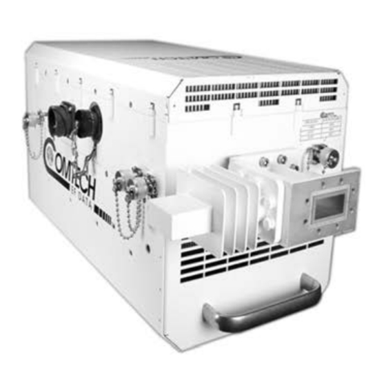
Chapter 4. ETHERNET INTERFACE OPERATION Sect. 4.5.4.6 Status | Trending Graphs Figure C-1. Comtech EF Data LPOD Outdoor Amplifiers / BUCs The fans used by CEFD’s LPOD family of Outdoor Amplifiers / BUCs (Figure C-1) are designed for long life, even in harsh environments. Still, they are mechanical devices, subject to wear, and may need replacement after several years. -
Page 224: Clean The Lpod Ps 1 Heat Sinks
Low Power Outdoor (LPOD) Amplifier/Block Up Converter (BUC) Revision 15 Clean the LPOD PS 1 Heat Sinks To clean the LPOD PS 1 Heatsinks, do these steps: Step Task Disconnect power from the LPOD. Remove the eight screws – four on either side of the fan shroud – see Figure C-3. Make sure that you use the correct screwdriver to avoid damaging the screws. - Page 225 Low Power Outdoor (LPOD) Amplifier/Block Up Converter (BUC) Revision 15 Figure C-3. LPOD PS 1 Shroud Screw Locations Appendix C C–3 MN-LPOD...
- Page 226 Low Power Outdoor (LPOD) Amplifier/Block Up Converter (BUC) Revision 15 Figure C-4. Fan Shroud Removal Figure C-5. Fan Power Supply Disconnection Appendix C C–4 MN-LPOD...
- Page 227 Low Power Outdoor (LPOD) Amplifier/Block Up Converter (BUC) Revision 15 Figure C-6. LPOD PS 1 Heat Sink Locations Figure C-7. Fan Power Supply Reconnection Appendix C C–5 MN-LPOD...
-
Page 228: Clean The Lpod Ps 1.5 Heat Sinks
Low Power Outdoor (LPOD) Amplifier/Block Up Converter (BUC) Revision 15 Clean the LPOD PS 1.5 Heat Sinks To clean the LPOD PS 1.5 Heatsinks, do these steps: Step Task Disconnect power from the LPOD. Remove the screws from all four sides of the LPOD as needed – see Figure C-8. Make sure that you use the correct screwdriver to avoid damaging the screws. - Page 229 Low Power Outdoor (LPOD) Amplifier/Block Up Converter (BUC) Revision 15 Figure C-8. LPOD PS 1.5 Shroud Screw Locations Figure C-9. Fan Shroud Removal Appendix C C–7 MN-LPOD...
- Page 230 Low Power Outdoor (LPOD) Amplifier/Block Up Converter (BUC) Revision 15 Figure C-10. Fan 1 / Fan 2 Power Supplies Disconnection Figure C-11. LPOD PS 1.5 Heat Sink Location Appendix C C–8 MN-LPOD...
- Page 231 Low Power Outdoor (LPOD) Amplifier/Block Up Converter (BUC) Revision 15 Figure C-12. Fan 1 / Fan 2 Power Supplies Reconnection Appendix C C–9 MN-LPOD...
-
Page 232: Clean The Lpod Ps 2 Heat Sinks
Low Power Outdoor (LPOD) Amplifier/Block Up Converter (BUC) Revision 15 Clean the LPOD PS 2 Heat Sinks To clean the LPOD PS 2 Heatsinks, do these steps: Step Task Disconnect the power source from the LPOD. Remove the screws from the sides and end of the LPOD as needed – see Figure C-13. Make sure that you use the correct screwdriver to avoid damaging the screws. - Page 233 Low Power Outdoor (LPOD) Amplifier/Block Up Converter (BUC) Revision 15 Figure C-13. LPOD PS 2 Shroud Screw Locations Figure C-14. Fan Shroud Removal Appendix C C–11 MN-LPOD...
- Page 234 Low Power Outdoor (LPOD) Amplifier/Block Up Converter (BUC) Revision 15 Figure C-15. Fan 1 / Fan 2 Power Supplies Disconnection Figure C-16. LPOD PS 2 Heat Sink Locations Appendix C C–12 MN-LPOD...
- Page 235 Low Power Outdoor (LPOD) Amplifier/Block Up Converter (BUC) Revision 15 Figure C-17. Fan 1 / Fan 2 Power Supplies Reconnection Appendix C C–13 MN-LPOD...
-
Page 236: Cable Sealing And Wrapping
Low Power Outdoor (LPOD) Amplifier/Block Up Converter (BUC) Revision 15 Cable Sealing and Wrapping Before you resume operation of your equipment, you MUST make sure that all external cable assemblies for the outdoor equipment are properly sealed and wrapped to prevent water intrusion. Failure to achieve water tight sealing and wrapping will result in possible performance degradation and even product failure. - Page 238 2114 85281 WEST TH STREET TEMPE ARIZONA 480 • 333 • 2200 PHONE 480 • 333 • 2161...
Need help?
Do you have a question about the LPOD Series and is the answer not in the manual?
Questions and answers