Sign In
Upload
Manuals
Brands
Comtech EF Data Manuals
Amplifier
LPOD PS 1.5
Comtech EF Data LPOD PS 1.5 Manuals
Manuals and User Guides for Comtech EF Data LPOD PS 1.5. We have
2
Comtech EF Data LPOD PS 1.5 manuals available for free PDF download: Installation And Operation Manual
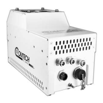
Comtech EF Data LPOD PS 1.5 Installation And Operation Manual (250 pages)
Outdoor Amplifier/Block Up Converter BUC, For Firmware Ver. 1.5.6 or Higher
Brand:
Comtech EF Data
| Category:
Amplifier
| Size: 8.13 MB
Table of Contents
Table of Contents
7
Table of Contents
9
Tables
13
Figures
14
Preface
19
About this Manual
19
Related Documents
19
Disclaimer
19
Conventions and References
20
Patents and Trademarks
20
Warnings, Cautions, Notes, and References
20
Examples of Multi-Hazard Notices
20
Recommended Standard Designations
21
Safety and Compliance
21
Electrical Safety and Compliance
21
Installation Guidelines Regarding Power Line Quality
21
Product Support
22
Comtech EF Data Headquarters
22
Warranty Policy
23
Limitations of Warranty
23
Exclusive Remedies
24
Chapter 1. Introduction
25
Overview
25
Figure 1-1. Comtech EF Data LPOD Outdoor Amplifiers / Bucs
25
Functional Description
26
Features
26
The Solid-State Advantage
26
Enhanced Standard Features
26
Built-In Redundancy Controller
27
Smart BUC" Functionality
27
Data Logging Capability
27
Optional Internal 10 Mhz Reference
28
Optional LNB Support
28
Theory of Operation
28
SSPA Block Diagrams
28
Figure 1-2. LPOD PS 1/1.5 Block Diagram
29
Figure 1-3. LPOD PS 2 Block Diagram
30
SSPA Module
31
Cooling System
31
Power Supply
31
LNB Operation
32
Block up Converter (BUC) Input
32
Monitor and Control (M&C)
32
Summary of Specifications
34
Characteristics
34
Optional Internal Reference
36
Optional LNB Bias / Reference
36
Environmental
36
Physical
37
Dimensional Envelopes
38
LPOD PS 1 Dimensional Envelopes
39
Figure 1-4. LPOD PS 1 C-Band Dimensional Envelope (Coax Output)
39
Figure 1-5. LPOD PS 1 C-Band Dimensional Envelope (Coax Output) - Reduced
40
Figure 1-6. LPOD PS 1 C-Band Dimensional Envelope
41
Figure 1-7. LPOD PS 1 X-Band Dimensional Envelope
42
Figure 1-8. LPOD PS 1 Ku-Band Dimensional Envelope
43
Figure 1-9. LPOD PS 1 Ku-Band Dimensional Envelope - Reduced Height Unit
44
LPOD PS 1.5 Dimensional Envelopes
45
Figure 1-10. LPOD PS 1.5 C-Band Dimensional Envelope (DC Option)
45
Figure 1-11. LPOD PS 1.5 C-Band Dimensional Envelope (AC Option)
46
Figure 1-12. LPOD PS 1.5 X-Band Dimensional Envelope
47
Figure 1-13. LPOD PS 1.5 Ku-Band Dimensional Envelope
48
LPOD PS 2 Dimensional Envelopes
49
Figure 1-14. LPOD PS 2 C-Band Dimensional Envelope
49
Figure 1-15. LPOD PS 2 X-Band Dimensional Envelope
50
Figure 1-16. LPOD PS 2 Ku-Band Dimensional Envelope
51
Chapter 2. System Connectors, Installation, and Startup
54
Water Tight Sealing
54
Customer Cable Assemblies
54
LPOD Interface Connectors
55
Figure 2-1. LPOD PS 1 Connectors
55
Figure 2-2. LPOD PS 1.5 Connectors
55
Connector 'J1 | LBAND IN' or 'J1 | Tx in
56
Connector 'J2 | RF out
56
Table 2-1. 'J2 | RF OUT' Interface Type
56
Connector 'J3 | POWER IN' AC Power Mains
57
LPOD PS 1, PS 1.5 'J3 | POWER IN' AC Power Main
58
Table 2-2. LPOD PS 1/PS 1.5 'J3 | POWER IN' Pin Assignments
58
Table 2-3. LPOD PS 2 'J3 | POWER IN' Pin Assignments
58
Connector 'J3 | POWER IN' DC Power Mains
59
LPOD PS 1 'J3 | POWER IN' DC Power Main
59
Table 2-4. LPOD PS 1 'J3 | POWER IN' Pin Assignments
59
LPOD PS 1.5 'J3 | POWER IN' DC Power Main
60
LPOD PS 2 'J3 | POWER IN' DC Power Main
60
Table 2-5. LPOD PS 1.5 'J3 | POWER IN' Pin Assignments
60
Table 2-6. LPOD PS 2 'J3 | POWER IN' Pin Assignments
60
Table 2-7. LPOD PS 2 'J3 | POWER IN' 48VDC Pin Assignments
61
Connector 'J6 | COM1' (Remote Communications and Discrete Control Port)
62
Table 2-8. LPOD 'J6 | COM1' Pin Assignments
62
About Circular Connectors
63
Connector 'J9 | OUTPUT SAMPLE' (PS 2 ONLY)
64
Connectors 'J10 | MODEM Rx' and 'J11 | LNB' (Optional Interfaces)
64
Ground Connector
65
LPOD Standalone (Single-Thread) Installations
66
Manpower Requirements
66
Typical Required Installation Tools
66
Pole-Mounted Installations
67
PL/12319-1 Universal Pole Mounting Kit
68
Figure 2-8. Universal Pole Mounting Kit – Final Assembly
70
KT-0000095 Single Unit Mounting Kit (LPOD PS 1, PS 1.5)
71
KT-0000125 Single Unit Mounting Kit (LPOD PS 2)
72
Spar-Mounted Installations (LPOD PS 1, PS 1.5)
73
Figure 2-12. LPOD PS 1, PS 1.5 Spar Mount Installation Kits
74
Shelf-Mounted Installations (LPOD PS 2)
75
Set the LPOD Power on
76
Chapter 3. Firmware Update
77
Firmware Update Overview
77
LPOD Firmware Update Procedure Summary
77
About Firmware Numbers, File Versions, and Formats
78
Prepare for the Firmware Download
78
Required User-Supplied Items
78
LPOD Connections
79
Configure the Terminal Emulator Program
80
Get the LPOD Management IP Address and Firmware Information
81
Use the HTTP Interface to Find the Firmware Information
81
Use the Serial Interface to Find the Firmware Information
82
Make a Temporary Folder (Subdirectory) on the User PC
83
Use Windows Desktop to Make a Folder
83
Use Windows Explorer to Make a Folder
84
Use the Run and Browse Windows to Make a Folder
84
Use Windows Command-Line or Command Prompt to Make a Folder
85
Download and Extract the Firmware Update Files
86
Use Windows Desktop to View Folder Contents
88
Use Windows Command-Line to View Folder Contents
88
Upload the Firmware Files and Update the LPOD Unit
88
Important Considerations
88
Steps to FTP Upload the Firmware Files
89
OPTIONAL: Steps to "Creflash" Upload the Firmware Files
90
Steps to Update the LPOD Unit
91
Chapter 4. Ethernet Interface Operation
93
Overview
93
Prerequisites
93
SNMP Interface
94
Management Information Base (MIB) Files
94
Comtechefdata Root MIB File
94
LPOD MIB File
95
LPOD Traps MIB File
95
SNMP Community Strings
95
SNMP Traps
95
Telnet Interface
98
Using Hyperterminal for Telnet Remote Control Operation
98
Configure Hyperterminal for Telnet Remote Control Operation4-7
99
Figure 4-2. Telnet Interface Example – Hyperterminal
99
HTTP (Web Server) Interface
100
Enable the HTTP Interface
100
Figure 4-4. Open Windows Command-Line
100
Figure 4-5. Telnet Login and Remote Command Execution
101
HTTP Interface User Login
102
Figure 4-6. LPOD HTTP Interface "Splash" Page Example
102
HTTP Interface Features
103
Menu Tree
103
Page Navigation
103
Page Sections
103
Action Buttons
104
Drop-Down Lists
104
Text or Data Entry
104
HTTP Interface Page Examples and Descriptions
105
Home
105
Home | Home
105
Home | Contact
106
Home | Support
107
Admin (Administration)
108
Admin | Access
108
Admin | SNMP
110
Config
111
Config | Amplifier
111
Config | LNB
113
Config | Utility
115
Config | Redundancy
117
Status
118
Status | Summary
118
Status | Status
119
Figure 4-19. 'Status | Fets' Page
120
Status | Events
121
Status | Statistics
123
Status | Trending Graphs
125
Chapter 5. Serial Interface Operation
131
Overview
131
Key Operational Parameters / Common Commands and Queries
131
RF Input Level
131
Attenuator Control
132
Mute Control
132
Faults
132
Power Detector
133
Common Queries
133
End-Of-Life Commands/Queries
134
Remote Control Protocol and Structure
134
Basic Serial Protocol
135
Eia-485
135
Basic Protocol
136
Packet Structure
136
Start of Packet
137
Target Address
137
Address Delimiter
137
Instruction Code
137
Instruction Code Qualifier
138
Controller-To-Target Rules
138
Target-To-Controller Rules
138
Optional Message Arguments
139
End of Packet
139
Remote Commands and Queries
140
Appendix A. 1:1 Redundancy
163
LPOD Redundancy Operation Overview
163
1:1 Redundancy Mode
164
Ethernet-Based Monitor and Control
164
1:1 Redundancy System Setup (Using a Single Ethernet Interface
165
Serial-Based Monitor and Control
166
Figure A-2. Serial-Based M&C Using CEFD Kit KT-0020518
166
Table A-1. OFM Online-To-Offline Operational Settings Conveyance
169
Applicable Serial-Based Redundancy Commands and Queries
170
Troubleshooting Connectivity Issues
170
1:1 Redundancy System Cabling and Installation
172
Water Tight Sealing
172
Figure A-3. Typical LPOD 1:1 Redundancy System Cabling Schematic
173
1:1 Redundancy System Assembly Kit Examples
174
Common Kit Examples
175
Assembled Isometric Views
176
Table A-2. Parts List for KT-0000098 LPOD C-Band Rx Switch Kit
178
Figure A-6. KT-0000098 LPOD C-Band Rx Switch Kit Example – Exploded Isometric View
179
Figure A-7. KT-0000098 LPOD C-Band Rx Switch Kit Example – Assembled Isometric View
180
Table A-3. Parts List for PL/7596-1 LPOD Ku-Band Rx Switch Kit
182
Figure A-8. PL/7596-1 LPOD Ku-Band Rx Switch Kit Example – Exploded Isometric View
183
Figure A-10. KT-0000191 Ku-Band Rx Switch Kit Example, OMT-Mounted, Metric Exploded Isometric View
187
Figure A-11. KT-0000191 Ku-Band Rx Switch Kit Example, OMT-Mounted, Metric Assembled Isometric View
188
LPOD PS 1 1:1 Redundancy Kit Examples
190
Exploded Isometric View
191
Assembled Isometric View
192
Example – Exploded Isometric View
195
Figure A-15. KT-0000090 LPOD PS 1 C-Band Coax Output 1:1 Redundancy Kit Example – Assembled Isometric View
196
Exploded Isometric View
199
Assembled Isometric View
200
Exploded Isometric View
203
Assembled Isometric View
204
LPOD PS 1.5 1:1 Redundancy Kit Examples
206
Figure A-20. KT-0020526 LPOD PS 1.5 C-Band DC Option 1:1 Redundancy Kit Example – Exploded Isometric Views, Steps 1 & 2
207
Figure A-21. KT-0020526 LPOD PS 1.5 C-Band DC Option 1:1 Redundancy Kit Example – Exploded Isometric View, Step 3
208
Figure A-22. KT-0020526 LPOD PS 1.5 C-Band DC Option 1:1 Redundancy Kit Example – Assembled Isometric View
209
Exploded Isometric View
211
Assembled Isometric View
212
LPOD PS 2 1:1 Redundancy Kit Examples
214
Assembled Views
215
Exploded Isometric View
217
Assembled Isometric View
218
Exploded Isometric View
221
Assembled Isometric View
222
Appendix B. Cable Drawings
223
Overview
223
Control and Data Cables
224
Serial Interface Cable
225
Ethernet Interface Cable
226
19-Pin COMMS Cable (100
227
19-Pin COMMS Cable (250
228
Redundant Loop Cable - Rx / Tx
229
Redundant Loop Cable - Tx Only
230
RF Cables
232
B.3 RF Cables
232
RF Cable (Type 'N
233
Appendix C. Maintenance
235
Overview
235
Clean the LPOD PS 1 Heat Sinks
236
Figure C-3. LPOD PS 1 Shroud Screw Locations
237
Figure C-4. Remove the Fan Shroud
238
Figure C-6. LPOD PS 1 Heat Sink Locations
239
Clean the LPOD PS 1.5 Heat Sinks
240
Figure C-8. LPOD PS 1.5 Shroud Screw Locations
241
Figure C-9. Remove the Fan Shroud
242
Figure C-11. LPOD PS 1.5 Heat Sink Location
243
Clean the LPOD PS 2 Heat Sinks
244
Figure C-13. LPOD PS 2 Shroud Screw Locations
245
Figure C-15. Disconnect the Fan 1 / Fan 2 Power Supplies
246
Figure C-17. Reconnect the Fan 1 / Fan 2 Power Supplies
247
Water Tight Sealing
248
Advertisement
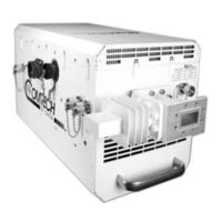
Comtech EF Data LPOD PS 1.5 Installation And Operation Manual (238 pages)
Outdoor Amplifier / Block Up Converter (BUC)
Brand:
Comtech EF Data
| Category:
Amplifier
| Size: 14.29 MB
Table of Contents
Table of Contents
3
Preface
13
About this Manual
13
Related Documents
13
Disclaimer
13
Conventions and References
14
Patents and Trademarks
14
Warnings, Cautions, Notes, and References
14
Examples of Multi-Hazard Notices
14
Recommended Standard Designations
14
Safety and Compliance
15
Electrical Safety and Compliance
15
Installation Guidelines Regarding Power Line Quality
15
Product Support
16
Comtech EF Data Headquarters
16
Warranty Policy
16
Limitations of Warranty
16
Exclusive Remedies
17
Chapter 1. Introduction
19
Overview
19
Figure 1-1. LPOD Outdoor Amplifiers / Bucs
19
Functional Description
20
Features
20
The Solid-State Advantage
20
Enhanced Standard Features
20
Built-In Redundancy Controller
20
Smart BUC" Functionality
21
Data Logging Capability
21
Optional Internal 10 Mhz Reference
21
Optional LNB Support
21
Theory of Operation
22
SSPA Block Diagrams
22
Figure 1-2. LPOD PS 1 and PS 1.5 Block Diagram
22
Figure 1-3. LPOD PS 2 Block Diagram
23
SSPA Module
24
Cooling System
24
Power Supply
24
LNB Operation
24
Block up Converter (BUC) Input
25
Monitor and Control (M&C)
25
Table 1-1. Low Oscillator (LO) Frequencies
25
Summary of Specifications
26
Characteristics
26
Optional Internal Reference
28
Optional LNB Bias / Reference
28
Environmental
28
Physical
29
Dimensional Envelopes
31
LPOD PS 1 Dimensional Envelopes
32
Figure 1-4. LPOD PS 1 C-Band Dimensional Envelope (Coax Output)
32
Figure 1-5. LPOD PS 1 C-Band Dimensional Envelope (Coax Output) - Reduced Height Unit
33
Figure 1-6. LPOD PS 1 C-Band Dimensional Envelope
34
Figure 1-7. LPOD PS 1 X-Band Dimensional Envelope
35
Figure 1-8. LPOD PS 1 Ku-Band Dimensional Envelope
36
Figure 1-9. LPOD PS 1 Ku-Band Dimensional Envelope - Reduced Height Unit
37
LPOD PS 1.5 Dimensional Envelopes
38
Figure 1-10. LPOD PS 1.5 C-Band Dimensional Envelope (DC Option)
38
Figure 1-11. LPOD PS 1.5 C-Band Dimensional Envelope (AC Option)
39
Figure 1-12. LPOD PS 1.5 X-Band Dimensional Envelope
40
Figure 1-13. LPOD PS 1.5 Ku-Band Dimensional Envelope
41
LPOD PS 2 Dimensional Envelopes
42
Figure 1-14. LPOD PS 2 C-Band Dimensional Envelope
42
Figure 1-15. LPOD PS 2 X-Band Dimensional Envelope
43
Figure 1-16. LPOD PS 2 Ku-Band Dimensional Envelope
44
Chapter 2. System Connectors, Installation, and Startup
45
Overview
45
Cable Sealing and Wrapping
46
Water Tight Sealing
46
Customer Cable Water Tight Sealing
46
Figure 2-1. Water Tight Cable End Example
46
Cable Wrapping
47
Connectors and Cables
48
Figure 2-2. PS 1 Connectors
48
Figure 2-3. PS 1.5 Connectors
48
Figure 2-4. PS 2 Connectors
48
Connector 'J1 | LBAND IN' or 'J1 | Tx in
49
Connector 'J2 | RF out
49
Table 2-1. 'J2 | RF OUT' Interface Type
49
Connector 'J3 | POWER IN' AC Power Mains
50
PS 1, PS 1.5 'J3 | POWER IN' AC Power Main
50
Table 2-2. PS 1/PS 1.5 'J3 | POWER IN' Pin Assignments
50
PS 2 'J3 | POWER IN' AC Power Main
51
Table 2-3. PS 2 'J3 | POWER IN' Pin Assignments
51
Connector 'J3 | POWER IN' DC Power Mains
52
PS 1 'J3 | POWER IN' DC Power Main
52
Table 2-4. PS 1 'J3 | POWER IN' Pin Assignments
52
PS 1.5 'J3 | POWER IN' DC Power Main
53
PS 2 'J3 | POWER IN' DC Power Main
53
Table 2-5. PS 1.5 'J3 | POWER IN' Pin Assignments
53
Table 2-6. PS 2 'J3 | POWER IN' Pin Assignments
53
PS 2 'J3 | POWER IN' 48 VDC Power Main Option
54
Table 2-7. PS 2 'J3 | POWER IN' 48 VDC Pin Assignments
54
Connector 'J6 | COM1' (Remote Communications and Discrete Control Port)
55
Table 2-8. 'J6 | COM1' Pin Assignments
55
Circular Connectors
56
Connector 'J9 | OUTPUT SAMPLE' (PS 2 Only)
57
Connectors 'J10 | MODEM Rx' and 'J11 | LNB' (Optional Interfaces)
57
Figure 2-6. 'J10 | Modem Rx' and 'J11 | LNB' Connectors
57
Figure 2-7. Ground Connector Locations
57
Ground Connector
57
Figure 2-5. Circular Connector Example
56
LPOD Standalone (Single-Thread) Installations
58
Manpower Requirements
58
Typical Required Installation Tools
58
Pole-Mounted Installations
58
Universal Pole Mounting Kit (PL/12319-1)
59
Figure 2-8. Universal Pole Mounting Kit (PL/12319-1)
59
Figure 2-9. Universal Pole Mounting Kit - Final Assembly
61
Single Unit Mounting Kit (KT-0000095) for PS 1, PS 1.5
62
Single Unit Mounting Kit (KT-0000125) for PS 2
63
Spar-Mounted Installations for PS 1, PS 1.5
64
Figure 2-12. SSPA Spar Mount Installation Example
64
Shelf-Mounted Single Unit Kit (KT-0020524) for PS 2
66
LPOD Power Setting
67
Chapter 3. Firmware Update
69
Firmware Update Overview
69
Firmware Update Procedure Summary
69
About Firmware Numbers, File Versions, and Formats
70
Prepare for the Firmware Download
71
Required User-Supplied Items
71
LPOD Connections
71
Figure 3-1. Standalone or Redundant Serial Connectio
71
Figure 3-2. Standalone or Redundant Ethernet Connection
72
Configure the Terminal Emulator Program
73
Get the LPOD Management IP Address and Firmware Information
73
Use the HTTP Interface to Find the Firmware Information
73
Use the Serial Interface to Find the Firmware Information
74
Make a Temporary Folder (Subdirectory) on the User PC
75
Use Windows Desktop to Make a Folder
75
Use Windows Explorer to Make a Folder
76
Use the Run and Browse Windows to Make a Folder
76
Use Windows Command-Line or Command Prompt to Make a Folder
77
Download and Extract the Firmware Update Files
77
Use Windows Desktop to View Folder Contents
79
Use Windows Command-Line to View Folder Contents
79
Upload the Firmware Files and Update the LPOD Unit
80
Important Considerations
80
Steps to FTP Upload the Firmware Files
80
Creflash" Utility Upload (Optional)
81
LPOD Unit Firmware Updates
82
Overview
83
Prerequisites
83
Chapter 4. Ethernet Interface Operation
83
SNMP Interface
84
MIB Files
84
CEFD Root MIB File
84
LPOD MIB File
84
LPOD Traps MIB File
84
SNMP Community Strings
85
SNMP Traps
85
Telnet Interface
88
Figure 4-1. Telnet Interface Example - Windows Command-Line
88
Using Hyperterminal for Telnet Remote Control Operation
89
Figure 4-2. Telnet Interface Example - Hyperterminal
89
Configure Hyperterminal for Telnet Remote Control Operation
90
Figure 4-3. Configure Hyperterminal
90
HTTP (Web Server) Interface
91
Enable the HTTP Interface
91
HTTP Interface User Login
93
Figure 4-4. LPOD HTTP Interface "Splash" Page Example
93
HTTP Interface Features
94
Menu Tree
94
Page Navigation
94
Page Sections
94
Action Buttons
94
Figure 4-5. LPOD HTTP Interface Menu Tree
94
Drop-Down Lists
95
Text or Data Entry
95
HTTP Interface Page Examples and Descriptions
96
Home
96
Home | Home
96
Figure 4-6. LPOD 'Home | Home' Page (PS .5 Unit Example Shown)
96
Home | Contact
97
Figure 4-7. 'Home | Contact' Page
97
Home | Support
98
Figure 4-8. 'Home | Support' Page
98
Admin (Administration)
99
Admin | Access
99
Admin | SNMP
101
Config
102
Config | Amplifier
102
Config | LNB
104
Config | Utility
105
Config | Redundancy
107
Status
108
Status | Summary
108
Status | Status
109
Status | Fets
110
Status | Events
111
Status | Statistics
113
Status | Trending Graphs
114
Chapter 5. Serial Interface Operation
121
Overview
121
Key Operational Parameters / Common Commands and Queries
121
RF Input Level
121
Attenuator Control
121
Mute Control
122
Faults
122
Power Detector
123
Common Queries
123
End-Of-Life Commands/Queries
124
Remote Control Protocol and Structure
124
Basic Serial Protocol
125
Basic Protocol
126
Packet Structure
126
Start of Packet
127
Target Address
127
Address Delimiter
127
Instruction Code
128
Instruction Code Qualifier
128
Controller-To-Target Rules
128
Target-To-Controller Rules
128
Optional Message Arguments
129
End of Packet
129
Remote Commands and Queries
131
Appendix A. 1:1 Redundancy
163
LPOD Redundancy Operation Overview
163
1:1 Redundancy Mode
164
Ethernet-Based Monitor and Control
164
1:1 Redundancy System Setup (Using a Single Ethernet Interface
165
Serial-Based Monitor and Control
166
Table A-1. OFM Online-To-Offline Operational Settings Conveyance
168
Applicable Serial-Based Redundancy Commands and Queries
169
Troubleshooting Connectivity Issues
170
1:1 Redundancy System Cabling and Installation
171
Cable Sealing and Wrapping
171
1:1 Redundancy System Assembly Kit Examples
174
Common Kit Examples
175
KT-0020827 1:1 Free Standing Unitstrut Kit
175
KT-0000116 LPOD Rx Splitter / Cable Kit
176
KT-0000098 LPOD C-Band Rx Switch Kit
177
7596-1 LPOD Ku-Band Rx Switch Kit
180
KT-0000191 Ku-Band Rx Switch Kit Example, OMT-Mounted, Metric
183
LPOD PS 1 1:1 Redundancy Kit Examples
186
KT-0000104 LPOD PS 1 C-Band 1:1 Redundancy Kit
186
KT-0000090 LPOD PS 1 C-Band Coax Output 1:1 Redundancy Kit
189
KT-0000089 LPOD PS 1 Ku-Band 1:1 Redundancy Kit
192
KT-0000170 LPOD PS 1 X-Band 1:1 Redundancy Kit
195
LPOD PS 1.5 1:1 Redundancy Kit Examples
198
KT-0020526 LPOD PS 1.5 C-Band DC Option 1:1 Redundancy Kit
198
KT-0000060 LPOD PS 1.5 Ku-Band 1:1 Redundancy Kit
202
LPOD PS 2 1:1 Redundancy Kit Examples
205
KT-0020827 PS 2 C-Band 1:1 Redundancy Free Standing Kit
205
KT-0000091 LPOD PS 2 C-Band 1:1 Redundancy Kit
207
KT-0000254 LPOD PS 2 Ku-Band 1:1 Redundancy Kit
210
Appendix B. Cable Drawings
213
Overview
213
Control and Data Cables
214
Serial Interface Cable
215
Ethernet Interface Cable
216
19-Pin COMMS Cable (100
217
19-Pin COMMS Cable (250
218
Redundant Loop Cable - Rx / Tx
219
Redundant Loop Cable - Tx Only
220
RF Cables
221
RF Cable (Type 'N
222
Appendix C. Maintenance
223
Overview
223
Clean the LPOD PS 1 Heat Sinks
224
Clean the LPOD PS 1.5 Heat Sinks
228
Clean the LPOD PS 2 Heat Sinks
232
Cable Sealing and Wrapping
236
Advertisement
Related Products
Comtech EF Data LPOD PS 1
Comtech EF Data LPOD PS 2
Comtech EF Data PCB-4000A
Comtech EF Data LPOD-R PS .5
Comtech EF Data LPOD
Comtech EF Data LPOD-R PS 1
Comtech EF Data LPOD-R PS 1.5
Comtech EF Data LPOD-R Series
Comtech EF Data LPOD Series
Comtech EF Data PCB-4000
Comtech EF Data Categories
Modem
Switch
Amplifier
Network Router
Media Converter
More Comtech EF Data Manuals
Login
Sign In
OR
Sign in with Facebook
Sign in with Google
Upload manual
Upload from disk
Upload from URL