Table of Contents
Advertisement
Quick Links
CPA
C-Band Solid-State Power Amplifier
Installation and Operation Manual
Important Note: This information contained in this document supersedes the documentation for:
CPA-050, CPA-100, CPA-200, and CPA-350. Product specifications are subject to change without
prior notice.
Part Number MN/CPA-IN.IOM
Revision 0
Advertisement
Table of Contents
Troubleshooting

Related Manuals for Comtech EF Data CPA-050


Summary of Contents for Comtech EF Data CPA-050
- Page 1 C-Band Solid-State Power Amplifier Installation and Operation Manual Important Note: This information contained in this document supersedes the documentation for: CPA-050, CPA-100, CPA-200, and CPA-350. Product specifications are subject to change without prior notice. Part Number MN/CPA-IN.IOM Revision 0...
- Page 3 C-Band Solid-State Power Amplifier Installation and Operation Manual Part Number MN/CPA-IN.IOM Revision 0 January 7, 2005 Copyright © Comtech EF Data, 2005. All rights reserved. Printed in the USA. Comtech EF Data, 2114 West 7th Street, Tempe, Arizona 85281 USA, 480.333.2200, FAX: 480.333.2161.
- Page 4 4. To ensure that the product is not damaged during shipping, pack the product in its original shipping carton/packaging. 5. Ship the product back to Comtech EF Data. (Shipping charges should be prepaid.) This equipment was supplied with the latest internal operating software/firmware released for this model at time of shipment.
-
Page 5: Table Of Contents
Table of Contents CHAPTER 1 INTRODUCTION................1-1 Overview ......................1-1 Functional Description..................1-3 1.2.1 Front Panel ..................... 1-3 1.2.2 Front Panel Indicators................1-4 1.2.3 Built-in Redundancy Controller ............... 1-4 Specifications ....................1-5 CHAPTER 2. INSTALLATION ................... 2-1 Unpacking ......................2-1 Installation...................... - Page 6 C-Band Solid-State Power Amplifier Revision 0 Preface MN/CPA-IN.IOM CHAPTER 3. OPERATION ..................3-1 General ......................3-1 Operation......................3-3 3.2.1 SSPA Commands ................... 3-5 3.2.2 Configuration Menu ................3-9 3.2.3 Monitor Status Menu................3-11 3.2.4 Current Faults Menu ................3-13 3.2.5 Stored Faults Menu ................3-15 3.2.6 Utility Menu ...................
- Page 7 C-Band Solid-State Power Amplifier Revision 0 Preface MN/CPA-IN.IOM Command/Response Pairs ................5-9 5.9.1 Utility Commands..................5-9 5.9.2 Configuration Commands ..............5-10 5.9.3 Mode Commands ................. 5-11 5.9.4 Status Commands ................5-12 5.9.5 Stored Alarms ..................5-17 5.9.6 Error Processing ................... 5-18 5.9.7 Configuration Errors................
- Page 8 C-Band Solid-State Power Amplifier Revision 0 Preface MN/CPA-IN.IOM Figures Figure 1-1. CPA350..............................1-1 Figure 1-2. Functional Block Diagram ........................1-2 Figure 2-1. Redundancy Installation......................... 2-4 Figure 3-1. SSPA Operating Command Functions....................3-4 Figure 3-2A. Configuration Menu Commands (Single Configuration)..............3-7 Figure 3-3.
- Page 9 Preface MN/CPA-IN.IOM About this Manual This manual provides installation and operation information for the Comtech EF Data C-Band Solid-State Power Amplifier (CPA). This is a technical document intended for earth station engineers, technicians, and operators responsible for the operation and maintenance of the CPA.
- Page 10 C-Band Solid-State Power Amplifier Revision 0 Preface MN/CPA-IN.IOM Safety Notices This equipment has been designed to minimize exposure of personnel to hazards. The operators and technicians must: • Know how to work around, with, and on high voltage and high RF power level equipment.
- Page 11 MN/CPA-IN.IOM Reporting Comments or Suggestions Concerning this Manual Comments and suggestions regarding the content and design of this manual will be appreciated. To submit comments, please contact the Comtech EF Data Technical Publications Department: techpubs@comtechefdata.com European EMC Directive In order to meet the European Electro-Magnetic Compatibility (EMC) Directive (EN55022, EN50082-1), properly shielded cables for DATA I/O are required.
- Page 12 Disclaimer Comtech EF Data has reviewed this manual thoroughly in order that it will be an easy-to- use guide to your equipment. All statements, technical information, and recommendations in this manual and in any guides or related documents are believed...
-
Page 13: Chapter 1. Introduction
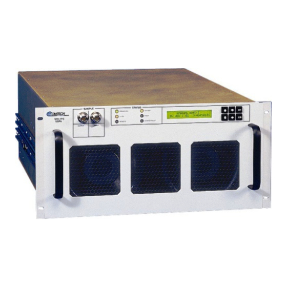
The CPA is designed to be hard mounted in a standard 19-inch (48 cm) rack or cabinet, or to be rack mounted using Comtech EF Data slide mechanisms provided with the CPA to allow it to be serviced without its removal from the rack. - Page 14 C-Band Solid-State Power Amplifier Revision 0 Introduction MN/CPA-IN.IOM CPA-050 CPA-100 CPA-200 CPA-350 Figure 1-1. CPA...
- Page 15 C-Band Solid-State Power Amplifier Revision 0 Introduction MN/CPA-IN.IOM A CPA-050 functional block diagram is shown in Figure 1-2. CPA 50 BLOCK DIAGRAM OUTPUT SAMPLE INPUT SAMPLE RF INPUT OUTPUT (W/G) CUST. TEMP. GAIN COMP. CTRL OUTPUT REFLECTED POWER POWER DETECTOR DETECTOR POWER CONDITIONING &...
- Page 16 C-Band Solid-State Power Amplifier Revision 0 Introduction MN/CPA-IN.IOM A CPA-100 functional block diagram is shown in Figure 1-3. Figure 1-3. CPA-100 Functional Block Diagram...
- Page 17 C-Band Solid-State Power Amplifier Revision 0 Introduction MN/CPA-IN.IOM A CPA-200 functional block diagram is shown in Figure 1-4 CPA200 BLOCK DIAGRAM OUTPUT SAMPLE INPUT SAMPLE RF INPUT OUTPUT (W/G) CUST. - 5V TEMP. GAIN COMP. CTRL OUTPUT REFLECTED 10V #1 POWER POWER DETECTOR...
- Page 18 C-Band Solid-State Power Amplifier Revision 0 Introduction MN/CPA-IN.IOM A functional block diagram is shown in Figure 1-5. CPA350 CPA350 BLOCK DIAGRAM BLOCK DIAGRAM OUTPUT OUTPUT SAMPLE SAMPLE INPUT INPUT SAMPLE SAMPLE Output A Output A Σ Σ RF INPUT RF INPUT Driver Driver Σ...
-
Page 19: Front Panel
C-Band Solid-State Power Amplifier Revision 0 Introduction MN/CPA-IN.IOM Front Panel The front panel contains a User Interface Key-Pad which is used by a local operator to input commands to the CPA. The keypad is used to select the configuration for operating and monitoring the status of the SSPA. -
Page 20: Front Panel Indicators
C-Band Solid-State Power Amplifier Revision 0 Introduction MN/CPA-IN.IOM 1.3.1 Front Panel Indicators There are six LED indicator lights on the front panel, which indicate the status of the SSPA and provide summary fault information. Refer to Table 1-2for description of the LED lamps: Table 1-2. -
Page 21: Specifications
1.25:1 maximum Connector Type N Output Frequency 5.845 to 6.425 GHz Power CPA-050: 47.0 dBm min @ 1 dB Compression CPA-100: 50.0 dBm min @ 1 dB Compression CPA-200: 53.0 dBm min @ 1 dB Compression CPA-350: 55.0 dBm min @ 1 dB Compression... - Page 22 Type N, 50 Ω, -40 dBc Input Sample Type N, 50 Ω, -20 dBc Remote Control COM Port RS-232 or RS-485 Protocol Comtech EF Data ASCII or Emulation Mode Alarms Summary Fault Form C Power On Green Fault Stored Faults...
-
Page 23: Chapter 2. Installation
Check to determine that all parts, materials and documentation have been shipped with the CPA. The CPA should be inspected for possible damage, and then tested for proper operation. • If the shipment exhibits any of the following, contact Comtech EF Data Customer Support: ♦ Incomplete ♦ Mechanical damage ♦... -
Page 24: Installation
C-Band Solid-State Power Amplifier Revision 0 Installation MN/CPA-IN.IOM Installation The CPA is designed for ease of installation; refer to Appendix B, Dimensional Drawings to determine type of installation by size of the CPA. Adequate air ventilation should be provided to the rack mounted equipment. Cool air is taken in through the front panel and exhausted out the rear panel. -
Page 25: External Connections
Chapter 3. EXTERNAL CONNECTIONS External Rear Panel Connections Refer to Table 2-1 for a list of the connectors on the rear panel. Table 2-1. Rear Panel Connectors Connector Description Mating Connecting CPA RF Input (RF IN) Type N (f) CPA RF Output (RF OUTPUT) CPR137G AC Prime Power Input (AC IN) IEC320 C-19... - Page 26 C-Band Solid-State Power Amplifier Revision 0 Installation MN/CPA-IN.IOM 3.1.1 Redundant Loop Interface, Connector J4 The Redundant Loop Interface connector J4 is a 19-pin circular connector, type MS3112E14-19S. The pin-out specification is contained in Table 3-2. This connector is used only in redundant configurations. Table 3-2.
- Page 27 C-Band Solid-State Power Amplifier Revision 0 Installation MN/CPA-IN.IOM 3.1.2 Customer Discrete Control, Connector J5 The Customer Discrete Control connector J5 is a 19-pin circular connector, type MS3112E14-19S. The pin-out specification is contained in Table 3-3 for 1:1 configuration and Table 3-4 for 1:2 configuration. Table 3-3.
- Page 28 C-Band Solid-State Power Amplifier Revision 0 Installation MN/CPA-IN.IOM 3.1.3 EIA-232/EIA-485 Interface, Connector J6 The EIA-232/EIA-485 Interface connector J6 is a 9-pin D type DB9F connector socket. The pin-out specifications are contained in Table 3-5. The mating connector is a DB9M. Table 3-5.
-
Page 29: Chapter 3. Operation
Chapter 4. OPERATION Introduction The front panel of the CPA has a keypad for the operator input commands, an LCD Display, LED status indicators, and connector test sample ports to monitor the RF input and output signals. - Page 30 C-Band Solid-State Power Amplifier Revision 0 Operation MN/CPA-IN.IOM 4.1.1 Switching On Before applying AC power to the unit, make sure the waveguide output of the amplifier is properly loaded or terminated. Failure to do so could lead to equipment damage and excessive RF radiation levels. WARNING Prior to positioning the Prime Power Switch to On, perform the following: 1.
-
Page 31: Operation
C-Band Solid-State Power Amplifier Revision 0 Operation MN/CPA-IN.IOM Operation Local control of the CPA is controlled by operator input commands initiated through the six-button keypad on the front panel. The keypad is the local operator’s interface to control, configure and monitor the status of the CPA. Operator inputs and commands entered into the keypad are displayed by the front panel, 24-character, 2-line LCD display. - Page 32 C-Band Solid-State Power Amplifier Revision 0 Operation MN/CPA-IN.IOM CPA Commands The CPA commands (Figure 4-1through Figure 4-10) are presented in a tree structured menu format designed for access and execution of all control functions and to prevent the execution of an invalid entry by the operator. When the prime power is turned On, the LCD display will contain a message indicating the CPA model number and the version number of the firmware installed in the CPA.
- Page 33 C-Band Solid-State Power Amplifier Revision 0 Operation MN/CPA-IN.IOM ENTER ENTER ---- CPA050-5964-I ----- ---- CPA050-5964-I ----- ---- CPAXXX-XXXX-X ----- SW VER 1.02 SW VER 1.02 SW VER X.XX SN5964XXX SN5964XXX SNXXX --------- SELECT --------- --------- SELECT --------- --------- SELECT --------- --------- SELECT --------- --------- SELECT --------- --------- SELECT ---------...
- Page 34 C-Band Solid-State Power Amplifier Revision 0 Operation MN/CPA-IN.IOM Figure 4-2. Configuration Menu Commands (Single Configuration)
- Page 35 C-Band Solid-State Power Amplifier Revision 0 Operation MN/CPA-IN.IOM PRIORTY_SSPA= ---------SELECT--------- SSPA#1 SSPA#2** ----CONFIGURATION-MENU-- (see Notes) DOWN ENTER OPERATING MODE= - - - - - MANUAL- - - - - ATTENUATION = 10.00 db AMPLIFIER =-ON MUTE=--OFF SSPA #1 OFFSET +-0.00dB -ACTIVE BACKUP=NO (see Notes) ---ENTRY--MODE-=-REMOTE-...
-
Page 36: Configuration Menu
C-Band Solid-State Power Amplifier Revision 0 Operation MN/CPA-IN.IOM 4.3.1 Configuration Menu The Configuration Functions (Figure 4-2 or Figure 4-3)are as follows: Attenuation: Attenuation (ATTN): Input and displays the CPA attenuation setting which is selected between 0.00 to 20.00 in 0.25 dB steps. The default setting is 10.00 dB. Amplifier Amplifier: Control supply voltage to RF FETS. - Page 37 ENTER ENTER ENTER KEY-PAD KEY-PAD KEY-PAD DOWN DOWN DOWN DOWN DOWN LEFT LEFT LEFT LEFT LEFT --RF-FET----Q1-=-XXXmA-- --RF-FET----Q1-=-XXXmA-- --RF-FET----Q1-=-XXXmA-- --RF-FET----Q2-=-XXXmA-- --RF-FET----Q2-=-XXXmA-- --RF-FET----Q2-=-XXXmA-- ------------------------ ------------------------ ------------------------ ------------------------ DISPLAY DISPLAY DISPLAY ------------------------ ------------------------ ------------------------ ------------------------ Figure 4-4. CPA-050 Monitor Status Menu Commands...
- Page 38 C-Band Solid-State Power Amplifier Revision 0 Operation MN/CPA-IN.IOM ---------SELECT--------- ---------SELECT--------- --MONITOR-STATUS-MENU--- --MONITOR-STATUS-MENU--- -RF-FET----Q3-=-X.X-AMPS -RF-FET----Q3-=-X.X-AMPS DOWN DOWN DOWN -RF-FET----Q4-=-X.X-AMPS -RF-FET----Q4-=-X.X-AMPS ENTER ENTER -RF-FET----Q5-=-X.X-AMPS -RF-FET----Q5-=-X.X-AMPS -RF-FET----Q5-=-X.X-AMPS +12V=+12.2-----12V=-12.0 +12V=+12.2-----12V=-12.0 +12V=+12.2-----12V=-12.0 -RF-FET----Q6-=-X.X-AMPS -RF-FET----Q6-=-X.X-AMPS -RF-FET----Q6-=-X.X-AMPS --VCC=4.9------5V=-4.9-- --VCC=4.9------5V=-4.9-- --VCC=4.9------5V=-4.9-- ----28-VDC-PS-=-27.9---- ----28-VDC-PS-=-27.9---- ----28-VDC-PS-=-27.9---- -RF-FET----QX-=-X.X-AMPS -RF-FET----QX-=-X.X-AMPS -RF-FET----QX-=-X.X-AMPS 10VPS1=10.3 10VPS1=10.3 10VPS1=10.3 10VPS2=10.3...
- Page 39 C-Band Solid-State Power Amplifier Revision 0 Operation MN/CPA-IN.IOM ---------SELECT--------- ---------SELECT--------- --MONITOR-STATUS-MENU--- --MONITOR-STATUS-MENU--- -RF-FET----Q3-=-X.X-AMPS -RF-FET----Q3-=-X.X-AMPS DOWN DOWN DOWN -RF-FET----Q4-=-X.X-AMPS -RF-FET----Q4-=-X.X-AMPS ENTER ENTER -RF-FET----Q5-=-X.X-AMPS -RF-FET----Q5-=-X.X-AMPS -RF-FET----Q5-=-X.X-AMPS +12V=+12.2-----12V=-12.0 +12V=+12.2-----12V=-12.0 +12V=+12.2-----12V=-12.0 -RF-FET----Q6-=-X.X-AMPS -RF-FET----Q6-=-X.X-AMPS -RF-FET----Q6-=-X.X-AMPS --VCC=4.9------5V=-4.9-- --VCC=4.9------5V=-4.9-- --VCC=4.9------5V=-4.9-- ----28-VDC-PS-=-27.9---- ----28-VDC-PS-=-27.9---- ----28-VDC-PS-=-27.9---- -RF-FET----QX-=-X.X-AMPS -RF-FET----QX-=-X.X-AMPS -RF-FET----QX-=-X.X-AMPS 10VPS1=10.3 10VPS1=10.3 10VPS1=10.3 10VPS2=10.3...
- Page 40 C-Band Solid-State Power Amplifier Revision 0 Operation MN/CPA-IN.IOM Figure 4-7. CPA-350 Monitor Status Menu Commands 4-12...
-
Page 41: Monitor Status Menu
C-Band Solid-State Power Amplifier Revision 0 Operation MN/CPA-IN.IOM 4.3.2 Monitor Status Menu Monitors and displays the status (Figure 4-4, Figure 4-5, Figure 4-6, or Figure 4-7 of: • All CPA power supplies. • CPA internal temperature. • RF output power level. •... - Page 42 C-Band Solid-State Power Amplifier Revision 0 Operation MN/CPA-IN.IOM * May vary from model-to-model. ---------SELECT--------- ---------SELECT--------- ---------SELECT--------- --CURRENT-FAULTS-MENU--- --CURRENT-FAULTS-MENU--- --CURRENT-FAULTS-MENU--- DOWN DOWN DOWN DOWN ENTER ENTER ENTER POWER-FAULTS:----+12V=OK POWER-FAULTS:----+12V=OK POWER-FAULTS:----+12V=OK -12V=OK--VCC=OK---5V=OK- -12V=OK--VCC=OK---5V=OK- -12V=OK--VCC=OK---5V=OK- -----28-VDC-PS-=-OK----- -----28-VDC-PS-=-OK----- -----28-VDC-PS-=-OK----- --10VPS=OK-- --10VPS=OK-- --10VPS=OK-- ---AMPLIFIER-TEMP-=-OK-- ---AMPLIFIER-TEMP-=-OK-- ---AMPLIFIER-TEMP-=-OK-- LEGEND LEGEND...
-
Page 43: Current Faults Menu
4.3.6 Fan Fault CPA-050/100/200: Displays status of Fan #1 and Fan #2. CPA-350: Displays status of Fan #1, Fan #2, Fan #3, and Fan #4. IMPORTANT If a fault is reported, either fan or both could be faulted. For example: if Fan 1_2 =FT, this could mean that either Fan 1 or Fan 2 is faulted , or both Fan 1 and Fan 2 are faulted. - Page 44 C-Band Solid-State Power Amplifier Revision 0 Operation MN/CPA-IN.IOM 4.3.7 CPA-350 Only: Isolator Load Temperature Fault The output RF isolator load temperature is monitored for excessive reflected power that may cause the isolator load to overheat. If approximately > 100W of power is reflected, a fault will be reported and the unit will mute.
-
Page 45: Stored Faults Menu
C-Band Solid-State Power Amplifier Revision 0 Operation MN/CPA-IN.IOM 4.3.8 Stored Faults Menu The CPA displays a total of 100 faults with a date and time stamped and stored in memory as they occur. The stored faults (Figure 4-9) remain in memory until a clear command is entered. - Page 46 C-Band Solid-State Power Amplifier Revision 0 Operation MN/CPA-IN.IOM ---------SELECT--------- ---------SELECT--------- ---------SELECT--------- --UTILITY-FUNCTIONS-MENU--- --UTILITY-FUNCTIONS-MENU--- --UTILITY-FUNCTIONS-MENU--- DOWN DOWN DOWN DOWN ENTER ENTER ENTER FORWARD -RF-POWER-MONITOR FORWARD -RF-POWER-MONITOR FORWARD -RF-POWER-MONITOR ----OFFSET-=-+0.0dBm---- ----OFFSET-=-+0.0dBm---- ----OFFSET-=-+0.0dBm---- ----TIME:- 10:20:05AM---- ----TIME:- 10:20:05AM---- ----TIME:- 10:20:05AM---- -----DATE--09/15/94------ -----DATE--09/15/94------ -----DATE--09/15/94------ REVERSE-RF-POWER-MONITOR REVERSE-RF-POWER-MONITOR REVERSE-RF-POWER-MONITOR ----OFFSET-=-+0.0dBm----...
-
Page 47: Utility Menu
C-Band Solid-State Power Amplifier Revision 0 Operation MN/CPA-IN.IOM 4.3.9 Utility Menu The local operator can input commands to the following Utility Functions (Figure 4-10), which are displayed on the LCD display: Time Military time is displayed in hours, minutes, and seconds. Date The date is displayed in month, day, and year. - Page 48 C-Band Solid-State Power Amplifier Revision 0 Operation MN/CPA-IN.IOM This page is intentionally left blank. 4-20...
-
Page 49: Chapter 4. Redundant Configuration
CONFIGURATION Introduction Comtech EF Data CPA’s are designed to operate in both stand-alone and redundant configurations. Every CPA contains the circuitry and logic necessary to perform all the functions of a backup controller in both a 1:1 and 1:2 configuration. This includes the ability to monitor and control up to two RF waveguide switch assemblies. - Page 50 C-Band Solid-State Power Amplifier Revision 0 Redundant Configuration MN/CPA-IN.IOM Figure 5-1. Control Cabling of a 1:1 System The position of the waveguide/coax switch also is automatically changed to route the signal through the backup unit, thereby minimizing the loss of traffic. Control cable assemblies are required to set up either a 1:1 or a 1:2 system (other RF coaxial cables and waveguides are required as shown in Figure 5-1).
- Page 51 C-Band Solid-State Power Amplifier Revision 0 Redundant Configuration MN/CPA-IN.IOM The second control cable attaches from the Backup Unit J7 to the Waveguide switch. Figure 5-2. Control Cabling of a 1:2 System...
- Page 52 C-Band Solid-State Power Amplifier Revision 0 Redundant Configuration MN/CPA-IN.IOM 5.2.1 Gain Equalization of Redundant Units Typical procedures to equalize the gain between the Backup Unit and the Online Unit(s) via the Gain Offset adjustment in the backup unit’s CONFIGURATION Menu are as follows: Note: Ensure all connections are made as outlined previously in Sections 2 and 4.
- Page 53 C-Band Solid-State Power Amplifier Revision 0 Redundant Configuration MN/CPA-IN.IOM Case 1. Backup < Online unit(s). 1. Ensure the online unit attenuation is set to a value in dB greater than or equal (≥) to the difference in levels measured above. 2.
- Page 54 Setting Optional: Redundancy Kit Installation Comtech EF Data CPA’s are easily configured for redundant systems by using one of the optional Redundant Cable Kits. These kits include all the necessary controls, semi-rigid, and waveguide cabling, and appropriate waveguide/coax switches and terminations.
- Page 55 C-Band Solid-State Power Amplifier Revision 0 Redundant Configuration MN/CPA-IN.IOM Figure 5-3. Typical Redundancy Installation...
- Page 56 C-Band Solid-State Power Amplifier Revision 0 Redundant Configuration MN/CPA-IN.IOM Table 5-1. Redundancy Kit Item No. Part No. Nomenclature AS/0267 CPA050 /CPA350 CPA CA/RF0072 Cable, SW P4 to Upper J1, Red Kit, 1:1 CA/RF0074 Cable, SW P3 to Isolator, Red Kit. 1:1 CA/RF0073 Cable, SW P1 to Lower J1, Red Kit, 1:1 CA/WR0040...
- Page 57 C-Band Solid-State Power Amplifier Revision 0 Redundant Configuration MN/CPA-IN.IOM Item No. Part No. Nomenclature AS/0237 CPA100 CPA CA/RF0043 Cable, SW P4 to Upper J1, Red Kit, 1:1 CA/RF0044 Cable, SW P3 to Isolator, Red Kit. 1:1 CA/RF0045 Cable, SW P1 to Lower J1, Red Kit, 1:1 CA/WR0006 Cable, Redundant Loop CA/WR0007...
- Page 58 C-Band Solid-State Power Amplifier Revision 0 Redundant Configuration MN/CPA-IN.IOM This page is intentionally left blank. 5-10...
- Page 59 D R A W I N G R E V I S I O N R E C O R D Z O N E R E V P A G E D E S C R I P T I O N D A T E 15.38 19.00...
- Page 60 C-Band Solid-State Power Amplifier Revision 0 Redundant Configuration MN/CPA-IN.IOM Figure 2-3. Redundancy Outline Diagram...
-
Page 61: Chapter 5. Remote Control Specification
Chapter 6. REMOTE CONTROL COMMANDS General The backup CPA in the redundancy subsystem automatically monitors the configuration and status for each of the primary (chained) CPAs. This information is communicated via the dedicated serial interface between the CPAs. • If a primary CPA fails, the backup detects this event and automatically reconfigures itself to the proper attenuation setting and positions the waveguide switch to provide minimal loss of traffic. -
Page 62: Electrical Interface
C-Band Solid-State Power Amplifier Revision 0 Remote Control Commands MN/CPA-IN.IOM Electrical Interface The remote control interface supports either EIA-485 (2-wire), EIA-485 (4-wire) or EIA-232. The default port is EIA-485 (2-wire). Selection of the interface type is made via front panel menu selection. The three interface types are used alternately through the same 9-pin connector. -
Page 63: Cables
C-Band Solid-State Power Amplifier Revision 0 Remote Control Commands MN/CPA-IN.IOM Cables EIA-232 The remote control port is configured with pin 2 as the TX data signal (TD) and pin 3 as the RX data signal. This arrangement allows straight connection (pin 2 to pin 2 and pin 3 to pin 3) between the CPA and most standard serial ports using any standard EIA-232 cable (i.e. -
Page 64: Protocol
C-Band Solid-State Power Amplifier Revision 0 Remote Control Commands MN/CPA-IN.IOM Protocol Refer to Table 5-1 for protocol description. Protocol is divided into six subjects: • Transmission Mode • Baud Rate • Format • Character Set • Response Timeout • Bus Inactivity Requirements Table 6-1. -
Page 65: Access Methods
C-Band Solid-State Power Amplifier Revision 0 Remote Control Commands MN/CPA-IN.IOM Note: This can only be selected from the Front Panel Menu. Parity Bit Start Bit Stop Bit Data Bits Access Methods The CPA may be accessed directly by using a physical address or indirectly through a backup CPA in a redundant configuration using a virtual address. -
Page 66: Physical Address
C-Band Solid-State Power Amplifier Revision 0 Remote Control Commands MN/CPA-IN.IOM Addressess - the Device Address addresses All CPAs in a command. The Device Address consists of a physical address or a physical address plus a virtual address. 6.6.3 Physical Address Each CPA in the system must have a unique physical address regardless of the access method used. -
Page 67: Device Address
C-Band Solid-State Power Amplifier Revision 0 Remote Control Commands MN/CPA-IN.IOM 6.6.7 Device Address The Device Address consists of a Physical Address. For this document DEV is used for the generic case examples. For Example; <10 direct addressing <10V2 indirect addressing 6.6.8 Command A Command is a variable length character string beginning with a / and containing either... -
Page 68: End Of Message
C-Band Solid-State Power Amplifier Revision 0 Remote Control Commands MN/CPA-IN.IOM 6.7.2 End Of Message End of message strings were devised in such a way that an orderly screen presentation would result when simple ASCII terminals control CPAs. 6.7.2.1 Command Ending The end of message for a command is a carriage return. - Page 69 C-Band Solid-State Power Amplifier Revision 0 Remote Control Commands MN/CPA-IN.IOM CPA-200 Only: Utility Commands Command Explanation The SPB command will return either 3 or 4 bytes as: >SPB_ODD’cr’’lf’] or >SPB_EVEN’cr’’lf’] The query command for the SBR command has no parameters passed to the unit as shown in the manual, the manual will need to be corrected.
-
Page 70: Command/Response Pairs
C-Band Solid-State Power Amplifier Revision 0 Remote Control Commands MN/CPA-IN.IOM Utility Command/Response Pairs Time Set Time: <DEV/TIM_hh:mm:ss’cr’ Where: hh = Hour Confirmation: >DEV/TIM_hh:mm:ss ‘cr’’ lf’] mm = Minutes ss = Seconds Retrieve Time: <DEV/TIM_’cr’ Confirmation: >DEV/TIM_hh:mm:ss ‘cr’’ lf’] Note: 24-hour military is used. Date Set Date: <DEV/DAT_mm/dd/yy’cr’... -
Page 71: Configuration Commands
Retrieve AMP Status: <DEV/AMP_'cr' Confirmation: >DEV/AMP_xxx'cr'' lf'] The Comtech EF Data SSPA provides the user direct control of the 10VDC supply voltage to the solid-state RF power FETs. This feature provides the ability to put the SSPA into a low power consumption mode when the unit is offline. -
Page 72: Mode Commands
Automatic Mode. Redundancy Mode Comtech EF Data’s SSPA family is designed to automatically sense and configure into redundancy mode when the redundant loop cable is connected. Polling on the dedicated redundancy buss will not begin until the redundancy loop cable is connected. Each SSPA’s designation in a redundant subsystem is determined automatically via the redundancy interface cable connected between the two (1:1 subsystem) or three (1:2 subsystem) SSPAs in the redundant subsystem. -
Page 73: Status Commands
For 1:1 systems priority is always #1. Maintenance Maintenance Status: <DEV/RMS_’cr’ Where: Status Confirmation: >DEV/RMS_’cr’’ lf’] V+28_xx.x’cr’ +28 VDC Supply CPA-050 V+12xx.x’cr’ +12 VDC Supply V-12_xx.x’cr’ –12 VDC Supply V+5_x.x’cr’ +5 VDC Supply V–5_x.x’cr’ –5 VDC Supply V+10_xx.x’cr’ 10 VDC Supply TEMP_xx’cr’... - Page 74 RF Forward Power (dBm) RPWR_xx.x'cr' RF Reflected Power (dBm) FET Status FET Status: <DEV/RFS_’cr’ Where: Confirmation: >DEV/RFS_’cr’ CPA-050 only FET1_xxx’cr’ FET1 current in milliamperes FET2_xxx’cr’ FET2 current in milliamperes FET3_x.x’cr’ FET3 current in amperes FET4_x.x’cr’ FET4 current in amperes FET5_x.x’cr’...
- Page 75 C-Band Solid-State Power Amplifier Revision 0 Remote Control Commands MN/CPA-IN.IOM FET Status FET Status: <DEV/RFS_’cr’ Where : Confirmation: >DEV/RFS_’cr’ CPA-350 only FET1_C_xxx’cr’ FET1-C current in milliamps FET2_C_xxx’cr’ FET2-C current in milliamps FET3_C_x.x’cr’ FET3-C current in amps FET4_C_x.x’cr’ FET4-C current in amps FET4_1_x.x’cr’...
- Page 76 C-Band Solid-State Power Amplifier Revision 0 Remote Control Commands MN/CPA-IN.IOM Alarm Status Alarm Status: <DEV/RAS_'cr' Where: xx = OK or FT Confitmation: >DEV/RAS_'cr' CPA-050 +28_xx'cr' +28 VDC Fault +12_xx'cr' +12 VDC Fault –12_xx'cr' -12 VDC Fault +5_xx'cr' + 5 VDC Fault –5_xx'cr' –...
- Page 77 C-Band Solid-State Power Amplifier Revision 0 Remote Control Commands MN/CPA-IN.IOM Alarm Status Alarm Status: <DEV/RAS_'cr' Where: xx = OK or FT Confitmation: >DEV/RAS_'cr' CPA-350 +28_xx'cr' +28 VDC Fault +12_xx'cr' +12 VDC Fault –12_xx'cr' -12 VDC Fault +5_xx'cr' + 5 VDC Fault –5_xx'cr' –...
- Page 78 Where: Status Confirmation: >DEV/PACRFS_aabbccddeeffgg’cr’’lf'] aa = FET1 current in Hex, formular: CPA-050 FET1 = (aa * 3) mamps bb = FET2 current in Hex, formula: FET2 = (aa * 3) mamps cc = FET3 current in Hex, scaled 100mV per count...
- Page 79 C-Band Solid-State Power Amplifier Revision 0 Remote Control Commands MN/CPA-IN.IOM Packed FET Packed FET Status: <DEV/PACRFS_'cr' Where: Status Confirmation: >DEV/PACRFS_aabbccddeeffgghhiijjkkll aa = FET1- current in Hex, formular: mmnnooppqqrr'cr'' lf'] FET1 = (aa * 3) mamps bb = FET2 current in Hex, formula: CPA-200 FET2 = (aa * 3) mamps cc = FET3 current in Hex, scaled...
- Page 80 C-Band Solid-State Power Amplifier Revision 0 Remote Control Commands MN/CPA-IN.IOM Packed FET Packed FET Status: <DEV/PACRFS_'cr' Where: Status Confirmation: >DEV/PACRFS_aabbccddeeffgghhiijjkkll aa = FET1-C current in Hex, formula: mmnnooppqqrrssttuuvvwwxxyyzz112233 FET1 = (aa * 3) mamps 4455667788'cr'' lf'] bb = FET2-C current in Hex, formular: CPA-350 FET2 = (aa * 3) mamps cc = FET3-C current in Hex, scaled...
- Page 81 Status count above 10.0V in Hex bb = + 12 VDC supply scaled 100 mV count in Hex CPA-050 cc = - 12 VDC supply scaled 100mV count in Hex dd = + 5 VDC supply scaled –100mV countin Hex ee = - 5 VDC supply scaled –100mV...
- Page 82 >DEV/PACRAS_abcdefghijk'cr'' lf'] a = 1 if +28 Fault, else 0 b = 1 if +12 Fault, else 0 CPA-050 c = 1 if –12 Fault, else 0 d = 1 if + 5 Fault, else 0 e = 1 if – 5 Fault, else 0...
-
Page 83: Stored Alarms
C-Band Solid-State Power Amplifier Revision 0 Remote Control Commands MN/CPA-IN.IOM 6.9.1 Stored Alarms The 100 alarms are date/time stamped and stored in memory as they occur. The alarm entry also is updated with its date/time of clearance. The entry remains in memory until it is removed by command. -
Page 84: Time-Outs
C-Band Solid-State Power Amplifier Revision 0 Remote Control Commands MN/CPA-IN.IOM 6.7.6 Time-Outs A time-out should be assumed if there is no response in 1.0 seconds. The station monitor and control computer should try at least three times. Possible sources of time-outs are listed in Table 6-2 Table 6-2. - Page 85 Remote Control Commands C-Band Solid-State Power Amplifier Status Commands Retrieve Configuration Status <DEV/RCS_ 'cr' Retrieve Maintenance <DEV/RMS_ 'cr' Retrieve FET Status <DEV/RFS_ 'cr' Retrieve Utility Status <DEV/RUS_ 'cr' Retrieve Alarm Status <DEV/RAS_ 'cr' Summary Alarm Status <DEV/SAS_ 'cr' Terminal Status Change <DEV/TSC_ 'cr' Packed Configuration Status...
- Page 86 C-Band Solid-State Power Amplifier Remote Control Commands Notes: Revision 0 6-33...
-
Page 87: Chapter 6. Maintenance And Troubleshooting
Chapter 7. MAINTENANCE AND TROUBLESHOOTING General Refer to the block diagram in Section 1 for interconnecting cables and general troubleshooting help. -
Page 88: Maintenance Testing
C-Band Solid-State Power Amplifier Revision 0 Maintenance and Troubleshooting MN/CPA-IN.IOM Maintenance Testing The CPA is a C-Band CPA with an RF output level of +55.5 dBm at 1 dB compression. 7.2.1 Test Point Samples The RF input and output can be monitored at the RF Sample Test Points on the front panel. - Page 89 C-Band Solid-State Power Amplifier Revision 0 Maintenance and Troubleshooting MN/CPA-IN.IOM Table 7-1. Troubleshooting Symptom Possible Cause Solution Unit does not turn On Check power cord Ensure power cord is connected. (No display, No front connections. With input power cord disconnected, check panel lights, No fans) Faulty wiring to 28V wiring and connections to 28V power supply.
- Page 90 C-Band Solid-State Power Amplifier Revision 0 Maintenance and Troubleshooting MN/CPA-IN.IOM Table 7-1. Troubleshooting (Continued) Symptom Possible Cause Solution Mute function activated. Check the configuration menu to determine if No RF output or ≤ mute functions have been activated. Mute = output level.
- Page 91 C-Band Solid-State Power Amplifier Revision 0 Maintenance and Troubleshooting MN/CPA-IN.IOM Table 7-1. Troubleshooting (Continued) Symptom Possible Cause Solution Amplifier Temperature Note: Each CPA module contains an internal temperature monitor that Fault will shut off the unit (i.e. turn off the 10V supplies) if the Heatsink temperature becomes excessive.
- Page 92 C-Band Solid-State Power Amplifier Revision 0 Maintenance and Troubleshooting MN/CPA-IN.IOM This page is intentionally left blank.
-
Page 93: Appendix A. Parts List/Wiring Diagram
Appendix A. PARTS LIST/WIRING DIAGRAM Parts List The following table describes the part number, component description, and quanity per assembly for the SSPA. AS/0602 ASSEMBLY, TOP LEVEL, CPA350-5964-I Part Number Description AS/0200 1.00 EA ASSY, PCB AS/0206-FALCON 1.00 EA Assembly, Power AS/0605 1.00 EA ASSY, AMPLIFIER,... - Page 94 C-Band Solid-State power Amplifier Revision 0 Parts List/Wiring Diagram MN/CPA-IN.IOM Part Number Description CA/RB0072 1.00 EA CABLE, AUX PWR, CA/RB0073 1.00 EA CABLE, CNTL MODU CA/RB0074 1.00 EA CABLE, CNTL MODU CA/RB0075 1.00 EA CABLE, M&C CONTR CA/RF0060 2.00 EA CABLE, PWR MONIT CA/RF0150 1.00 EA...
- Page 95 C-Band Solid-State power Amplifier Revision 0 Parts List/Wiring Diagram MN/CPA-IN.IOM Part Number Description FP/BR0104 1.00 EA BRACKET, DUCT, M FP/BR0105 1.00 EA BRACKET, DUCT, M FP/BR0106 1.00 EA BRACKET,ACCESS P FP/BR0107 1.00 EA BRACKET,FAN DUCT FP/CV0052 1.00 EA COVER, TERMINAL FP/CV0137 2.00 EA COVER,FAN,HONEYC...
-
Page 96: Wiring Diagram
C-Band Solid-State power Amplifier Revision 0 Parts List/Wiring Diagram MN/CPA-IN.IOM Part Number Description HW/832X1-3/8SHCS 12.00 EA 8-32 X 1 3/8, SH HW/832X2-3/8SHCS-BL 6.00 EA 8-32 X 2 3/8, SH HW/HD10941A10322F 4.00 EA HANDLE, 5 IN, OV HW/HNVPH3810 2.00 EA HANDLE, SPRING D HW/JMP601RJS12 1.00 EA JUMPER, 12 POLE... - Page 97 C-Band Solid-State power Amplifier Revision 0 Parts List/Wiring Diagram MN/CPA-IN.IOM COMTECH COMM. CORP. PROPRIETARY- THIS DOCUMENT AND THE INFOR- REVISIONS REDUNDANT LOOP CONNECTOR, J4 DISCRETE CONTROL CONNECTOR, J5 SWITCH CONTROL CONNECTOR , J7 MATION DISCLOSED HEREIN ARE PROPRIETARY DATA OF COMTECH COMM. NEITHER THIS DOCUMENT NOR THE INFORMATION CONTAINED HEREIN SHALL BE REPRODUCED, USED OR DISCLOSED TO OTHERS WITHOUT THE ZONE...
- Page 98 C-Band Solid-State power Amplifier Revision 0 Parts List/Wiring Diagram MN/CPA-IN.IOM This page is intentionally blank. A–6 Rev. Revision 0...
- Page 99 Appendix B. DIMENSIONAL DRAWINGS The following dimensionally drawing represent the each CEFD CPA: • CPA-050 C-Band Solid-State Power Amplifier • CPA-100 C-Band Solid-State Power Amplifier (No Drawing at this time) • CPA-200 C-Band Solid-State Power Amplifier • CPA-350 C-Band Solid-State Power Amplifier...
- Page 100 ON LINE RF IN Tx ON FAULT CPA-50 SAMPLE 3.62 SSPA 2.39 4.36 REMOTE STORED FAULT RF SWITCH DISCRETE CONTROL 4.15 3.80 RF OUT COM 1 5.22 5.13 REDUNDANT LOOP AC IN 1.24 14.31 15.89 17.00 Figure B-1. CPA-050 Dimensional Drawing...
- Page 101 DISCRETE CONTROL DISCRETE CONTROL RF OUT RF OUT COM 1 COM 1 REDUNDANT LOOP REDUNDANT LOOP AC IN AC IN (CONTROL CABLES NOT SHOWN IN THIS VIEW) SSPA SWITCH RF IN RF OUT COAX SSPA Figure B-2. CPA-050 Dimensional Outline B–3...
- Page 102 C O N FI D EN T IA L C O N FI D EN T IA L E N G R CO PYR IG HT 2 000 COMTECH EF DATA C OR P. OUTLINE, 6RU MA TE R IA L : THIS DRA WING IS THE PROP ERTY OF C OMTECH E F DA TA CORP .
- Page 103 C-Band Solid-State power Amplifier Revision 0 Dimensional Drawings MN/CPA-IN.IOM (CONTROL CABLES NOT SHOWN IN THIS VIEW) .375 18.25 19.00 6.95 SAMPLE STATUS POWER ON ON LINE RF OUT CPA-200 Tx ON FAULT SSPA REMOTE STORED FAULT OUTPUT INPUT DISCRETE CONTROL REDUNDANT LOOP COM 1 6.96...
- Page 104 C-Band Solid-State power Amplifier Revision 0 Dimensional Drawings MN/CPA-IN.IOM Note: Switch manufacturer changed assignment of Pins 3 and 4 of coax portion of switch. Does not affect function. Figure B-5. CPA-200 1:2 Redundancy Outline Diagram B–6...
- Page 105 C-Band Solid-State power Amplifier Revision 0 Dimensional Drawings MN/CPA-IN.IOM D R A W I N G R E V I S I O N R E C OR D Z O N E R E V P A G E D E S C R I P T I O N D A T E 15.3 8...
- Page 106 C-Band Solid-State power Amplifier Revision 0 Dimensional Drawings MN/CPA-IN.IOM This page is intentionally left blank. B–8...
- Page 107 METRIC CONVERSIONS Units of Length Unit Centimeter Inch Foot Yard Mile Meter Kilometer Millimeter 1 centimeter — 0.3937 0.03281 0.01094 6.214 x 10 0.01 — — 1 inch 2.540 — 0.08333 0.2778 1.578 x 10 0.254 — 25.4 1 foot 30.480 12.0 —...
- Page 108 2114 85281 WEST TH STREET TEMPE ARIZONA 480 • 333 • 2200 PHONE 480 • 333 • 2161...
Need help?
Do you have a question about the CPA-050 and is the answer not in the manual?
Questions and answers