Table of Contents
Advertisement
Quick Links
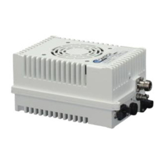
LPOD-R
Outdoor Amplifier / Block Up Converter (BUC)
LPOD-R PS .5
(Running FW-0020841 firmware only – see MN-LPODR Rev. 0 for
LPOD-R PS .5 running FW-0020765 firmware)
LPOD-R PS 1, PS 1.5
(Running FW-0020880 firmware)
Installation and Operation Manual
Part Number MN-LPODR / CD-LPODR
Revision 3
IMPORTANT NOTE: The information contained in this document supersedes all previously published
information regarding this product. Product specifications are subject to change without prior notice.
Part Number MN-LPODR / CD-LPODR Revision 3
Advertisement
Table of Contents

Related Manuals for Comtech EF Data LPOD-R PS .5


Summary of Contents for Comtech EF Data LPOD-R PS .5
- Page 1 LPOD-R Outdoor Amplifier / Block Up Converter (BUC) LPOD-R PS .5 (Running FW-0020841 firmware only – see MN-LPODR Rev. 0 for LPOD-R PS .5 running FW-0020765 firmware) LPOD-R PS 1, PS 1.5 (Running FW-0020880 firmware) Installation and Operation Manual Part Number MN-LPODR / CD-LPODR...
- Page 2 Copyright © 2016 Comtech EF Data. All rights reserved. Printed in the USA. Comtech EF Data, 2114 West 7th Street, Tempe, Arizona 85281 USA, 480.333.2200, FAX: 480.333.2161...
- Page 3 Errata A for MN-LPODR Rev 3 Comtech EF Data Documentation Update Subject: Chapter 1, Section 1.4.4, Power Supply, 2 Bullet Errata Part Number: ER-LPODR-EA3 (Errata documents are not subject to revision.) The new information will be included in the next released revision of the manual.
- Page 4 Blank Page ER-LPODR-EA3 Rev -...
-
Page 5: Table Of Contents
Safety and Compliance ................. xiii Electrical Safety and Compliance ..............xiii Installation Guidelines Regarding Power Line Quality ........xiv Product Support .................... xv Comtech EF Data Headquarters ..............xv Warranty Policy ..................... xv Limitations of Warranty ..................xvi Exclusive Remedies................... xvii CHAPTER 1. - Page 6 1.5.2 Environmental ..................1–9 1.5.3 Physical ....................1–9 Dimensional Envelopes ..............1–10 1.6.1 LPOD-R PS .5 Dimensional Envelopes ..........1–10 1.6.2 LPOD-R PS 1 Dimensional Envelopes ..........1–14 1.6.3 LPOD-R PS 1.5 Dimensional Envelopes ..........1–17 CHAPTER 2. SYSTEM CONNECTORS, INSTALLATION, AND STARTUP ..................
-
Page 7: Table Of Contents
LPOD-R Outdoor Amplifier / Block Up Converter (BUC) MN-LPODR / CD-LPODR Table of Contents Revision 3 2.3.4.3 ‘J3 | POWER IN’ – PS 1.5 Optional DC Power Main ....2–7 2.3.5 ‘J6 | COM1’ Ethernet Communications Port ........2–8 2.3.5.1 Fabricating a Weatherproof Ethernet Cable ...... - Page 8 LPOD-R Outdoor Amplifier / Block Up Converter (BUC) MN-LPODR / CD-LPODR Table of Contents Revision 3 3.2.4.1 Use Windows Desktop to Make a Folder ........3–8 3.2.4.2 Use Windows Explorer to Make a Folder ........3–8 3.2.4.3 Use the Run and Browse Windows to Make a Folder ....3–9 3.2.4.4 Use Windows Command-line or Command Prompt to Make a Folder...
- Page 9 LPOD-R Outdoor Amplifier / Block Up Converter (BUC) MN-LPODR / CD-LPODR Table of Contents Revision 3 4.4.3.3 Page Sections ................4–9 4.4.3.4 Action Buttons ................4–9 4.4.3.5 Drop-down Lists................. 4–9 4.4.3.6 Text or Data Entry ..............4–10 HTTP Interface Page Examples and Descriptions ......4–11 4.5.1 Home Pages..................
-
Page 10: Tables
A.3.1 RF Cable (Type ‘N’) ................A-6 APPENDIX B. MAINTENANCE ............B–1 Overview ..................B–1 Clean the LPOD-R PS .5 Heat Sinks ............. B–2 Clean the LPOD-R PS 1 Heat Sinks ............B–7 Clean the LPOD PS 1.5 Heat Sinks ............ B–10 Water Tight Sealing ................. -
Page 11: Figures
Table of Contents Revision 3 Table 2-3. LPOD-R PS .5 ‘J3 | POWER IN’ Pin Assignments ......... 2–6 Table 2-4. LPOD-R PS 1 ‘J3 | POWER IN’ Pin Assignments ........2–7 Table 2-5. LPOD-R PS 1.5 ‘J3 | POWER IN’ Pin Assignments ....... 2–7 Table 2-6. - Page 12 Figure B-4. Remove the Cover Plate ..............B–4 Figure B-5. Set Aside the Fan Assembly .............. B–5 Figure B-6. LPOD-R PS .5 Heat Sink Locations (Fan Not Shown for Clarity) ..B–5 Figure B-7. Reseat the Fan Assembly ..............B–6 Figure B-8.
-
Page 13: Preface
Guide (CEFD P/N MN-CRFC) Disclaimer Comtech EF Data has reviewed this manual thoroughly in order to provide an easy-to-use guide to this equipment. All statements, technical information, and recommendations in this manual and in any guides or related documents are... -
Page 14: Conventions And References
Further, Comtech EF Data reserves the right to make changes in the specifications of the products described in this manual at any time without notice and without obligation to notify any person of such changes. -
Page 15: Examples Of Multi-Hazard Notices
POWER SUPPLY INPUT. This equipment has been designed to minimize exposure of personnel to hazards. For further information, contact Comtech EF Data Product Support. The operators and technicians must: • Know how to work around, with, and on high voltage equipment. -
Page 16: Installation Guidelines Regarding Power Line Quality
• Be familiar with the warnings presented in this manual. Installation Guidelines Regarding Power Line Quality Comtech EF Data has become familiar with the varying quality of the AC power grid around the world. Observing the following installation guidelines should help ensure a reliable installation. -
Page 17: Product Support
Comtech EF Data for the warranty period specific to the product purchased. For equipment under warranty, the owner is responsible for freight to Comtech EF Data and all related customs, taxes, tariffs, insurance, etc. Comtech EF Data is responsible for the freight charges only for return of the equipment from the factory to the owner. -
Page 18: Limitations Of Warranty
The warranty does not apply to any part of a product that has been installed, altered, repaired, or misused in any way that, in the opinion of Comtech EF Data Corporation, would affect the reliability or detracts from the performance of any... -
Page 19: Exclusive Remedies
The remedies provided herein are the buyer’s sole and exclusive remedies. Comtech EF Data shall not be liable for any direct, indirect, special, incidental, or consequential damages, whether based on contract, tort, or any other legal theory. - Page 20 LPOD-R Outdoor Amplifier / Block Up Converter (BUC) MN-LPODR Preface Revision 3 Notes: xviii...
-
Page 21: Chapter 1. Introduction
These include ship-borne antenna systems, small “flyaway” systems, and Satellite News Gathering (SNG) installations. As shown in Figure 1-1, Comtech EF Data’s LPOD-R is available in three models: the PS .5, the PS 1, and the PS 1.5. Each LPOD-R consists of a CEFD SSPA module... -
Page 22: Features
MN-LPODR Introduction Revision 3 with the Monitor/Control Processor (MCP), a power supply, and a fan assembly. The amplifier features a Comtech EF Data low loss combining technique and MCP-based temperature-versus-gain compensation. 1.3 Features 1.3.1 The Solid-State Advantage The LPOD-R is constructed with highly reliable gallium arsenide field-effect transistors (GaAs FETs). -
Page 23: Data Logging Capability
LPOD-R Outdoor Amplifier / Block Up Converter (BUC) MN-LPODR Introduction Revision 3 1.3.3.2 Data Logging Capability To enhance system maintainability, the LPOD-R includes a built-in data logging capability. By recording critical operational parameters such as temperature, output power, mute status, etc. at time stamped intervals, you can quickly gather intelligence about not only the unit itself but also the unit’s operational environment. -
Page 24: Sspa Module
LPOD-R Outdoor Amplifier / Block Up Converter (BUC) MN-LPODR Introduction Revision 3 Figure 1-2. LPOD-R Typical Block Diagram 1.4.2 SSPA Module The amplifier module performs the core function of the unit. An isolator is at the RF input to ensure good voltage standing wave ratio (VSWR). The RF signal then passes through an electronically controlled attenuator that adjusts the overall attenuation according to the user input. -
Page 25: Cooling System
LPOD-R Outdoor Amplifier / Block Up Converter (BUC) MN-LPODR Introduction Revision 3 1.4.3 Cooling System • The PS .5 contains a single fan that is always enabled. • The PS 1 contains one temperature-controlled fan. • The PS 1.5 contains two temperature-controlled fans. 1.4.4 Power Supply The LPOD-R features a power supply that is power factor corrected. -
Page 26: Monitor And Control (M&C)
The LPOD-R PS .5 features a Light-Emitting Diode (LED) Indicator. Figure 1-3 shows the location of this feature, on the signal output side of the LPOD-R PS .5 housing, next to the ground lug. This LED provides you with visual cues to the operational, online, and offline status of the system. -
Page 27: Summary Of Specifications
LPOD-R Outdoor Amplifier / Block Up Converter (BUC) MN-LPODR Introduction Revision 3 1.5 Summary of Specifications 1.5.1 Characteristics Note 1 IF Input Frequency RF Output Frequency 950 – 1525 MHz 5.850 – 6.425 GHz 950 – 1750 MHz 5.850 – 6.650 GHz (optional) 950 –... - Page 28 LPOD-R Outdoor Amplifier / Block Up Converter (BUC) MN-LPODR Introduction Revision 3 PS .5 60 (65 dB) Gain Min (Typical) PS 1, 1.5 70 (75dB) Input Power Supply 90-264 VAC, 47-63 Hz, Power Factor Corrected, .96 (PS 1, 1.5 Requirements only)(48 VDC optional) Max IF Input level (No Damage) +10 dBm...
-
Page 29: Environmental
LPOD-R Outdoor Amplifier / Block Up Converter (BUC) MN-LPODR Introduction Revision 3 1.5.2 Environmental Standard -40° to 131°F (-40° to 55°C)° Operating -58° to 131°F (-50° to 55°C) or -40° to 140°F (-40° to Temperature Optional 60°C) Storage -67° to 167°F (-55° to 75°C) Humidity 100% condensing rain 2”... -
Page 30: Dimensional Envelopes
Typical for all figures in each subsection, all dimensions are in inches. Bracketed dimensions, where shown, are in metric units (mm). All figures depict a waveguide output unless otherwise noted. 1.6.1 LPOD-R PS .5 Dimensional Envelopes Figure 1-4. LPOD-R PS .5 C-Band 10W Unit 1–10... -
Page 31: Figure 1-5. Lpod-R Ps .5 C-Band 20W Unit
LPOD-R Outdoor Amplifier / Block Up Converter (BUC) MN-LPODR Introduction Revision 3 Figure 1-5. LPOD-R PS .5 C-Band 20W Unit 1–11... -
Page 32: Figure 1-6. Lpod-R Ps .5 Ku-Band 8W Unit
LPOD-R Outdoor Amplifier / Block Up Converter (BUC) MN-LPODR Introduction Revision 3 Figure 1-6. LPOD-R PS .5 Ku-Band 8W Unit 1–12... -
Page 33: Figure 1-7. Lpod-R Ps .5 Ku-Band 16W Unit
LPOD-R Outdoor Amplifier / Block Up Converter (BUC) MN-LPODR Introduction Revision 3 Figure 1-7. LPOD-R PS .5 Ku-Band 16W Unit 1–13... -
Page 34: Lpod-R Ps 1 Dimensional Envelopes
LPOD-R Outdoor Amplifier / Block Up Converter (BUC) MN-LPODR Introduction Revision 3 1.6.2 LPOD-R PS 1 Dimensional Envelopes Figure 1-8. LPOD-R PS 1 C-Band Unit – Coaxial Output 1–14... -
Page 35: Figure 1-9. Lpod-R Ps 1 C-Band Unit
LPOD-R Outdoor Amplifier / Block Up Converter (BUC) MN-LPODR Introduction Revision 3 Figure 1-9. LPOD-R PS 1 C-Band Unit 1–15... -
Page 36: Figure 1-10. Lpod-R Ps 1 Ku-Band Unit
LPOD-R Outdoor Amplifier / Block Up Converter (BUC) MN-LPODR Introduction Revision 3 Figure 1-10. LPOD-R PS 1 Ku-Band Unit 1–16... -
Page 37: Lpod-R Ps 1.5 Dimensional Envelopes
LPOD-R Outdoor Amplifier / Block Up Converter (BUC) MN-LPODR Introduction Revision 3 1.6.3 LPOD-R PS 1.5 Dimensional Envelopes Figure 1-11. LPOD-R PS 1.5 C-Band Unit 1–17... -
Page 38: Figure 1-12. Lpod-R Ps 1.5 Ku-Band Unit
LPOD-R Outdoor Amplifier / Block Up Converter (BUC) MN-LPODR Introduction Revision 3 Figure 1-12. LPOD-R PS 1.5 Ku-Band Unit 1–18... -
Page 39: Startup
Chapter 2. SYSTEM CONNECTORS, A ND INSTALLATION, STARTUP 2.1 Overview • See Chapter 4. ETHERNET INTERFACE OPERATION for information about using the LPOD-R’s remote Ethernet M&C functionality. • See Chapter 5. OPTIONAL SERIAL INTERFACE OPERATION (PS 1, PS 1.5 ONLY) for information about using the LPOD-R’s optional serial-based remote commands and queries. -
Page 40: Water Tight Sealing
Should you receive an accessory kit that contains only the mating cable connectors, or if you (the end-user) choose to supply your own cables and connectors, Comtech EF Data strongly recommends that you use an adhesive lined heatshrink such as TE Connectivity #ATUM-24/6-0 (or equivalent) to cover the connector strain-relief area. -
Page 41: Lpod-R Interface Connectors
Revision 3 2.3 LPOD-R Interface Connectors The LPOD-R external connectors provide all necessary connections between the LPOD-R PS .5 (Figure 2-1), PS 1 (Figure 2-2), or PS 1.5 (Figure 2-3) unit and other equipment. Figure 2-1. LPOD-R PS .5 Connectors Figure 2-2. -
Page 42: J1 | Lband In' Signal Input Port
LPOD-R Outdoor Amplifier / Block Up Converter (BUC) MN-LPODR System Connectors, Installation, and Startup Revision 3 2.3.1 ‘J1 | LBAND IN’ Signal Input Port The ‘J1 | LBAND IN’ RF input connector is a Type ‘N’ female connector. Typical input levels (-30 dBm) depend on desired output power and unit attenuation. -
Page 43: J3 | Power In' Ac Power Main (Ps 1, Ps 1.5 Only)
LPOD-R Outdoor Amplifier / Block Up Converter (BUC) MN-LPODR System Connectors, Installation, and Startup Revision 3 2.3.3 ‘J3 | POWER IN’ AC Power Main (PS 1, PS 1.5 ONLY) WARNING! 1) The LPOD PS .5 is available only as a DC unit. 2) For safety reasons, you must use the correct pin assignments. -
Page 44: J3 | Power In' Standard Or Optional Dc Power Mains
See Sect. 1.5 Summary of Specifications for more information. 2.3.4.1 ‘J3 | POWER IN’ – PS .5 Standard DC Power Main The mating connector specification and the pin assignments specific to the LPOD-R PS .5 standard DC power interface are as follows: Mating Connector: CEFD P/N CN-0020708 (SOURIAU UTS6JC8E33S) Table 2-3. -
Page 45: J3 | Power In' - Ps 1 Optional Dc Power Main
LPOD-R Outdoor Amplifier / Block Up Converter (BUC) MN-LPODR System Connectors, Installation, and Startup Revision 3 2.3.4.2 ‘J3 | POWER IN’ – PS 1 Optional DC Power Main The mating connector specification and the pin assignments specific to the LPOD-R PS 1 optional DC power interface are as follows: Mating Connector: CEFD P/N CN/STPG04F01 (Glenair IPT06E-12-4-SSR-F7) -
Page 46: J6 | Com1' Ethernet Communications Port
LPOD-R Outdoor Amplifier / Block Up Converter (BUC) MN-LPODR System Connectors, Installation, and Startup Revision 3 2.3.5 ‘J6 | COM1’ Ethernet Communications Port See Chapter 4. ETHERNET INTERFACE OPERATION for information about using the LPOD-R’s remote Ethernet M&C functionality. Connector Type Ref Des | Name Direction Weatherproof RJ-45... -
Page 47: Fabricating A Weatherproof Ethernet Cable
Revision 3 2.3.5.1 Fabricating a Weatherproof Ethernet Cable Comtech EF Data offers two mating connector kits: • Use CEFD P/N KT-0020707 for 5.00-5.75 mm jacket OD Ethernet cables. • Use CEFD P/N KT-0020708 for 5.75-6.50 mm jacket OD Ethernet cables. -
Page 48: Figure 2-4. Lpod-R Ethernet Connector Field Termination Kit Assembly
LPOD-R Outdoor Amplifier / Block Up Converter (BUC) MN-LPODR System Connectors, Installation, and Startup Revision 3 Assembly Detail Source: Samtec USA Corporation) CEFD KIT / QTY REQ’D ITEM SAMTEC PART NO. DESCRIPTION KT-0020707 KT-0020708 5.6mm OD 8-wire CAT5e LENGTH A/R –... -
Page 49: J6 | Com1' Remote Communications And Discrete Control Port (Optional)
LPOD-R Outdoor Amplifier / Block Up Converter (BUC) MN-LPODR System Connectors, Installation, and Startup Revision 3 2.3.6 ‘J6 | COM1’ Remote Communications and Discrete Control Port (OPTIONAL) See CHAPTER 5. OPTIONAL SERIAL INTERFACE OPERATION (PS 1, PS 1.5 ONLY) for information about using the optional serial-based remote commands and queries. -
Page 50: About Circular Connectors
LPOD-R Outdoor Amplifier / Block Up Converter (BUC) MN-LPODR System Connectors, Installation, and Startup Revision 3 2.3.6.1 About Circular Connectors Circular connector pairs (Figure 2-5) feature a sleeve lock configuration, with an array of pins (male side) coupled to mating sockets (female side). Feature Description Primary Alignment features... -
Page 51: Ground Connector
LPOD-R Outdoor Amplifier / Block Up Converter (BUC) MN-LPODR System Connectors, Installation, and Startup Revision 3 2.3.7 Ground Connector Use this #10-32 stud, available where shown in Figure 2-6, to connect a common chassis ground among equipment. Figure 2-6. LPOD-R Ground Connector Locations 2–13... -
Page 52: Lpod-R Standalone (Single-Thread) Installations
LPOD-R PS 1 or PS 1.5 Standalone System. 2.4.2 Typical Required Installation Tools Comtech EF Data recommends that, at a minimum, you use these tools to install any LPOD-R Standalone System: • Adjustable wrench; • English and Metric unit box or socket wrenches (hex nuts and hex head bolts are used);... -
Page 53: Pole Mount Installations (Ps 1, Ps 1.5)
LPOD-R Outdoor Amplifier / Block Up Converter (BUC) MN-LPODR System Connectors, Installation, and Startup Revision 3 2.4.3 Pole Mount Installations (PS 1, PS 1.5) The Universal Pole Mount Kit PL/12319-1 is used in combination with pole- mounted standalone installation kits. For purpose of brevity, all subsequent mention of this kit’s usage refers you back to this chapter section. -
Page 54: Pl/12319 Universal Pole Mounting Kit
LPOD-R Outdoor Amplifier / Block Up Converter (BUC) MN-LPODR System Connectors, Installation, and Startup Revision 3 2.4.3.1 PL/12319 Universal Pole Mounting Kit This kit accommodates a pole diameter of up to 13.00” (33.02 cm) OD maximum. ITEM CEFD PART NO. DESCRIPTION DUAL CHANNEL UNISTRUT (SHOWN FOR CLARITY ONLY –... - Page 55 LPOD-R Outdoor Amplifier / Block Up Converter (BUC) MN-LPODR System Connectors, Installation, and Startup Revision 3 Do these steps to install each kit: 1. Place the Unistrut (Item 1, part of the LPOD-R Mounting Kit) on a flat surface. 2. Slide both spring nuts (Item 2) into the Unistrut channel. Make sure to seat the springs against the interior wall of the channel.
-
Page 56: Figure 2-8. Universal Pole Mounting Kit - Final Assembly
LPOD-R Outdoor Amplifier / Block Up Converter (BUC) MN-LPODR System Connectors, Installation, and Startup Revision 3 The assembled kit appears as shown in the top and side view example shown in Figure 2-8. Depending on the application, you may proceed to the next phase of installation. -
Page 57: Kt-0000095 Single Unit Mounting Kit (Ps 1, Ps 1.5)
LPOD-R Outdoor Amplifier / Block Up Converter (BUC) MN-LPODR System Connectors, Installation, and Startup Revision 3 2.4.3.2 KT-0000095 Single Unit Mounting Kit (PS 1, PS 1.5) Use this kit in combination with the PL/12319-1 Universal Pole Mounting Kit. ITEM CEFD PART NO. DESCRIPTION FP-0000534 BRACKET, MOUNTING... -
Page 58: Spar Mount Installation (Ps 1, Ps 1.5)
LPOD-R PS 1 and PS 1.5 standalone configurations, in addition to satellite dish support pole mounted installations, may be installed on the antenna spar. Figure 2-10 shows a typical Comtech EF Data spar mount SSPA installation. The kit that is required for the installation of your LPOD-R system (Figure 2-11) is determined by the spar that is used by the antenna’s manufacturer. -
Page 59: Figure 2-11. Lpod-R Ps 1, Ps 1.5 Spar Mount Installation Kits
LPOD-R Outdoor Amplifier / Block Up Converter (BUC) MN-LPODR System Connectors, Installation, and Startup Revision 3 CEFD KIT / QTY REQ’D DESCRIPTION ITEM CEFD PART NO. [dims in mm] 0000083 0000084 0000085 0000289 BRACKET, MOUNTING, – – – FP-0000547 1.5” x 2.0” [38.1 X 50.8] SPAR BRACKET, MOUNTING, –... -
Page 60: Kt-0020987 Omt-Mount Installation (Ps .5)
LPOD-R Outdoor Amplifier / Block Up Converter (BUC) MN-LPODR System Connectors, Installation, and Startup Revision 3 2.4.5 KT-0020987 OMT-Mount Installation (PS .5) Use this kit to install your LPOD-R PS .5 standalone configuration on the antenna orthomode transducer (OMT). ITEM CEFD PART NO. DESCRIPTION FP-0021719... -
Page 61: Lpod-R Startup
Indicator (PS .5 ONLY) The LPOD-R PS .5 unit features a multi-color Light-Emitting Diode (LED) Indicator. This LED is located on the signal output side of the LPOD-R PS .5 housing, next to the ground lug. See Figure 2-13. Upon power-up of the unit, this LED provides visual cues as to the operational status and LO setting for the system. -
Page 62: Recovering The User Interface Access
LPOD-R Outdoor Amplifier / Block Up Converter (BUC) MN-LPODR System Connectors, Installation, and Startup Revision 3 Table 2-7. LPOD-R PS .5 LED Operation OPERATING STATUS LED COLOR UNIT STATE Green Unmuted, 13.05 GHz LO Standard 14.0-14.5 GHz Yellow Muted, 13.05 GHz LO Uplink Frequency Faulted, 13.05 GHz LO... - Page 63 LPOD-R Outdoor Amplifier / Block Up Converter (BUC) MN-LPODR System Connectors, Installation, and Startup Revision 3 g. In the ‘This connection uses the following items:’ window, select ‘Internet Protocol Version TCP/IPv4’. IMPORTANT: Make sure that you do not uncheck the checkbox.
- Page 64 LPOD-R Outdoor Amplifier / Block Up Converter (BUC) MN-LPODR System Connectors, Installation, and Startup Revision 3 Notes: 2–26...
-
Page 65: Chapter 3. Firmware Update
3.1 Firmware Overview Make sure to operate the LPOD-R with its latest available firmware. Comtech EF Data’s LPOD-R family of Outdoor Amplifiers / Block Up Converters (BUCs) are factory-shipped with the latest version of operating firmware. If you need to update the firmware, you can apply the update to the LPOD-R without having to remove it from operation. -
Page 66: About Firmware Numbers, File Versions, And Formats
3. Extract the firmware update files from the archive download file. You may then use Comtech’s “CReflash” utility. (This utility is only provided in the LPOD-R PS .5 firmware archive download, but it may also be used for the PS1 and PS1.5 firmware update procedures.) Otherwise, you must use the LPOD-R Management IP Address to connect the FTP client to an FTP server, and then FTP-transfer the files from the User PC to the LPOD-R. -
Page 67: Prepare For The Firmware Download
Ethernet ports, a compatible Web browser (e.g., Internet Explorer), and a terminal emulator program (e.g., Tera Term or HyperTerminal). 3.2.1.1 LPOD-R Connections for All Current Production Units Figure 3-1. M&C Utilities Available from Comtech EF Data (All Current LPOD-R Models) See Figure 3-1: You can use Comtech’s optional LPODnet (part of CEFD KT-0000203 M&C... -
Page 68: Lpod-R Connections For Earlier Ps 1 Or Ps 1.5 Units
LPOD-R PS1 or PS 1.5 Models) See Figure 3-2: • You can use Comtech EF Data’s optional CLC-10 Handheld Terminal (part of CEFD M&C Accessory Kit KT-0020518) for serial-based monitor and control of the LPOD-R PS 1 or PS 1.5 (when the optional EIA-232/485 serial interface is available). -
Page 69: Configure The Terminal Emulator Program
LPOD-R Outdoor Amplifier / Block Up Converter (BUC) MN-LPODR Firmware Update Revision 3 • Use the 19 pin-to-RJ-45 adapter cable (CEFD P/N CA-0000352) that is part of the KT-0000203 LPODnet Netbook Accessory Kit to connect the LPODnet or the User PC to the LPOD-R PS 1 or PS 1.5 19-pin ‘J6 | COM1’ port. -
Page 70: Use The Http Interface To Find The Firmware Information
• The ‘Summary’ section of the ‘Status | Summary’ page provides the firmware details as “FW Revision”, “Active Software Image”, and “Next Reboot Image”, as shown in this example: 2. Write down your firmware information for further reference or to provide to Comtech EF Data Product support. 3–6... -
Page 71: Use The Optional Serial Interface To Find The Firmware Information
LPOD-R Outdoor Amplifier / Block Up Converter (BUC) MN-LPODR Firmware Update Revision 3 3.2.3.2 Use the Optional Serial Interface to Find the Firmware Information Chapter 5. OPTIONAL SERIAL INTERFACE OPERATION (PS 1, PS 1.5 ONLY) Use your terminal emulator program or CLC-10 to execute remote queries with the LPOD-R. -
Page 72: Use Windows Desktop To Make A Folder
LPOD-R Outdoor Amplifier / Block Up Converter (BUC) MN-LPODR Firmware Update Revision 3 3.2.4.1 Use Windows Desktop to Make a Folder Do these steps: 1. Right-click anywhere on the desktop to open the popup submenu. 2. Select New > Folder to make the new, temporary folder on the desktop. 3. -
Page 73: Use The Run And Browse Windows To Make A Folder
LPOD-R Outdoor Amplifier / Block Up Converter (BUC) MN-LPODR Firmware Update Revision 3 3.2.4.3 Use the Run and Browse Windows to Make a Folder Select Start on the Windows taskbar and then do these steps: 1. Click Run… to open the Run window. 2. -
Page 74: Download And Extract The Firmware Update Files
LPOD-R Outdoor Amplifier / Block Up Converter (BUC) MN-LPODR Firmware Update Revision 3 3. From the c:\> prompt, type either “mkdir temp” or “md temp” (both “mkdir” and “md” mean “make directory”), and then press Enter. There will now be a “temp” folder created and available for placement of the firmware file download. - Page 75 LPOD-R Outdoor Amplifier / Block Up Converter (BUC) MN-LPODR Firmware Update Revision 3 o Click [Run] to open the self-extractor dialogue window. Use [Browse] to select your destination folder. Click [Unzip] to extract the files. Your results display as per this example – click[OK] to close.
-
Page 76: Use Windows Desktop To View Folder Contents
8. If not already done with File Download > Open, you must extract, at a minimum, these files (filenames are subject to change): • FOR THE LPOD-R PS .5: o FW-0020841X_###.bin – The Firmware Bulk image file o ReleaseNotes_ FW-0020841x_v#_#_#.pdf – The Firmware Release Notes PDF file o CReflash.exe –The Firmware Update Utility program... -
Page 77: Use Windows Command-Line To View Folder Contents
LPOD-R Outdoor Amplifier / Block Up Converter (BUC) MN-LPODR Firmware Update Revision 3 3.3.1.2 Use Windows Command-line to View Folder Contents Using Command-line or Command Prompt: 1. Type “cd c:\temp” at the Windows Command-line prompt to change to the temporary folder (directory) created earlier using Command-line. 2. -
Page 78: Steps To Ftp Upload The Firmware Files
LPOD-R Outdoor Amplifier / Block Up Converter (BUC) MN-LPODR Firmware Update Revision 3 2. Enter your upload parameters information into CReflash: a. Left-click in the “IP Address:” text box, and enter the default Management IP Address (e.g., 192.168.1.4). b. Left-click in the “Local Filename:” text box. Then, click [Browse] and navigate to the temporary folder created earlier. -
Page 79: Steps To Update The Lpod-R Unit
Type “prompt”. d. Type “hash”. e. To begin the file transfer: • For the LPOD-R PS .5 only, type “put FW-0020841X.bin a:\bulk.bin:” • For the LPOD-R PS 1 or 1.5, type “put FW-0020880X.bin a:\bulk.bin:” The destination “a:\bulk.bin:” must be all lower-case. - Page 80 LPOD-R Outdoor Amplifier / Block Up Converter (BUC) MN-LPODR Firmware Update Revision 3 4. After the unit has rebooted with the new firmware, if the optional serial interface is available you may clear the trending data. Use the terminal emulator or CLC-10 Handheld Terminal to enter serial remote command <0/CTD=1[cr].
-
Page 81: Chapter 4. Ethernet Interface Operation
Network Monitoring System (NMS) and a user-supplied Management Information Base (MIB) File Browser. CAUTION Comtech EF Data recommends use of the Ethernet-based SNMP interface for advanced users only. All other users are strongly encouraged to use the LPOD-R HTTP Interface for remote Monitor and Control (M&C) of the LPOD-R. -
Page 82: Snmp Interface
LPOD-R Outdoor Amplifier / Block Up Converter MN-LPODR Ethernet Interface Operation Revision 3 • The LPOD-R is operating with the latest version firmware files. • The User PC is running a terminal emulation program for operation of the LPOD-R Telnet Interface. •... -
Page 83: Comtechefdata Root Mib File
Ethernet Interface Operation Revision 3 4.2.1.1 ComtechEFData Root MIB file • FW-0000291x.mib • ComtechEFData MIB file gives the root tree for all Comtech EF Data LPOD-R products (PSx) and consists of only the following OID: o Name: comtechEFData o Type: MODULE-IDENTITY o OID: 1.3.6.1.4.1.6247... -
Page 84: Telnet Interface
LPOD-R Outdoor Amplifier / Block Up Converter MN-LPODR Ethernet Interface Operation Revision 3 For correct SNMP operation, the LPOD-R MIB files must be used with the associated version of the LPOD-R M&C. See the LPOD-R FW Release Notes for information on the required FW/SW compatibility. 4.3 Telnet Interface Chapter 5. -
Page 85: Configure Hyperterminal For Telnet Remote Control Operation
LPOD-R Outdoor Amplifier / Block Up Converter MN-LPODR Ethernet Interface Operation Revision 3 To see the full response messages, you can use the HyperTerminal terminal emulation program configured as a Telnet client. An example of the login process and remote control operation, when using HyperTerminal as the interface, is shown here: Figure 4-2. -
Page 86: Http (Web Server) Interface
LPOD-R Outdoor Amplifier / Block Up Converter MN-LPODR Ethernet Interface Operation Revision 3 1. Make sure to define the Connect To Telnet connection properties correctly (File Properties)(Figure 4-3, left): a. Enter the LPOD-R’s Traffic/Management IP Address as the “Host address”... -
Page 87: Http Interface User Login
LPOD-R Outdoor Amplifier / Block Up Converter MN-LPODR Ethernet Interface Operation Revision 3 5. Use the command IPA=xxx.xxx.xxx.xxx.yy, where “xxx.xxx.xxx.xxx” is a valid IP Address on the network where the unit is to be installed, and “yy” is the subnet range (typically, yy = 24). 1) You must assign a unique IP Address for each unit on the network before connecting to an existing network. -
Page 88: Http Interface Features
LPOD-R Outdoor Amplifier / Block Up Converter MN-LPODR Ethernet Interface Operation Revision 3 Once the valid User Name and Password is accepted, the LPOD-R HTTP Interface splash page shows (Figure 4-4). The unit and firmware version in this example will differ from your setup. Figure 4-4. -
Page 89: Page Navigation
LPOD-R Outdoor Amplifier / Block Up Converter MN-LPODR Ethernet Interface Operation Revision 3 4.4.3.2 Page Navigation The HTTP Interface has four navigation tabs at the top of each page. Click a navigation tab to see its page hyperlinks. Click a page hyperlink to open a page. This manual uses a convention for all web pages to show you how to navigate to the featured page: Navigation Tab | Page Hyperlink. -
Page 90: Text Or Data Entry
LPOD-R Outdoor Amplifier / Block Up Converter MN-LPODR Ethernet Interface Operation Revision 3 4.4.3.6 Text or Data Entry Text boxes let you type data into a field. An action button can be associated with a single text box, or a group of text boxes. -
Page 91: Http Interface Page Examples And Descriptions
LPOD-R Outdoor Amplifier / Block Up Converter MN-LPODR Ethernet Interface Operation Revision 3 4.5 HTTP Interface Page Examples and Descriptions 4.5.1 Home Pages 4.5.1.1 Home | Home Use this page to identify the product. Click the Home navigation tab or the page hyperlink to return to this page from anywhere in the HTTP Interface. -
Page 92: Admin
LPOD-R Outdoor Amplifier / Block Up Converter MN-LPODR Ethernet Interface Operation Revision 3 4.5.2 Admin Pages The Admin pages are available only to users who have logged in using the Administrator Name and Password. Use these administrator pages to set up user access. Click Access or SNMP to continue. - Page 93 LPOD-R Outdoor Amplifier / Block Up Converter MN-LPODR Ethernet Interface Operation Revision 3 System Account Access Information Name fields can be any alphanumeric combination with a maximum length of 10 characters. Password fields can be any alphanumeric combination with a maximum length of 10 characters.
-
Page 94: Admin | Snmp
LPOD-R Outdoor Amplifier / Block Up Converter MN-LPODR Ethernet Interface Operation Revision 3 4.5.2.2 Admin | SNMP The Administrator must use this page to manage LPOD-R SNMP (Simple Network Management Protocol) settings. Refresh the page to see the latest data. Figure 4-8. -
Page 95: Config
LPOD-R Outdoor Amplifier / Block Up Converter MN-LPODR Ethernet Interface Operation Revision 3 4.5.3 Config Pages Use the Configuration pages to configure all operating parameters for the LPOD-R. Click Amplifier or Utility to continue, 4.5.3.1 Config | Amplifier Use this page to configure the communications, operations and alarms/faults handling for the amplifier. -
Page 96: Config | Utility
LPOD-R Outdoor Amplifier / Block Up Converter MN-LPODR Ethernet Interface Operation Revision 3 FSK Address Set the FSK (Frequency Shift Keying) Address from 01 to 15. Click Change to save any changes. 4.5.3.2 Config | Utility Use this page to configure additional LPOD-R operating parameters. Refresh the page to see the latest data. - Page 97 LPOD-R Outdoor Amplifier / Block Up Converter MN-LPODR Ethernet Interface Operation Revision 3 Circuit ID Enter a Circuit ID string of up to 48 characters. This is the identification label for the unit. Click Change CID to save the change. Current Active Firmware Image # (read-only) The selected Current Active Firmware Image is shown here.
-
Page 98: Status
LPOD-R Outdoor Amplifier / Block Up Converter MN-LPODR Ethernet Interface Operation Revision 3 4.5.4 Status Pages Use these pages to see the unit’s operational status, logged alarm and statistics windows. Click Summary, Status, MOP, Events, Statistics, or Trending Graphs to continue. -
Page 99: Status | Status
LPOD-R Outdoor Amplifier / Block Up Converter MN-LPODR Ethernet Interface Operation Revision 3 To reset the Terminal Status Change from YES to NO, click Clear. 4.5.4.2 Status | Status Use this read-only page see general status data for the LPOD-R. Unlike the pages that you must refresh manually, the Status | Status page updates automatically once every 10 seconds. -
Page 100: Status | Events
LPOD-R Outdoor Amplifier / Block Up Converter MN-LPODR Ethernet Interface Operation Revision 3 4.5.4.4 Status | Events Use this page to see stored events data. Additionally, use it to set the parameters for how the LPOD-R triggers events and alarms. Refresh the page to see the latest data. -
Page 101: Status | Statistics
LPOD-R Outdoor Amplifier / Block Up Converter MN-LPODR Ethernet Interface Operation Revision 3 Alarm Mask Use the drop-down list to select the Low Forward RF Power alarm as Fault, Alarm, or Masked. Click Change Alarm Mask to save these settings. 4.5.4.5 Status | Statistics This page shows all unread, stored statistics. - Page 102 LPOD-R Outdoor Amplifier / Block Up Converter MN-LPODR Ethernet Interface Operation Revision 3 • Select Initialize Statistics Pointer to reset the internal pointer to allow queries to start at the beginning of the statistics log. Click Submit to update the window according to your selection. Statistics Configuration •...
- Page 103 LPOD-R Outdoor Amplifier / Block Up Converter MN-LPODR Ethernet Interface Operation Revision 3 4.5.4.6 Status | Trending Graphs Figure 4-16. Status | Trending Graphs Page Example 4–23...
- Page 104 LPOD-R Outdoor Amplifier / Block Up Converter MN-LPODR Ethernet Interface Operation Revision 3 This scrolling page provides graphs that show trends over time for the following operating parameters: • Amplifier Temperature • Amplifier Output Power • Line Voltage • Line Current (Amp) •...
-
Page 105: Only)
Optional serial-based remote management of Comtech EF Data’s LPOD-R PS 1 and PS 1.5 Outdoor Amplifiers / Block Up Converters (SSPAs/BUCs) is available using the ‘J6 | COM1’ port. Original production units featured a 19-pin circular connector; current production units feature a weatherproof RJ-45 Ethernet port. -
Page 106: Key Operational Parameters / Common Commands And Queries
LPOD-R Outdoor Amplifier / Block Up Converter (BUC) MN-LPODR Optional Serial Interface Operation (PS 1, PS 1.5 ONLY) Revision 3 5.2 Key Operational Parameters / Common Commands and Queries 5.2.1 RF Input Level The required RF input level to reach the full rated output power of the SSPA is determined by the individual amplifier temperature compensated gain and specified power rating. -
Page 107: Power Detector
(Web Server) Interface that can be accessed using a web browser. The SSPA/BUC also supports a Comtech EF Data FSK link that allows one of Comtech EF Data’s modem products to control the SSPA/BUC remotely through the L-Band RF cable. -
Page 108: Packet Structure
LPOD-R Outdoor Amplifier / Block Up Converter (BUC) MN-LPODR Optional Serial Interface Operation (PS 1, PS 1.5 ONLY) Revision 3 All messages from controller to target require a response (with one exception). This will be either to return data that has been requested by the controller, or to acknowledge reception of an instruction to change the configuration of the target. -
Page 109: Address Delimiter
LPOD-R Outdoor Amplifier / Block Up Converter (BUC) MN-LPODR Optional Serial Interface Operation (PS 1, PS 1.5 ONLY) Revision 3 5.3.2.3 Address Delimiter This is the forward slash character: / (ASCII code 47) 5.3.2.4 Instruction Code This three-character alphabetic sequence is intended to be a mnemonic of its operational function. This aids in the readability of the message, should you display it in its raw ASCII form. - Page 110 LPOD-R Outdoor Amplifier / Block Up Converter (BUC) MN-LPODR Optional Serial Interface Operation (PS 1, PS 1.5 ONLY) Revision 3 1. If the Controller sends a command to set a parameter’s value, and the value is valid, the Target accepts the command by replying with no message arguments.
-
Page 111: Optional Message Arguments
LPOD-R Outdoor Amplifier / Block Up Converter (BUC) MN-LPODR Optional Serial Interface Operation (PS 1, PS 1.5 ONLY) Revision 3 5.3.2.8 Optional Message Arguments Arguments are not required for all messages. Arguments include these ASCII codes: • Characters “0” through “9” (ASCII codes 48 through 57) •... -
Page 112: Remote Commands And Queries
Certain commands and queries are marked as End-of-Life (EOL). These features (noted with * in the Parameter Type field) are fully supported in this product; however, Comtech EF Data strongly recommends that you use the equivalent new command or query for new implementations. - Page 113 LPOD-R Outdoor Amplifier / Block Up Converter (BUC) MN-LPODR Optional Serial Interface Operation (PS 1, PS 1.5 ONLY) Revision 3 Controller-to-Target Target-to-Controller Instruction Code and Arguments for (see Description of Arguments) Parameter Type Qualifier Command or Description of Arguments (* indicates Response to (Note that all arguments are ASCII numeric codes from 48 to 57) End-of-Life)
- Page 114 LPOD-R Outdoor Amplifier / Block Up Converter (BUC) MN-LPODR Optional Serial Interface Operation (PS 1, PS 1.5 ONLY) Revision 3 Controller-to-Target Target-to-Controller Instruction Code and Arguments for (see Description of Arguments) Parameter Type Qualifier Command or Description of Arguments (* indicates Response to (Note that all arguments are ASCII numeric codes from 48 to 57) End-of-Life)
- Page 115 LPOD-R Outdoor Amplifier / Block Up Converter (BUC) MN-LPODR Optional Serial Interface Operation (PS 1, PS 1.5 ONLY) Revision 3 Controller-to-Target Target-to-Controller Instruction Code and Arguments for (see Description of Arguments) Parameter Type Qualifier Command or Description of Arguments (* indicates Response to (Note that all arguments are ASCII numeric codes from 48 to 57) End-of-Life)
- Page 116 LPOD-R Outdoor Amplifier / Block Up Converter (BUC) MN-LPODR Optional Serial Interface Operation (PS 1, PS 1.5 ONLY) Revision 3 Controller-to-Target Target-to-Controller Instruction Code and Arguments for (see Description of Arguments) Parameter Type Qualifier Command or Description of Arguments (* indicates Response to (Note that all arguments are ASCII numeric codes from 48 to 57) End-of-Life)
- Page 117 LPOD-R Outdoor Amplifier / Block Up Converter (BUC) MN-LPODR Optional Serial Interface Operation (PS 1, PS 1.5 ONLY) Revision 3 Controller-to-Target Target-to-Controller Instruction Code and Arguments for (see Description of Arguments) Parameter Type Qualifier Command or Description of Arguments (* indicates Response to (Note that all arguments are ASCII numeric codes from 48 to 57) End-of-Life)
- Page 118 LPOD-R Outdoor Amplifier / Block Up Converter (BUC) MN-LPODR Optional Serial Interface Operation (PS 1, PS 1.5 ONLY) Revision 3 Controller-to-Target Target-to-Controller Instruction Code and Arguments for (see Description of Arguments) Parameter Type Qualifier Command or Description of Arguments (* indicates Response to (Note that all arguments are ASCII numeric codes from 48 to 57) End-of-Life)
- Page 119 LPOD-R Outdoor Amplifier / Block Up Converter (BUC) MN-LPODR Optional Serial Interface Operation (PS 1, PS 1.5 ONLY) Revision 3 Controller-to-Target Target-to-Controller Instruction Code and Arguments for (see Description of Arguments) Parameter Type Qualifier Command or Description of Arguments (* indicates Response to (Note that all arguments are ASCII numeric codes from 48 to 57) End-of-Life)
- Page 120 LPOD-R Outdoor Amplifier / Block Up Converter (BUC) MN-LPODR Optional Serial Interface Operation (PS 1, PS 1.5 ONLY) Revision 3 Controller-to-Target Target-to-Controller Instruction Code and Arguments for (see Description of Arguments) Parameter Type Qualifier Command or Description of Arguments (* indicates Response to (Note that all arguments are ASCII numeric codes from 48 to 57) End-of-Life)
- Page 121 LPOD-R Outdoor Amplifier / Block Up Converter (BUC) MN-LPODR Optional Serial Interface Operation (PS 1, PS 1.5 ONLY) Revision 3 Controller-to-Target Target-to-Controller Instruction Code and Arguments for (see Description of Arguments) Parameter Type Qualifier Command or Description of Arguments (* indicates Response to (Note that all arguments are ASCII numeric codes from 48 to 57) End-of-Life)
- Page 122 LPOD-R Outdoor Amplifier / Block Up Converter (BUC) MN-LPODR Optional Serial Interface Operation (PS 1, PS 1.5 ONLY) Revision 3 Controller-to-Target Target-to-Controller Instruction Code and Arguments for (see Description of Arguments) Parameter Type Qualifier Command or Description of Arguments (* indicates Response to (Note that all arguments are ASCII numeric codes from 48 to 57) End-of-Life)
- Page 123 LPOD-R Outdoor Amplifier / Block Up Converter (BUC) MN-LPODR Optional Serial Interface Operation (PS 1, PS 1.5 ONLY) Revision 3 Controller-to-Target Target-to-Controller Instruction Code and Arguments for (see Description of Arguments) Parameter Type Qualifier Command or Description of Arguments (* indicates Response to (Note that all arguments are ASCII numeric codes from 48 to 57) End-of-Life)
- Page 124 LPOD-R Outdoor Amplifier / Block Up Converter (BUC) MN-LPODR Optional Serial Interface Operation (PS 1, PS 1.5 ONLY) Revision 3 Controller-to-Target Target-to-Controller Instruction Code and Arguments for (see Description of Arguments) Parameter Type Qualifier Command or Description of Arguments (* indicates Response to (Note that all arguments are ASCII numeric codes from 48 to 57) End-of-Life)
- Page 125 LPOD-R Outdoor Amplifier / Block Up Converter (BUC) MN-LPODR Optional Serial Interface Operation (PS 1, PS 1.5 ONLY) Revision 3 Controller-to-Target Target-to-Controller Instruction Code and Arguments for (see Description of Arguments) Parameter Type Qualifier Command or Description of Arguments (* indicates Response to (Note that all arguments are ASCII numeric codes from 48 to 57) End-of-Life)
- Page 126 LPOD-R Outdoor Amplifier / Block Up Converter (BUC) MN-LPODR Optional Serial Interface Operation (PS 1, PS 1.5 ONLY) Revision 3 Controller-to-Target Target-to-Controller Instruction Code and Arguments for (see Description of Arguments) Parameter Type Qualifier Command or Description of Arguments (* indicates Response to (Note that all arguments are ASCII numeric codes from 48 to 57) End-of-Life)
- Page 127 LPOD-R Outdoor Amplifier / Block Up Converter (BUC) MN-LPODR Optional Serial Interface Operation (PS 1, PS 1.5 ONLY) Revision 3 Controller-to-Target Target-to-Controller Instruction Code and Arguments for (see Description of Arguments) Parameter Type Qualifier Command or Description of Arguments (* indicates Response to (Note that all arguments are ASCII numeric codes from 48 to 57) End-of-Life)
- Page 128 LPOD-R Outdoor Amplifier / Block Up Converter (BUC) MN-LPODR Optional Serial Interface Operation (PS 1, PS 1.5 ONLY) Revision 3 Controller-to-Target Target-to-Controller Instruction Code and Arguments for (see Description of Arguments) Parameter Type Qualifier Command or Description of Arguments (* indicates Response to (Note that all arguments are ASCII numeric codes from 48 to 57) End-of-Life)
- Page 129 LPOD-R Outdoor Amplifier / Block Up Converter (BUC) MN-LPODR Optional Serial Interface Operation (PS 1, PS 1.5 ONLY) Revision 3 Controller-to-Target Target-to-Controller Instruction Code and Arguments for (see Description of Arguments) Parameter Type Qualifier Command or Description of Arguments (* indicates Response to (Note that all arguments are ASCII numeric codes from 48 to 57) End-of-Life)
- Page 130 LPOD-R Outdoor Amplifier / Block Up Converter (BUC) MN-LPODR Optional Serial Interface Operation (PS 1, PS 1.5 ONLY) Revision 3 Notes: 5–26...
-
Page 131: Appendix A. Cable Drawings
(19-pin circular connector to <2X> RJ-45) (Cable and LPODnet are furnished as part of optional CEFD KIT KT-0000203) Connecting a standalone LPOD-R PS .5, PS 1, or PS 1.5 current production version RJ-45 ‘J6 CAT5e Ethernet Cable | COM1’ weatherproof receptacle to an LPODnet or a user PC Ethernet jack. -
Page 132: Serial Interface Cable - Ps 1 Or Ps 1.5 (Optional
M&C of the LPOD-R. (This is now an optional configuration. This interface is now a weatherproof RJ-45 Ethernet receptacle providing Ethernet-based M&C.) The optional Comtech EF Data CLC-10 Serial M&C Accessory Kit (CEFD P/N KT- 0020518) includes the CA-0020526 Serial Interface Cable. This kit is available to provide optional serial-based M&C of standalone LPOD- R PS 1 and PS 1.5 units using the CLC-10 Comtech LPOD Controller (a preconfigured Two Technologies, Inc. -
Page 133: Ethernet Interface Cable - Ps 1 Or Ps 1.5 (Optional
M&C of the LPOD-R. (This is now an optional configuration. This interface is now a weatherproof RJ-45 Ethernet receptacle providing Ethernet-based M&C.) The optional Comtech EF Data Ethernet Utility Kit (CEFD P/N KT-0000203) includes the LPODnet (a Samsung NB30 Plus Netbook) and the CA-0000352 Ethernet Interface Cable. -
Page 134: Ethernet Data Cable (Cat5E
For permanent Ethernet data connections, you MUST use the appropriate mating connector on your supplied Ethernet cable to ensure a weatherproof installation. Comtech EF Data provides kits for fabricating Ethernet cables having weatherproof connectors. See Section 2.2.5.1 and Figure 2-4 in Chapter 2. SYSTEM CONNECTORS, INSTALLATION, STARTUP for details. -
Page 135: Rf Cables
LPOD-R Outdoor Amplifier / Block Up Converter (BUC) MN-LPODR Appendix A Revision 3 A.3 RF Cables CEFD Figure DESCRIPTION USED FOR: CABLE P/N Type ‘N’ to Type ‘N’ 1/4" Heliax Coaxial Cable CA/3722-X LPOD-R Rx or Tx connections in standalone LPOD-R applications (lengths vary) -
Page 136: Rf Cable (Type 'N
LPOD-R Outdoor Amplifier / Block Up Converter (BUC) MN-LPODR Appendix A Revision 3 A.3.1 RF Cable (Type ‘N’) Use this Type ‘N’ cable for the Tx or Rx connections in LPOD-R standalone or future 1:1 Redundancy applications: • For all LPOD-R standalone applications – This cable connects directly from the Tx signal source to the ‘J1 | L-BAND IN’ LPOD interface. -
Page 137: Appendix B. Maintenance
Appendix B. MAINTENANCE B.1 Overview This appendix outlines the procedures for uninstalling the LPOD-R PS .5, PS 1, or PS 1.5 fan shroud, inspecting and cleaning the heat sinks, and then re-installing the fan shroud. Figure B-1. Comtech EF Data LPOD-R Outdoor Amplifiers / BUCs The fans used by Comtech EF Data’s LPOD-R family of Outdoor Amplifiers / Block... -
Page 138: Clean The Lpod-R Ps .5 Heat Sinks
Figure B-2. LPOD-R HTTP Interface ‘Status | Trending Graphs’ Page – Temperature Graph Example B.2 Clean the LPOD-R PS .5 Heat Sinks Do these steps to clean the LPOD-R PS .5 Heat Sinks: Step Task Disconnect power from the LPOD-R. - Page 139 Then, re-install the four cover screws as described in Step 2. Torque the screws to 11 ±2 inch lbs. Reconnect the power source to the LPOD-R. Figure B-3. LPOD-R PS .5 Cover Plate Screw Locations B–3...
- Page 140 LPOD-R Outdoor Amplifier / Block Up Converter (BUC) MN-LPODR Appendix B Revision 3 Figure B-4. Remove the Cover Plate B–4...
- Page 141 LPOD-R Outdoor Amplifier / Block Up Converter (BUC) MN-LPODR Appendix B Revision 3 Figure B-5. Set Aside the Fan Assembly Figure B-6. LPOD-R PS .5 Heat Sink Locations (Fan Not Shown for Clarity) B–5...
- Page 142 LPOD-R Outdoor Amplifier / Block Up Converter (BUC) MN-LPODR Appendix B Revision 3 Figure B-7. Reseat the Fan Assembly Figure B-8. Replace the Cover Plate B–6...
-
Page 143: Clean The Lpod-R Ps 1 Heat Sinks
LPOD-R Outdoor Amplifier / Block Up Converter (BUC) MN-LPODR Appendix B Revision 3 B.3 Clean the LPOD-R PS 1 Heat Sinks Do these steps to clean the LPOD-R PS 1 Heat Sinks: Step Task Disconnect power from the LPOD-R. Remove the eight screws – four on either side of the fan shroud – see Figure B-9. - Page 144 LPOD-R Outdoor Amplifier / Block Up Converter (BUC) MN-LPODR Appendix B Revision 3 Figure B-9. LPOD-R PS 1 Shroud Screw Locations Figure B-10. Remove the Fan Shroud B–8...
- Page 145 LPOD-R Outdoor Amplifier / Block Up Converter (BUC) MN-LPODR Appendix B Revision 3 Figure B-11. Disconnect the Fan Power Supply Figure B-12. LPOD-R PS 1 Heat Sink Locations Figure B-13. Reconnect the Fan Power Supply B–9...
-
Page 146: Clean The Lpod Ps 1.5 Heat Sinks
LPOD-R Outdoor Amplifier / Block Up Converter (BUC) MN-LPODR Appendix B Revision 3 B.4 Clean the LPOD PS 1.5 Heat Sinks Do these steps to clean the LPOD-R PS 1.5 Heat Sinks: Step Task Disconnect power from the LPOD-R. Remove the screws from all four sides of the LPOD-R as needed – see Figure B-14. - Page 147 LPOD-R Outdoor Amplifier / Block Up Converter (BUC) MN-LPODR Appendix B Revision 3 Step Task Re-install the fan shroud onto the chassis – Make sure to keep the fan power supply cables clear of the fan and heat sink surfaces. Then, re- install all screws as described in Step 2, making sure to re-install the four longer screws at their same locations.
- Page 148 LPOD-R Outdoor Amplifier / Block Up Converter (BUC) MN-LPODR Appendix B Revision 3 Figure B-15. Remove the Fan Shroud Figure B-16. Disconnect the Fan 1 / Fan 2 Power Supplies B–12...
- Page 149 LPOD-R Outdoor Amplifier / Block Up Converter (BUC) MN-LPODR Appendix B Revision 3 Figure B-17. LPOD-R PS 1.5 Heat Sink Location Figure B-18. Reconnect the Fan 1 / Fan 2 Power Supplies B–13...
-
Page 150: Water Tight Sealing
LPOD-R Outdoor Amplifier / Block Up Converter (BUC) MN-LPODR Appendix B Revision 3 B.5 Water Tight Sealing CAUTION Before you resume operation of your equipment, you MUST make sure that all external cable assemblies for the outdoor equipment are properly sealed to prevent water intrusion. Failure to achieve water tight sealing will result in possible performance degradation and even product failure. - Page 152 2114 85281 WEST TH STREET TEMPE ARIZONA 480 • 333 • 2200 PHONE 480 • 333 • 2161...
Need help?
Do you have a question about the LPOD-R PS .5 and is the answer not in the manual?
Questions and answers